


Spectra® Classic
Installation and Operations Manual

SPECTRA®
CLASSIC
installation & operations manual
table of contents
section 0 page 1
section 1
section 2
section 3
INTRODUCTION - ABOUT SPECTRA CLASSIC
1.1 preparation
1.2 wiring
1.3 hooking up the transformer
1.4 sound meter
TROUBLESHOOTING
2.1 common questions
SCHEMATICS
1 POWER ZONE, NO CVC OR TIMER, NO PAGE|MUSIC
1 POWER ZONE, 1 CVC, NO PAGE|MUSIC (AND RCVC OPTION)
1 POWER ZONE, NO CVC OR TIMER, 1 ZONE PAGE|MUSIC
1 POWER ZONE, 1 CVC, 1 ZONE PAGE|MUSIC
2 POWER ZONES, NO CVC OR TIMER, NO PAGE|MUSIC
2 POWER ZONES, 1 CVC,ALL ZONE PAGE/MUSIC
2 POWER ZONES, NO CVC OR TIMER, ALL ZONE PAGE|MUSIC
2 POWER ZONES, 1 CVC, NO PAGE/MUSIC
2 POWER ZONES, 2 CVC’s, NO PAGE/MUSIC
2 POWER ZONES, 1 CVC,NO PAGE/MUSIC
page 2
page 3
p
page 5
pages 6-11
pages 13-24
FIGURE A
FIGURE B
FIGURE C
FIGURE D
FIGURE E
FIGURE F
FIGURE G
FIGURE H
FIGURE I
FIGURE J
age 4
2 POWER ZONES, NO CVC OR TIMER, 2 ZONE PAGE|MUSIC
1 POWER ZONE, 1 TIMER, NO PAGE|MUSIC
1 POWER ZONE, 1 TIMER, 1 ZONE PAGE|MUSIC
2 POWER ZONES, 1 TIMER TO ALL ZONES, ALL ZONE PAGE|MUSIC
2 POWER ZONES, 2 ZONE TIMER, NO PAGE|MUSIC
2 POWER ZONES, 2 ZONE TIMER, ALL ZONE PAGE|MUSIC
FIGURE K
FIGURE L
FIGURE M
FIGURE N
FIGURE O
FIGURE P

Lencore
1
Leave enough cable at each ceiling opening so that you have an extra 3-5 ft. This
cable will be made into a loop once the unit has been hung and put in the ceiling
using a 7” wire tie. The cabling connecting the units should not be too tight. Once
installed, cable cannot touch the ceiling (use the wire ties to accomplish this).
On each main (master) unit, turn each center volume control on the main
(masters) seven clicks & the blue gain control 3/4 clockwise. This is especially
helpful when using a CVC unit. In that case, if the volume is slightly up or down,
all of the units can be adjusted by the CVC. This saves a great deal of time. This
may vary depending on the quantity of units and the height of the plenum area.
Masking units come from the factory pre-set for mineral fiber ceiling tile. If glass
fiber ceiling tile is used, the contour switch must be turned 3/4 to the left towards
the pink spectrum
spectra
All Wire must be UL Usted, Plenum Rated, 18 gauge, stranded, non-shielded
NOTE
If private ofces are included, units should be set
lower in these ofces. Suggest 3 clicks on
center switch and 1/2 turn on gain control.

section 1
2
1.1 | preparation
PRESETTING CVC CENTRAL VOLUME CONTROL OR RCVC
Turn each main (master) center volume control to the 7th position.
Turn the blue gain control 3/4 clockwise. Put the CVC blue central volume control in
the middle position. This is a good starting point. Then only minor volume adjustments
should be made. This setup will vary from location to location and will also vary
depending on plenum heights.
HANG SOUND MASKING UNITS
Use Erica Multi-Function Clips, 4-Z-3-4 to hang units. Hang them approximately 10”
above the ceiling tile at the designated location. Each Spectra® unit is suspended from
the nearest T -Bar hanger by chain. It is important you hang the units at a uni form height
throughout, otherwise, you risk the chance of less uniformity of sound when the units
are turned on.
FIND OUT IF PLENUM RATED TIE WRAPS MUST BE USED ON YOUR
PARTICULAR PROJECT
The units are normally placed 6-9ft. from the hard walls and usually 12-15 ft. apart. Once
you get in the ceilings, there are almost always changes that need to be made. You may
run into heater ducts and other obstacles that make it impossible to install the units in
the exact spot that the plans suggest. If you need to hang the unit in a different
area, that’s okay. Hang the units as close to the suggested area as possible. A team
member should follow behind the cable person(s) and begin hanging units.
New construction may require that units be attached directly to the deck above. Verify
what method must be used for hanging units prior to undertaking the installation.
CONNECT UNITS
This is the most critical part of the entire operation. The most thorough members
of your team should do this task. All of the efficiency of your installation can be lost if
you have connec tion problems. Units are wired in parallel.
Supply each of the team members connecting the units with a wiring diagram.
section 1
3
1.2 | wiring
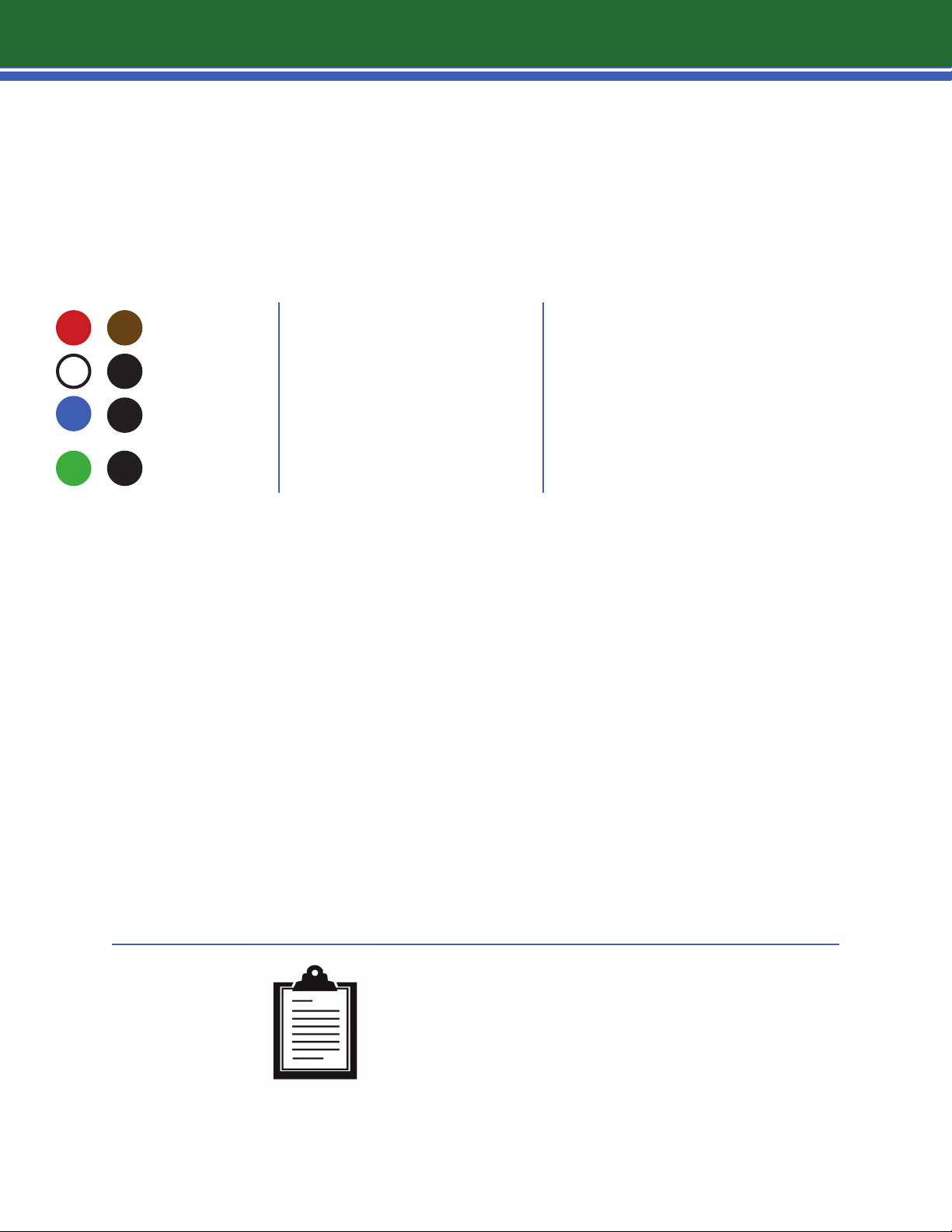
WIRE COLOR PURPOSE CONNECTION
RED|BROWN
WHITE|BLACK
BLUE|BLACK
GREEN|BLACK
FINAL CHECK OF AREA AND PRE-SETTING DECIBEL LEVEL
Again, use the most skilled people for wiring.
It is very important on a large job to check an area (approximately 30 units) before leaving it. Power the
area using one of the transformers. Power with an electric cord, with a plug on one end, and screw
connectors on the other end. Connect power cord to black wires of transformer. Hook wire from home
run to the two screws on the transformer and plug in. Use the sound meter to Test sound level. Find an
area near a Secondary where all of the ceiling tiles are closed to get a reading.
POWER
AUDIO SPEAKER OUT
CVC/RCVC OR TIMER LEVEL
CONTROL
25v|AUDIO in
MAIN (MASTER) to MAIN (MASTER)
MAIN (MASTER) to TRANSFORMER
MAIN (MASTER) to SECONDARY
White wire is used for Secondary only. No other purpose.
ONLY RUN ONE PAIR PER ZONE FROM
MIDDLE OF RUN WHEN USING CVC OR TIMER
AND MASTER TO MASTER
ONLY RUN ONE PAIR FROM MIDDLE OF
RUN TO AMPLIFIER WHEN USING
PA|MUSIC AND MASTER TO MASTER
The ideal reading is between 47.5 and 48 dB. If this is not the level of the sound, adjust using the middle
volume control or if you have a CVC and all of the Mains were preset, you can do the final adjustment for
the whole area from the CVC. Allow to run for approximately 15 minutes. If the transformer overheats or
you can hear a loud humming sound, you have Incorrectly wired unit(s).
NOTE
It may be necessary for you to make 2 or more additional
trips to ne tune the project once the space is furnished.
a great sound makes no noise
section 1
4
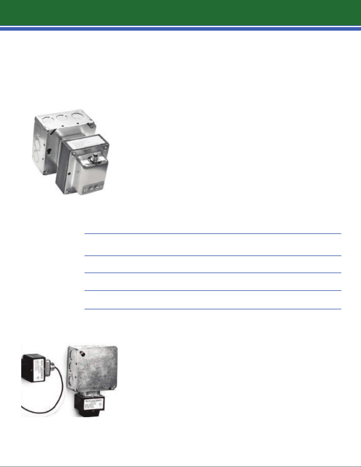
1.3 | hooking up the transformer
HOOKING UP THE TRANSFORMER
Power is to be connected by an electrical contractor. Installer to provide
a UL 1411 recognized transformer with an output of 16/18 volts. Use 16-
18 volt step down transformers. These are designed to be connected to
junction boxes. There is a knock out plug on the side of the junction box:
for the smaller 40va transformer. Several transformers can be connected
to a junction box if you are bringing all of the home runs to a central
area. A sep arate circuit is recommended.
TRANSFORMER CAPACITY CHART*
All transformers 16|18 v 40va 95va
Masking Only no page 33 units 78 units
Masking with moderate paging levels 21 units 48 units
Masking with maximum paging levels 12 units 33 units
* All capacity information assumes a ratio of one main to two secondary speakers.
Junction Box measures
4 inches square, 2 1/8 inches deep
POWER REQUIREMENTS
FOR SOUND MASKING TRANSFORMERS
Please hav
amp circuits in a 4-inch square box (see sample).This electrical
box should be installed above the acoustical ceiling in the
cubicle area or in a centrally located electrical closet.
Typically, one standard junction box can handle up to
(4) 40va transformers
specify and have your electrician install enough junction
boxes to accommodate the number of units for your specific
project.
e your electrician install one or more 120 volt/20
or (1) 95va transformer. Be sure to
section 1
5
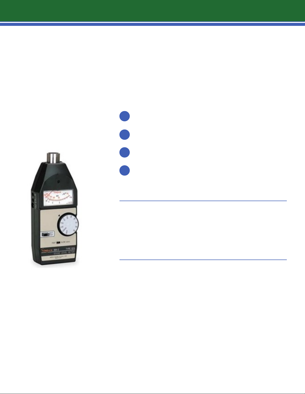
1.4 | sound meter
instructions for using the simpson model 884-2
(or equivalent sound meter)
1
Turn large round dial to 50.
Make sure fast/slow setting is on slow.
2
Hold meter approximately 4’ above floor.
3
Note meter reading after one minute.
4
It takes approximately 30 seconds for meter to respond to sound. 0 to
50 dB...you want the reading to be to the left of the 0. -10 would be 40
dB. You need a reading between -2.5 and 1.5 on the meter. This would
be 47.5 to 48.5dB. It would naturally be high with the ceiling open.
Approximately 2 weeks after install, or when ceiling tiles
and furniture are all in place, reset units to 47.5 to 48.5 dB
four feet above oor.

section 2
6
2.1 | troubleshooting
common questions
LOUD NOISE COMING FROM MAIN (MASTER) AND SECONDARY
This means that there is a miswire. Go to Main and recheck wiring, as it probably is
a ground wire problem. Walk the area and listen for a loud humming sound. In many
cases, this will indicate which unit is miswired.
TRANSFORMER OVERHEATING ?
As in the above scenario, you have incorrectly wired unit(s) and need to search
out the source. Again, walk the area and listen for a loud humming sound. The Main
unit humming is the one wired incorrectly . Power half of the Mains, if the transformer
doesn’t overheat, the problem is in the other half. Check each of the remaining Mains
wires or split the area in half again. There is always a slight possibility that a Main
(master) has the short and it’s not the wiring.
NO SOUND IN AN AREA?
Check the wires as they may not be connected correctly or may not have good contact.
If that is not the case, you have a bad Main. Before you replace the Main, test a second
time with test cord and transformer separately.
IMPOSSIBLE TO HANG UNIT WHERE DRAWING SHOWS?
If an obstacle is in the way, move the unit to the nearest area on the drawing
where an obstacle does not exist.
HOW FAR ABOVE CEILING SHOULD UNITS BE HUNG?
The units should be reachable from a standard 6-8’ ladder. A minimum of 10” above the
ceiling tile is recommended. Most importantly, the units must be hung at a uniform
height throughout the space for correct tuning.
WHAT IF THE AREA TO HANG UNITS HAS A LIGHT OR GRATING?
Move to the next acoustical tile and hang the unit there. Always hang units over
acoustical tiles.
WHAT HAPPENS WHEN YOU HANG A UNIT CLOSE TO AN AIR RETURN OPEN GRILL
OR ANY AREA WHICH ALLOWS THE MASKING SOUND TO PASS FREELY THROUGH
WITHOUT THE CEILING TILE FILTERING THE SOUND?
Sound blends into the existing masking sound in the environment. By doing this
you have taken out the harsh sound that has passed through the ceiling unfiltered.

section 2
7
2.1 | troubleshooting
cvc questions
LOSS OF POWER IN UNITS WHEN HOME RUN IS CONNECTED TO CVC?
Make sure that you have connected the brown & red wires in addition to the blue &
black wires . Make sure you have NOT connected the white wire between the CVC and
a Main. (White wire is only used when connecting a Main/CVC to a Secondary). Recheck
wiring of CVC. If everything checks out- you may have a bad CVC.
HOW DO YOU CONNECT A CVC?
Connect the CVC to a Main near the middle of a run the way you would connect any
other Main. Refer to the appropriate wiring diagram for the correct CVC wiring.
CAN YOU HOOK-UP SECONDARYS TO A CVC?
Yes, a CVC is treated like a regular Main in area it is placed. When doing this we
recommend hooking up only one Secondary to a CVC. Refer to the appropriate wiring
diagram for the correct eve wiring.
timer questions
IF A PROGRAMMABLE TIMER HAS BEEN INCLUDED IN YOUR PROJECT , PLEASE
CONSULT THE TIMER MANUAL. (CVC’S ARE NOT REQUIRED WHEN USING A
PROGRAMMABLE TIMER).

section 2
8
2.1 | troubleshooting
questions about the PA system
WHAT WIRE PATTERN IS REQUIRED TO HOOK UP THE PA SYSTEM?
Use the green and black wire.
IF YOU DON’T WANT THE PA IN A CERTAIN AREA?
Do not hook up the green wire of the Main (master) to the run of Main (master) cable for
the area that you do not want to be connected to the PA. The only consideration is that
the Secondary speakers wired from the non-connected Main (master) are not going to
have PA capability as well. The green wire must be connected from one run of the Main
cable to the next or the PA connectivity will stop there. Also , there is an adjustment
for paging volume on every Main. This will give you further flexibility to turn the page/
music up or down or o.
WHAT TO DO IF THE SOUND IS DISTORTED?
There are two main causes and both of them are simple to fix.The most common solution
is that the volume of your amplifier is too loud. The volume control is very sensitive.
Slight turns can make a great deal of dierence. If the distortion is only in a single area,
more than likely you have a unit hanging at an angle. Rehang so that it is straight.
WHAT TO DO IF SOUND DOES NOT COME ON?
Did you turn up the volume to the amplifier? Is the amplifier plugged in? Ist
amplifier turned on?
WHAT IF THE SOUND MASKING VOLUME GOES DOWN WHEN THE PA IS USED?
Check that there are the correct number of units per transformer.
WHAT IF THE PA DOES NOT WORK IN AN ENTIRE SECTION OF UNITS?
The home run of that area has not been run to the amplifier.

Each Main (master) unit (LM6) and eve unit (LM6-CVC) has a paging/ music input. This is the GREEN wire
9
(25V) and BLACK wire (COM). Both units also have a paging volume control. This control is factory set
in MID position. Connect the GREEN wires of all Mains and eves of a particular paging zone together
to create a home run. Do the same for the BLACK wires . Connect this home run to the 25-volt output
terminal of the paging power amplifie . GREEN to 25V, BLACK to COM.
MICROPHONE PAGING INPUT CONNECTIONS
APFR-20 AMPLIFIER EXAMPLE
MC|TEL selector switch in MIC position
Microphone Hi
Microphone Lo
connect to MIC|TEL INPUT terminal HOT
connect to MIC|TEL INPUT terminal COM
Microphone Shield connect to MIC|TEL INPUT terminal G
See APFR-20 instructional manual for muting options.
In order to utilize a telephone paging system, a telephone interface module is required. This can be a
BSS03, BSS06, BSS09, or other telephone decoding system.
TELEPHONE PAGING INPUT CONNECTIONS
MC|TEL selector switch in TEL position
RING from trunk card connect to MIC|TEL INPUT terminal HOT
TIP from trunk card connect to MIC|TEL INPUT terminal COM
Optional: FRAME ground shield connect to MIC|TEL INPUT terminal G
CHOOSE APPROPRIATE MODULE TYPE FOR MUTING OPTIONS NEEDED
L-01S no muting
L-01S
module can be muted
L-41S voice activated muting of other module
In installations where paging is not utilized and the GREEN wire is not connected, the paging volume control should
be set to minimum position (i.e., counter clockwise) in order to avoid stray electrical noise pickup.

APFR-20 AMPLIFIER EXAMPLE...
10
MUSIC, TAPE, CD INPUT CONNECTIONS
1Ok-ohm, balanced.
Use two conductor shielded cable.
Hi from player connect to H terminal HOT. Lo from player connect to C terminal COM.
GND shield connect to terminal G.
RCA phone plug, 10K-ohm unbalanced. Use two single conductor shielded cables.
Connect left channel to top AUX phone plug and right channel to bottom AUX phone plug.
See APFR-20 instruction manual for muting options.
With the various paging amplifiers and input/output modules, one can design zone
paging, all call paging with mutable background music. For maximum versatility, zone
and all call paging should be provided through the telephone interface module and
should be done by the customer ‘s telephone system installer. Lencore does not
provide this service.

materials required
11
common questions
Cable shall be 18 gauge,Stranded ,UL Listed, Plenum Rated,
1
non shielded.
2
Transformer shall be UL 1411 Listed with an output of 16/18volts.
Fuse shall be UL Listed 3.0 amps installed at each 40va transformer, 125 volts (Max)
rating. Fuse holder shall be UL Listed with same rating. Not required for installations
3
using 95v a transformers due to built-in circuit breaker.
4
Wire nuts & caddy clips.
OPTIONAL EQUIPMENT
Ramset or Hilti Gun (for deck installation)
Telescopic Pole (15’ extension)
Estimate approximately 20’of wire per unit,allowing additional footage for home runs to
NOTE
transformers and/or other equipment such as CVC’s,Timers, Amplifiers, etc.
Wire can be purchased in full rolls of 1,000 feet. Standard layouts will require that twothirds of wire purchased be 2-conductor and the balance of wire pur chased can be two,
four, or six conductor depending on applications used.
CONTROLS TO ADJUST THE MAIN (MASTER) UNIT.
PHOTO SHOWS BOTTOM OF UNIT.

12
section 3
3.1 | schematics
1 POWER ZONE, NO CVC OR TIMER, NO PAGE|MUSIC
1 POWER ZONE, 1 CVC, NO PAGE|MUSIC (AND RCVC OPTION)
1 POWER ZONE, NO CVC OR TIMER, 1 ZONE PAGE|MUSIC
1 POWER ZONE, 1 CVC, 1 ZONE PAGE|MUSIC
2 POWER ZONES, NO CVC OR TIMER, NO PAGE|MUSIC
2 POWER ZONES, 1 CVC,ALL ZONE PAGE/MUSIC
2 POWER ZONES, NO CVC OR TIMER, ALL ZONE PAGE|MUSIC
2 POWER ZONES, 1 CVC, NO PAGE/MUSIC
2 POWER ZONES, 2 CVC’s, NO PAGE/MUSIC
2 POWER ZONES, 1 CVC,NO PAGE/MUSIC
2 POWER ZONES, NO CVC OR TIMER, 2 ZONE PAGE|MUSIC
FIGURE A
FIGURE B
FIGURE C
FIGURE D
FIGURE E
FIGURE F
FIGURE G
FIGURE H
FIGURE I
FIGURE J
FIGURE K
1 POWER ZONE, 1 TIMER, NO PAGE|MUSIC
1 POWER ZONE, 1 TIMER, 1 ZONE PAGE|MUSIC
2 POWER ZONES, 1 TIMER TO ALL ZONES, ALL ZONE PAGE|MUSIC
2 POWER ZONES, 2 ZONE TIMER, NO PAGE|MUSIC
2 POWER ZONES, 2 ZONE TIMER, ALL ZONE PAGE|MUSIC FIGURE P
*POWER ZONES ARE ZONES FOR POWER VIA TRANSFORMER(S)
FIGURE L
FIGURE M
FIGURE N
FIGURE O

schematics
1314151617181920212223


24

Lencore Acoustics Corp.
1 Crossways Park Drive West
Woodbury, NY 11797
516-682-9292
info@lencore.com
www.lencore.com
The information contained herein is proprietary to Lencore Acoustics Corp. and copyright protected. No part of this manual can
be copied, used or distributed without prior authorization from Lencore Acoustics Corp. ©Copyright 2015 REV1003-15-3
 Loading...