

Page 1
OPERATIONS
MANUAL
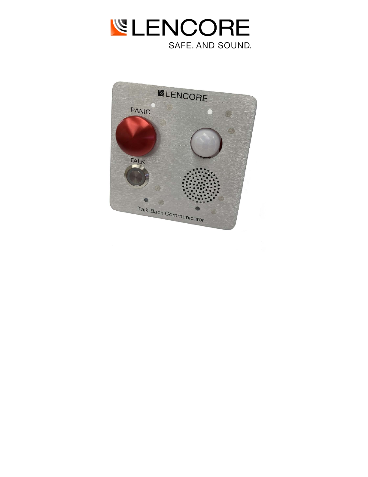
TALK BACK COMMUNICATOR
Document number: 200-0011 rev C
Page 2

table of contents
General operation: .................................................................................................................................. 1
Features and Capabilities:........................................................................................................................ 2
Installation Details: ................................................................................................................................. 3
Overview ................................................................................................................................................. 6
Wiring ..................................................................................................................................................... 8
Power and Network connections: ........................................................................................................ 9
UPS connection: .................................................................................................................................. 9
Configuring the System .......................................................................................................................... 10
Using the System .................................................................................................................................... 10
Paging ................................................................................................................................................. 10
Panic: .................................................................................................................................................. 10
Occupancy sensor: ............................................................................................................................... 10
High Ambient Noise Sensing: ............................................................................................................... 10
Microphone peak detection:................................................................................................................ 11
Variable gain: ...................................................................................................................................... 11
Speaker relay: ...................................................................................................................................... 11
In the event of trouble, please contact:
Name:
Address:
Phone Number:
Page 3

IMPORTANT SAFETY INSTRUCTIONS
RISK OF ELECTRIC SHOCK- DO NOT OPEN THE UNIT.
THERE ARE NO SERVICABLE COMPONENTS INSIDE.
1) Read these instructions.
2) Keep these instructions.
3) Heed all warnings.
4) Follow all instructions.
5) Do not use this apparatus near water.
6) Clean only with dry cloth.
7) Do not block any ventilation openings. Install in accordance with the manufacturer's
instructions.
8) Do not install near any heat sources such as radiators, heat registers, stoves, or other
apparatus (including amplifiers) that produce heat.
9) Protect the power cord from being walked on or pinched particularly at plugs, convenience
receptacles, and the point where they exit from the apparatus.
10) Only use attachments/accessories specified by the manufacturer.
Refer all servicing to qualified service personnel. Servicing is required when the apparatus
11)
has been damaged in any way, such as power-supply cord or plug is damaged, liquid has
been spilled or objects have fallen into the apparatus, the apparatus has been exposed to
rain or moisture, does not operate normally, or has been dropped.
12)
WARNING To reduce the risk of fire or electric shock, do not expose this apparatus to rain
or moisture and do not expose to dripping or splashing and no objects filled with liquids,
such as vases, shall be placed on the apparatus
The mains plug or appliance coupler shall remain readily operable.
Page 4

System: G8254 Talk Back Communicator
- At least one UPS and batteries should be used to provide secondary power supply for
emergency purposes
- The G8254 should be installed using:
1)
Use four 6-32 x 1/2, black, stainless steel pan-head machine screws to mount the unit
to a junction box at least 2-1/8" deep.
Note: An NRTL (UL/ETL) listed double gang box must be used.
- The system is provided with a Communication Security Level 0, which indicates no Security
Level employed.
- The system is not to be used in buildings providing Suppression Service (Systems using Halon, etc).
Sprinkled systems are allowed.
Page 5

General operation:
1
The Talk Back unit is a two-way communications device that allows for dialog between a remote area, such
as a classroom or stairwell, and a central monitoring area, such as a security office. It is not a typical
intercom, and as such does not communicate between Talk Back units. The typical use case is one in
which there are speakers installed in the area of the Talk Back unit and the security office. When the user
presses the “Talk” button on the Talk Back unit a special page is generated on zone 100. The speakers in
the security office are part of zone 100 and will then play the audio from the Talk Back unit. After the user
releases the button, the page is ended. The security office then does a zone override page to the zone that
the Talk Back unit is in. In this way the security office page only goes to the speakers in the Talk Back area.
To prevent other Talk Back units from paging at the same time, the “Talk” button will go red on all other
Talk Back units, and paging is disabled on those units. Only one dialog can happen at any given time. At
the headend, the zone override page is handled by the six “Zone Override” buttons.
The Talk-back unit works with Lencore's G8220 Head-End rack unit.
Page 6

Features and Capabilities:
2
• Page. Pressing and holding the TALK button initiates a page to a central monitoring area
(zone 100)
• Panic. Pressing the panic button sends a trigger to the headend to alert the security staff of an issue
in a particular area.
• Occupancy Sensor. Embedded in the unit is a Passive Infrared Sensor (PIR) that monitors
the area around the Talk Back unit and keeps a historical log of activity.
• High Ambient Noise Sensing. The Talk Back unit includes a microphone that is specially designed
to detect very loud noises such as gun shots or other abnormally loud noises.
• Microphone Peak Detection. Both microphones have peak detection circuits that allow
the headend to monitor peak values for a given time period.
• Variable gain. Both microphones have variable gain circuits that allow the headend to
choose whether to use standard gains or ultra-high sensitivity mode.
• Speaker Relay. The speaker relay connection goes to a special Lencore Speaker that is
relay activated.
Page 7

Installation Details:
3
The Talk Back unit is installed in a standard 4x4 NRTL (UL/ETL) listed double gang switch box using four
6-32 x ½ black stainless-steel pan-head screws. A switch box is required as the 4 mounting screws line up
with holes that are only present on a switch box. The box needs to be at least 2-1/8” deep. The cabling must
exit the junction box on the lower right-hand corner of the bottom of the box. Sufficient cable service loop
must be present to allow the cables to be connected to the Talk Back unit and then fed out of the box as the
Talk Back unit is mounted. When an in-wall switch box is used, this extra cable can be easily fed into the
wall. If a surface installation is done there typically needs to be a pull box, j-box or other scheme employed
to allow for cable to be pulled in and out of the switch box during installation and removal. An example could
be a secondary 4x4 j-box below the Talk Back unit, connected to the switchbox with a suitable nipple.
The Talk Back units requires a 24v dc power feed from either a Lencore supplied HRP-150-24 power supply
or a Lencore PSM7A battery backed up 24v supply. With either supply a total of 15 units can
be fed off one supply (assuming 16AWG wire at 400 ft max from power supply to the last Talk Back unit).
The ground must be maintained on the Talk Back units, the same way Operating Platforms are wired.
In addition to power, the Talk Back sits on the system databus, and as such has a data in and data out
connection. Data cable: The maximum length of the Data cable is 3000 feet from the head-end to the LAST
device connected to the Data cable. A device can be an OP or talk-back module. The distance from talkback to talk-back is not relevant if the previous statement is met. To extend the data cable, adding a router
after the LAST device allows the Data cable to run another 3000 feet from the router.
See the flow diagram below (figure 1).
Page 8
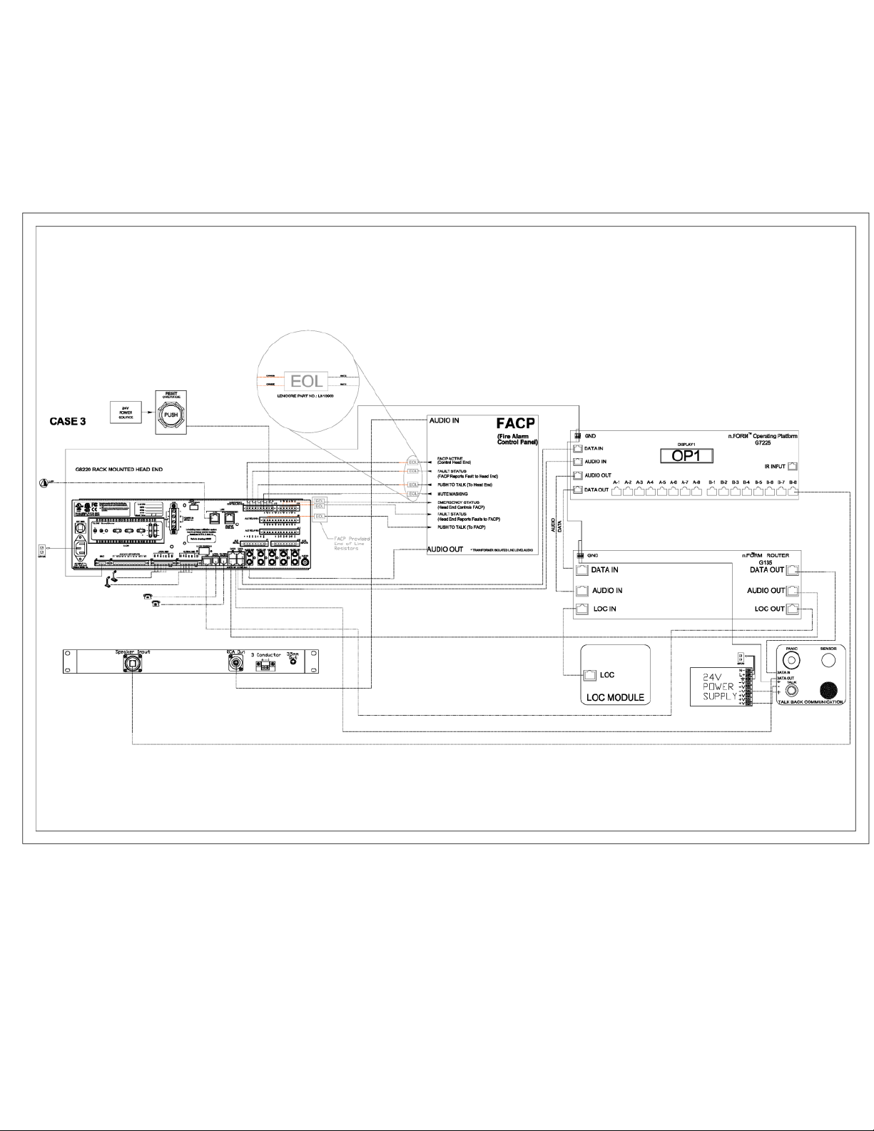
Flow diagram
4
Page 9
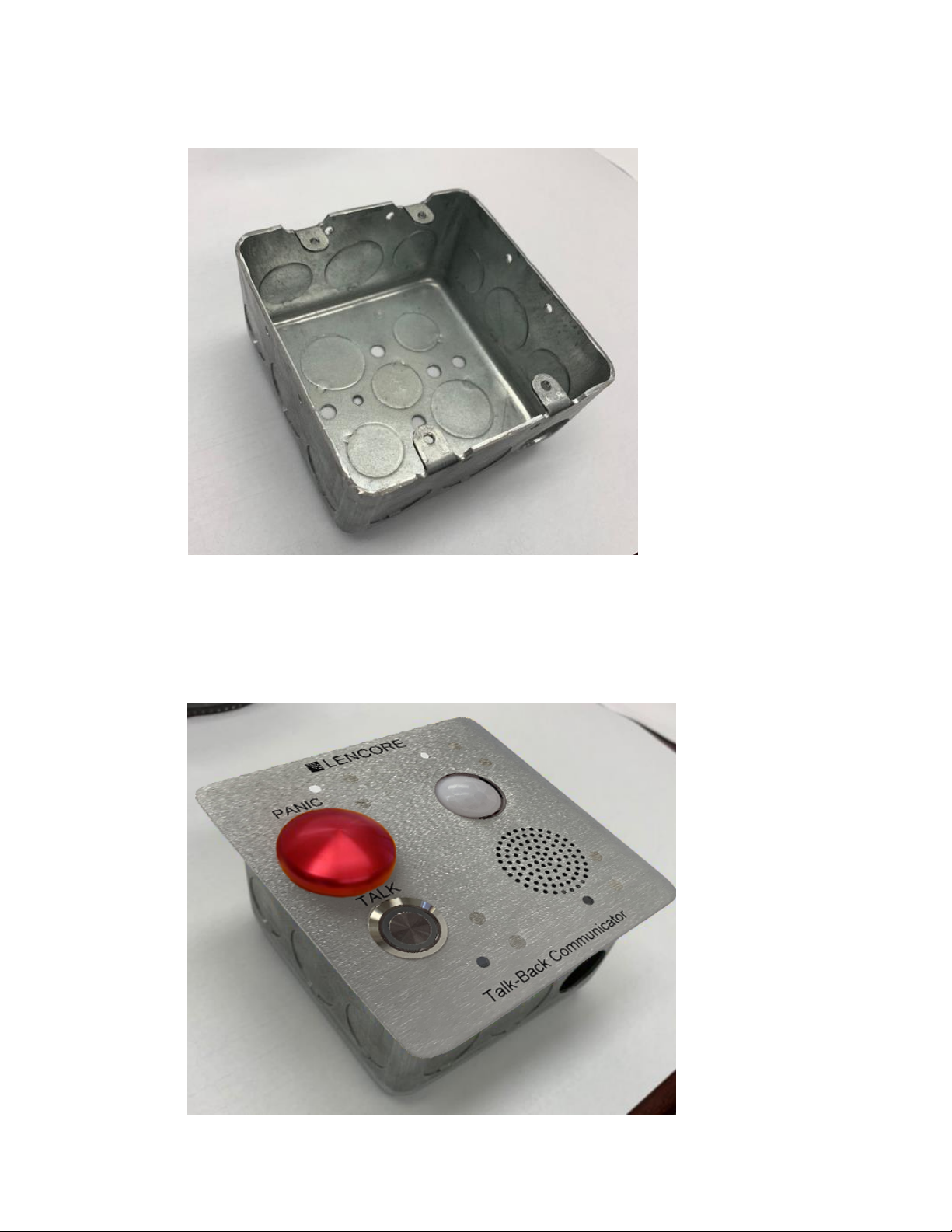
Typical 4x4 junction box:
5
Talk Back mounted in the junction box:
Page 10
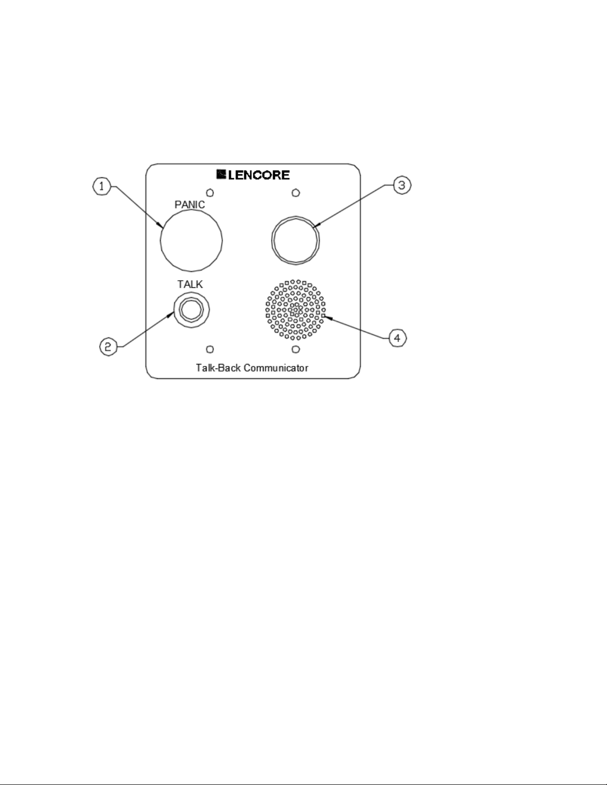
Overview
6
Front Plate
1.
PANIC button
The panic button can be pressed to
send a page alert to the central
monitoring area.
2.
TALK button
The talk button can be pressed to
make a page to the central monitoring
area.
3.
Motion Sensor
The motion sensor senses motion in the
room and can be monitored by the central
monitoring area.
4.
Microphone
While pressing the talk button, speak into
the microphone to make a page to the
central monitoring area.
Page 11
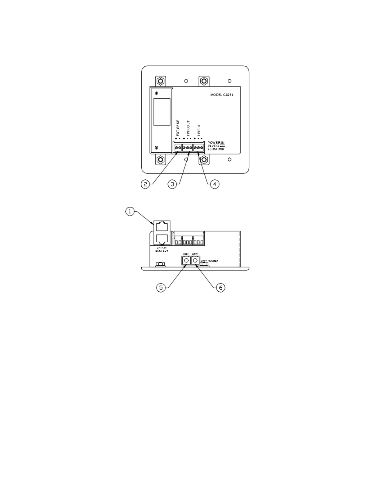
Overview
7
(supervised by UPS)
(supervised by head-end)
(not supervised)
(supervised BY UPS)
Rear Plate
1. DATA IN/OUT ports
Connect the Data out port to the
next OP or Talk Back module.
The Data in port receives the data cable
from the previous OP or Talk Back module.
2. EXT SPKR
speaker (optional) to this connector.
3. PWR OUT
The power out connector is used to power
additional Talk Back units.
Connect a special Lencore
4.
PWR IN
The power in connector receives power from
an external 24VDC power supply.
UNIT NUMBER (HIGH)
5.
The high unit number sets the
sets first first digit of the unit number.
6.
UNIT NUMBER (LOW)
The low unit
digit of the unit number.
number sets the second
Page 12
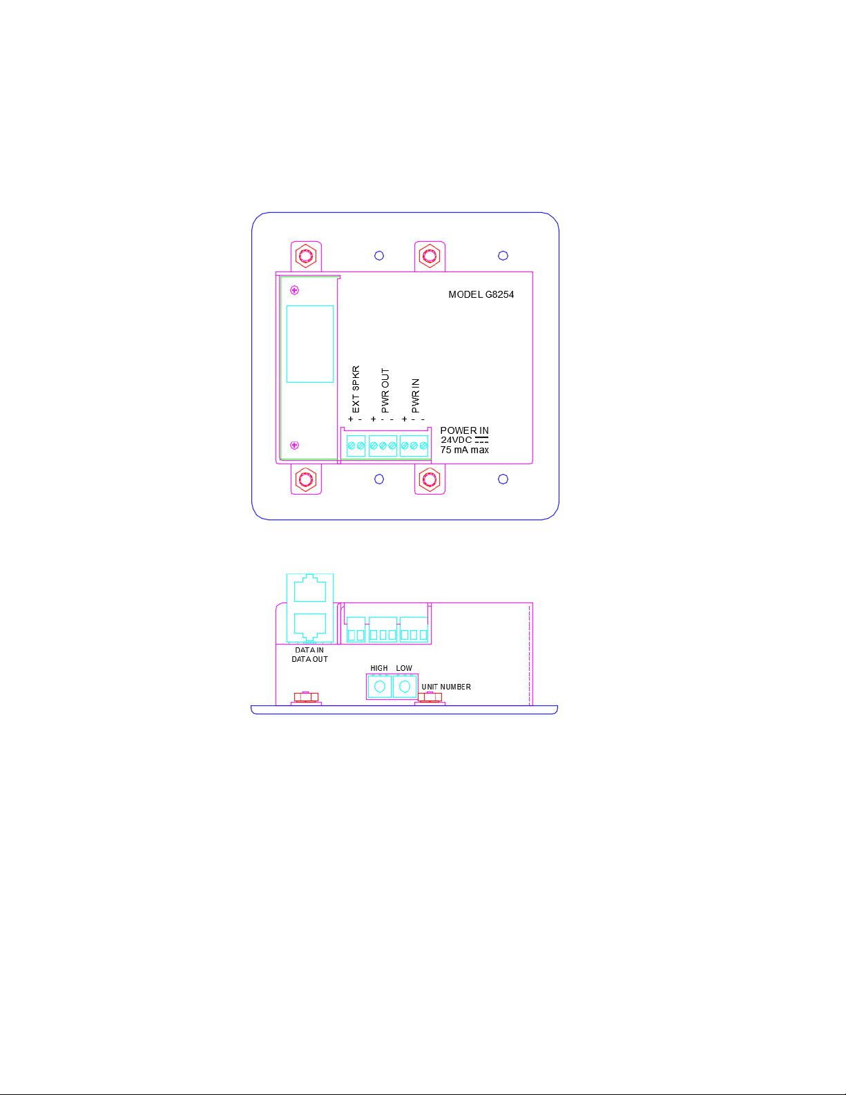
Wiring
8
Power and Network connections:
1. The unit is powered by an external 24VDC power supply. The external power supply’s positive 24VDC
output is wired to the Talk Back’s positive (+) terminal on the PWR IN terminal block The external power
supply’s negative 24VDC output is wired to the Talk Back’s negative (-) terminal on the PWR IN terminal
block.
2. Connect the data cable from a previous OP DATA OUT or router DATA OUT to the Talk Back’s DATA
IN port Connect a cable from the Talk Back’s DATA OUT port to the next OP DATA IN or to the next Talk
Back module’s DATA IN or to the head-end DATA IN in connector.
3. The PWR OUT terminal block can be used to power additional Talk Back units. A total of 65 units can
be powered by the same external 24VDC power supply.
Page 13

Wiring (continued)
9
Power and Network connections:
4. Connect a wire from the previous OP or router negative (-) terminal to either of the Talk Back
PWR IN negative (-) terminals.
5. The EXT SPKR is available to connect a special Lencore external speaker. Do not attempt to
connects any other speaker to this connection or damage to the Talk Back module may occur.
Wiring Type and Gauge:
Data In/Out, Audio In/Out, LOC In /Out: Cat5e
FACP wiring: 16 AWG
24VDC power: 16 AWG
GND: 16 AWG
- All wire to be UL listed, 150V or greater
* Any wire installed in the plenum must be plenum rated.
UPS connection:
The UPS output would connect to the terminal block: +24VDC to pin “+” and 24V COM to either pin “-“. Use a
UL 864 listed power supply for the UPS. The UPS must be 24VDC regulated until the power supply batteries
are exhausted. Lencore's PSM7A meets these requirements. Incorporate a safety margin into the calculated
amp-hour rating of 20%. Maximum battery amp hour capacity supported by the charger to be 24 hours
minimum. Normal and alarm standby load is 75mA. For US installations, the alarm time period is 15 minutes
and for Canadian installations, the alarm time period is 2 hours.
Page 14

Configuring the System
10
The system must be configured before the Talk Back module can be used.
1. Using System Manager, create a page zone 100 for the Talk Back audio to be heard and set
the volume for each speaker.
2. Set all Talk Back unit numbers to be a unique number from each other.
3. Power cycle the unit for the changes to take effect.
Using the System
Paging
Press and hold the TALK button to make a page to the central monitoring area (zone 100). Release
the TALK button to end the page. If the TALK button is lighted red, another user is currently making
a page. The TALK button must be green to initiate a page.
Panic:
Pressing and releasing the panic button sends a trigger to the headend to alert the security staff of an
issue in a particular area. At that point the security staff would again do a zone directed page to that
Talk Back unit. Once the panic button is pressed a pulsing tone would be heard at the Talk Back unit,
until the security office does the page.
Occupancy sensor:
Embedded in the unit is a Passive Infrared Sensor (PIR) that monitors the area around the
Talk Back unit and keeps a historical log of activity. From the headend you can monitor both live
and historical motion activity. This is helpful in locating areas of the building with human activity.
High Ambient Noise Sensing:
The Talk Back unit has two microphones. One that is used for normal speech for paging purposes, as
described above, and one that is specially designed to detect very loud noises such as gun shots or
other abnormal noises. When a noise in made in the vicinity of the Talk Back unit, the detection circuit
associated with the special microphone triggers an event to the headend. This could yield a call by the
security staff via the paging described above, or a in person investigation, or both.
Page 15

Using the System (continued)
11
Microphone peak detection:
Both microphones have peak detection circuits that allow the headend to monitor peak values for
a given time period.
Variable gain:
Both microphones have variable gain circuits that allow the headend to choose whether to use standard
gains of ultra-high sensitivity mode, which allows the security team to listen in to each Talk Back unit to
locate small sounds within the space. This feature works hand-in-hand with a remote Push-To-Talk
feature that will activate the microphone in a given room, even if no one presses the button. This is
highly beneficial in situations where people may be hiding in the area, and motion detection may not
pick them up, but audible noise can.
Speaker relay:
The speaker relay connection goes to a special Lencore Speaker that is relay activated. This connection
provides a switched 24vdc signal that either activates the local speaker or not. This signal is triggered
by the security office page to the given room. This will allow a signal speaker on a channel of 8
speakers to be enabled, based on the zone/room page. This allows a single OP channel to service
multiple rooms and still be able to enable a single speaker on the run.
Page 16

Testing Procedure
12
Equipment should only be tested by qualified trained personnel. These instructions are meant as
a guide to what testing should take place; it is not an instruction on how to complete the testing.
Refer to the Operations, Sound Manager, and Configurator manuals for detailed information.
Testing should be performed monthly or more frequently if necessary.
1. Test the Talk button and microphone proper paging, clarity, and volume.
2. Test the Panic button for proper function.
3. Test the external speaker output relay for proper operation if it is being used.
4. Confirm that the PIR motion sensor is functioning.
Page 17

Maintenance Procedure
13
Equipment should only be inspected and maintained by qualified trained personnel. These
instructions are meant as a guide to what actions should take place; it is not an instruction on how to
complete the activities.
Maintenance should be performed monthly or more frequently if necessary.
1. Inspect and clean if necessary, the microphone openings.
2. Inspect and clean if necessary, the PIR motion sensor.
3. Ensure that all cables and wires are properly seated in their respective connectors.
Page 18

NOTICE TO USERS, INSTALLERS, AUTHORITIES HAVING JURISDICTION, AND OTHER INVOLVED PARTIES
This product incorporates field-programmable software. In order for the product to comply with the
requirements in the Standard for Control and Communication Units for Mass Notification Systems,
UL2572, certain programming features or options must be limited to specific values or not used at all as
indicated below.
Program feature or
option
Permitted in UL2572?
(Y/N)
Possible settings Settings permitted in
UL2572
Page 19

Revision
Level
Revision
Date
Description of Revision
Revision
Author
A 4/30/19 Initial Release
M. Cook
B
C
7/29/19
10/17/19
Various changes for UL2572/864
9DULRXVFKDQJHVSHU ETL
M. Cook
M. Cook
Page 20

Lencore Acoustics Corp.
1 Crossways Park Drive West
Woodbury, NY 11797
516-682-9292
www.lencore.com
The information contained herein is proprietary to Lencore Acoustics Corp. and copyright protected. No part of this manual can
be copied, used or distributed without prior authorization from Lencore Acoustics Corp. ©Copyright 2019
 Loading...