

LENCO SVB Owner's Manual

WE MAKE THE BEST BOATS BETTER!
The world leader in
trim tab systems &
hatch lift innovation.
Owner's
Manual

LENCO MARINE
1
The contents of this manual are subject to change without notice and do not constitute a commitment on the part of Lenco Marine,
Inc. Every effort has been made to ensure the accuracy of this document. However due to ongoing product improvement and revision,
Lenco Marine cannot guarantee the accuracy of printed material after date of publication nor can it accept the responsibility for errors
or omissions. Lenco Marine will update and revise this document as needed. Reproduction or duplication of the manual, or any part
thereof is prohibited without the expressed written permission of Lenco Marine, Inc. All rights reserved. © 2013 Lenco Marine, Inc.
Lenco Electric Actuators
Contents
Trim Tabs
Overview ................................. 3
Special Conditions ......................... 4
Safety ................................... 4
Installation Instructions .....................5-8
Switch Operation
Operation................................. 9
Switch Wiring Diagram Standard #124SSR ..... 10
Switch Wiring Diagram Indicator #123SC....... 11
Switch Wiring Diagram Dual Ram Indicator ..... 12
Switch Wiring Diagram Double Rocker......... 13
Switch Mounting Template .................. 22
Bennett Marine RetroFit Kit
Installation Instructions ...................14-15
Wiring Diagram ........................... 16
Hatch Lifts
Installation/Operation ...................... 17
Wiring .................................. 17
Mounting ................................ 18
System Parts ............................. 18
Trim Tab Maintenance Tips........................19
Warranty Policy ................................ 20
Glossary ...................................... 21
Switch Template................................ 22
2
Owner’s Manual
Lenco Trim Tabs:
• Electric
• Fuel efficient
• Oil-free
• Environmentally
friendly
CONGRATULATIONS!
You have just purchased the finest trim tab
system in the world! Welcome to the future.
Lenco trim tabs make the single most important difference
in the way your boat rides and performs. They are optional
on some boats but should be as standard as power trim
and tilt. Lenco trim tabs make your boat ride smoother,
drier, faster and with increased safety whether on a small
skiff or a mega-yacht. Our ball screw design makes
our tabs more reliable and twice as powerful as typical
hydraulic trim tabs. Coupled with any of our trim tab
switches, they also perform with instant response which
makes them more precise and user-friendly.
Our goal is to manufacture products that simply make
boating more enjoyable.
Visit our website: www.lencomarine.com
All Lenco Trim Tab products
are CE certified
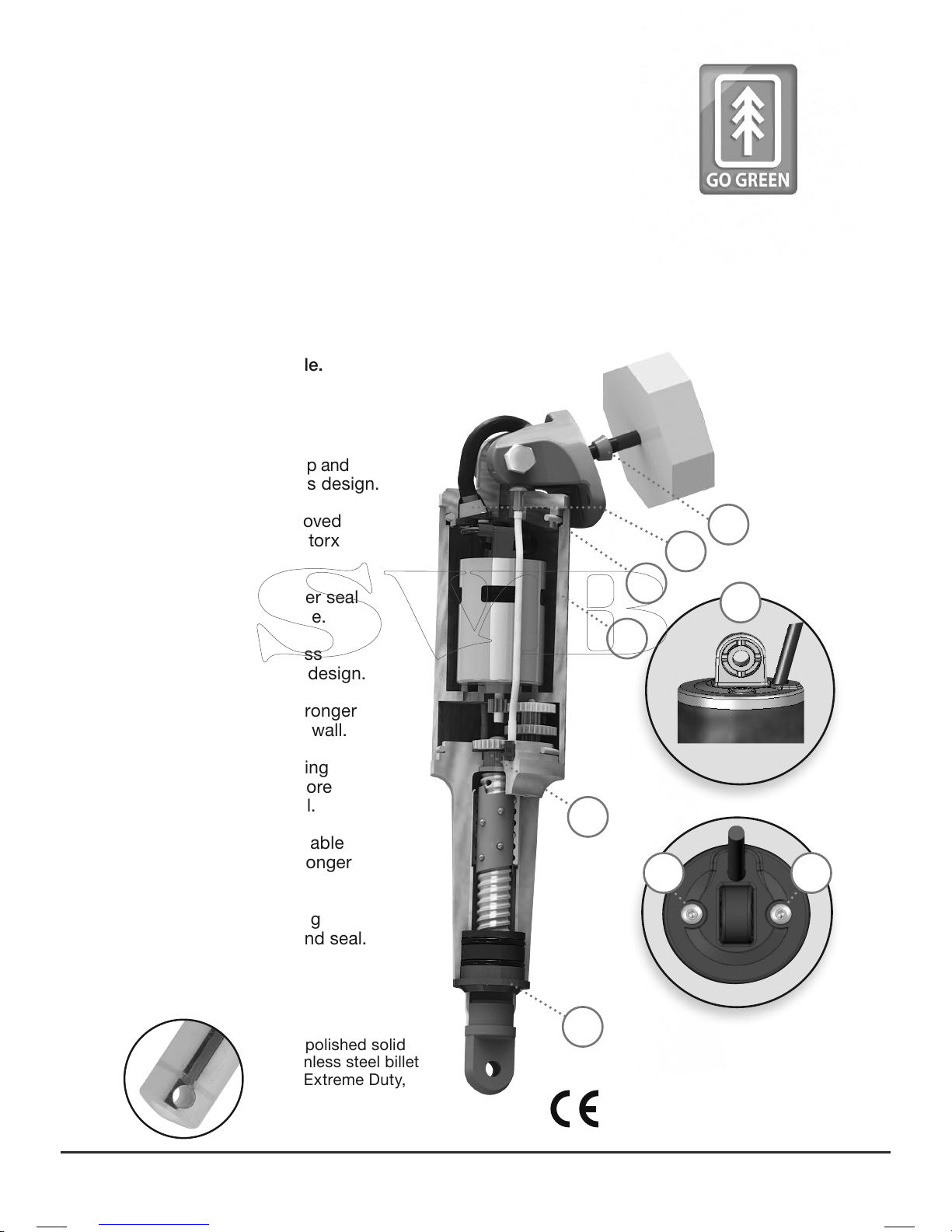
Electro-polished solid
316 stainless steel billet
end for Extreme Duty,
Heavy Duty, and High
Performance applications
1. Stronger top cap and
mounting clevis design.
2.
N
ew and improved
pressure-tight torx
screws.
3. Integrated wiper seal
a
t actuator base.
4.
M
olded-in brass
t
hrust bearing design.
5. Thicker and stronger
motor housing wall.
6. Improved O-Ring
design for a more
consistent seal.
7.
Ov
er-molded cable
providing a stronger
tighter seal.
8.
U
pper mounting
bracket w/ gland seal.
6
7
8
5
4
3
7 8
9
and more durable.
the threaded rod protruding from the actuator cap
providing an improved, pressure-tight seal.
remained from the molding process allowing for a
more consistant seal under extreme loads.
strength by 50% an
d improves symmetry which
strengthens the O-ring seals.
1
3
4
5
7 8
9
and more durable.
the threaded rod protruding from the actuator cap
providing an improved, pressure-tight seal.
remained from the molding process allowing for a
more consistant seal under extreme loads.
strength by 50% an
d improves symmetry which
strengthens the O-ring seals.
support to the gear train and ball screw creating a
smoother, more stable run cycle which decreases
internal wear.
of the actuator provides greater stability during
operation and also serves as a scraper whereby
eliminating particle entry that could potentially
damage internal seals.
o
ver-molded cable feature which eliminates the strain
2 2
LENCO ELECTRIC ACTUATORS
3
LENCO MARINE
Lowers
Starboard
Bow
Lowers
Port Bow
Lenco Trim Tab kits include two stainless steel
planes, two electromechanical actuators and
all mounting hardware for installation (Kits
with backplates do not include mounting
hardware)
. The trim tabs operate independently
of one another to provide optimal performance
by redirecting water flow at the transom of the
boat. Lenco Trim Tabs have been designed to
improve the overall attitude of a boat. If used
properly, Lenco Trim Tabs improve the ride,
reduce drag, increase speed and improve the
fuel efficiency of your boat.
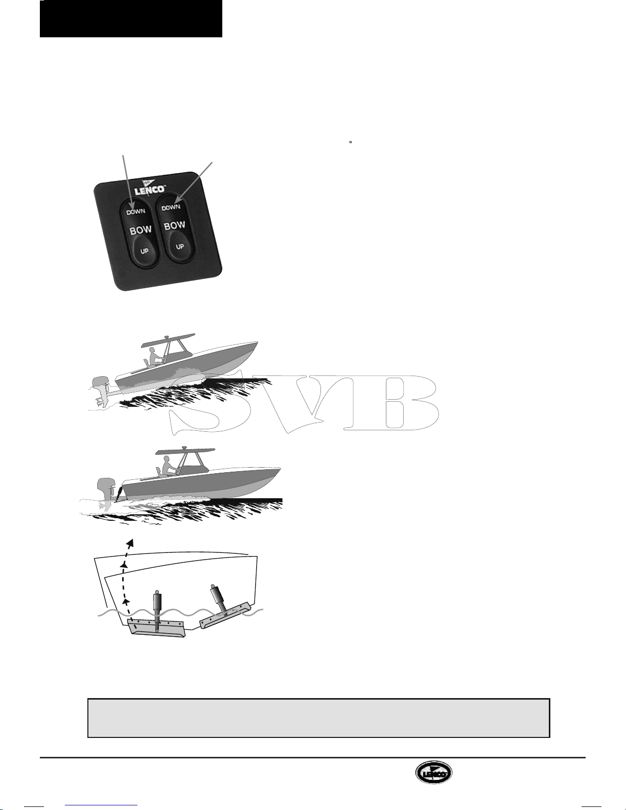
The operation of Lenco Trim Tabs is basic. The
two stainless steel planes are mounted with the
actuators on the transom of the boat. When the
tabs are lowered, the water flow is redirected
creating an upward force at the stern of the
boat. When the stern rises, the bow will lower.
Since Lenco actuators are electromechanical,
they provide an immediate response at the
touch of the switch. This applies to all of our
trim tab switch kits. All Lenco switches are
based on the position of the bow. The left
side of the switch controls the starboard tab.
The right side of the switch controls the port
tab. The system is set up this way to minimize
the guesswork while underway. To lower the
starboard bow, press the right (starboard)
switch where it reads DOWN. To lower the port
bow, press the left (port) switch where it reads
DOWN.
Since all boats are different in weight, length,
speed and performance, it takes practice to
understand how your boat reacts with trim tabs
installed. Lenco Trim Tabs allow your boat to get
on plane faster and continue planing at lower
speeds. This improves visibility and the overall
safety of your boat. When making adjustments
with the trim tabs, use short momentary taps of
the switch.
To become knowledgeable on how your boat
performs with Lenco Trim Tabs, remember,
practice makes perfect.
The Lenco Tactile Switch is
based on the position of the
bow.
When the tabs are lowered,
the water flow is redirected
creating an upward force at
the stern of the boat.
Without Trim Tabs
With Trim Tabs
Lenco electromechanical actuators provide an instant response.
When making adjustments, use short momentary taps of the switch.
Standard
Switch Kit
#124SSR
Trim Tab Overview
Trim Tab Operation

4
Owner’s Manual
Trim Tab Operation
Head Sea —
(Waves or current running directly against
the course of a boat)
Lower both tabs slightly by pressing
BOW DOWN on both sides. This brings bow down while
maintaining speed. This adjustment allows the hull of the
boat to absorb the impact of the waves, resulting in a
more efcient and smoother ride.
Following Sea —
(Waves or current running with the
course of a boat)
Make sure the tabs are fully retracted
by pressing BOW UP on both sides. This brings both
tabs to a fully retracted position decreasing lift in the
stern, allowing the bow to rise. If tabs are deployed, the
bow may dig.
Windy Chop — To raise the windward side of the boat
press B
OW UP o
n that side. If this is not sufcient, press
B
OW DOWN o
n the leeward side of the boat. Do not over
trim when attempting this. This allows the windward side
of the boat to rise and minimizes spray.
Shallow Water/Hole Shot — Lower both tabs completely
down by pressing B
OW DOWN o
n both sides. This
provides lift in the stern of the boat and keeps the bow
down. As you throttle up and speed increases, raise tabs
by pressing B
OW UP o
n both sides.
Uneven Load
—
If one side of the boat is higher than the
other while running, press B
OW DOWN o
n the switch on
that side. This lowers the tab on the listing side (low side)
to bring the boat level.
Porpoising —
(When the bow of the boat leaps clear out
of the water after striking a wave.)
To stop porpoising,
press BOW DOWN on both sides of the switch. The tabs
need only to be deployed slightly to correct this adverse
situation.
• While the boat is underway, do not move one tab up or down signicantly
as this may cause listing.
• While at higher speeds, do not over trim. This causes the bow to lower
quickly, resulting in a reduction of speed and may cause the boat to veer.
• When running in a following sea the tabs should be fully retracted. This
allows for optimal performance.
• While operating trim tabs, use caution. Improper use of trim tabs may
cause accidents and/or injury.
SAFETY
SPECIAL CONDITIONS
HEA
D SEA
FOLLOWING SEA
WINDY CHOP
SHALLOW WATER
HOLE SHOT
UNEVEN LOAD
PORPOISING

5
LENCO MARINE
Trim Tab System Installation Instructions
Warning: The following instructions contain important safety information and should
be followed carefully. Failure to do so may result in injury and will void warranty.
Please read through the instructions in their entirety prior to beginning installation!
Trim Tab Installation Instructions
• Electric drill
• Tape measure
• 3/16" & 3/8" drill bits (.48 & .95 cm)
• 7/16" (1.11 cm) wrench
• 1/2" or 9/16" wrench socket
• Straight edge
• 4' level
• 2" (5.08 cm) hole saw
• #2 & #3 Phillips screwdrivers
• 3M 5200 adhesive caulking
• Wire crimper / cutter
2"
(or more)
2"
(or more)
3/8"
(.95 cm) up from hull
Edge of hinge must be
2" (5.08 cm) from strake
edge in either direction
1" to 4"
in from chine
TRANSOM
FIG.4
Fig. 1
TOOLS AND MATERIALS LIST
Installation of Trim Tab Blades
1. To begin, determine where the Lenco Trim
Tab Kit will be installed. Note: When laying
out the desired tab location, hold the tab
against the transom with the bottom of
the hinge knuckle 3/8" (.95 cm) up from
the bottom of the transom, approximately
1" to 4" (2.54 to 10.16 cm) in from the
chine, and parallel with the hull.
Note: The reason the hinge knuckle
is mounted 3/8" (.95 cm) from the
bottom of the transom is to allow water
to continue to travel freely along the
bottom of the boat past the transom
edge. Tabs are also mounted in this
manner for protection while on a boat
trailer or when being dry-stored.
When mounting the hinge to
the hull make sure that the inside
corner of the hinge knuckle is no
closer than 2" (5.08 cm) to the left or
right of any strake edge. The hinge
may overlap a strake edge as long as
the corner of the hinge knuckle is no
closer than 2" (5.08 cm) to the left or
right of the strake edge (see Fi g.1).
Transfer (trace) the hinge screw hole
pattern onto the transom for drilling.
Note: All Performance Series tabs
with single-tapered blades should be
mounted with the tapered end facing
toward the center of the boat.
2. Using the 3/16" (.48 cm) drill bit, drill
the previously marked hole locations to
a depth of 1-1/4" (3.18 cm).
Note: When drilling out the screw
hole pattern for the trim tab hinge you
may drill through the transom. Hinge
screws should be installed with 3M 5200
adhesive caulking which will seal the
holes. All supplied screws and fasteners
are stainless steel. Do not use any other
type of alloy.
Mount the trim tab hinge to the transom
using provided #14 x 1-1/4" (3.18 cm)
stainless steel sheet metal screws. We
recommend using 3M 5200 adhesive
caulking to bed the hinge and screws.
DO NOT OVERTIGHTEN.
6
Owner’s Manual
Installation of Upper and Lower
Mounting Brackets & Actuators
1. Loosely attach the upper mounting bracket
(bracket with four holes) to the top of the actuator
using the 5/16-18" X 1-3/4" (4.45 cm) large hex
head bolt and 5/16-18 hex nut provided. Attach
the actuator to the lower mounting bracket using
the 5/16-18" X 1-3/4" (4.45 cm) large hex head
bolt and 5/16-18" hex (.79 cm) nut provided.
Attach the lower mounting bracket to the tab with
the bolts, washers, and nylon lock nuts provided
(Kit# 4 - Part# 10000-001) (see Fig. 4).
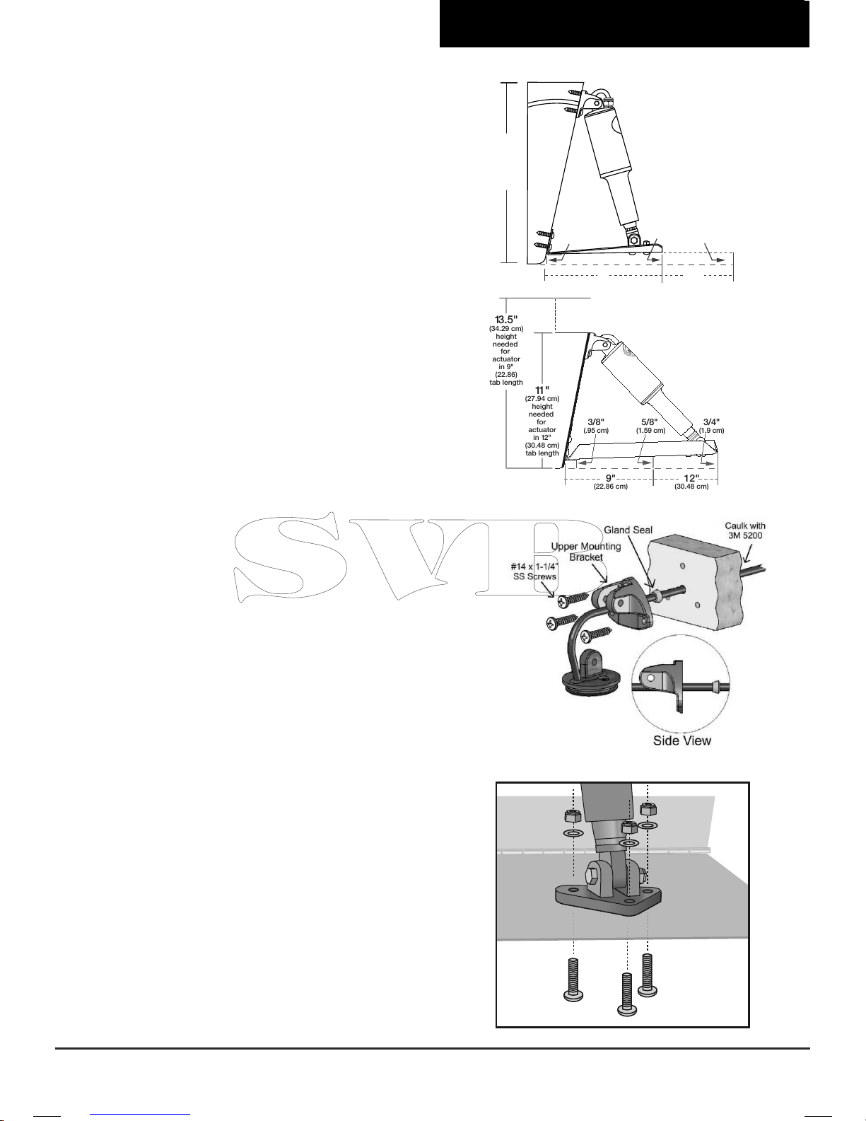
2. In order to properly position the upper mounting
bracket against the transom, you must lift the
trim tab so that the trailing edge is approximately,
5/8" (1.59 cm) for a 9" trim tab and 3/4" (1.9 cm)
for a 12" trim tab, above the straight edge when
held to the hull (see Fig. 2.1 & 2.2). When the trim
tab is at the appropriate level and the actuators
are fully retracted, transfer (trace) the outer shape
of the upper mounting bracket onto the transom.
The upper mounting bracket should be marked
where it lays naturally against the transom to
prevent binding during functioning of trim tabs.
Note: Do not adjust the upper mounting bracket
to the right or left, as this will cause binding.
Allow the bracket to come to rest at its natural
position.
Remove the upper mounting bracket from the
actuator and align to the previously marked
location to mark the upper mounting bracket
screw hole locations and cable hole location.
Using the 3/16" (.48 cm) drill bit, drill the three
previously marked screw hole locations to a
depth of 1-1/4" (3.18 cm).
Warning: With some installations, fuel, water
tanks and/or other systems may prevent the
actuator cable from entering the hull through
the upper mounting bracket. Be sure to check
inside the hull before drilling the 3/8" (.95 cm)
cable hole.
Note: When drilling out the screw hole pattern
for the upper mounting bracket, you may drill
through the transom. The screws should be
installed with 3M 5200 adhesive caulking which
will seal the holes when installed.
All supplied screws and fasteners are stainless
steel. Do not use any other type of alloy.
(Continued on page 7)
Trim Tab Installation Instructions
5/8"
(1.59 cm)
14"
(35.56 cm)
max.
height
needed
for
actuator
3/8" (.95 cm)
9"
(22.86 cm)
3/4" (1.9 cm)
12"
(30.48 cm)
Standard Mount
Fig. 2 .1
Edge Mount
Fig. 2.2
Fig. 3
ANGLE OF THE TAB
5/8"gap
(1.59 cm)
3/8"gap
(.95 cm)
14"
(35.56 cm)
maximum
transom
height
needed
HULL LINE
HULL LINE
9" TAB
(22.86 cm)
3/4"gap
(1.9 cm)
1"gap
(2.54 cm)
12" TAB
(30.48 cm)
16" TAB
(40.64 cm)
2"
(or more)
2"
(or more)
3/8"
(.95 cm) up from hull
Edge of hinge must be
2" (5.08 cm) from strake
edge in either direction
1" to 4"
in from chine
TRANSOM
Bolts enter
from the
underside
of tab
FIG.4
FIG.5
Fig. 4
3/4"
(1.9 cm)
3/8"
(.95 cm)
11"
(27.94 cm)
height
needed
for
actuator
in 12"
(30.48 cm)
tab length
13.5"
(34.29 cm)
height
needed
for
actuator
in 9"
(22.86)
tab length
9"
(22.86 cm)
12"
(30.48 cm)
5/8"
(1.59 cm)

7
LENCO MARINE
If all is clear, use the 3/8" (.95 cm)
drill bit and drill the previously marked
cable hole completely through the
transom. Insert the actuator cable
through the appropriate hole in the
upper mounting bracket until the
mount reaches the actuator. Insert the
actuator cable through the gland seal
until it reaches the rear of the upper
mounting bracket.
Note: For appropriate orientation
of upper mounting bracket and gland
seal, (see Fig 3 on page 6).
If, however, you are prevented from
drilling a hole through the transom at
the bracket location, using the 3/8"
(.95 cm) drill bit, simply drill a 3/8" (.95
cm) hole 4" to 5" (10.16 to 12.7 cm)
above the waterline and insert the
cable. Cover the hole and cable with a
clamshell vent sealed with 3M 5200 for
a waterproof and nished eect.
Insert the actuator cable through the
transom. With the actuator loosely
supported, start the provided #14 x
1-1/4" (3.18 cm) stainless steel sheet
metal screws through the upper
mounting bracket holes and into the
transom. MAKE SURE TO LEAVE
THE SCREWS ONLY PARTIALLY
INSTALLED.
Insert the actuator clevis (mounting
ear) into the upper mounting
bracket and hold the actuator in
the approximate installed position.
Pass the actuator cable through the
transom removing slack on the cable
until it looks like the installation on
F
ig 2.1 on page 6. Finish installing the
previously started #14 x 1-1/4" (3.18
cm) stainless steel sheet metal screws
through the upper mounting bracket
and into the transom. We recommend
using 3M 5200 adhesive caulking to
bed the upper mounting bracket and
screws. DO NOT OVERTIGHTEN.
Attach and secure the actuator to the
upper mounting bracket using the
5/16-18 X 1-3/4" (4.45 cm) large hex
head bolt and 5/16-18 (.79 cm) hex nut
provided.
We recommend using 3M 5200
adhesive caulking to seal the cable
hole on the inside of the transom.
Attach connector ends to the actuator
wire pins as instructed in Actuator
Deutsch Connector Instructions
insert card provided. If using actuator
extension cables, this would be a
good time to run them to the control
box mounting area.
NOTE:
SA
CRI
FICIAL ANODES FOR
YOU
R LENCO SS TRIM T
ABS
Be aware that stray currents in your
marina or in a visiting marina can
cause damage to your trim tab blades
if not protected by sacricial anodes.
• The addition of anodes on each tab
will deter electrolysis.
• Do not paint under the anode or the
anode itself.
• Check Anode condition frequently.
Replace when necessary.
Switch Installation
Installation instructions for Standard
(124SSR), Indicator (123SC), and Dual Ram
Indicator (123DR) Digital Tactile Switches.
1. At the helm, determine where the
tactile key pad will be installed, locate
the template on page 22 and secure
to helm. Cut a circular opening using
a 2" (5.08 cm) hole saw (Hole must
be 2"). Before cutting, make sure the
area inside the helm is clear of wires
and other equipment that could be
damaged. Using the template on
page 22, drill four 3/16" (.48 cm) holes
through the helm.
2. Install the black control box (hardware
not included) within 24" (60.96 cm) of
the key pad hole.
Make sure control
box is mounted on a vertical surface
with wires facing down toward the deck.
Mounting the control box in the incorrect
orientation will void the warranty.
Trim Tab Installation Instructions
Installation Instructions continued from page 6.
 Loading...