

Page 1
OWNER’S MANUAL
• PLL Synthesizer Stereo Radio
• Digital Compact Disc/MP3 Player
• Automatically Memory Storing
• Electronic Detachable Panel
CS-200
Page 2

2
Installation .....................................................................................................3
DIN Front-Mount (Method A) ..................................................................................3
Installing the unit ...............................................................................................3
Removing the unit .............................................................................................4
DIN Rear-Mount (Method B) ...................................................................................4
Using the Detachable Front Panel..........................................................................5
Wiring Connection ........................................................................................6
Operation .......................................................................................................7
General Operation ..................................................................................................7
Radio Operation....................................................................................................10
CD Operation........................................................................................................12
MP3 Operation......................................................................................................13
Specification................................................................................................14
Trouble Shooting.........................................................................................15
Important Remark:
After initial installation you have to press the RESET button (23) otherwise
the unit will not function properly.
CONTENTS
Page 3
3
Notes:
• Choose the mounting location where
the unit will not interfere with the
normal driving function of the driver.
• Before finally installing the unit,
connect the wiring temporarily and
make sure it is all connected up
properly and the unit and the system
work properly.
• Use only the parts included with the
unit to ensure proper installation.
The use of unauthorized parts can
cause malfunctions.
• Consult with your nearest dealer if
installation requires the drilling of holes
or other modifications of the vehicle.
• Install the unit where it does not get in
the driver’s way and cannot injure the
passenger if there is a sudden stop,
like an emergency stop.
• If installation angle exceeds 30˚ from
horizontal, the unit might not give its
optimum performance.
• Avoid installing the unit where it would
be subject to high temperature, such
as from direct sunlight, or from hot air,
from the heater, or where it would be
subject to dust, dirt or excessive
vibration.
DIN FRONT/REAR-MOUNT
This unit can be properly installed either
from “Front” (conventional DIN Frontmount) or “Rear” (DIN Rear-mount
installation, utilizing threaded screw holes
at the sides of the unit chassis).
For details, refer to the following
illustrated installation methods.
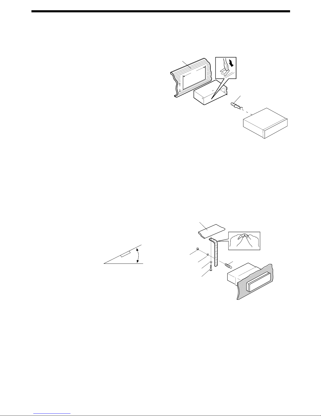
DIN FRONT-MOUNT (Method A)
Installing the unit
1. Dashboard
2. Holder
After inserting the holder into the
dashboard, select the appropriate tab
according to the thickness of the
dashboard material and bend them
inwards to secure the holder in place.
3. Screw
1. Dashboard
2. Nut (5mm)
3. Spring washer
4. Screw (5 x 25mm)
5. Screw
6. Strap
Be sure to use the strap to secure the
back of the unit in place. The strap
can be bent by hand to the desired
angle.
7. Plain washer
30˚
(Fig. 1)
1
3
2
182
53
(Fig. 2)
1
2
6
5
4
3
7
INSTALLATION
Page 4
4
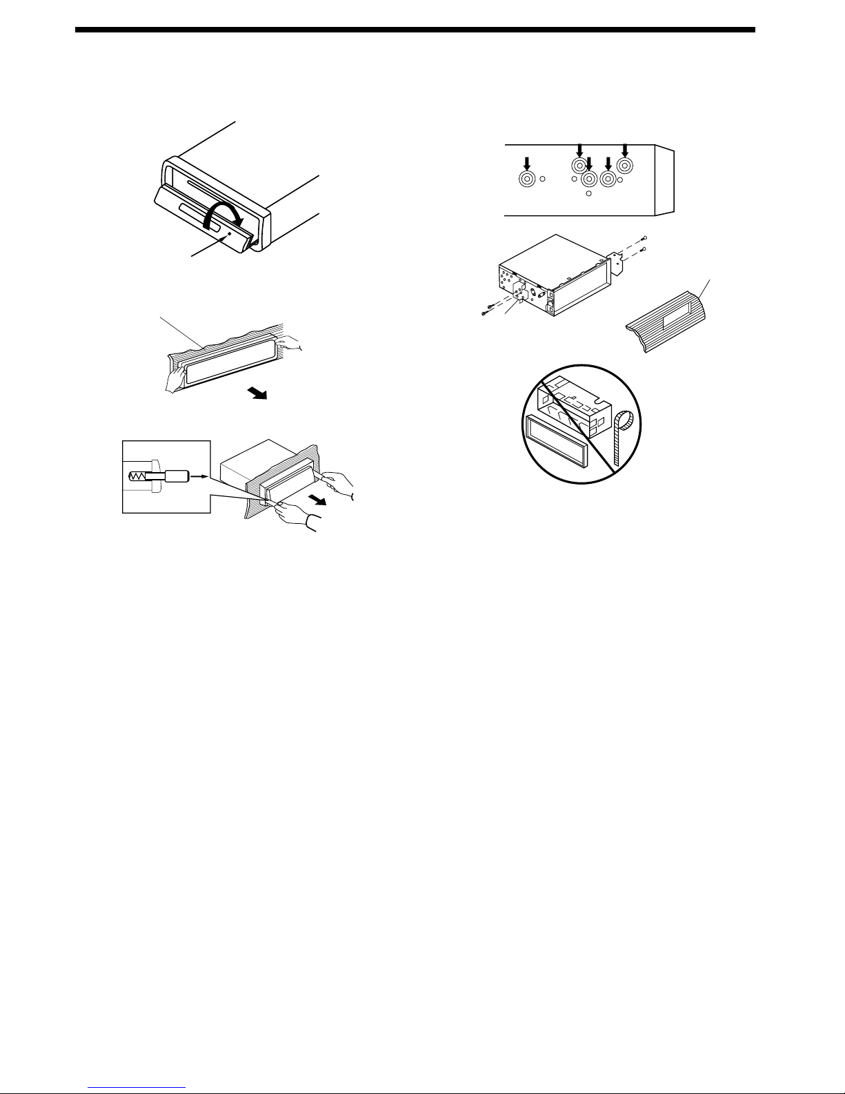
Removing the unit
1. Before removing the frame, press the
OPEN/CLOSE button to slide down
the front panel.
2. Frame
3. Insert fingers into the groove in the
right side of the frame and pull out to
remove the frame. (You can also
remove the frame from the left side.)
4. Lever
After removing the frame, press the
OPEN/CLOSE button again to slide
up the front panel. Then insert the
levers supplied with the unit into the
grooves at both sides of the unit as
shown in figure until they click.
Pulling the levers makes it possible to
remove the unit from the dashboard.
DIN REAR-MOUNT (Method B)
Installation using the screw holes on the
sides of the unit.
Fastening the unit to the factory radio
mounting bracket.
1. Select a position where the screw
holes of the bracket and the screw
holes of the main unit become aligned
(are fitted), and tighten the screws at
2 places on each side.
Use either truss screws (5 x 5mm),
depending on the shape of the screw
holes in the bracket.
2. Screw
3. Factory radio mounting bracket
4. Dashboard or Console
Note: The mounting box, outer trim ring,
and half-sleeve are not used for method
B installation.
3
4
2
2
1
Open/Close
1
2
3
4
INSTALLATION
Page 5
5
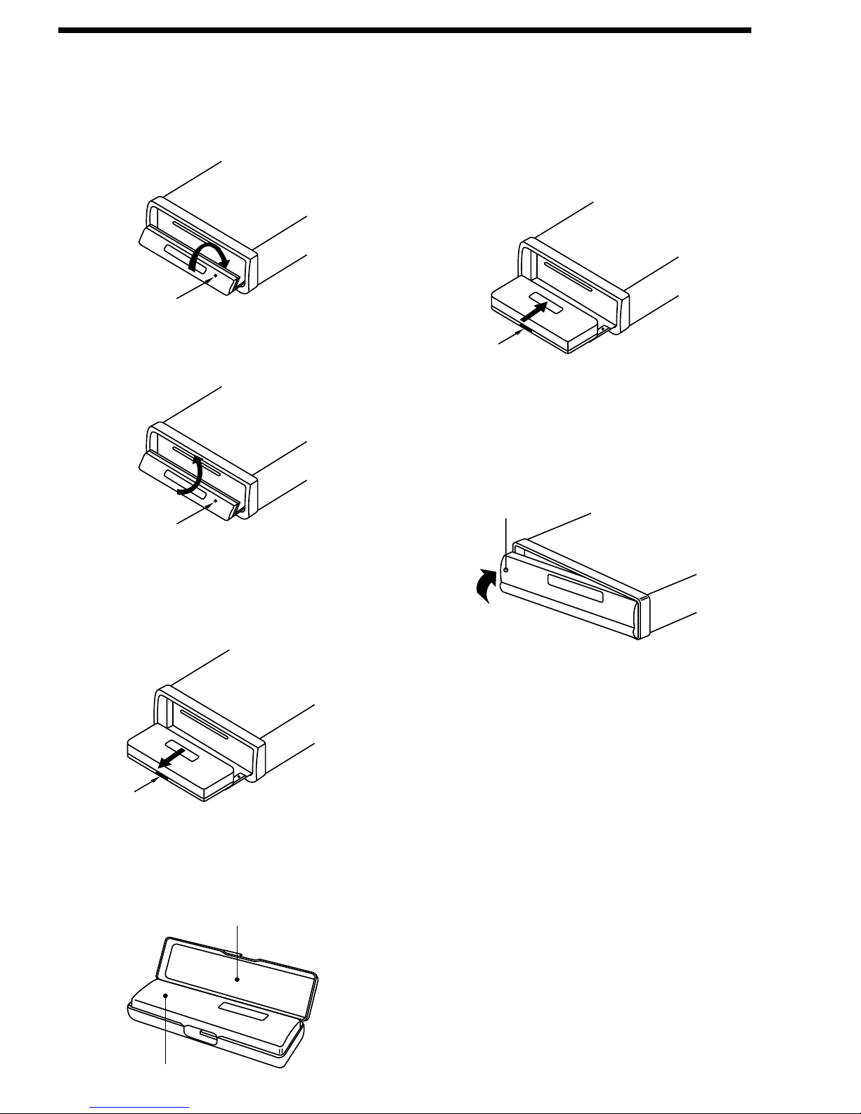
To Reinstall the Front Panel
1. When the panel bracket is in slide
down position, insert the front panel
into panel bracket and press
OPEN/CLOSE button to slide up.
2. When the panel bracket is in slide up
position, insert a side of the front
panel to its proper position and push
another side into the panel bracket, a
‘click’ sound should be heard.
3. Note that if the front panel fails to lock
in position properly, press control
button may not function and LCD
display may be missing some
segments. Press the OPEN/CLOSE
button and then reinstall the front
panel again.
USING THE DETACHABLE FRONT PANEL
To Detach the Front Panel
1. Press the OPEN/CLOSE button, the
front panel will slide down.
2. Press the OPEN/CLOSE button again,
the front panel will slide up.
3. When the front panel slides down,
press the bottom button of the front
panel upward and pull it out from the
panel bracket.
4. For safekeeping, store the front panel
in the supplied protective case
immediately after being removed.
Open/Close
Open/Close
Bottom
Button
Bottom
Button
Protective Case
Front Panel
Front Panel
Page 6

6
WIRING CONNECTION
BLUE
BLUE/BLACK
GREY
GREY/BLACK
WHITE
WHITE/BLACK
MAIN UNIT
GREEN
GREEN/BLACK
FRONT Lch
SPEAKER
REAR Lch
SPEAKER
FRONT Rch
SPEAKER
REAR Rch
SPEAKER
Rch RED
Lch WHITE
(GREY)
REAR RCA CABLE
Rch RED
Lch WHITE
(BROWN)
FRONT RCA CABLE
ANTENNA CONNECTOR
RED
PINK
BLACK
CHOKE
BOX
YELLOW
POWER
ANTENNA
GROUND (B–)
MEMORY
BACK-UP
IGNITION
SWITCH (B+)
Page 7

7
GENERAL OPERATION
• ON/OFF
Switch on the unit by pressing any
button. When system is on, press
POWER button (9) to turn off the unit.
• FACEPLATE RELEASE
Press OPEN/CLOSE button (7) to slide
down the front panel and you can
press it again to slide up the front panel
OPERATION
into the main body or detach the
removable faceplate.
• SOUND ADJUSTMENT
Press SEL button (10) shortly to select
the desired adjustment mode.
The adjustment mode will change in
the following order:
VOL BAS TRE BAL FAD
(Volume) (Bass) (Treble) (Balance) (Fader)
5
14822 18212019 6 9
115 7 4
3
21110
17121613
23
Page 8

For Electronic Volume:
By pressing AUDIO CONTROL
button (11) or AUDIO CONTROL
button (12), it is possible to adjust the
desired sound quality.
For Digital Rotating Volume:
By rotating the knob (11 & 12)
clockwise (CW) or c-clockwise (CCW),
it is possible to adjust the desired
sound quality.
Press SEL Button (10) for several
seconds, it is activated as cyclical
mode of following functions for user’s
selection.
a) TA SEEK or TA ALARM
- TA SEEK mode:
When newly tuned station does
not receive TP information for
several seconds, the radio
retunes to next station which has
not the same station (PI) as the
last station, but has the TP
information.
When TP information gets lost at
the current station for retune time
which is set by RETUNE SHORT
(30 sec.) or RETUNE LONG (90
sec.), the radio start to retune to
next same PI station. When same
PI station does not catch in 1
cyclic search, the radio retunes to
next station with TP information.
- TA ALARM mode:
When this mode is selected, any
automatic retune mode is not
activated. Only double beep
sound (ALARM) is output.
When newly tuned station does
not have TP information for
several seconds, beeps come out.
When TP information gets lost at
the current station for retune time,
the beep sound is out-putted.
When newly tuned station has not
RDS signal, “PI SEEK” is
suppressed somewhat.
8
b) PI SOUND or PI MUTE
While AF switching is implemented
in C201 station, AF can switch to
100 MHz, which is non genuine AF
(where, different PI with same AF) in
short “DIP”.
If a car cruises that critical area back
and forth, an oscillation
phenomenon can be occurred,
because the different PI code can
be received from 100 MHz with
“XXX” PI.
The car radio has special procedure
to reduce even this kind of
unavoidable situation however there
is a limit to be escaped from this
serious case perfectly.
In that serious case, 2 mode is
selectable as follows:
- PI SOUND mode:
When above different PI sound
(DIP) is heard once in a while, the
DIP’s sound will be heard for a
short time.
- PI MUTE mode:
Under above same situation, a
mute sound will be heard for a
short time.
c) RETUNE L, RETUNE S mode
The initial time of automatic TA
search or PI search mode is
selected.
When PI information is not caught
for retune time, the radio start to
retune to next same PI station.
When same PI station does not
catch 1 cyclic search, the radio
goes to last station and waits for
several minutes until PI code is
received.
- RETUNE L mode:
Selected as 90 seconds.
- RETUNE S mode:
Selected as 30 seconds.
TA SEEK or ALARM PI SOUND or MUTE
MASK DPI or ALL RETUNE L or S
BEEP 2’nd, ALL or OFF
100
90
98
100
PI : C201 PI : XXX
OPERATION
Page 9

d) MASK DPI or MASK ALL mode
The AF frequency (which has
different PI or NO RDS signal with
high field strength) is masked during
checking PI when the unit searches
AF. The unit doesn’t search this AF
(DIP) for few minutes. In the case
of the AF of NO RDS signal with
high field strength, if the real AF is
wrongly masked as DIP by some
interference, the unit hesitates to
search real Afs. For this reason, the
unit has the user option (MASK DPI)
which doesn’t mask the AF of NO
RDS signal with high field strength.
In MASK DPI mode, the wrong
sound or long mute (according to PI
SOUND or PI MUTE) can be heard
from the AD station which has NO
RDS signal and of which the field
strength is higher than that of the
currently tuning AF (station).
But, these phenomenon are rare
and the user will hardly hear the
wrong sound in whole Europe.
- MASK DPI mode:
Masked only the AF which has
different PI.
- MASK ALL mode:
Masked the AF which has
different PI and NO RDS signal
with high field strength.
e) BEEP 2’ND, BEEP ALL, BEEP OFF
mode
The situation of beep sound is
selected.
For Electronic Volume:
The 3 mode is selected as also
AUDIO CONTROL button (11) or
AUDIO CONTROL button (12).
For Digital Rotating Volume:
The 3 mode is selected as AUDIO
CONTROL knob (11 & 12).
- BEEP 2’nd mode:
The beep is only generated when
all allowed double key is pressed
long (1 sec).
e.g.
When Preset Button (14) is
pressed.
9
When BND/LOU Button (13) is
pressed.
When AMS Button (18) is pressed.
- BEEP ALL mode:
The beep is generated when every
key is pressed.
- BEEP OFF mode:
The beep is disabled.
• LOUDNESS
Press BND/LOU button (13) for several
seconds to reinforce the bass output.
• DISPLAY
Press DSP button (15) to operate as
the conversion of each display mode
as follows:
- In case of receiving a RDS station
In radio mode: -> PS -> CT ->
FREQ. -> PTY ->
In CD mode: -> CD -> CT -> PS ->
FREQ. -> PTY ->
- In case of no receiving CT or PTY
information, the display shows as
“NO CLOCK” or “NO PTY”.
- In case of receiving a non RDS
station
In radio mode: -> “NO CLOCK” ->
FREQ. -> “NO PTY” ->
In CD mode: -> CD -> CT -> FREQ.
-> “NO PTY” ->
Each displaying time is several
seconds, and come back to 1’st
position after several seconds.
Notes:
- CT = clock time
- FREQ. = frequency
• SELECT MODE
Press MOD button (6) to choose
desired listening mode.
(e.g. radio mode to CD (MP3) mode)
• LIQUID CRYSTAL DISPLAY
Exhibit current frequency and activated
functions on the display (8).
• RESET
Reset button (23) is placed on the front
panel and must be activated with either
a ball point pen or thin metal object.
OPERATION
Page 10

10
The reset button is to be activated for
the following reasons:
- Initial installation of the unit when all
wiring is completed.
- All the function buttons do not
operate.
- Error symbol on the display.
Note: If press RESET button (23), the
unit can’t work yet, please use a cotton
swab soaked in isopropyl alcohol to
clean the socket on the back of the
front panel.
RADIO OPERATION
• BAND SELECTION
At tuner mode, press BND/LOU button
(13) to select the desired band.
The reception band will change in the
following order:
• STATION SELECTION
Press TUNE/SKIP/TRACK / –
button (16) or TUNE/SKIP/TRACK
+ / button (17) shortly to activate
automatic seek function.
Press for several seconds until
“MANUAL” appeared on the display,
the manual tuning mode is selected.
If both buttons have not pressed for
several seconds, they will return to
seek tuning mode and “AUTO”
appeared on the display.
• AUTOMATICALLY MEMORY
STORING & PROGRAM SCANNING
- Automatic Memory Storing
Press AMS button (18) for several
seconds, the radio searches from
the current frequency and checks
the signal strength until one cycle
search is finished.
And then 6 strongest stations are
stored into the corresponding preset
number button.
- Program Scanning
Press AMS button (18) shortly to
scan preset station. When the field
strength level is more than the
threshold level of stop level, the radio
is holding at that preset number for
several seconds with releasing mute,
then searches again.
• STATION STORING
Press any one of the preset buttons
(14) (M1 to M6) to select a station
which had been stored in the memory.
Press this button for several seconds
(until 2’nd beeps come out), current
station is stored into the number
button.
• RDS (RADIO DATA SYSTEM)
OPERATION
- Setting RDS Mode
Press AF/REG button (3) and release
immediately to switch on or off RDS
mode.
Whenever RDS is switched on,
symbol “AF” appears on the display.
Program name is displayed on
receiving a RDS station.
“AF” starts blinking if the
broadcasting signal getting worse.
“ALARM” will be displayed when an
emergency broadcasting is received;
meanwhile sound output level will be
adjusted to the pwreset output level
automatically when the volume
control is set at minimum.
- Regional Program Operation
Press AF/REG button (3) for several
seconds to switch on or off region
mode.
Some broadcasting stations change
their program from normal
broadcasting to regional
broadcasting for a certain time
period.
When region is on, the current
listening program remains
unchanged.
When region is off, it allows the
reception moves to the regional
station.
OPERATION
FM1 FM2 FM3
Page 11

11
Temporary switch over to an EON
linked station when EON detects a
traffic announcement on that other
program.
If the volume level was under the
threshold point it will be raised to the
threshold point. But the user
changed the volume level which was
more than the threshold point (min.
TA volume level), it will be set to the
last level.
When TA mode is on, TA of
individual segment is turned on.
When a TP station is received, TP of
individual segment is turned on.
TA interruption function
The current traffic announcement is
cancelled by pressing this key.
But the TA mode will not be off.
When pressed long, it is selected
EON TA LOCAL/EON TA DISTANCE
mode.
The purpose of this key is to reduce
unwanted EON TA switching, which
EON TA information was received
from current station and the radio
switched to that EON linked station,
but no information could not be
received because the EON linked
station is located too far from that
area. So the radio is switched back
to current station again. In above
operation, a customer listen to a
wrong program or mute sound for a
while.
EON TA LOCAL mode
When the filed strength level of EON
linked is less than threshold level,
the radio does not switch that
station, and a customer can hardly
listen to any disturbances.
When EON TA LOCAL mode is
selected, “EON TA LO” on numeric
display is indicated for a few
seconds.
EON TA DISTANCE mode
EON TA switching is try to
implemented by the information of
current station.
- Using PTY to Select Program
PTY Button (1) is operated as
follows:
While selecting PTY engagement, its
selection is implemented by preset
buttons as described in notes.
When PTY is selected, the radio
starts to search corresponding PTY
information, and stops if the
corresponding PTY information is
detected.
If corresponding PTY information is
not existed any more, PTY engaging
is automatically exit to normal mode.
Notes:
When PTY mode is engaged, the
PTY switch is shared as follows:
According to above 2 allotted group,
the preset number is used for PTY
selection as follows:
MUSIC group
- POP M, ROCK M
- EASY M, LIGHT M
- CLASSICS, OTHER M
- JAZZ, COUNTRY
- NATION M, OLDIES
- FOLK M.
SPEECH group
- NEWS, AFFAIRS, INFO
- SPORT, EDUCATE, DRAMA
- CULTURE, SCIENCE, VARIED
- WEATHER, FINANCE, CHILDREN
- SOCIAL, RELIGION, PHONE IN
- TRAVEL, LEISURE, DOCUMENT
- Listening to Traffic Announcement
TA Button (2) is operated as follows:
When pressed short, it is engaging
whether TA mode on or off.
When TA mode, is on and a traffic
announcement is transmitted:
When the unit was in cassette mode,
it will switch temporarily to radio
mode.
PTY MUSIC group PTY SPEECH group PTY off
PTY MUSIC group PTY SPEECH group PTY off
OPERATION
Page 12

12
When EON TA DISTANCE mode is
selected, “EON TA DX” on numeric
display is indicated for a few
seconds.
The RDS data used are the PI, PS,
AF, TP, TA, EON and PTY data.
PI: Program Identification Code
Code for identifying programs
PS: Program Service Name
Broadcast station name data
expressed in alphanumerically
characters
AF: Alternative Frequencies
Frequency list of broadcasting
stations transmitting the same
program
TP: Traffic Program Identification
Identification data for traffic
information broadcasting
station
TA: Traffic Announcement
Identification
Identification data showing
traffic information is being
transmitted or not
EON: Enhanced Other Networks
Information
Broadcasting information on
PI, AF, TP, TA, etc. relating to
networks other than the
network used for current
reception
PTY: Program Type Code
Contents of programs such as
news, light music, sports etc.
CD OPERATION
• SELECT TRACKS
During CD operation, press
TUNE/SKIP/TRACK / – button (16)
or TUNE/SKIP/TRACK + / button
(17) to move to the previous track or
the following track. Track number
shows on display.
During CD operation, hold
TUNE/SKIP/TRACK / – button (16)
or TUNE/SKIP/TRACK + / button
(17) to fast reverse or fast forward.
CD play starts from when you release
the button.
• STOP PLAYING
Press PAU button (19) to pause CD
player. Press it again to resume play.
• REPEAT THE SAME TRACK
During CD operation, press RPT
button (21) to continuously repeat the
same track. Press again to stop
repeat.
• PREVIEW ALL TRACKS
During CD operation, press SCN
button (20) to play first several seconds
of each track on the current disc.
Press again to stop intro and listen to
track.
• PLAY ALL TRACKS
During CD operation, press SHF
button (22) to play all tracks on CD in
random order. Press again to cancel
the function.
• EJECT
When the front panel is sliding down,
press EJECT button (4) to stop CD
play and eject the disc from the disc
slot (5).
OPERATION
Page 13

13
MP3 OPERATION
During MP3 operation, these buttons
serve the followings:
1. “Searching track directly” in Digital
Audio CD.
2. “Searching File Name” in Digital Audio
CD.
3. “Searching File or directory” by file
directory structure in Digital Audio CD.
AMS button is assigned as Digital Audio
Modeselection button in single CDP
mode. When pressed, it is activated as
selecting each mode of Digital Audio.
“Searching track directly” –> “Searching
File Name” –> “Searching File or
directory”
• Press AMS(MP3) button for one time.
It enters into “Searching track directly”
in Digital Audio CD.
The unit searches the track selected
by following buttons:
M1-M6, MOD(7), TUNE/SKIP
DOWN(8), TUNE/SKIP UP(9),
DSP(0).
• Press AMS(MP3) button for two
times. It enters into “Searching File
Name” in Digital Audio CD.
The unit searches files and directories
which have the same character which
is inputted by the user. The unit shows
these sorted files and directories by
all the buttons listed on the Table 1
below.
The selected file can be played by
pushing BND(ENTER) button.
• Press AMS(MP3) button for three
times. It enters into “Searching File
or directory” by file directory structure
in Digital Audio CD.
The unit searches files or directory in
file directory structure by TUNE/SKIP
UP/DOWN buttons.
The selected file can be played by
pushing BND(ENTER) button.
KEY Assigned IN Searching mode (Table 1)
M5 and M6 is assigned as 10 TRACK
when Normal play and Searching File or
directory.
AMS Mode Select
BND ENTER
M1 A, B, C, 1
M2 D, E, F, 2
M3 G, H, I, 3
M4 J, K, L, 4
M5 M, N, O, 5/10
TRACK DOWN
M6 P, Q, R, 6/10
TRACK UP
MOD S, T, U, 7
TUNE/SKIP DOWN
V, W, X, 8
TUNE/SKIP UP Y, Z, SPACE, 9
SEL CHARACTER
SHIFT RIGHT
DSP _, –, +, 0
VOL UP/DOWN
CHARACTER SELECT
(A, B......8, 9, 0)
OPERATION
Page 14

14
GENERAL
Power Supply Requirements : DC 12 Volts, Negative Ground
Chassis Dimensions : 178 (W) x 180 (D) x 50 (H)
Tone Controls
- Bass (at 100 Hz) : ± 10 dB
- Treble (at 10 KHz) : ± 10 dB
Maximum Output Power : 4 x 40 Watts
Current Drain : 15 Ampere (max.)
CD PLAYER
Signal to Noise Ratio : More than 60 dB
Channel Separation : More than 60 dB
Frequency Response : 20 Hz - 20 KHz
RADIO
FM
Frequency Coverage : 87.5 to 108 MHz
IF : 10.7 MHz
Sensitivity (S/N = 30 dB) : 3 µV
Stereo Separation : > 30 dB
SPECIFICATION
Page 15

15
Before going through the check list, check wiring connection. If any of the problems
persist after check list has been made, consult your nearest service dealer.
Symptom Cause Solution
No power. The car ignition switch is If the power supply is properly
not on. connected to the car accessory
circuits, but the engine is not moving,
switch the ignition key to “ACC”.
The fuse is blown. Replace the fuse.
Disc cannot Presence of CD disc inside Remove the disc in the player, then
be loaded or the player. put a new one.
ejected.
Inserting the disc in Insert the compact disc with the
reverse direction. label facing upward.
Compact disc is extremely Clean the disc or try to play a new
dirty or defective disc. one.
Temperature inside the car Cool off or until the ambient
is too high. temperature return to normal.
Condensation. Leave the player off for an hour or
so, then try again.
No sound. Volume is in minimum. Adjust volume to a desired level.
Wiring is not properly Check wiring connection.
connected.
Sound skips. The installation angle is Adjust the installation angle to less
not more than 30 degrees. than 30 degrees.
The disc is extremely dirty Clean the compact disc, then try to
or defective disc. play a new one.
The operation The built-in microcomputer Press the RESET button.
keys do not is not operating properly Front panel is not properly fixed into
work. due to noise. its place.
The radio does The antenna cable is not Insert the antenna cable firmly.
not work. The connected.
radio station
automatic The signals are too weak. Select a station manually.
selection does
not work.
TROUBLE SHOOTING
 Loading...