

Page 1

TM
Auto Glide
Boat Control System
TM
Auto Glide
Boat Control System
Please visit our website to view up-to-date information and various
videos which may be beneficial to you. www.lencoautoglide.com
Owner’s Manual A
Owner’s Manual A
Installation & Setup
Procedures
Installation & Setup
Procedures
3-10-11
Page 2

1.0 PRODUCT OVERVIEW
TABLE OF CONTENTS
...3-4
...5-6
...5
...6
...5
...6
...6
...7
...8
...7-11
2.0 MECHANICAL INSTALLATION
TM
AUTO GLIDE
TM
2.1 Auto Glide Key Pad Installation
2.2 Replacing Existing 123 LED Indicator / 124 Standard Key Pad
TM
2.3 Auto Glide Control Box Installation
TM
2.4 Optional Auto Glide Control Box Mounting Bracket Installation
2.5 Replacing Existing 123 / 123DR LED Indicator / 124 Standard Control Box
3.0 ELECTRICAL INSTALLATION
TM
AUTO GLIDE
TM
3.1 Auto Glide Control Box Harnesses Overview
TM
3.2 Auto Glide Control Box Harness Installation
...9
...9-10
...11
...11
3.3 Battery Switch Requirements
3.4 Optional GPS (Stand Alone) Antenna Installation
TM
3.5 Optional Auto Glide GPS Mounting Bracket
TM
3.6 Auto Glide Second Station Kit Installation
...12-14
...12
...12
...13-14
...14
4.0 TMAUTO GLIDE INSTALLATION VERIFICATION
...15-19
...15
...15-17
...17-19
5.0 HOME ROLL AND HOME PITCH SETUP INSTRUCTIONS
TM
4.1 Auto Glide Test Mode
4.2 Testing The Trim Tab Actuators
4.3 CANBUS Data Verification
4.4 Exiting Test Mode
5.1 Home Roll and Home Pitch Overview
5.2 Home Roll Setup
5.3 Home Pitch Setup
...4
1.1 System Requirements
2
Rev 03-10-11
AUTO GLIDE
...20-22
...20-21
...21-22
6.0 RESETTING HOME ROLL AND HOME PITCH DEFAULT POSITIONS
6.1 Resetting Home Pitch Only
6.2 Resetting Home Roll and Pitch
Page 3
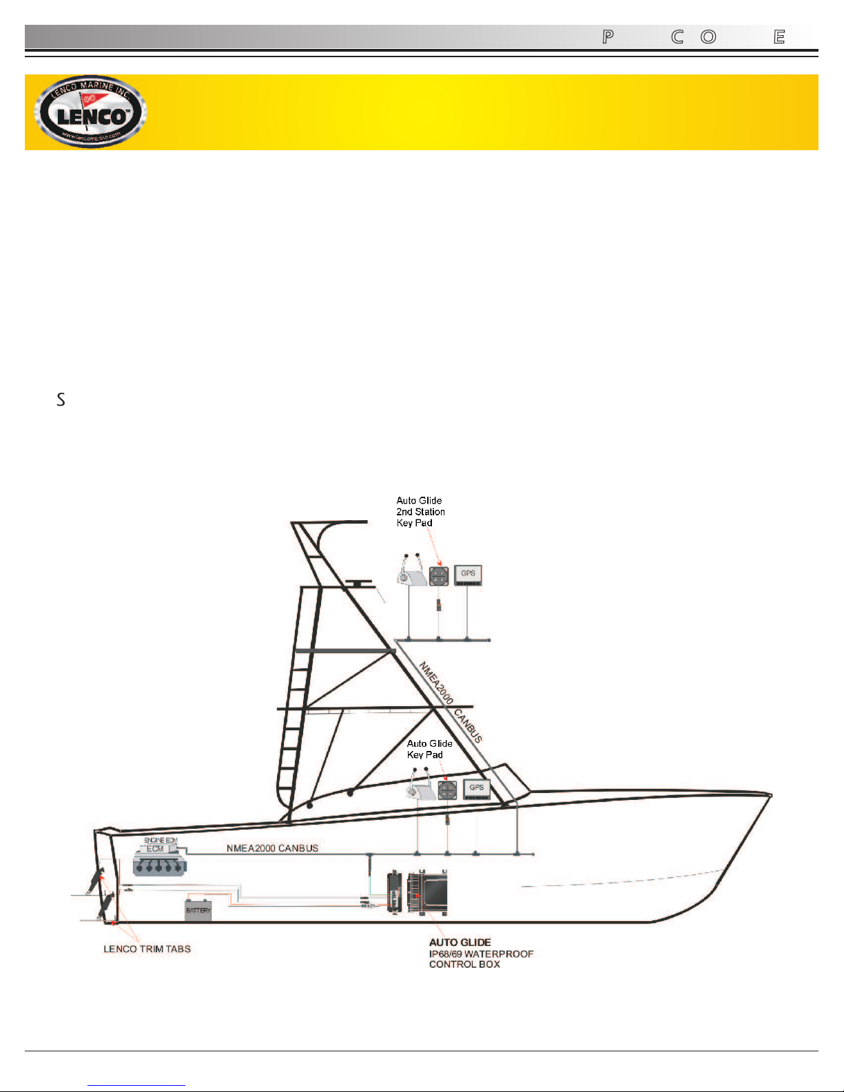
CONGRATULATIONS! You have just purchased the most advanced automatic trim tab
control system. Welcome to the future!
The Auto Glide Boat Control System is the first genuine fully automatic trim tab control
system in the world. The Auto Glide System uses unsurpassed technology to monitor the
boats speed and position, and automatically adjusts the trim tabs position to
accommodate any boating condition to provide a smoother, more comfortable ride. This
allows that boat operator to run the boat the way it was designed to perform.
¦ Fuel savings! GPH savings are recognized due to the boat running at it's most efficient
planing angle.
¦ Safety - better visibility due to improved hole shot mode and running angle and safer
due to the fact that you can focus your attention on boating matters other than the
trim tabs.
1.0 PRODUCT OVERVIEW
3
AUTO GLIDE
TM
Auto Glide System Product Overview
Rev 03-10-11
Page 4
1.0 PRODUCT OVERVIEW
4
AUTO GLIDE
NMEA2000 Engines J1939 Engines
¦ Yamaha ¦ Volvo Penta
(Non-EVC Engines)
(Command Link Plus requires NMEA 2000
¦ Yanmar
Yamaha Gateway P/N:6Y98A2D00000)
¦ Caterpillar
¦ Evinrude
¦ Cummins
¦ Honda
¦ Detroit Diesel
¦ Suzuki
¦ John Deere
¦ Volvo Penta (EVC Engines)
¦ Steyr
(With a Volvo NMEA2000 Gateway - Volvo P/N
3889757)
SmartCraft Engines
¦ Mercury - Verado
¦ Mercury - Optimax with SmartCraft ECU
¦ Mercruiser with SmartCraft ECU
¦ Cummins/Mercruiser w/ SmartCraft ECU
Available for these CANBUS-based engines:
¦ Boat must have CANbus based engine(s) (see list below)
¦ Boat must have NMEA 2000 GPS network or NMEA 2000 antenna receiver. NMEA
0183 will work, but will have slower signal response. Lenco offers a NMEA 2000 GPS
antenna receiver and optional stainless steel mounting bracket.
¦ Boat must have Lenco Single or Dual Trim Tab System with Lenco Electric Actuators
1.1 System Requirements
CAUTION
CAUTION
IMPORTANT INSTRUCTIONS AND FACTS ABOUT YOUR NEW AUTO GLIDE
BOAT CONTROL SYSTEM
** PLEASE READ ALL OF THE INSTALLATION INSTRUCTIONS IN THIS MANUAL BEFORE
PROCEEDING. YOU WILL NEED TO PRINT OUT YOUR APPLICABLE WIRING
SCHEMATIC / DRAWING / PARTS LIST FROM OUR WEBSITE BEFORE YOU BEGIN THE
INSTALLATION PROCESS.
** YOU MUST PERFORM ALL OF THE SET UP FUNCTIONS AFTER THE PROPER
INSTALLATION OF BUT BEFORE USING YOUR AUTO GLIDE SYSTEM
** YOU ARE RESPONSIBLE FOR:
(A) DETERMINING THAT YOUR SYSTEM IS A CANBUS BASED SYSTEM
(B) CONNECTING OUR NMEA 2000 CABLE TO ENGINE(S) (YOU MAY HAVE TO
CONTACT THE ENGINE MANUFACTURER)
(C) CONNECTING OUR CAN 2 CABLE TO A GPS NETWORK (IF APPLICABLE) (YOU
MAY HAVE TO CONTACT THE GPS MANUFACTURER)
WARNING
!
Rev 03-10-11
Page 5
TM
2.1 Auto Glide Key Pad Installation
TM
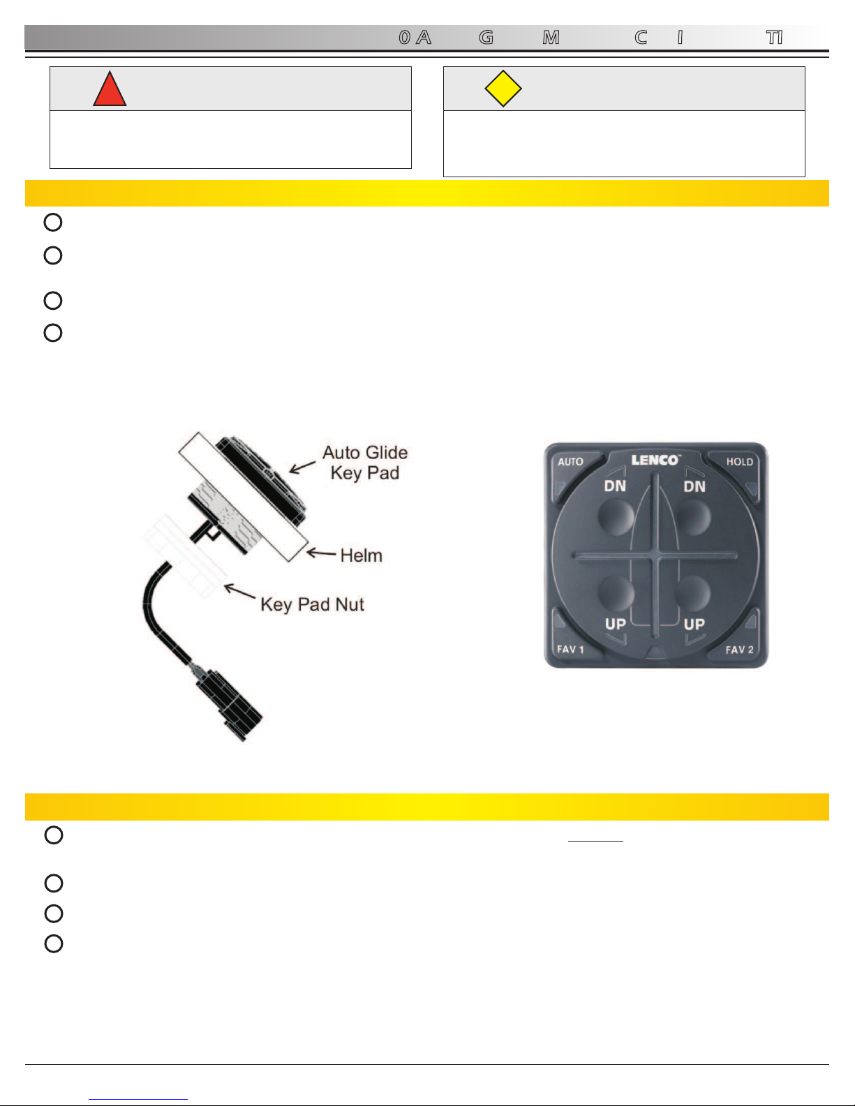
Determine where the Auto Glide key pad will be installed. Must have a 2.75” by 2.75” clearance on helm.
Before cutting, make sure the area inside the helm is clear of wires and other equipment that could be damaged. Find
center of key pad location and cut a circular opening using a 2” (5.08cm) hole saw (hole must be 2” (5.08cm)).
Drop key pad into 2” (5.08cm) hole.
From underneath the helm, hand tighten the large white key pad nut onto the back of the key pad. Make sure the key
pad is securely installed. (See Figure 2.1.1) Note: key pad nut can be flipped to accommodate helm thickness.
2.0 AUTO GLIDE MECHANICAL INSTALLATION
5
AUTO GLIDE
1
2.2 Replacing Existing 123 LED Indicator / 124 Standard Key Pad
From underneath the helm, disconnect the existing key pad from the control box. Squeeze the release mechanism on
the black wire and pull it away from the existing key pad.
Unscrew the four nylon nuts from the existing key pad posts.
From the top side of the helm, remove existing key pad.
TM
Install the Auto Glide key pad by simply dropping it into the existing 2” (5.08cm) hole and screw the large white key
pad nut onto the back of the key pad. Make sure the key pad is securely installed.
WARNING
!
Before cutting, make sure the inside the area inside the
helm is clear of wires and other equipment that could
be damaged.
CAUTION
Please read through the instructions in their entirety
prior to beginning installation! Proper function of this
product cannot be assured unless you follow these
instructions.
CAUTION
Figure 2.1.1 Figure 2.1.2
2
3
4
1
2
3
4
Rev 03-10-11
Page 6
2.0 AUTO GLIDE MECHANICAL INSTALLATION
6
TM
2.3 Auto Glide Control Box Installation
AUTO GLIDE
o
0
o
15
o
-15
BOW
STERN
o
0
o
15
o
-15
PORT STARBOARD
TM
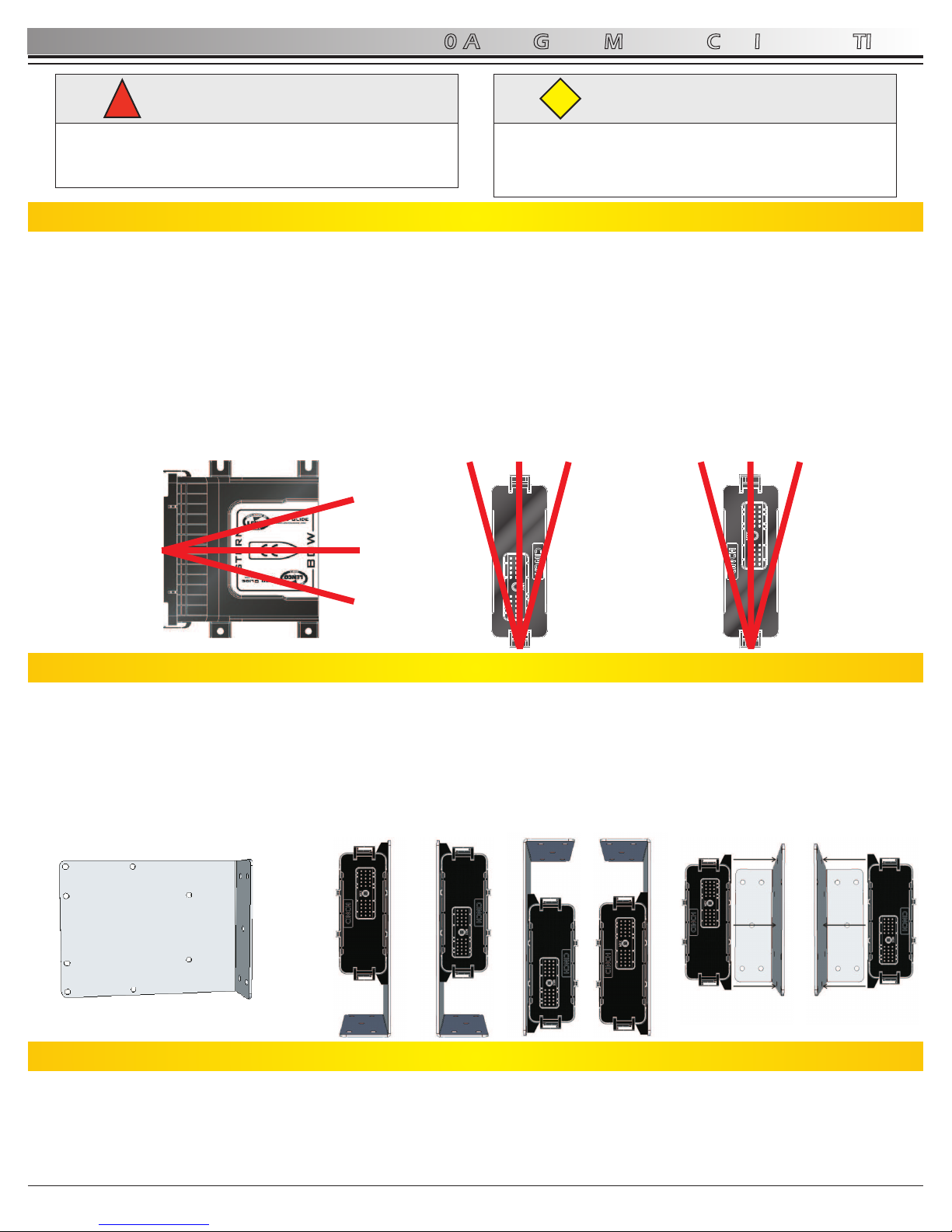
Determine where the Auto Glide control box will be installed.
- MUST BE INSTALLED ON A VERTICAL SURFACE WITH THE CONNECTOR FACING STERN (REAR OF
THE BOAT)! The top of the control box (sticker side) can face either port (left) or starboard (right). If a port or
TM
starboard vertical surface is not accessible, an optional Auto Glide control box mounting bracket is available. (See
section 2.4 below.)
o
- Install level. A 15 (+/-) tolerance in all directions is allowed. (See Figure 2.3.1)
TM
- Install within 4’ (1.21m) of the Auto Glide Key Pad. (If key pad must be installed further than 4’ use a CANBUS
Extension Cable 30260-XXX Series. See price list for different lengths.)
- Control box mounting hardware to be supplied by customer.
NOTE: DO NOT CONNECT POWER TO AUTO GLIDE CONTROL BOX AT THIS TIME
WARNING
!
Before drilling, make sure the mounting hardware will
not damage any existing wiring, structures, or hoses.
DO NOT CONNECT TO POWER AT THIS TIME.
CAUTION
Please read through the instructions in their entirety
prior to beginning installation! Proper function of this
product cannot be assured unless you follow these
instructions.
CAUTION
Figure 2.3.1
TM
2.4 Optional Auto Glide Control Box Mounting Bracket Installation
TM
Determine where the optional Auto Glide control box mounting bracket (Part # 70568-001) will be installed.
- L SHAPE MUST BE INSTALLED FACING EITHER PORT (LEFT) OR STARBOARD (RIGHT)! THE CONTROL
BOX MUST BE MOUNTED WITH THE CONNECTOR FACING STERN (REAR OF THE BOAT)! Top of the control
box (sticker side) can face either port or starboard. (See Figure 2.4.2 for some installation examples)
o
- Install level with the boat. A 15 (+/-) tolerance in all directions is allowed. (See Figure 2.3.1)
TM
- Install within 4’ (1.21m) of the Auto Glide key pad.
- Mounting bracket & control box mounting hardware included.
o
0
o
15
o
-15
PORT STARBOARD
To remove existing control box:
- Disconnect control box from power.
- Disconnect control box from actuators.
- Disconnect control box orange wire from tach or mechanical on / off switch.
- Remove two mounting screws and remove box from boat.
- See section 2.3 above for Auto Glide Control Box installation instructions.
2.5 Replacing Existing 123 / 123DR LED Indicator / 124 Standard Control Box
Figure 2.4.1 Figure 2.4.2
6”
8”
2”
Rev 03-10-11
Page 7
3.0 AUTO GLIDE ELECTRICAL INSTALLATION
7
TM
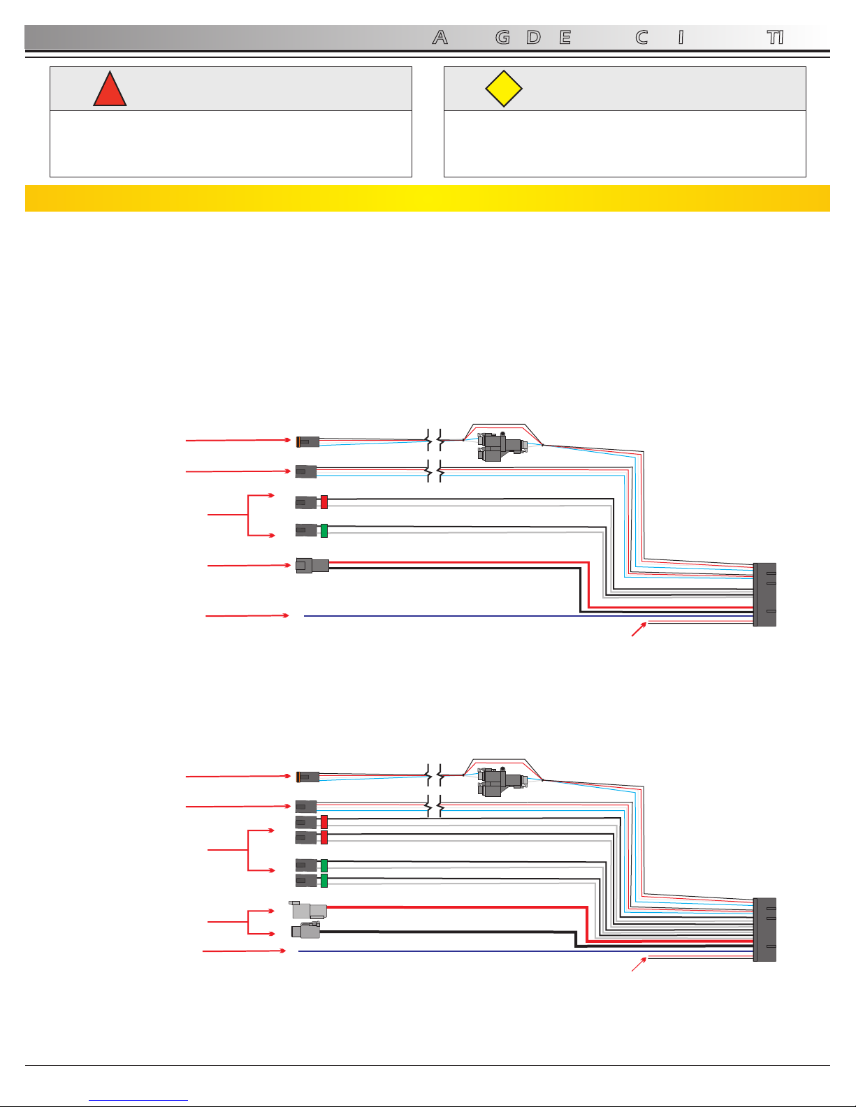
3.1 Auto Glide Control Box Harness Overview
AUTO GLIDE
TM
There are two types of Auto Glide Control Box Harnesses:
TM
- Single Actuator Auto Glide Control Box Harness for systems with two actuators (See Figure 3.1.1)
TM
- Dual Actuator Auto Glide Control Box Harness for systems with four actuators (See Figure 3.1.2)
TM
Each Auto Glide Control Box Harness has 6 sets of electrical connections coming out of the 30 pin Cinch connector.
WARNING
!
The power connections should always be the last
connection made.
Power connections should only be made while the
battery switch in the OFF position.
CAUTION
Please read through the instructions in their entirety
prior to beginning installation! Proper function of this
product cannot be assured unless you follow these
instructions.
CAUTION
Single Actuator Control Box Harness
Dual Actuator Control Box Harness
NMEA
0183(+/-)
DUAL ACTUATOR
LEAD CONNECTIONS
POWER CABLES
IGNITION
SENSE WIRE
NMEA
0183(+/-)
CANBUS #1
(Engine Data / GPS Data Source)
CANBUS #2
(Key Pad / GPS Data Source)
SINGLE ACTUATOR
LEAD CONNECTIONS
POWER CABLES
IGNITION
SENSE WIRE
1
2
DTP
Figure 3.1.1
Figure 3.1.2
CANBUS #1
(Engine Data / GPS Data Source)
CANBUS #2
(Key Pad / GPS Data Source)
Rev 03-10-11
Page 8

S
a
mpl
e
8
3.0 AUTO GLIDE ELECTRICAL INSTALLATION
AUTO GLIDE
TM
3.2 Auto Glide Control Box Harness Installation
DOWNLOAD YOUR REQUIRED DRAWING FROM THE WEBSITE: WWW.LENCOAUTOGLIDE.COM
- See sample drawing below
Connect the large black plug on the Auto Glide Control Box Harness into the Auto Glide Control Box.
- Make sure to line up the grooves.
Screw in the brass hex bolt on the plug into the control box with a 1/4” socket or 1/4” nut driver.
Connect the actuator lead connections on the control box harness and plug them into the actuator leads or actuator
extension harnesses.
- Make sure to connect the wire(s) with the red to the port (left) actuator(s) and the wire(s) with the green to
the starboard (right) actuator(s).
- See your Trim Tab Owner’s Manual for detailed instructions on Trim Tab installation and actuator hook up.
WARNING
!
CAUTION
CAUTION
1
2
3
4
Rev 03-10-11
As per your specific drawing (downloaded / printed from website) connect CAN #1 cable to Engine (for engine data) as
shown.
- If the Mercury or Yamaha hub is full, you will need to add an additional hub and jumpers.
As per your specific drawing (downloaded / printed from website) connect CAN #2 (Key Pad and GPS Data) as shown.
If your Lenco Trim Tab system is OEM - wired with a power harness, simply connect to the wires as shown in your drawing.
If you must run power to the system, you should purchase a power pigtail to plug into the Auto Glide main harness and
complete the wiring installation. Lenco also recommends the installation of a battery switch in the system. (See Page 9)
- NOTE: Lenco does not recommend the removal of our Deutsch connectors and replacing with hard wiring / butt splicing
to connect power to system.
Power Pigtail Choices: (May be purchased at all marine dealers and marine retail outlets)
Single Actuator Systems - Part # 30140-001 36” Power Pigtail or Part # 30140-202 72” Power Pigtail
Dual Actuator Systems - Part # 10249-001 72” Power Pigtail
30140-001 36” Power Pigtail
30140-202 72” Power Pigtail
10249-001 72” Power Pigtail
5
6
7
The power connections should always be the last
connection made.
Power connections should only be made while the
battery switch in the OFF position.
Please read through the instructions in their entirety
prior to beginning installation! Proper function of this
product cannot be assured unless you follow these
instructions.
Page 9

3.0 AUTO GLIDE ELECTRICAL INSTALLATION
9
AUTO GLIDE
3.3 Battery Switch Requirements
Lenco Marine recommends that the Auto Glide's main power input be connected to a battery switch to prevent unnecessary
drain on your battery while the Auto Glide is in STANDBY MODE. The Auto Glide Control Box and Key Pad draw a very small
amount of power (35mA) when it is in STANDBY MODE, but this small current draw will still drain your battery over time. In
addition, if the Auto Glide is powering a GPS antenna on CAN 2 (Key Pad Leads), then the amp draw increases and your
battery will drain even quicker.
Disconnecting power to the Auto Glide through a battery switch when your boat is not being used will eliminate any current
draw from your battery. The following illustrations outline how Lenco Marine recommends you connect the Auto Glide to a
battery switch.
3.4 Optional GPS (Stand Alone) Antenna Installation
The GPS module can be installed on any flat surface as long as there is room behind the mounting surface for the screws.
See Figures 3.4.1-3.4.2 on page 10 for more information. The optional Lenco Marine 70567-001 GPS Antenna/Receiver
Mounting Bracket kit (See Section 3.5 on page 11) allows you to install the antenna on any vertical surface.
Rev 03-10-11
The LGC -4000 (NMEA 2000) Antenna/Receiver consists of a male threaded cable connector and the GPS Module. The GPS
Module contains a 16-parallel channel GPS+WAAS receiver. The cable length from the connector to the GPS module is 18
inches (45.7 cm).
STANDARD LENCO
SINGLE ACTUATOR TRIM TAB INSTALLATION
AUTO GLIDE
CONTROL BOX
LENCO P/N
30255-001
NMEA0183 INPUTS
0183-
0183+
AUTO GLIDE
CONTROL BOX HARNESS
SINGLE ACTUATOR/TAB:
LENCO P/N: 30248-001
(4 FT)
IGNITION INPUT
I
N
P
U
T
O
U
T
P
U
T
1
2
DTP
BATTERY
1
2
DTP
DTP POWER
HARNESS
LENCO P/N:
30140-00X
(3 FT / 6 FT)
TRIM TAB ACTUATOR
CONNECTIONS
BATTERY
20AMP
FUSE/
BREAKER
MAIN POWER MUST
BE CONNECTED
TO BATTERY SWITCH
OR PROPERLY RATED
ON/OFF SWITCH
NOTE: TURN BATTERY SWITCH “OFF”
WHEN BOAT IS NOT BEING USED TO
ELIMINATE DRAIN ON BATTERY.
AUTO GLIDE
CONTROL BOX
LENCO P/N
30256-001
NMEA0183 INPUTS
STANDARD LENCO DUAL ACTUATOR TRIM TAB INSTALLATION
0183-
0183+
AUTO GLIDE
CONTROL BOX HARNESS
DUAL ACTUATOR/TAB:
LENCO P/N: 30247-001
(4 FT)
IGNITION INPUT
I
N
P
U
T
O
U
T
P
U
T
BATTERY
HD POWER
HARNESS
LENCO P/N:
10249-001
(6 FT)
TRIM TAB ACTUATOR
CONNECTIONS
BATTERY
MAIN POWER MUST
BE CONNECTED
TO BATTERY SWITCH
OR PROPERLY RATED
ON/OFF SWITCH
NOTE: TURN BATTERY SWITCH “OFF”
WHEN BOAT IS NOT BEING USED TO
ELIMINATE DRAIN ON BATTERY.
30AMP
FUSE/
BREAKER
BOAT
VOLTAGE LEVEL
12 VOLT 20 AMP
24 VOLT 10 AMP
CIRCUIT
PROTEC TION RATING
SINGLE ACTUATOR SYSTEMS
BOAT
VOLTAGE LEVEL
12 VOLT 30 AMP
24 VOLT 20 AMP
CIRCUIT
PROTECTION RATING
DUAL ACTUATOR SYSTEMS
Page 10

3.0 AUTO GLIDE ELECTRICAL INSTALLATION
10
AUTO GLIDE
Rev 03-10-11
3.4 GPS (Stand Alone) Antenna Installation (Continued)
Figure 3.4.1 Surface Mounting the GPS Antenna with No Obstructions Above the GPS Module
The GPS module can be installed on any flat surface that is at least 3-1/2” (90mm) wide. If you are mounting
the antenna on an external surface, Lenco Marine recommends that the antenna have a clear, unobstructed
view of the sky.
CLEAR, UNOBSTRUCTED
VIEW OF THE SKY
GPS ANTENNA/
RECEIVER
NO METAL (ONLY FIBERGLASS)
OBSTRUCTING THE VIEW OF THE SKY
GPS ANTENNA/
RECEIVER
Figure 3.4.2 Mounting the GPS Antenna With ONLY FIBERGLASS Obstructing The View of the Sky
If you cannot mount the GPS antenna to a flat surface with an unobstructed view of the sky, the Lowrance LGC4000 can be mounted under a fiberglass ceiling. However, you must make sure that there are no metal pipes or
plates which obstruct the view of the sky. The Lowrance GPS module can receive GPS Satellite signals through
two layers of fiberglass, but will not function properly if metal objects are in between the GPS module and the
view of the sky.
Here is an example of mounting the Lowrance LGC-4000 GPS Antenna to a flat surface under a fiberglass hard
top. The ceiling directly above the GPS antenna can only be fiberglass. If any of the aluminum bars supporting
the fiberglass hard top are directly over the antenna, the GPS module will not be able to receive clear satellite
signals.
Here is an example of mounting the Lowrance LGC-4000 GPS Antenna to a flat surface under two (2) layers of
fiberglass (Layer 1 = console, Layer 2 = hard top). Both ceilings directly above the GPS antenna can only be
fiberglass. If any of the aluminum bars supporting the fiberglass hard top are directly over the antenna, the GPS
module will not be able to receive clear satellite signals.
NO METAL (TWO LAYERS OF FIBERGLASS)
OBSTRUCTING THE VIEW OF THE SKY
GPS ANTENNA/
RECEIVER
Note: If you install the GPS Antenna/Receiver under a fiberglass ceiling, Lenco Marine recommends that you
verify that the Auto Glide is receiving GPS data from the GPS antenna before you physically attach the antenna
to the boat. Please review section 4.3 of this manual to learn how to verify that the Auto Glide is receiving GPS
data from the GPS antenna.
Page 11

3.0 AUTO GLIDE ELECTRICAL INSTALLATION
TM
3.6 Auto Glide Second Station Kit Installation
Lenco Marine offers 2nd Station Auto Glide kits ranging in lengths of 10' to 50'. These kits allow you to add a 2nd Key Pad to
your Auto Glide system and control the tabs automatically or manually from either station. Each Dual Station Kit includes a
2nd Station Key Pad, CANBUS Splitter Connector Hub and extension harness ranging from 10' to 50'.
Any 2nd Station Auto Glide kit can be used on either a Single or a Dual Actuator Trim Tab System. The following illustration
outlines how to connect an Auto Glide 2nd Station Kit:
11
TM
3.5 Optional Auto Glide GPS Mounting Bracket
If you do not have a flat surface to mount the GPS antenna, you can use the Lenco 70567-001 GPS Mounting Bracket Kit to
mount the Lowrance LGC-4000 GPS Antenna to a vertical surface. You still to need to make sure the antenna module has a
clear view of the sky or only has fiberglass above it.
Attach the GPS module to the mounting bracket using the two (2) #6-32 stainless steel bolts and nylon nuts that are included
in the mounting bracket kit. (See Figure 3.5.1)
Then attach the mounting bracket to a vertical surface using the four (4) ½” screws that are included in the mounting kit. (See
Figure 3.5.2)
Figure 3.5.1 Figure 3.5.2
ATTACH THE GPS MODULE TO THE MOUNTING BRACKET
USING THE TWO (2) #6-32 SS BOLTS AN THE NYLON NUTS
ATTACH THE MOUNTING BRACKET TO THE VERTICAL
SURFACE USING THE FOUR (4) ½”SS SCREWS INCLUDED
WITH THE MOUNTING BRACKET KIT.
2ND STATION KEY
PAD INCLUDED IN
2ND STATION KIT.
CANBUS SPLITTER
INCLUDED IN
2ND STATION KIT
SELECT 2ND STATION KIT
BASED ON LENGTH OF
EXTENSION HARNESS
BETWEEN 1ST AND 2ND
STATIONS (10 FT - 50 FT)
SEE PRICE LIST FOR
DIFFERENT KITS AVAILABLE.
1
2
DTP
AUTO GLIDE
CONTROL BOX
Sample
2ND STATION INSTALLATION EXAMPLE
NOTE: 2ND STATION
KEY PAD IS DIFFERENT
FROM MAIN KEY PAD
MAIN KEY PAD
AUTO GLIDE
Rev 03-10-11
Page 12

Putting the Auto Glide System into Test Mode
Identify Standby Mode: When battery power is applied to the control box, but the engine is OFF (not running), the Auto
Glide defaults to STANDBY MODE. During standby mode, the key pad LEDs are not illuminated. No single button will
function if pressed while Auto Glide is in standby mode. (See Figure 4.1.1)
Activate Test Mode: You must activate TEST MODE from STANDBY MODE to verify:
- That the trim tab actuators are operating properly without the engine running.
- The engine CANBUS data and GPS data is being received by the Auto Glide.
- To set/reset Home Roll and Pitch.
To activate TEST MODE, hold all four UP/DN buttons at the same time for four seconds. The UP/DN LED indicators
will illuminate when all four UP/DN buttons are pressed at the same time. (See Figure 4.1.2)
Verify Test Mode Activation: Once TEST MODE is activated, the LEDs on the key pad run through a sequence of
flashes to notify the operator that the Auto Glide is in TEST MODE. (Figures 4.1.3 and 4.1.4 outline this sequence.)
4.0 AUTO GLIDE INSTALLATION VERIFICATION
TM
4.1 Auto Glide Test Mode
Now that the Auto Glide has been installed and the engine and GPS data sources are connected, Lenco recommends that
you verify that the trim tab actuators are operating properly and that the Auto Glide is receiving the CANBUS engine and GPS
data it needs to make automatic leveling decisions.
12
AUTO GLIDE
1
2
3
Figure 4.1.1 Figure 4.1.2
Figure 4.1.3 Figure 4.1.4
DN
DN
A
U
T
O
UP
UP
F
H
F
A
O
A
V
L
V
1
D
2
TM
AFTER THE BRIEF SEQUENCE
OF LED FLASHES, THE LEDS OF THE
OUTSIDE FOUR AUTO SETTINGS
WILL REMAIN ILLUMINATED WHEN
THE AUTO GLIDE IS IN TEST MODE.
DN
DN
A
U
T
O
UP UP
F
H
F
A
O
A
V
L
V
1
D
2
TM
IMMEDIATELY FOLLOWING THE
FOUR (4) SECONDS OF HOLDING
THE UP/DN BUTTONS, THE FOUR
AUTOMATIC SETTING LEDS WILL
ILLUMINATE.
THE CROSSHAIR LEDS WILL
ALSO CONVERGE TO THE CENTER
AND THEN TURN OFF .
From TEST MODE, you can test the functionality of the trim tabs WITHOUT THE ENGINE RUNNING by pressing any of the
UP/DN buttons on the key pad (See Figure 4.2.1). This is an important step to perform after installing the Auto Glide because
it verifies that battery power and the port and starboard trim tabs are connected correctly.
NOTE: Port side UP/DN buttons should operate the Starboard trim tab actuator(s). Starboard side UP/DN buttons should
operate the Port trim tab actuator(s).
4.2 Testing The Trim Tab Actuators
Figure 4.2.1
DN
DN
A
U
T
O
UP UP
F
H
F
A
O
A
V
L
V
1
D
2
TM
From TEST MODE the operator or
installer can press any of the of the
UP/DN buttons to manually operate
the trim tab actuators.
Note: Port side UP/DN buttons should
operate the Starboard trim tab actuator(s).
Starboard side UP/DN buttons should
operate the Port trim tab actuator(s)
DN
DN
A
U
T
O
F
H
F
A
O
A
V
L
V
1
D
2
TM
WHILE ACTIVATING TEST MODE,
THE UP/DN LED INDICATORS WILL
ILLUMINATE WHEN ALL FOUR (4)
UP/DN BUTTONS ARE PRESSED
AT THE SAME TIME.
TO ACTIVATE TEST MODE,
HOLD ALL FOUR (4) UP/DN
BUTTONS AT THE SAME TIME
FOR FOUR (4) SECONDS.
DURING STANDBY MODE,
THE KEY PAD LEDS ARE NOT
ILLUMINATED.
NO SINGLE BUTTON WILL
FUNCTION IF PRESSED WHILE
AUTO GLIDE IS IN STANDBY
MODE.
DN
DN
A
U
T
O
UP
UP
F
H
F
A
O
A
V
L
V
1
D
2
TM
Rev 03-10-11
UP UP
UP UP
UP UP
UP
UP
Page 13

Verifying Auto Glide is Receiving GPS Data
If your Auto Glide system is receiving GPS Data you should see the following on your key pad:
Upper Quadrant = GPS Heading: Scrolling LEDs between green center crosshair and “12 O'clock”. (See Figure 4.3.2)
NOTE: GPS heading may only transmit when the boat is moving.
Right Quadrant = GPS Speed: Scrolling LEDs between green center crosshair and “3 O'clock”. (See Figure 4.3.2)
NOTE: GPS speed is always broadcast by GPS. Auto Glide must verify that GPS speed is available before the system can
operate properly.
4.0 AUTO GLIDE INSTALLATION VERIFICATION
4.3 CANBUS Data Verification
While the Auto Glide is in TEST MODE, you can activate DATA VERIFICATION MODE to confirm that the Auto Glide is
receiving the required Engine and GPS data, by pressing FAV 1 or FAV 2 (See Figure 4.3.1). This is a very important step to
perform because the Auto Glide cannot make automatic leveling decisions without specific Engine and GPS data.
13
AUTO GLIDE
Verifying Auto Glide is Receiving Engine Data
If your Auto Glide system is receiving Engine Data you should see the following on your key pad:
Left Quadrant = Engine Gear Position (forward or reverse): Scrolling LEDs between green center crosshair and “9 O'clock”.
(See Figure 4.3.3)
NOTE: Engine shift / gear position must be either SmartCraft DTS or NMEA 2000 shift data. Fwd or rev shift / gear position
may not be broadcast over the CANBUS if the engine is “off”.
NOTE: Engine shift / gear position is not required for the Auto Glide to operate normally. Heading, GPS Speed and Engine
Speed / RPM are required for the system to operate normally. If engine shift / gear position informantion is available, the
Auto Glide will retract the trim tabs when the engine is in reverse.
Lower Quadrant = Engine Speed / RPM: Scrolling LEDs between green center crosshair and “6 O'clock”. (See Figure 4.3.3)
NOTE: Engine speed is always broadcast when the engine ECU is active. Ignition key may have to be in the accessory
position for the ECU to become active.
DN
DN
A
U
T
O
UP
UP
F
H
F
A
O
A
V
L
V
1
D
2
TM
UPPER QUADRANT = GPS HEADING
SCROLLING LEDS BETWEEN GREEN
CENTER CROSSHAIR AND “12 O’CLOCK”.
NOTE: GPS HEADING MAY ONLY TRANSMIT
WHEN THE BOAT IS MOVED.
RIGHT QUADRANT = GPS SPEED
SCROLLING LEDS BETWEEN GREEN
CENTER CROSSHAIR AND “3 O’CLOCK”.
NOTE: GPS SPEED IS ALWAYS BROADCAST
BY GPS. AUTO GLIDE MUST VERIFY THAT
GPS SPEED IS AVAILABLE BEFORE THE
SYSTEM CAN OPERATE PROPERLY
Figure 4.3.2
Figure 4.3.3
DN
DN
A
U
T
O
UP
UP
F
H
F
A
O
A
V
L
V
1
D
2
TM
LEFT QUADRANT = ENGINE GEAR POSITION
(FORWARD OR REVERSE)
SCROLLING LEDS BETWEEN GREEN
CENTER CROSSHAIR AND “9 O’CLOCK”.
NOTE: ENGINE SHIFT POSITION MUST BE EITHER
SMARTCRAFT DTS OR NMEA 2000 SHIFT DATA.
FWD OR REV SHIFT POSITION MAY NOT BE
BROADCAST OVER THE CANBUS IF THE ENGINE
IS IN THE “OFF”.
LOWER QUADRANT = ENGINE SPEED (RPM)
SCROLLING LEDS BETWEEN GREEN
CENTER CROSSHAIR AND “6 O’CLOCK”.
NOTE: ENGINE SPEED IS ALWAYS BROADCAST
WHEN ENGINE ECU IS ACTIVE. IGNITION KEY
MAY HAVE TO BE IN THE ACCESSORY POSITION
FOR THE ECU TO BECOME ACTIVE.
Figure 4.3.1
DN
DN
A
U
T
O
UP UP
F
H
F
A
O
A
V
L
V
1
D
2
TM
From TEST MODE the operator or
installer can press either FAV 1 or
FAV 2 to initiate DATA VERIFICATION
MODE.
Rev 03-10-11
Page 14

Exit Data Verification Mode
Exit Test Mode
Press either FAV 1 or FAV 2 to exit out of DATA VERIFICATION MODE. (See Figure 4.4.1)
NOTE: Once you exit DATA VERIFICATION MODE, the Auto Glide reverts back to TEST MODE.
You should exit TEST MODE and go back into STANDBY MODE before starting the boat’s engine. Press and release all four
UP/DN buttons for 1 second to exit TEST MODE and the Auto Glide automatically reverts back into STANDBY MODE. (See
Figure 4.4.2)
Once you exit TEST MODE, the Auto Glide key pad is non-functional in STANDBY MODE. The Auto Glide control box will not
activate the key pad until the engine is started and the Auto Glide sees 400 RPM or greater over the CANBUS. Once the Auto
Glide sees that the boat's engine(s) are running at 400 RPM or greater, the Auto Glide will check to make sure it is receiving
the required GPS data, flash a series of LED indicators on the Key Pad and immediately default to HOME ROLL
CALIBRATION MODE.
4.0 AUTO GLIDE INSTALLATION VERIFICATION
4.4 Exiting Test Mode
14
AUTO GLIDE
Figure 4.4.1 Figure 4.4.2
DN
DN
A
U
T
O
UP
UP
F
H
F
A
O
A
V
L
V
1
D
2
TM
From DATA VERIFICATION MODE the
operator or installer can press either FAV 1
or FAV 2 to exit out of DATA VERIFICATION
MODE.
DN
DN
A
U
T
O
UP
UP
F
H
F
A
O
A
V
L
V
1
D
2
TM
TO EXIT TEST MODE, HOLD
ALL FOUR (4) UP/DN BUTTONS
AT THE SAME TIME FOR ONE
(1) SECOND.
Message if Auto Glide is NOT Receiving GPS or Engine Data
If your Auto Glide system is not receiving Engine or GPS Data you should see the following on your key pad:
Only the center crosshair will be illuminated green and the four outside lights will be illuminated red (indicating that you are
still in TEST MODE). (See Figure 4.3.4)
If none of the required Engine and GPS data is being received by the Auto Glide, Lenco recommends that you do the
following:
- Verify that the engine's ignition switch is placed in the “Accessory “ or “Run” position and the engine is transmitting data.
The engine instrumentation should be active if the engine is transmitting data.
- Verify that the GPS antenna is not obstructed from receiving satellite signals.
- If the GPS data is received from a NMEA 2000 Network, make sure the GPS is placed in the “ON” position.
- Make sure CAN #1 and CAN #2 data are properly connected to the Auto Glide.
DN
DN
A
U
T
O
UP
UP
F
H
F
A
O
A
V
L
V
1
D
2
TM
IF THE AUTO GLIDE IS NOT
RECEIVING ANY DATA FROM
EITHER THE ENGINE CANBUS
DATA SOURCE OR THE GPS
CANBUS DATA SOURCE,
ONLY THE CENTER CROSS
HAIR WILL BE ILLUMINATED
GREEN.
NOTE: THE OUTSIDE FOUR (4)
AUTO FEATURE BUTTONS
REMAIN ILLUMINATED TO
INDICATE THE AUTO GLIDE IS
STILL IN TEST MODE.
Figure 4.3.4
4.3 CANBUS Data Verification (Continued)
Rev 03-10-11
Page 15

HOME PITCH POSITION =
THE MOST EFFICIENT PLANING
ATTITUDE FOR YOUR BOAT
In order for the Auto Glide to automatically control the Roll and Pitch attitudes of a boat, the boat operator must
first set two default HOME POSITIONS:
1. HOME ROLL position (level side to side).
2. HOME PITCH position (most efficient running attitude bow to stern).
Please follow the setup instructions as carefully as possible to ensure you set the most accurate default HOME
positions as possible. However, if you make an error during set up, both HOME ROLL and HOME PITCH
positions can be erased and reset. Erasing and Resetting HOME ROLL and HOME PITCH will be described in
more detail in section 6.0 in this manual.
NOTE: Setting an accurate HOME ROLL position is very important to the performance of the Auto Glide. Lenco Marine
recommends setting the HOME ROLL DEFAULT position in smooth water conditions. If the boat is rocking back and forth
when the HOME ROLL DEFAULT position is calibrates, the HOME ROLL position may be slightly skewed to port or
starboard.
5.0 HOME ROLL AND PITCH SETUP INSTRUCTIONS
15
AUTO GLIDE
5.1 Home Roll and Pitch Overview
HOME ROLL POSITION =
BOAT IS LEVEL PORT TO STARBOARD
5.2 Home Roll Setup
INITIATE SETUP MODE: Once the Auto Glide installation has been completed and the operator or installer has verified
the trim tab actuators are connected properly and the required engine and GPS CANBUS data is being received, it is time
to set up HOME ROLL and HOME PITCH.
A. Verify that power from battery switch is in the “ON” position and the Auto Glide is in STANDBY MODE.
Figure 5.2.1
B. Turn your engine(s) “ON” so the Auto Glide sees 400 RPM or greater tach signal from the engine CANBUS.
1
DURING STANDBY MODE,
THE KEY PAD LEDS ARE NOT
ILLUMINATED.
NO SINGLE BUTTON WILL
FUNCTION IF PRESSED WHILE
AUTO GLIDE IS IN STANDBY
MODE.
DN
DN
A
U
T
O
UP UP
F
H
F
A
O
A
V
L
V
1
D
2
TM
Rev 03-10-11
Page 16

5.0 HOME ROLL AND PITCH SETUP INSTRUCTIONS
16
AUTO GLIDE
5.2 Home Roll Setup (Continued)
DN
DN
A
U
T
O
UP
UP
F
H
F
A
O
A
V
L
V
1
D
2
TM
BOTH UP ACTUATOR LED
INDICATORS FLASH AS
THE AUTO GLIDE RETRACTS
THE TRIM TABS ACTUATORS
TO ENSURE THE TRIM TABS
ARE FULLY RETRACTED
BEFORE INITIATING ROLL
AND PITCH CALIBRATION
MODES.
DN
DN
A
U
T
O
UP UP
F
H
F
A
O
A
V
L
V
1
D
2
TM
HORIZONTAL CROSSHAIR
LEDS WILL SCROLL FROM
SIDE TO SIDE TO INDICATE
THE AUTO GLIDE IS IN HOME
ROLL CALIBRATION MODE.
AUTO LED INDICATOR WILL
ILLUMINATE TO INDICATE THE
AUTO GLIDE IS IN AUTO MODE.
DN
DN
AA
UU
TT
OO
UP UP
F
H
F
A
O
A
V
L
V
1
D
2
TM
ALL OUTSIDE AUTO LED
INDICATORS AND UP/DN
INDICATORS WILL FLASH
BRIEFLY.
THE CROSSHAIR LEDS
WILL BRIEFLY CONVERGE
TO THE CENTER.
ST
1 SET OF LED FLASHES
ND
2 SET OF LED FLASHES
RD
3 SET OF LED FLASHES
Once the Auto Glide sees that the boat's engine(s) are running at 400 RPM or greater, the Auto Glide will check to make
sure it is receiving the required GPS data, flash a series of LED indicators on the Key Pad and immediately default to
HOME ROLL CALIBRATION MODE.
NOTE: You can verify that the engine(s) are broadcasting 400 RPM or greater over the engine CANBUS by inspecting the
tachometer value on the boat's instrumentation. If the boat's instrumentation shows a tachometer value of 400 RPM or
greater, Auto Glide should also be receiving this data and should default to HOME ROLL CALIBRATION MODE.
Here are the sequences of LED flashes that occur as the engine(s) are turned “ON” and the Auto Glide initiates SETUP
MODE.
NOTE: If GPS data is not available at the time the engine(s) are started, the Auto Glide will not default to setup mode.
Without the required engine and GPS data, the Auto Glide can not initiate HOME ROLL or PITCH calibration modes.
NOTE: If the Auto Glide does not default to HOME ROLL CALIBRATION MODE when the engine(s) are started and the
LEDs on the key pad flash for more than 10 seconds, please refer to the ‘System Failure Warning Messages’ contained in
Owner’s Manual B on page 33.
SET HOME ROLL DEFAULT POSITION: Once the Auto Glide is in HOME ROLL CALIBRATION MODE, you can set the
HOME ROLL DEFAULT POSITION. The Auto Glide will use this HOME ROLL POSITION to level the boat automatically
from port to starboard, while on plane.
NOTE: Setting an accurate HOME ROLL position is very important to the performance of the Auto Glide. Lenco Marine
recommends setting the HOME ROLL DEFAULT position in smooth water conditions. If the boat is rocking back and forth
when the HOME ROLL DEFAULT position is calibrated, the HOME ROLL position may be slightly skewed to port or
starboard.
2
Rough
Water
Smooth
Water
Rev 03-10-11
Page 17

DN
DN
A
U
T
O
UP UP
F
H
F
A
O
A
V
L
V
1
D
2
TM
5.0 HOME ROLL AND PITCH SETUP INSTRUCTIONS
17
AUTO GLIDE
5.2 Home Roll Setup (Continued)
When you determine that the boat is level from side to side, press and release the “AUTO” button one time. The Auto Glide
will store the boat’s ROLL POSITION as the DEFAULT HOME ROLL position at the exact moment the Auto button is
pushed.
DN
DN
A
U
T
O
UP UP
F
H
F
A
O
A
V
L
V
1
D
2
TM
THE ROLL POSITION OF THE
BOAT WILL BE STORED AS THE
DEFAULT HOME ROLL POSITION
AT THE MOMENT THE AUTO
BUTTON IS PUSHED.
PRESS AND RELEASE THE
AUTO BUTTON WHILE THE
AUTO GLIDE IS IN HOME ROLL
CALIBRATION MODE.
As soon as you release the “AUTO” button on HOME ROLL CALIBRATION MODE, the horizontal crosshair LEDs will stop
scrolling and the vertical crosshair LEDs will begin to scroll up and down to indicate that the Auto Glide is in HOME PITCH
CALIBRATION MODE.
DN
DN
A
U
T
O
UP UP
F
H
F
A
O
A
V
L
V
1
D
2
TM
THE VERTICAL LEDS ON THE
CROSSHAIR SCROLL UP AND
DOWN TO INDICATE THE AUTO
GLIDE IS IN HOME PITCH
CALIBRATION MODE.
NOTE: DO NOT TOUCH ANY OF THE FOUR (4) UP/DN BUTTONS ON THE KEY PAD WHILE THE AUTO GLIDE IS IN
HOME PITCH CALIBRATION MODE. If you touch the UP/DN buttons before setting the HOME PITCH DEFAULT
POSITION, the Auto Glide will convert to LIMP HOME MODE (manual Trim Tab control only). Once the Auto Glide is in
LIMP HOME MODE, you will have to shut the boat engine(s) off and back on again before the Auto Glide will revert back to
HOME PITCH CALIBRATION MODE.
SET HOME PITCH DEFAULT POSITION:
NOTE: Water conditions should be calm as possible during HOME PITCH CALIBRATION
Get the boat on plane without using the trim tabs. The tabs will be fully retracted.
NOTE: DO NOT TOUCH ANY OF THE
UP/DN BUTTONS ON THE KEY PAD
WHILE IN HOME PITCH CALIBRATION MODE, GET THE BOAT
ON PLANE WITHOUT USING YOUR TRIM TABS.
Once the boat is on plane, ensure the engine(s) are trimmed to match running surface of the boat.
HOLE SHOT - ENGINE TRIM POSITION
TRIM MOTOR(S) UNDER THE BOAT
TO ASSIST WITH HOLE SHOT
ON PLANE - ENGINE TRIM POSITION
TRIM MOTOR(S) ANGLE SO BOW IS HIGHER THAN
NORMAL, BUT NOT PORPOISING (BOW HOPPING)
ENGINE TRIM
MATCHES BOAT
RUNNING SURFACE
ENGINE TRIMMED
UNDER BOAT TO
AIDE HOLE SHOT
5.3 Home Pitch Setup
1
Rev 03-10-11
2
Page 18

5.0 HOME ROLL AND PITCH SETUP INSTRUCTIONS
18
AUTO GLIDE
5.3 Home Pitch Setup (Continued)
Get the boat to a maintained cruising speed.
NOTE: See Figures 5.3.1 and 5.3.2 for recommended cruising speeds.
Figure 5.3.1: GAS ENGINE = 65% OF MAX RPM.
EXAMPLE: GASOLINE 4 STROKE OUTBOARD
MAX RPM = 6000 RPM
CRUISE @ 65% MAX RPM = 3900 RPM
MAX RPM = 6000 RPM
CRUISE RPM = 3900 RPM
(65% OF MAX)
0
1
2
3
4
5
6
7
8
4000 RPM
EXAMPLE: DIESEL INBOARD
MAX RPM = 3000 RPM
CRUISE @ 80% MAX RPM = 2400 RPM
MAX RPM = 3000 RPM
CRUISE RPM = 2400 RPM
(80% OF MAX)
0
1
2
3
4
2400 RPM
Figure 5.3.2: DIESEL ENGINE = 80% OF MAX RPM.
After getting the boat to cruising speed, press and release the Auto Button to initiate the HOME PITCH CALIBRATION
PROCESS.
DN
DN
A
U
T
O
UP UP
F
H
F
A
O
A
V
L
V
1
D
2
TM
THE VERTICAL CROSSHAIR
LEDS WILL SCROLL QUICKER
AFTER RELEASING THE
AUTO BUTTON TO INDICATE
THE HOME PITCH CALIBRATION
PROCESS HAS BEGUN.
PRESS AND RELEASE THE
AUTO BUTTON TO INITIATE
HOME PITCH CALIBRATION
MODE.
Setting the HOME PITCH DEFAULT POSITION takes 66 seconds from the moment you enter HOME PITCH
CALIBRATION PROCESS. You should drive the boat as straight as possible during the 66 seconds of the HOME PITCH
CALIBRATION PROCESS.
NOTE: Adjust people and load on the boat to keep roll as level as possible during the HOME PITCH CALIBRATION
PROCESS (Do not use tabs to level load).
HOME PITCH CALIBRATION PROCESS TAKES 66 SECONDS FROM
THE MOMENT THE AUTO BUTTON IS PUSHED UNTIL THE HOME
PITCH DEFAULT POSITION IS CALCULATED.
PRESS AUTO BUTTON
TO START HOME PITCH
CALIBRATION PROCESS
HOME PITCH DEFAULT
POSITION IS CALCULATED
AT THE END OF THE 66 SEC
CALIBRATION PROCESS
0
SECS
66
SECS
TAB ARE FULLY
RETRACTED AT
START OF CALIBRATION
PROCESS
TAB ARE FULLY
EXTENDED AT THE
END OF THE CALIBRATION
PROCESS
TABS ARE EXTENDED IN SHORT BURSTS EVERY 6
SECONDS THROUGHOUT THE CALIBRATION PROCESS
DRIVE BOAT AS STRAIGHT AS POSSIBLE
DURING PITCH CALIBRATION PROCESS
Rev 03-10-11
3
4
Page 19

5.0 HOME ROLL AND PITCH SETUP INSTRUCTIONS
19
AUTO GLIDE
5.3 Home Pitch Setup (Continued)
During the HOME PITCH CALIBRATION PROCESS, the key pad vertical scrolling crosshair LEDs will continue to scroll
quickly and the DN LEDs will flash every 6 seconds as the tabs are extended in short bursts.
DN
DN
A
U
T
O
UP UP
F
H
F
A
O
A
V
L
V
1
D
2
TM
THE VERTICAL CROSSHAIR
LEDS WILL CONTINUE TO SCROLL
QUICKLY THROUGHOUT THE HOME
PITCH CALIBRATION PROCESS.
THE DN LED INDICATORS WILL
FLASH EACH TIME THE ACTUATORS
ARE EXTENDED DURING THE HOME
PITCH CALIBRATION PROCESS.
Immediately after the HOME PITCH CALIBRATION PROCESS is complete, the scrolling light disappears, the Auto Glide
will calculate the optimum pitch angle for the boat, and will save it as the HOME PITCH DEFAULT POSITION.
The Auto Glide will then immediately default to AUTO MODE and begin leveling the boat based on these HOME
ROLL DEFAULT POSITION and the HOME PITCH DEFAULT POSITION.
HOME PITCH
DEFAUL
T
POSITION
TRIM TABS RETRACT IN
BRIEF BURSTS UNTIL
BOAT’S RUNNING ANGLE
REACHES HOME PITCH
DEFAULT POSITION.
NEG BOW ANGLE
TRIM TABS ARE FULLY
DEPLOYED IMMEDIATELY
AFTER COMPLETION OF
HOME PITCH CALIBRATION
PROCESS.
DN
DN
A
U
T
O
UP UP
F
H
F
A
O
A
V
L
V
1
D
2
TM
AS SOON AS THE HOME PITCH
DEFAULT POSITION IS SAVED, THE
VERTICAL LEDS ON THE CROSSHAIR
STOP SCROLLING
THE AUTO GLIDE WILL DEFAULT TO
AUTO MODE AND BEGIN TO RETRACT
THE TRIM TABS IN SHORT BURSTS BASED
ON THE ROLL AND PITCH POSITION OF
THE BOAT.
THE TABS WILL CONTINUE TO COME
UP UNTIL THE BOAT REACHES THE
HOME PITCH DEFAULT POSITION.
Rev 03-10-11
5
The setup process is now complete
Page 20

2
If you experience a problem during the HOME PITCH CALIBRATION PROCESS and feel the resulting HOME PITCH
DEFAULT POSITION is not accurate, you can erase the HOME PITCH DEFAULT POSITION from TEST MODE. You must
first erase the HOME PITCH DEFAULT POSITION before you can re-enter the HOME PITCH CALIBRATION PROCESS and
allow the AUTO GLIDE to learn a new HOME PITCH DEFAULT POSITION.
NOTE: HOME ROLL DEFAULT POSITION will not be affected when you erase the HOME PITCH DEFAULT POSITION.
Section 6.2 will explain how to erase the HOME ROLL DEFAULT POSITION.
The following illustrations outline how to erase the HOME PITCH DEFAULT POSITION from TEST MODE.
6.0 RESETTING HOME ROLL AND PITCH SETUP INSTRUCTIONS
20
AUTO GLIDE
6.1 Resetting Home Pitch Default Position ONLY
Rev 03-10-11
DN
DN
A
U
T
O
UP
UP
F
H
F
A
O
A
V
L
V
1
D
2
TM
WHILE ACTIVATING TEST MODE, THE UP/DN LED
INDICATORS WILL ILLUMINATE WHEN ALL FOUR (4)
UP/DN BUTTONS ARE PRESSED AT THE SAME TIME.
TO ACTIVATE TEST MODE,
HOLD ALL FOUR (4) UP/DN
BUTTONS AT THE SAME TIME
FOR FOUR (4) SECONDS.
1
ACTIVATE TEST MODE:
With your motor(s) turned “OFF”, activate TEST MODE from STANDBY MODE by pressing and holding
all four (4) UP/DN buttons on the Key Pad for four (4) seconds.
VERIFY TEST MODE ACTIVATION:
Once TEST MODE is activated, the LEDS on the key pad run through a sequence of flashes to notify the operator
that the Auto Glide is in TEST MODE. The following illustrations outline this sequence of LED flashes signifying the
Auto Glide is in TEST MODE:
DN
DN
A
U
T
O
UP UP
F
H
F
A
O
A
V
L
V
1
D
2
TM
AFTER THE BRIEF SEQUENCE
OF LED FLASHES, THE OUTSIDE
FOUR AUTOMATIC SETTINGS LED
INDICATORS WILL REMAIN
ILLUMINATED WHEN THE AUTO
GLIDE IS IN TEST MODE.
DN
DN
A
U
T
O
UP
UP
F
H
F
A
O
A
V
L
V
1
D
2
TM
IMMEDIATELY FOLLOWING THE
FOUR (4) SECONDS OF HOLDING
THE UP/DN BUTTONS, THE FOUR
AUTOMATIC SETTINGS LEDS WILL
ILLUMINATE.
THE CROSSHAIR LED INDICATORS
WILL ALSO CONVERGE TO THE
CENTER AND THEN GO BLANK .
3
ERASING HOME PITCH DEFAULT POSITION:
Once the Auto Glide is in TEST MODE, press and hold the “HOLD” AUTOMATIC SETTING button until the “HOLD”
LED INDICATOR flashes three times. The three flashes of the “HOLD” LED INDICATOR confirms that the HOME
PITCH DEFAULT POSITION has been erased.
DN
DN
A
U
T
O
UP
UP
F
H
F
A
O
A
V
L
V
1
D
2
TM
WHILE THE AUTO GLIDE IS
IN TEST MODE, PRESS AND
HOLD THE “HOLD” AUTOMATIC
SETTING BUTTON UNTIL THE
“HOLD” LED INDICATOR FLASHES
THREE (3) TIMES.
ONCE THE “HOLD” LED INDICATOR
STOPS FLASHING, THE HOME PITCH
DEFAULT POSITION HAS BEEN ERASED.
Page 21

6.0 RESETTING HOME ROLL AND PITCH SETUP INSTRUCTIONS
21
AUTO GLIDE
6.1 Resetting Home Pitch Default Position ONLY (Continued)
Rev 03-10-11
After erasing the HOME PITCH DEFAULT POSITION, you must exit TEST MODE before you can re-enter the HOME
PITCH CALIBRATION MODE. Exit TEST MODE by holding down all four (4) UP/DN buttons for one (1) second. The
AUTOMATIC SETTING LED INDICATORS will go blank indicating the Auto Glide is back in STANDBY MODE.
4
EXIT TEST MODE:
DN
DN
A
U
T
O
UP UP
F
H
F
A
O
A
V
L
V
1
D
2
TM
TO EXIT TEST MODE, HOLD
ALL FOUR (4) UP/DN BUTTONS
AT THE SAME TIME FOR ONE
(1) SECOND.
5
RESET HOME PITCH DEFAULT POSITION:
Restart your motor(s) and the Auto Glide will default to HOME PITCH CALIBRATION MODE. The VERTICAL
CROSSHAIR LED INDICATORS will scroll up and down to indicate the Auto Glide is ready to reset a new HOME
PITCH DEFAULT POSITION.
Return to page 17 of this manual for HOME PITCH SETUP INSTRUCTIONS and follow the instructions to set the
new HOME PITCH DEFAULT POSITION.
6.2 Resetting Home Roll and Home Pitch Default Positions
If you need to reset the HOME ROLL DEFAULT POSITION, you will also need to erase and reset the HOME PITCH
DEFAULT POSITION. The Auto Glide erases both HOME ROLL AND HOME PITCH DEFAULT POSITIONS when you erase
the HOME ROLL DEFAULT POSITION. Even if you only want to erase the HOME ROLL DEFAULT POSITION, the Auto Glide
will automatically erase the HOME PITCH DEFAULT POSITION.
The following instructions explain how to erase and reset both HOME ROLL AND HOME PITCH DEFAULT POSITIONS.
1
ACTIVATE and VERIFY TEST MODE:
SEE STEPS 1 & 2 ON PAGE 20
2
ERASING HOME ROLL AND PITCH DEFAULT POSITION:
Once the Auto Glide is in TEST MODE, press and hold the “AUTO” AUTOMATIC SETTING button until the “AUTO”
LED INDICATOR flashes three times. The three flashes of the “AUTO” LED INDICATOR confirm that both the HOME
ROLL AND PITCH DEFAULT POSITIONS have been erased.
DN
DN
A
U
T
O
UP UP
F
H
F
A
O
A
V
L
V
1
D
2
TM
WHILE THE AUTO GLIDE IS
IN TEST MODE, PRESS AND
HOLD THE “AUTO” AUTOMATIC
SETTING BUTTON UNTIL THE
“AUTO” LED INDICATOR FLASHES
THREE (3) TIMES.
ONCE THE “AUTO” LED INDICATOR
STOPS FLASHING, BOTH THE HOME
ROLL AND PITCH DEFAULT POSITIONS
HAVE BEEN ERASED.
DN
DN
A
U
T
O
UP UP
F
H
F
A
O
A
V
L
V
1
D
2
TM
AS SOON AS THE “AUTO” LED
INDICATOR STOPS FLASHING,
THE HORIZONTAL CROSS HAIR
LED INDICATORS SCROLL BACK
AND FORTH TO INDICATE THE
AUTO GLIDE HS RE-ENTERED
HOME ROLL CALIBRATION MODE.
ONCE THE AUTO GLIDE HAS ERASED
THE HOME ROLL DEFAULT POSITION,
YOU MUST RESET THE HOME ROLL
DEFAULT POSITION BEFORE EXITING
OUT OF TEST MODE.
NOTE: IF YOU DO NOT RESET THE HOME ROLL DEFAULT POSITION BEFORE EXITING TEST
MODE, THE AUTO GLIDE WILL AUTOMATICALLY RESAVE THE PREVIOUS HOME ROLL DEFAULT
POSITION WHEN YOU EXIT OUT OF TEST MODE.
Page 22

6.0 RESETTING HOME ROLL AND PITCH SETUP INSTRUCTIONS
22
AUTO GLIDE
6.2 Resetting Home Roll and Home Pitch Default Positions (Continued)
Rev 03-10-11
Once the Auto Glide is in ROLL CALIBRATION MODE, you will need to reset the HOME ROLL DEFAULT POSITION
by pressing and releasing the “AUTO” Automatic button.
RESET HOME ROLL DEFAULT POSITION:
CONFIRMATION NEW HOME ROLL DEFAULT POSITION HAS BEEN SAVED:
Once you release the “AUTO” AUTOMATIC SETTING button the “AUTO” LED INDICATOR will flash three times. The
three flashes of the “AUTO” LED INDICATOR confirm that the new HOME ROLL DEFAULT POSITIONS has been
stored. The HORIZONTAL CROSSHAIR LED INDICATORS will also stop scrolling to indicate the Auto Glide has
exited out of HOME ROLL CALIBRATION MODE and has defaulted back into TEST MODE.
3
4
NOTE: SETTING AN ACCURATE HOME ROLL DEFAULT POSITION IS VERY IMPORTANT TO THE
PERFORMANCE OF THE AUTO GLIDE. LENCO MARINE RECOMMENDS SETTING THE HOME ROLL DEFAULT
POSITION IN SMOOTH WATER CONDITIONS. IF THE BOAT IS ROCKING BACK AND FORTH WHEN THE HOME
ROLL DEFAULT POSITION IS CALIBRATED, THE HOME ROLL POSITION MAY BE SLIGHT SKEWED TO PORT
OR STARBOARD.
DN
DN
A
U
T
O
UP UP
F
H
F
A
O
A
V
L
V
1
D
2
TM
THE NEW ROLL POSITION OF THE
BOAT WILL BE STORED AS THE
HOME ROLL DEFAULT POSITION
AT THE MOMENT THE AUTO
BUTTON IS PUSHED.
PRESS AND RELEASE THE
“AUTO” AUTOMATIC SETTING
BUTTON WHILE THE AUTO
GLIDE IS IN HOME ROLL
CALIBRATION MODE.
DN
DN
A
U
T
O
UP UP
F
H
F
A
O
A
V
L
V
1
D
2
TM
AS SOON AS THE “AUTO” LED
INDICATOR STOPS FLASHING,
THE HORIZONTAL CROSSHAIR
LED INDICATORS ALSO STOP
SCROLLING TO INDICATE THE
AUTO GLIDE HAS SAVED THE NEW
HOME ROLL DEFAULT POSITION.
ONCE THE AUTO GLIDE HAS STORED
THE HOME ROLL DEFAULT POSITION,
IT DEFAULTS BACK TO TEST MODE.
After erasing the HOME PITCH DEFAULT POSITION, you must exit TEST MODE before you can re-enter the HOME
PITCH CALIBRATION MODE. Exit TEST MODE by holding down all four (4) UP/DN buttons for one (1) second. The
AUTOMATIC SETTING LED INDICATORS will go blank indicating the Auto Glide is back in STANDBY MODE.
SEE ILLUSTRATION ON PAGE 21.
5
EXIT TEST MODE:
6
RESET HOME PITCH DEFAULT POSITION:
Restart your motor(s) and the Auto Glide will default to HOME PITCH CALIBRATION MODE. The VERTICAL
CROSSHAIR LED INDICATORS will scroll up and down to indicate the Auto Glide is ready to reset a new HOME
PITCH DEFAULT POSITION.
Return to page 15 of the HOME ROLL AND PITCH SETUP INSTRUCTIONS and follow the instructions to set the
new HOME PITCH DEFAULT POSITION.
END OF OWNER’S MANUAL A
Refer to Owner’s Manual B for Operational Instructions
 Loading...