

Page 1
19
Owner’s Manual
Operation of
Trolling Motors
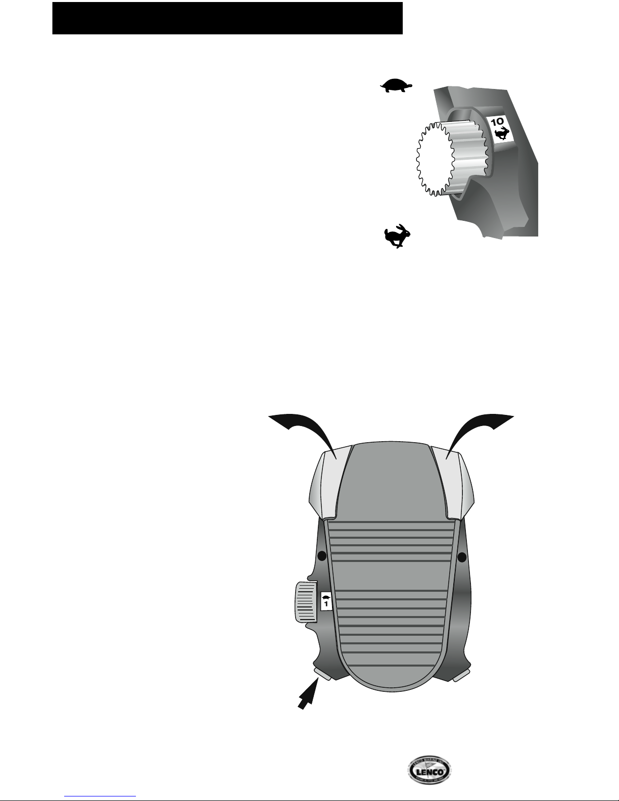
To position the motors for trolling
use, press BOW DOWN for more
than 5 seconds on the trim tab
switch or DOWN on the rocker
switch for Lenco Drives. This will fully
extend both actuators so the motors
are parallel with the plane of the hull.
To begin use with the trolling motors,
turn the control box ON by flipping
the single toggle switch. When the
system is activated, you may operate
the motors with the foot control
that plugs into the control box wire
harness.
Direction
The Troll’n Tab and Lenco Drive 164
trolling motor systems maneuver the
boat by controlling the direction and
the amount of thrust from each of
the trolling motors. Pressing down on
the heel of the foot control will steer
the boat to the left. When the heel is
pressed down, the starboard motor
thrusts forward and the port motor
thrusts in reverse. Pressing down
on the toe of the foot pedal steers
the boat to the right. When the toe
is pressed down, the port motor
thrusts forward and the starboard
motor thrusts in reverse. The amount
of thrust and the direction of thrust
gradually change from one motor
to the other the further the foot
control is pressed down. When the
foot control is pressed down all the
way to either the toe or heel, the
trolling motors are at equal thrust
levels, one motor pushing forward,
the other pushing in reverse. To track
in a straight line, the foot pedal has
a center position which is calibrated
to equal the amount of thrust and
the direction of each motor. This
“center” position may not equal a
perfectly level foot pedal. The pedal
may appear tilted while achieving a
straight tracking line.
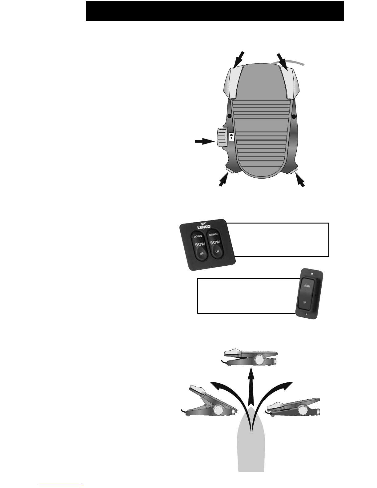
Foot Control Functions
Momentary
Buttons
Speed
Control
Knob
Forward
&
Reverse
Constant
&
Momentary
Turn Left
Heel Down
Turn Right
Toe Down
Straight
Center Foot Pedal
Press BOW DOWN for
more than 5 seconds
to position TNT trolling
motors for use.
Troll’n Tab & Lenco Drive 164 Motor Operation/Maneuvering
Press DOWN for more
than 5 seconds to
position Lenco Drive 164
trolling motors for use.
Page 2
20
Lenco Marine
Speed
The speed of the motor can be adjusted to the
desired speed by rolling the speed control knob on
the left side of the foot control. This is a variable
speed system so it offers a full range of thrust
levels. This range is marked 1 through 10. Position
1 is marked on the knob by a turtle for the lowest
thrust level. A rabbit for the highest thrust marks
position 10. Use your foot to roll the speed control
knob to the desired setting.
Momentary Mode
When the main control box is turned on, the foot
control begins in the momentary mode. Each time
one of the gray momentary buttons is pressed,
the motors activate; when released the motors
stop. When activated, the motors run at the speed
controlled by the setting of the speed control knob.
Constant Mode
To set the foot control to the constant mode, press
the small gray button on the left at the base of the
foot control one time. This mode allows the motors
to run constantly at the speed selected on the
speed control knob.
Constant
Mode Steering
Adjustments
When the foot control is
set in the constant mode,
it is possible to make small
directional adjustments.
To make each adjustment,
press the right or left gray
momentary buttons one
time. This allows, the boat
to track 5 percent in the
desired direction. If one of
the two momentary buttons
is pressed and held down, the
boat continues to go in that
direction until the button is
released or the opposite button
is pressed.
Speed Control
Knob
1
2
3
4
5
6
7
8
9
10
Momentary
Buttons
Set in Constant Mode
to use Momentary Buttons
for small adjustments
Press
one time
to track
right
5%
Press
one time
to track
left
5%
Troll’n Tab & Lenco Drive 164 Motor Maneuvering
Page 3

21
Owner’s Manual
Troll’n Motor Maneuvering
Forward and Reverse
When the main control box is turned on, the
foot control begins in forward. To set the
foot control to the reverse mode, press the
small gray button on the right at the base of
the foot control one time. This reverses all of
the functions described above. This setting
is most effective and used most often when
the foot control is set at the center position.
This function is helpful to back up out of tight
areas and maneuver away from obstructions.
On the Water
Lenco Marine would like your first experience
with your new Troll’n Tab or Lenco Drive
164 trolling motor system to be enjoyable.
Please take your time and walk through
the previously mentioned settings. You will
learn how to calibrate the motors in the
momentary, constant and straight ahead
positions to maximize the systems full
potential.
Special
Recommendations for
Troll’n Tabs &
Lenco Drive 164
Make sure that the control box
is switched to OFF after use.
Momentary
Buttons
Speed
Control
Knob
Forward
&
Reverse
Constant
&
Momentary
1 Stainless steel electro-polished blade with hinge #BTNT 9x12
(dimensions of tab)
2 Trolling motor bracket Bracket
3 Motorguide 24v-82lbs #MG24DV-82
4 Motorguide Machette II (3 blade prop) Prop
5 Anti-cavitation plate
6 #124 - Standard Tactile Switch (optional) #124
7 #123 TNT - Troll’n Tab L.E.D. Indicator
Switch w/Retractor (optional) #123 TNT
8 Electromechanical Actuator #102 XD
9 Upper mounting bracket #118
10 Lower mounting bracket #119
11 Delrin pin #121
12 Shim kit (optional) #118S
13 TNT control box with wire harness and terminal strip #TNTCB
14 TNT foot control #TNTFC
15 Nylon spacers
16 5/16" (.79 cm) Machine lock nut
17 5/16" x 2-1/4" (.79 x 5.72 cm) machine bolt
Troll’n Tab System Parts (See page 31 for Lenco Drive parts.)
Troll’n Tab & Lenco Drive 164 Motor Maneuvering, System Parts
 Loading...