

Page 1
00 NIM-CAMAC
& 01 COAXIAL
CONNECTORS
Page 2
Page 3
1www.lemo.com
®
®
LEMO coaxial 00 and 01 Series (50 Ω )
Table of Contents
Fundamental research in particle physics as practised within CERN and other nuclear research establishments requires
more and more complex equipment of high performance in order to achieve the objectives. The needs of such research
contribute to the development of leading products for the whole of industry. For many years LEMO has participated in
this evolution. This has resulted in a range of miniature coaxial connectors (50 Ω) with a push-pull self-latching system,
the LEMO 00.250 series. These connectors now form the basis of the NIM-CAMAC CD/N 549 standard.
The plugs and sockets of the 01 series are amongst the smallest available 50 Ω coaxial connectors with a self-latching
intermating capability. In spite of their small size and light weight, their technical characteristics remain excellent. Available in a wide range of housing configurations, they are especially useful when connecting onto printed circuit boards.
The LEMO 00 series and 01 are now used in many areas such as : telecommunications, sensors, medical equipment,
space research, etc...
The program covered in this catalog now includes more than 50 models suitable for many cable types.
2 steps to select the right connector ................................................................................................................................................................................3
00.250 (NIM-CAMAC CD/N 549) Series
Part numbering system ........................................................................................................................................................................................... 7
Metal housing models ............................................................................................................................................................................................. 8
Plastic housing models ......................................................................................................................................................................................... 21
Watertight or vacuumtight models ....................................................................................................................................................................... 22
Metal housing models with mechanical keying .................................................................................................................................................... 24
Threaded-latching models .................................................................................................................................................................................... 26
Adaptors ............................................................................................................................................................................................................... 27
Variant .................................................................................................................................................................................................................. 30
Assembled cables ................................................................................................................................................................................................ 31
Accessories .......................................................................................................................................................................................................... 31
Spare parts ........................................................................................................................................................................................................... 33
Tooling .................................................................................................................................................................................................................. 35
Panel cut-outs ...................................................................................................................................................................................................... 38
Cable assembly .................................................................................................................................................................................................... 39
01.250 (Minax) Series
Part numbering system ......................................................................................................................................................................................... 45
Metal housing models .......................................................................................................................................................................................... 46
Threaded-latching models ................................................................................................................................................................................... 50
Adaptors ............................................................................................................................................................................................................... 50
Spare parts ........................................................................................................................................................................................................... 51
Tooling .................................................................................................................................................................................................................. 52
Panel cut-outs ...................................................................................................................................................................................................... 53
Cable assembly .................................................................................................................................................................................................... 53
Technical characteristics
Outer shell ............................................................................................................................................................................................................. 55
Insulator ................................................................................................................................................................................................................ 56
Electrical contact .................................................................................................................................................................................................. 56
Cable fixing ........................................................................................................................................................................................................... 58
Technical tables (VSWR) ....................................................................................................................................................................................... 58
Product safety notice ........................................................................................................................................................................................... 59
Page 4
®
®
Precision modular connectors to suit your application
Since its creation in Switzerland in 1946 the LEMO Group has been recognized as a global leader of circular Push-Pull
connectors and connector solutions. Today LEMO and its affiliated companies, REDEL and COELVER, are active in
more than 80 countries with the help of over 40 subsidiaries and distributors.
Over 75’000 connectors
The modular design of the LEMO range provides over 75’000 connectors from miniature ø 3 mm to ø 50 mm, capable
of handling cable diameters up to 30 mm and for up to 106 contacts.
This vast portfolio enables you to select the ideal connector configuration to suit almost any specific requirement in
most markets, including medical devices, test and measurement instruments, machinery, audio video broadcast,
telecommunications and military.
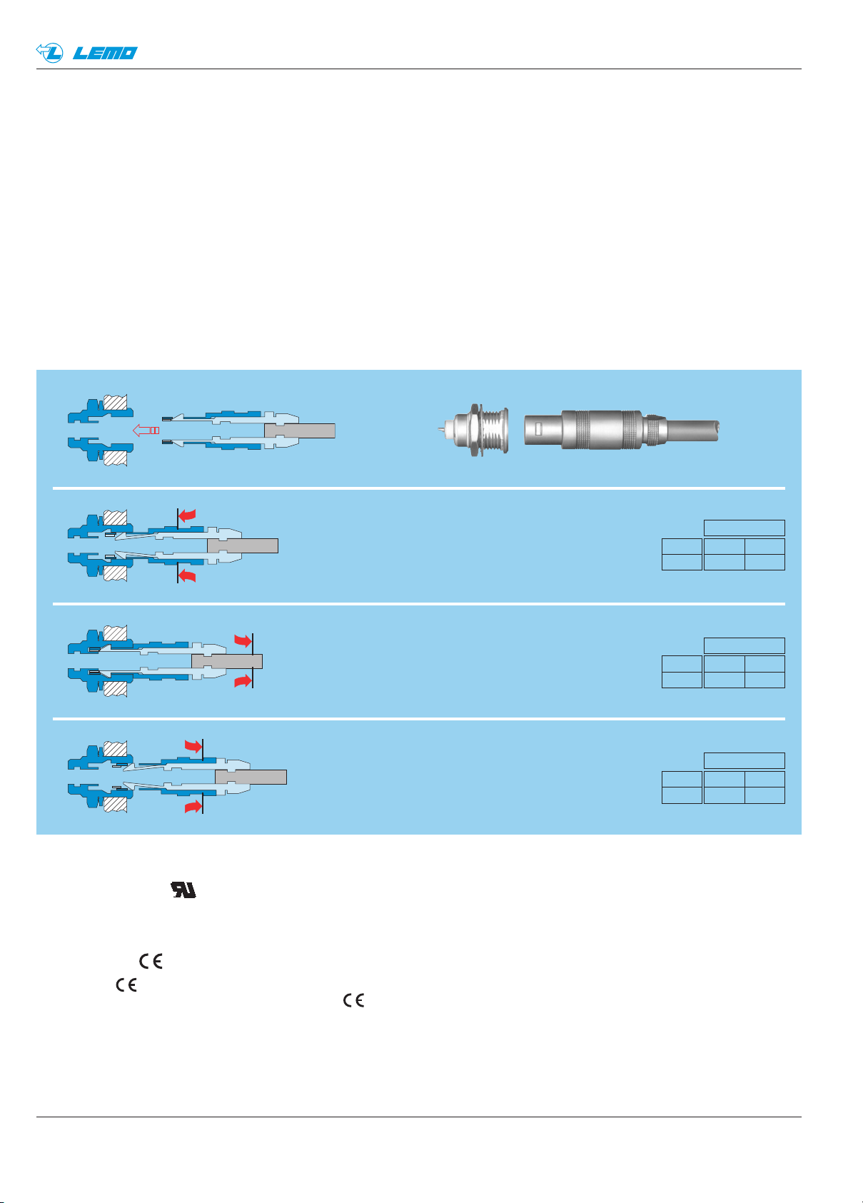
LEMO’s Push-Pull Self-Latching Connection System
This self-latching system is renowned worldwide for its easy and quick mating and unmating features. It provides
absolute security against vibration, shock or pull on the cable, and facilitates operation in a very limited space.
The LEMO self-latching system allows
the connector to be mated by simply pushing
the plug axially into the socket.
v: average latching force
F
Force
F
v
Series
00 01
9N 5N
Once firmly latched, connection cannot be broken
by pulling on the cable or any other component
part other than the outer release sleeve.
a: average pull force with axial pull on
F
Force
F
a
Series
00 01
120N 110N
the collet nut
When required, the connector is disengaged
by a single axial pull on the outer release sleeve.
This first disengages the latches and then
withdraws the plug from the socket.
d: average unmating force with axial pull
F
on the outer release sleeve.
Force measured according to the standard IEC 60512- test
Force
F
d
1N = 0,102 kg.
Series
00 01
7N 6N
UL Recognition
LEMO connectors are recognized by the Underwriters Laboratories (UL). The approval of the complete system (LEMO
connector, cable and your equipment) will be easier because LEMO connectors are recognized.
CE marking
CE marking means that the appliance or equipment bearing it complies with the protection requirements of one or
several European safety directives. CE marking applies to complete products or equipment, but not to electrome-
chanical components, such as connectors.
RoHS
LEMO connector specifications conforms the requirements of the RoHS directive (2011/65/EU) of the European Parliament and the latest amendments. This directive specifies the restrictions of the use of hazardous substances in electrical
and electronic equipment marketed in Europe.
2
www.lemo.com
Page 5
®
®
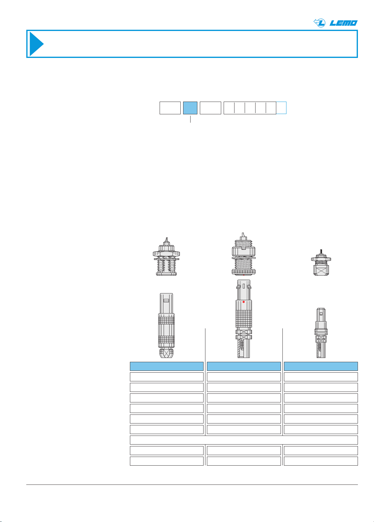
2 steps to select the right connector
● Step 1: Select connector series
Select the appropriate LEMO connector series according to the standard, the cable, according to the application or
the mated connector already on your equipment.
Part number coding
.. .
250
00 or 01 series
The NIM-CAMAC 00.250 series
The 00 series is coaxial (50 Ω ). This connectors family was conceived for all applications where a high density of
connectors is necessary, especially for patch panels. Because of LEMO’s special self-latching system, it is possible
to connect them with a simple axial push-pull thereby reducing the space needed to mount sockets to an absolute
minimum, up to 50 sockets per square decimetre. LEMO 00 connectors served as the norm for NIM-CAMAC
CD/N549 standard, used in nuclear physics as well as many other applications.
The miniature 01.250 series
The 01 series is coaxial (50 Ω ). The plugs and sockets are amongst the smallest available 50 Ω coax connectors with a
self-latching intermating capability. In spite of their small size and light weight, their technical characteristics remain
excellent. Available in a wide range of housing configurations, they are especially useful when connecting onto printed
circuit boards.
Series
Standard
Environment
Ingress Protection
Ingress Protection
Temperature range
Keying
Latching
Contact type
Cable fixing type
1)
Note:
IP50 = Protection from the amount of dust that would interfer with the operation of the equipment
2)
Ingress protection between LEMO socket and your device (IP64 = protection from splashed water and dust tight)
00
–
1)
2)
Push-Pull self-latching
IP50
IP64 models (HEV model)IP64 / watertight and vacuumtight IP50
- 55 to 260°C- 55 to 260°C
Solder, crimp or print
Crimping
0100
–NIM-CAMAC
indoorindoor indoor
IP50IP50
- 55 to 230°C
–Yes–
Solder or printSolder, crimp or print
CrimpingClamping or crimping
3www.lemo.com
Page 6
4
®
®
www.lemo.com
.. .
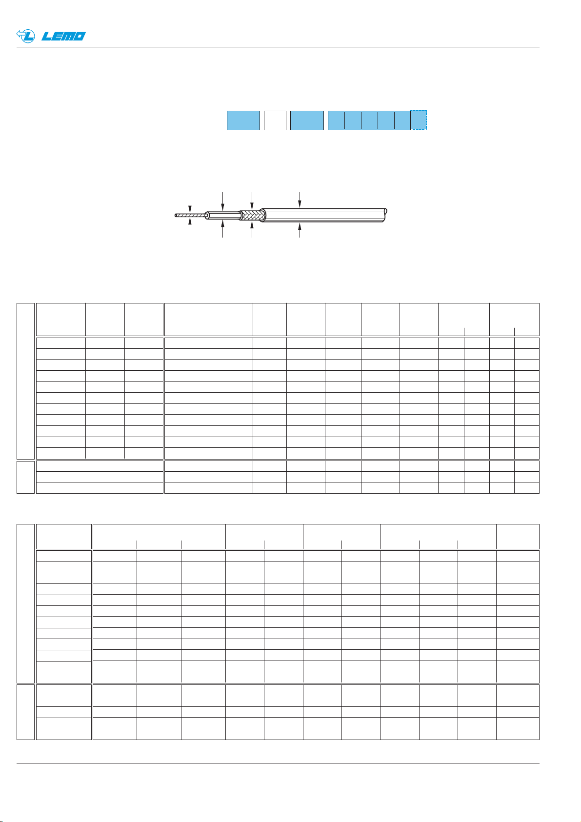
● Step 2 : Complete the part number
Complete the part numbering by choosing the model depending on your cable and the application.
Verify the fitting to your cable and cable wire
Recommended coaxial cables
250
Part number coding
19 x 0.18
solid
7 x 0.16
7 x 0.16
7 x 0.10
7 x 0.10
7 x 0.10
7 x 0.18
7 x 0.10
7 x 0.10
7 x 0.18
0.90
0.95
0.48
0.48
0.30
0.30
0.30
0.54
0.30
0.30
0.54
PE
PTFE
PE
PE
PTFE
PTFE
PTFE
PTFE
PTFE
PTFE
PTFE
2.92
2.95
1.50
1.50
0.87
1.50
1.50
1.50
2.52
0.87
1.50
CuSn
CuAg
CuAg
CuSn
CuSn
CuAg
CuAg
CuAg
CuAg
CuAg
CuAg
CuAg
3.6
1
st
: 3.53
2nd: 4.20
2.0
2.0
1.4
2.0
2.0
2.0
3.1
1.37
2.1
PVC
FEP
PVC1
PVC2
FEP
FEP
PFA
PFA
PFA
PFA
FEP
black
black
black
brown
brown
white
white
white
white
brown
Mechanical properties
Type
RG 58 C/U
RG 142 B/U
RG 174 U
RG 174 A/U
RG 178 B/U
RG 179 B/U
RG 187 A/U
RG 188 A/U
RG 195 A/U
RG 196 A/U
RG 316 /U
CuSn
CuStAg
CuSt
CuSt
CuStAg
CuStAg
CuStAg
CuStAg
CuStAg
CuStAg
CuStAg
ScreenDielectric
Mat. ø mmMat. Stranding ø mm Mat. ø mm
Conductor Sheath
Mat. Colour ø mm kg/ 100m.
3.80
6.60
1.10
0.85
1.50
1.60
1.60
2.80
1.10
1.60
4.95
4.95
2.55
2.80
1.80
2.60
2.60
2.60
3.70
2.00
2.60
7 x 0.16
7 x 0.06
7 x 0.16
0.50
0.19
0.50
PE
PFA
PTFE
1.50
0.52
1.52
CuAg
CuSn
CuAg
CuAg
CuAg
1
st
: 1.95
2nd: 2.40
0.9
1
st
: 2.00
2
nd
: 2.50
PVC
PFA
FEP
grey
white
G02232D-60
K01152-07
421-099
Cu
CuAg
CuStAg
2.10
0.90
1.95
3.10
1.25
3.05
Electrical and general properties
MIL-C-17
RG 58 C/U
RG 142 B/U
RG 174 /U
RG 174 A/U
RG 178 B/U
RG 179 B/U
RG 187 A/U
RG 188 A/U
RG 195 A/U
RG 196 A/U
RG 316 /U
50.3.1
50.2.1
50.2.1
50.1.1
75.2.1
75.2.2
50.2.3
50.1.2
50.2.2
KX 15
KX 38
KX 3A
KX 21A
KX 22A
Capaci-
tance
Impe-
dance
Ohm pF/m
IEC
60096-2
CCTU
10-01A
LEMO
Part-No
CCX.50.RG5.8CU50N
CCX.50.RG1.42BU50M
CCX.50.RG1.74U25N
CCX.50.RG1.74AU27N
CCX.50.RG1.78BU18M
CCX.75.RG1.79BU26M
CCX.75.RG1.87AU26B
CCX.50.RG1.88AU24B
CCX.95.RG1.95AU37B
CCX.50.RG1.96AU20B
CCX.50.RG3.16BU26M
50±2
50±2
50±2
50±2
50±2
75±3
75±3
50±2
95±5
50±2
50±2
101
95
101
101
96
64
64
96
49
96
96
Atte -
nuation
23
12.8
35
31.5
48
33
33
33
17
48
33
Operating
voltage
1.90
1.50
2.50
1.50
0.70
1.20
1.20
1.20
1.50
0.70
1.20
U max. KV eff.
Temperature
°C
from to
db/100 m
at 100 MHz
Series
•
•
••
••
••
••
••
••
•
••
••
-25 +70
-70 +200
-40 +75
-25 +70
-90 +205
-90 +205
-50 +205
-50 +205
-90 +205
-50 +205
-90 +205
00 01
50±2
50±5
50±2
101
96
96
24
72
72
1.50
0.45
2.50
•
•
•
-40 +105
-45 +165
-40 +75
Non
standard
Non
standard
Standard
Standard
Weight
Huber+Suhner G02232D-60
Huber+Suhner K01152-07
Storm 421-099
LEMO
Cable
group
6
7
3
8
1
2
2
4
5
1
4
8
9
8
conductor
screen
sheathdielectric
Page 7
5www.lemo.com
®
®
00 SERIES (NIM-CAMAC)
Page 8
®
®
Watertight or vacuumtight models (page 22)
Straight plug Elbow sockets Fixed sockets
Metal housing models with mechanical keying* (page 24)
Plastic housing models* (page 21)
Straight plugsFixed plugs Free socketsFixed sockets Elbow sockets
Fixed coupler
Free coupler
FAA FFA
FFA
ERA, ERE
EPL, EPM, EPK, EPR
PCA
RAD
Metal housing models (page 8)
Fixed sockets
FFC
FFC ERX
FFA
ERT
ERC
ERN
EPY
EPN
EPS
PSA
PSS
PES
PCS
RMA
FAN
FAB
FPA
FPL
Straight and
elbow plugs
with socket
FTR
FTA
FTL
Elbow plugs
FFY
FFE
FFS
FFF
FLS,
FLV
ECP
EHP
ELF
PFS
PLK
Plugs with
resistor
FLR
FRT
Socket with
microswitch
EPA, EPB, EPC
EPE
ERM
ERN FVS
FTY
FFA
Straight sockets
Adaptors
(See page 27)
Threaded latching Models*
(page 26)
HGP
HGW
HEP EWF
VPSSWH
FSG XBG XRG XSG EXG ESGPSG
EWV
Fixed socketStraight plug Straight plug
Straight coupler
FLS.NTAE
FLC
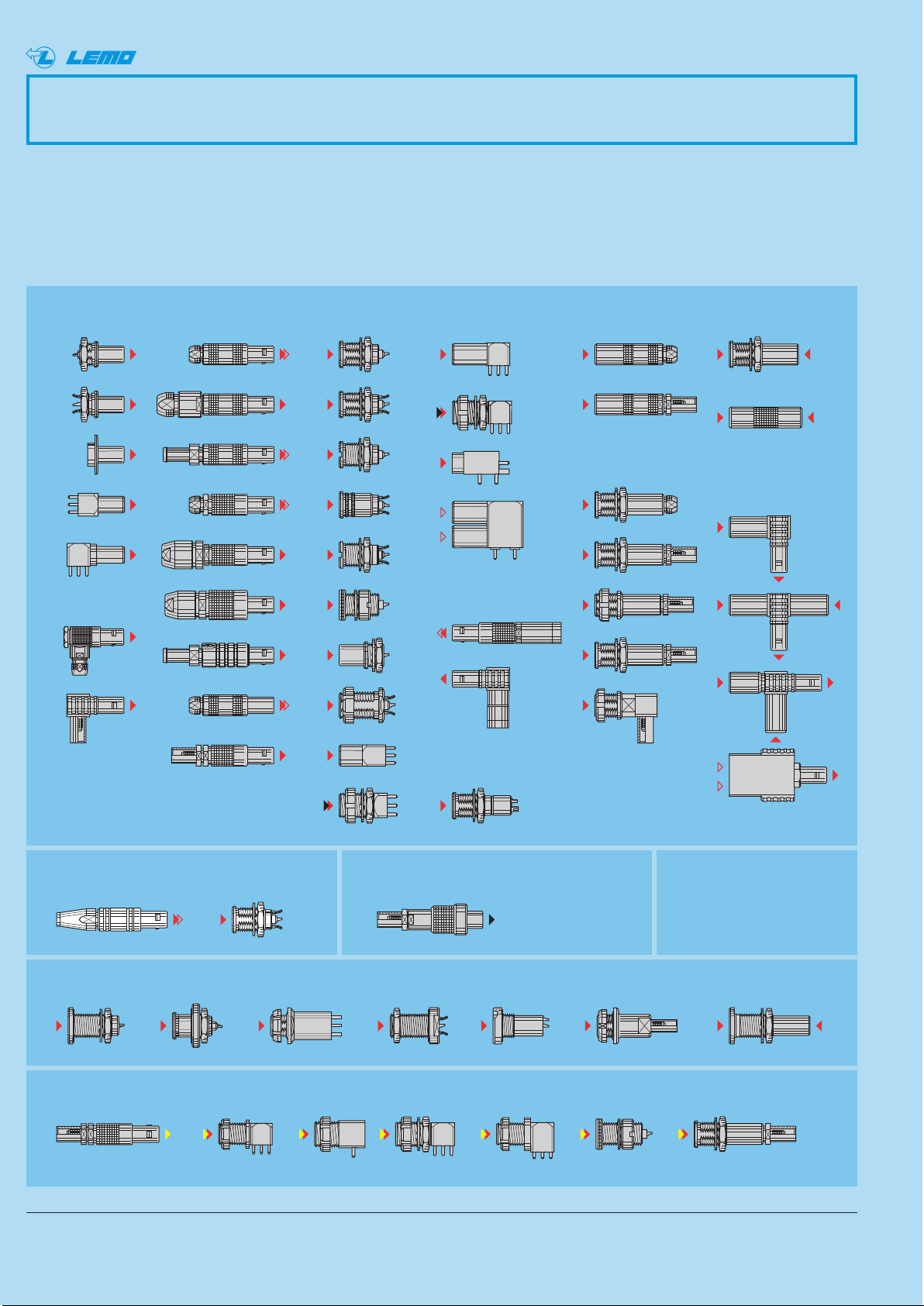
00 Series (NIM-CAMAC CD/N 549)
The 00 series is a range of 50 Ω coaxial connectors. They are suitable for a wide variety of applications particularly in
measurement, control system and nuclear physics, having formed the basis for the NIM-CAMAC CD/N 549 standard.
LEMO 00 connectors offer customers many benefits including:
– Self-latching push-pull system – High packing density – Low weight
– Aesthetically pleasing appearance – Rugged construction – Reliable performances
– Small size – Ease of use – Wide choice to suit application
* not included in NIM-CAMAC standard
6 www.lemo.com
Page 9
7www.lemo.com
®
1
4
5
2
67
3
4
3
1
2
1
4
5
2
67
3
4
3
1
2
8
6
5
7
6
5
7
8
PCA
FFA 00
Cable ø
Collet type:
C = with cable collet clamping
E = with cable crimping
K, D = with oversize cable collet
250
Insert configuration:
250 = coaxial (50 Ω)
Housing :
N = brass nickel-plated
4)
C = brass chrome-plated
4) 1)
D = brass gold-plated
5)
K = brass black chrome
1)
G = PEEK
2)
Model: (page 8)
Series: 00
NTAC29
Fixed socket
ERA 00
250
NTL
Insulator:
T = PTFE
L = PEEK
5)
Variant: (page 30)
Contact type:
A = male solder
D = male print
L = female solder
N = female print
Variant: (page 30)
Fixed coupler
RAD 00
250
NTM
Part Numbering System
Plug
00
250
NTLC29
Free socket
Part Section Showing Internal Components
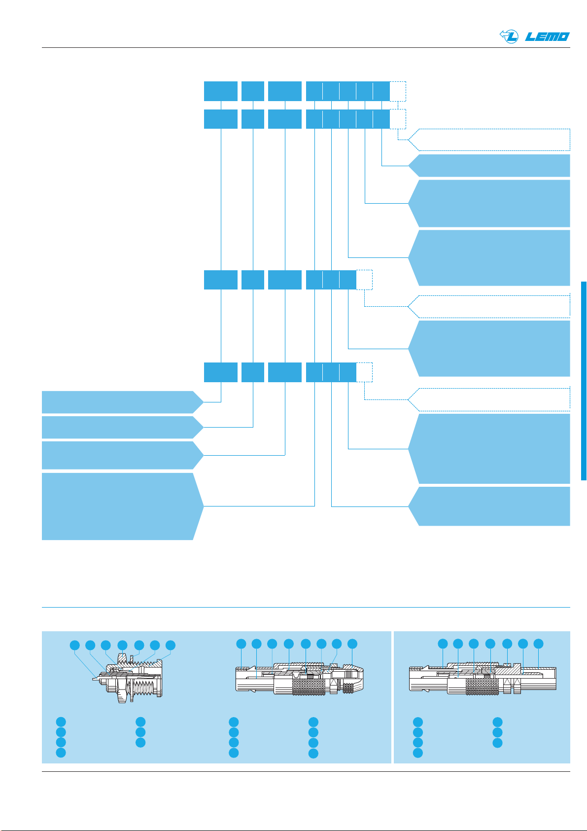
Part Number Example
.. .
.. .
.. .
.. .
Variant: (page 30)
6
5
7
1
4
5
2
6
7
3
4
3
1
2
outer shell
earthing crown
retaining ring
hexagonal nut
Fixed socket
outer shell
latch sleeve
collet nut
earthing sleeve
Plug with cable clamping
locking washer
insulator
female contact
rear insulator
insulator
male contact
collet
outer shell
latch sleeve
crimp backnut
rear insulator
Plug with cable crimping
insulator
male contact
crimp ferrule
FFA.00.250.NTAC29 = straight plug with cable collet, series 00, coaxial type (50 Ω), outer shell in nickel-plated brass,
PTFE insulator, male solder contact, C type collet of 2.9 mm diameter.
Note: 1) treatment not available for the printed circuit models
2) available for the FFA and ERN model only
3) used only for models : FTA, FTL and FTY.
4) standard
5) non-standard, on request only
Contact type:
A = male solder
C = male crimp
L = female solder
M = female crimp
Contact type:
A = male-female
E = male-male-female
3)
F = female-female-male
L = female-male
M = female-female
®
Page 10
1
2
8 www.lemo.com
®
®
Metal housing models
~18
~26
S 4.5
ø 6.4
FFA Straight plug with cable collet
M1
Cable assembly, solder contact (page 39)
Part number
FFA.00.250.NTAC15
FFA.00.250.NTAC17
FFA.00.250.NTAC22
FFA.00.250.NTAC27
FFA.00.250.NTAC31
Cable Cond. Dielectric Ø Sheath Ø
group Ø max. max. min. max.
9 0.55 1.45 1.1 1.4
– 0.55 1.45 1.3 1.7
1 0.55 1.95 1.8 2.2
2-3-4 0.55 1.95 2.3 2.7
8 0.55 1.95 2.8 3.0
Characteristics
Value Standard Test
Contact retention force
Cable pull off force
1)
Connector pull off force
Endurance
Operating temperature
> 18 N IEC 60512-8 15a
> 100 N IEC 60512-9 17c
> 90 N IEC 60512-8 15f
> 5000
IEC 60512-5 9a
cycles
- 55°C + 260°C
Characteristics
Value Standard Test
Impedance
Operating voltage (50 Hz)
Test voltage (50 Hz)
Rated current
Contact resistance
Shell electrical continuity
Insulating resistance
VSWR
Shielding efficiency
50 Ω –
0.7 kV rms –
2.1 kV rms IEC 60512-2 4a
4 A IEC 60512-3 5a
< 6 mΩ IEC 60512-2 2a
< 3.5 mΩ IEC 60512-2 2f
> 1012Ω IEC 60512-2 3a
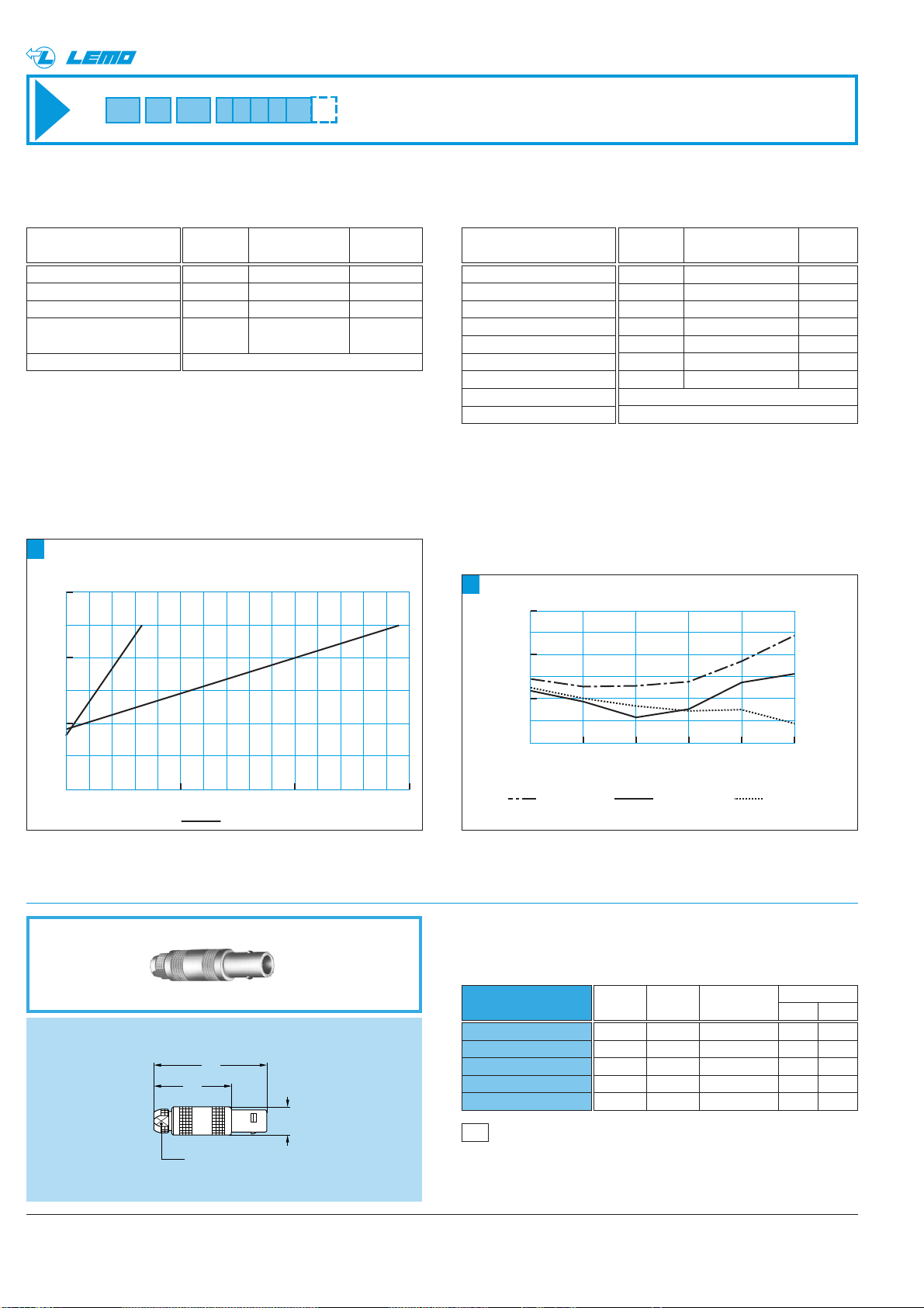
see chart N°1 below
see chart N°2 below
Mechanical and climatical Electrical
Technical Characteristics
Note: 1)depending on cable design
Voltage Standing Wave Ratio
The VSWR (Voltage Standing Wave Ratio) is the value
representing the power reflected in a connection. The
VSWR varies with frequency, in most cases, the working
frequency range is where VSWR is ≤ 1.25.
75
Ω
1500 500 1000 f
1.1
1.0
VSWR
FFS + PCS
1.2
1.3
50Ω
Note: value for connectors with PTFE insulator. VSWR measured
50 Ω with a RG-174 A/U cable and 75 Ω with a RG-179 B/U cable.
Measured according to IEC-60169-1-1.
Shielding efficiency (EMC properties) in dB
(transfer impedance in dBohm)
The shielding efficiency is the ratio between the electromagnetic field inside the connector and a power source
at the outside of the connector (or vice versa).
Note: measured according to IEC-60169-1-3 standard.
(dB
Ω
)
-10
-20
(dB)
60
80
-30
-40
0.01 0.1 1 10 100 1000 f
FFA + PCA FFS + PCS FFV + PCS
100
120
(MHz)
Page 11
9www.lemo.com
®
®
FFC.00.250.CTAC22
FFC.00.250.CTAC27
FFC.00.250.CTAC31
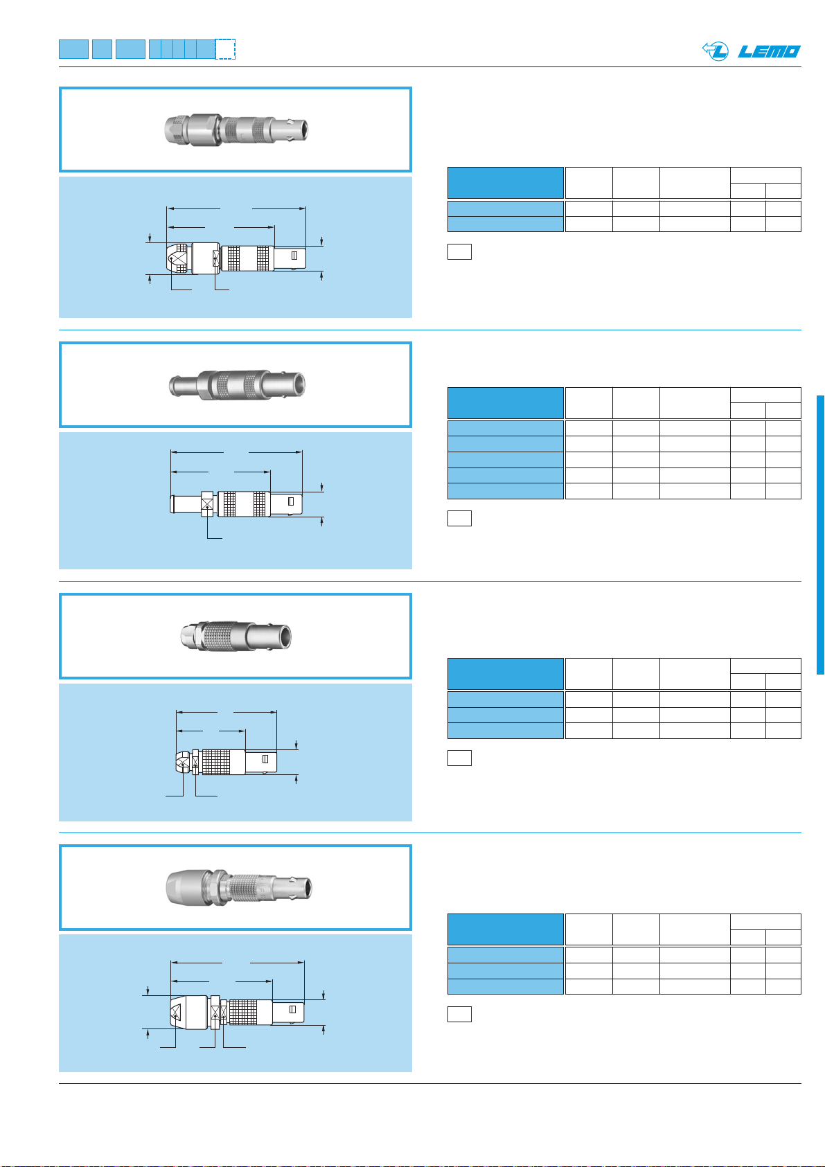
FFC Straight plug with flats on latch sleeve
and cable collet
M3
Cable assembly, solder contact (page 39)
Part number
Cable Cond. Dielectric Ø Sheath Ø
group Ø max maxi mini maxi
1 0.60 1.55 1.7 2.1
2-3-4 0.60 1.95 2.3 2.7
8 0.60 1.95 2.8 3.0
FFC.00.250.CTAD42
FFC.00.250.CTAD52
FFC.00.250.CTAD56
M3
Cable assembly, solder contact (page 39)
Part number
Cable Cond. Dielectric Ø Sheath Ø
group Ø max maxi mini maxi
5 1.05 3.05 3.1 4.0
6-7 1.05 3.05 4.1 5.0
– 1.05 3.05 5.1 5.5
FFC Straight plug with flats on latch sleeve
and oversize cable collet
FFA Straight plug with oversize cable collet
FFA
Note: the bend relief must be ordered separately (see page 30).
Straight plug with cable collet
and nut for fitting a bend relief
M1
Cable assembly, solder contact (page 39)
Part number
FFA.00.250.NTAK37
FFA.00.250.NTAK42
Cable Cond. Dielectric Ø Sheath Ø
group Ø max maxi mini maxi
8 0.55 1.95 3.0 3.6
– 0.55 1.95 3.3 4.1
M1
Cable assembly, solder contact (page 39)
Part number
FFA.00.250.NTAC15Z
FFA.00.250.NTAC17Z
FFA.00.250.NTAC22Z
FFA.00.250.NTAC27Z
FFA.00.250.NTAC31Z
Cable Cond. Dielectric Ø Sheath Ø
group Ø max maxi mini maxi
9 0.55 1.45 1.1 1.4
– 0.55 1.45 1.3 1.7
1 0.55 1.95 1.7 2.1
2-3-4 0.55 1.95 2.3 2.7
8 0.55 1.95 2.8 3.0
ø 8
~ 28.5
S 7S 6.5
~25.5
S 6
~ 36.5
~33.5
ø 6.4
ø 6.4
S 5
~18
S 5.5
~26
~26.5
~34.5
ø 6.4
ø 8.6
S 5.5
S 8S 7
ø 6.4
Page 12
10 www.lemo.com
®
®
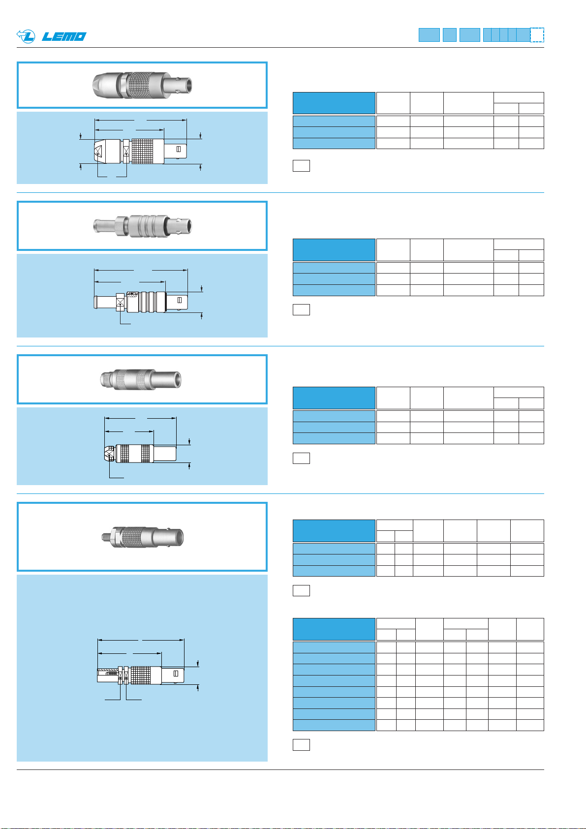
FFE Straight plug with front sealing ring,
cable collet and nut for fitting a bend relief
(IP 54 protection index when mated)
Note: the bend relief must be ordered separately (see page 30).
M
L
ø 6.4
S 5.5S 5.5
FFS Straight plug for cable crimping
~18
~26
S 4.5
ø 6.4
FFF Straight plug, non-latching,
with cable collet
M4
Cable assembly, crimp contact (page 40)
M5
Cable assembly, solder contact (page 41)
FFE.00.250.NTAC22Z
FFE.00.250.NTAC27Z
FFE.00.250.NTAC31Z
M1
Cable assembly, solder contact (page 39)
Part number
Cable Cond. Dielectric Ø Sheath Ø
group Ø max maxi mini maxi
1 0.55 1.95 1.7 2.1
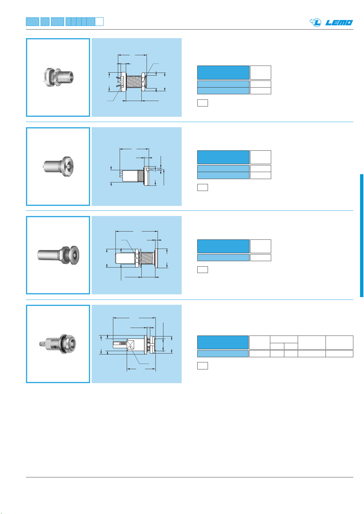
2-3-4 0.55 1.95 2.3 2.7
8 0.55 1.95 2.8 3.0
FFF.00.250.NTAC22
FFF.00.250.NTAC27
FFF.00.250.NTAC31
M1
Cable assembly, solder contact (page 39)
Part number
Cable Cond. Dielectric Ø Sheath Ø
group Ø max maxi mini maxi
1 0.55 1.95 1.7 2.1
2-3-4 0.55 1.95 2.3 2.7
8 0.55 1.95 2.8 3.0
Part number
FFS.00.250.CTCE24
FFS.00.250.CTCE25
FFS.00.250.CTCE30
FFS.00.250.CTCE31
FFS.00.250.CTCE35
FFS.00.250.CTCE44
FFS.00.250.CTCE52
FFS.00.250.CTCE56
Dim Cable Cond. Ø Dielec. Sheath
L M group mini maxi Ø maxi Ø maxi
31 23 1 0.28 0.4 0.95 2.35
31 23 1 0.28 0.4 1.15 2.35
31 23 2 0.28 0.4 1.65 3.0
31 23 3-4 0.46 0.55 1.65 3.0
31 23 8 0.46 0.55 1.65 3.35
31 23 5 0.28 0.4 2.65 4.35
34 26 6 0.90 0.97 3.05 5.2
34 26 7 0.90 0.97 3.05 5.45
FFY.00.250.NTAC40
FFY.00.250.NTAC47
FFY.00.250.NTAC52
M2
Cable assembly, solder contact (page 39)
Part number
Cable Cond. Dielectric Ø Sheath Ø
group Ø max maxi mini maxi
5 1.05 3.05 3.2 3.8
– 1.05 3.05 3.9 4.5
6-7 1.05 3.05 4.6 5.0
FFY Straight plug, large shell with cable collet
Part number
FFS.00.250.CTAE24
FFS.00.250.CTAE31
FFS.00.250.CTAE52
Dim Cable Cond. Dielec. Sheath
L M group Ø maxi Ø maxi Ø maxi
31 23 1 0.4 0.95 2.35
31 23 3-4 0.55 1.65 3.0
34 26 6 0.97 3.05 5.2
ø 8.6
S 7
S 8
~25
~25.5
S 6
~33
~33.5
ø 8.9
ø 7.4
Page 13
®
®
M
L
ø 6.4
S 5.5S 5.5
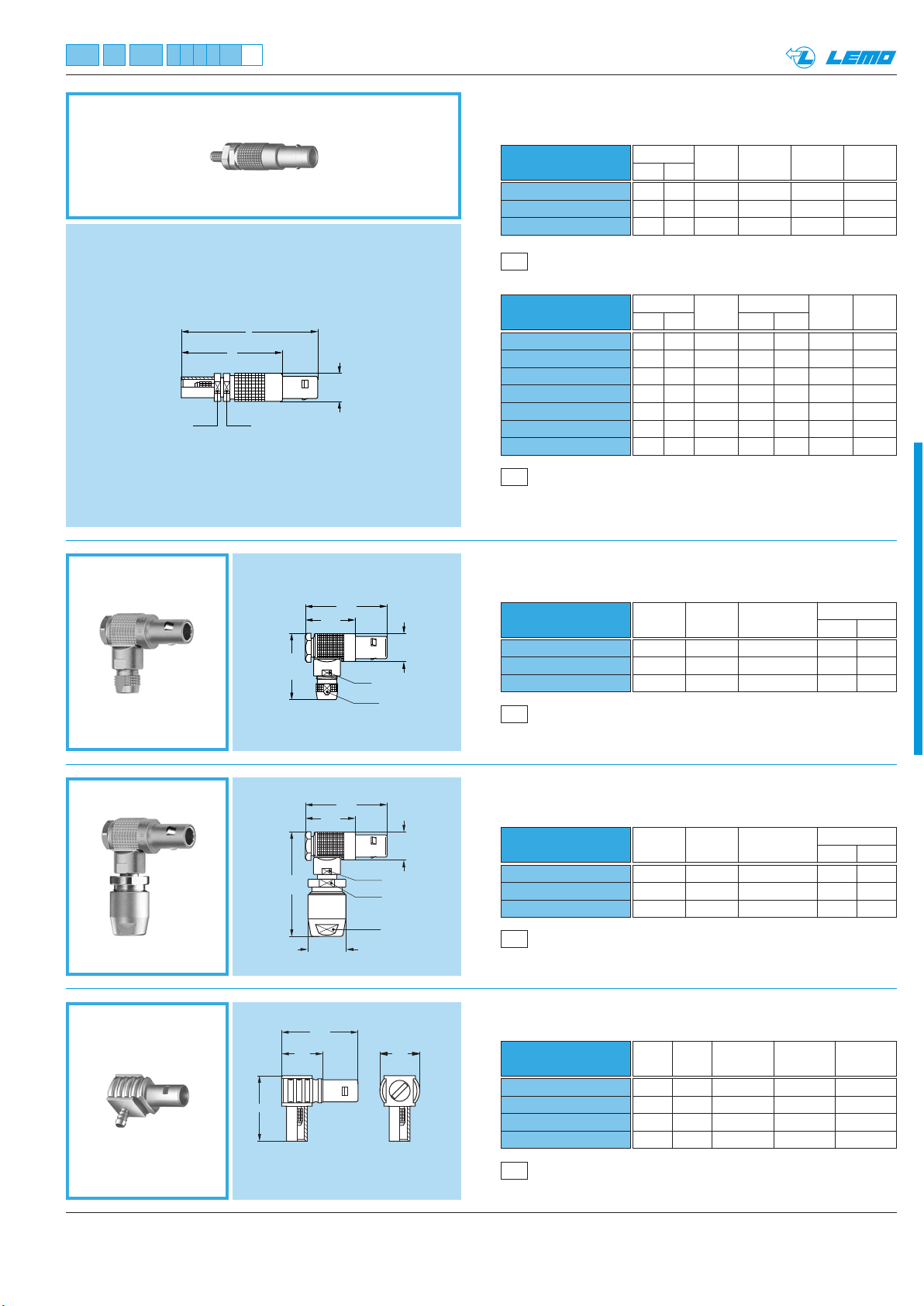
FFV Straight plug for cable crimping
with improved screen efficiency
Part number
FFV.00.250.NTAE24
FFV.00.250.NTAE31
FFV.00.250.NTAE52
Cable assembly, solder contact (page 41)
M5
Part number
FFV.00.250.NTCE24
FFV.00.250.NTCE30
FFV.00.250.NTCE31
FFV.00.250.NTCE35
FFV.00.250.NTCE44
FFV.00.250.NTCE52
FFV.00.250.NTCE56
Cable assembly, crimp contact (page 40)
M4
Dim Cable Cond. Dielec. Sheath
L M group Ø maxi Ø maxi Ø maxi
31 23 1 0.4 0.95 2.35
31 23 3-4 0.55 1.65 3.0
34 26 6 0.97 3.05 5.2
Dim Cable Cond. Ø Dielec. Sheath
L M group mini maxi Ø maxi Ø maxi
31 23 1 0.28 0.4 0.95 2.35
31 23 2 0.28 0.4 1.65 3.0
31 23 3-4 0.46 0.55 1.65 3.0
31 23 8 0.46 0.55 1.65 3.35
31 23 5 0.28 0.4 2.65 4.35
34 26 6 0.90 0.97 3.05 5.2
34 26 7 0.90 0.97 3.05 5.45
1)
Note:1)Screen efficiency >100dB at 1 GHz, see page 8.
FLC Elbow plug (90°) with cable collet
~16.5
11.5
19.5
S 6
S 4.5
ø 7.5
Part number
FLC.00.250.CTAC22
FLC.00.250.CTAC27
FLC.00.250.CTAC31
M6
Cable assembly, solder contact (page 42)
Cable Cond. Dielectric Ø Sheath Ø
group Ø max maxi mini maxi
1 0.55 1.55 1.7 2.1
– 0.55 1.75 2.3 2.7
– 0.55 1.75 2.8 3.0
FLC Elbow plug (90°) with oversize cable collet
19.5
11.5
Part number
FLC.00.250.CTAD42
FLC.00.250.NTAD52
~25
ø 7.5
S 6
S 8
FLC.00.250.NTAD56
S 7
M6
Cable assembly, solder contact (page 42)
FLS
Elbow plug (90°) for cable crimping
Part number
9.5
ø 8.5
17.5
ø 9
FLS.00.250.NTAE31
H
FLS.00.250.NTAE35
FLS.00.250.NTAE52
FLS.00.250.NTAE56
Cable Cond. Dielectric Ø Sheath Ø
group Ø max maxi mini maxi
8 0.97 1.75 3.1 4.0
6 0.97 1.75 4.1 5.0
7 0.97 1.75 5.1 5.5
H Cable Cond. Dielectric Sheath
(mm) group Ø maxi Ø maxi Ø maxi
15 – 0.55 1.65 3.0
15 – 0.55 1.65 3.35
18 6 0.97 3.05 5.2
18 7 0.97 3.05 5.45
M7
Cable assembly, solder contact (page 42)
11www.lemo.com
Page 14
®
®
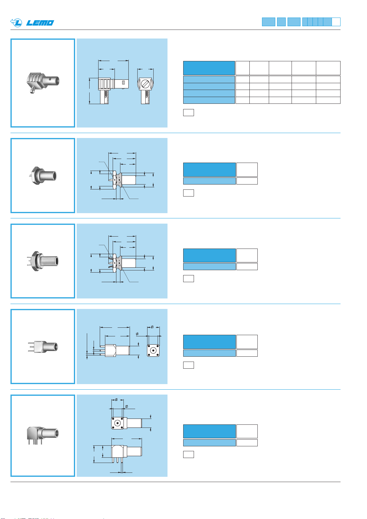
FLV Elbow plug (90°) for cable crimping
with improved screen efficiency *
H
ø 10.2
ø 10.2
S 9
M7x0.5
2 maxi
S 9
M7x0.5
9.5
17.5
15.6
15.6
ø 9
Part number
FLV.00.250.NTAE31
FLV.00.250.NTAE35
FLV.00.250.NTAE52
FLV.00.250.NTAE56
M7
Cable assembly, solder contact (page 42)
H Cable Cond. Dielectric Sheath
(mm) group Ø maxi Ø maxi Ø maxi
15 3-4 0.55 1.65 3.0
15 8 0.55 1.65 3.35
18 6 0.97 3.05 5.2
18 7 0.97 3.05 5.45
* Screen efficiency >100dB at 1 GHz, see page 8.
FAA Straight plug, non-latching, nut fixing
13
9
Part number
ø 8
ø 5
S 6.3
FAA.00.250.NTA
P5
Panel cut-out (page 38)
Weight
(g)
2.5
FAN Straight plug, non-latching,
nut fixing with earthing tags
13
9
Weight
(g)
2.5
ø 5
ø 8
Part number
FAN.00.250.CLA
ø 1
ø 0.7 (4x)
10
2 maxi
7
P5
S 6.3
Panel cut-out (page 38)
FPA Straight plug, non-latching,
for printed circuit
5.08
ø 5
ø 5
7
Part number
FPA.00.250.NTD
P11
PCB drilling pattern (page 38)
Weight
(g)
2.5
FPL Elbow plug (90°), non-latching
for printed circuit
Part number
FPL.00.250.NTD
P10
PCB drilling pattern (page 38)
Weight
(g)
2.5
17
14
7
5.08
17.5
ø 0.7 (5x)
12 www.lemo.com
Page 15
13www.lemo.com
®
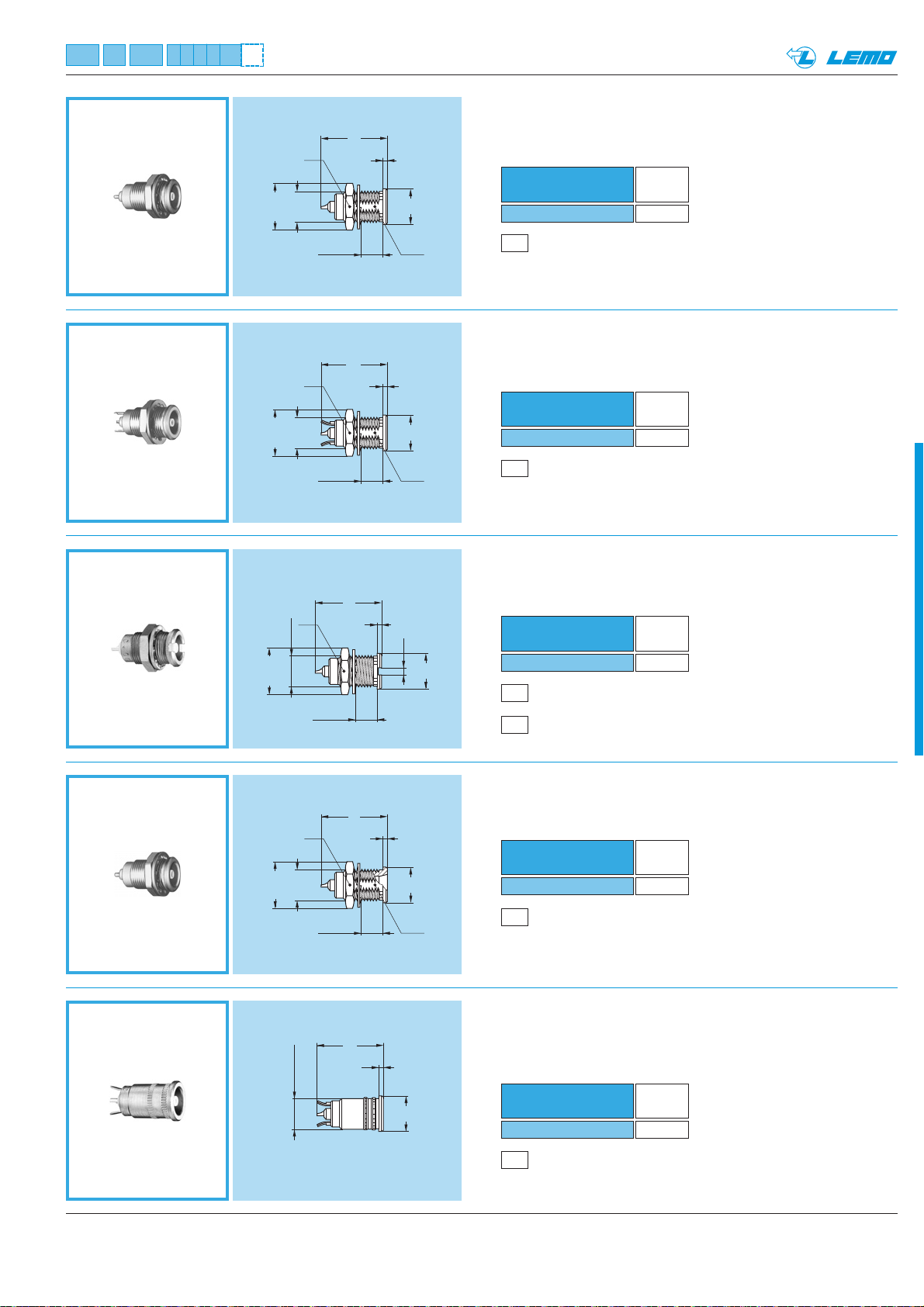
ø 10.2
ERA Fixed socket, nut fixing
ERN Fixed socket, nut fixing,
with earthing tags
Part number
ERA.00.250.NTL
Weight
(g)
2.5
P5
Panel cut-out (page 38)
Part number
ERN.00.250.NTL
Weight
(g)
2.5
P5
Panel cut-out (page 38)
ERC Fixed socket, with thread,
with slots in flange
Part number
ERC.00.250.NTL
Weight
(g)
2.6
P1
Panel cut-out (page 38)
P3
Panel cut-out for use wihout hexagonal nut (page 38)
ERT Straight socket without thread,
force or adhesive fit, with earthing tags
Part number
ERT.00.250.NTL
Weight
(g)
2.1
P4
Panel cut-out (page 38)
ERE Fixed socket, nut fixing,
with conical lead-in
Part number
ERE.00.250.NTL
Weight
(g)
2.8
P5
Panel cut-out (page 38)
ø 10.2
S 9
M7x0.5
S 9
M7x0.5
5.5 maxi
5.5 maxi
®
15
1
S 6.3
ø 8
15
1
S 6.3
ø 8
ø 10.2
ø 10.2
S 9
M7x0.5
S 9
M7x0.5
5.5 maxi
5.5 maxi
15
1
1.6
ø 8
15
1
S 6.3
ø 8
15
1
6.98 ±0.03
ø 8
Page 16
14 www.lemo.com
®
®
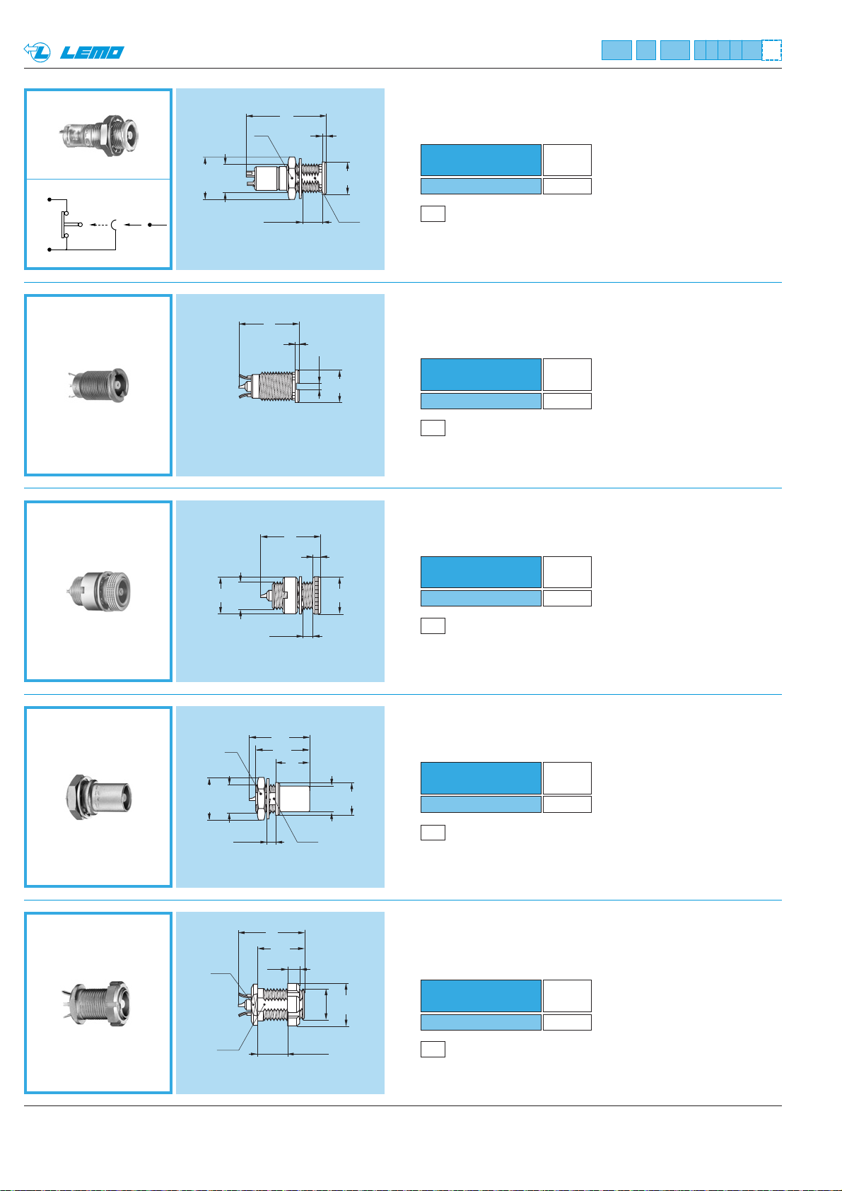
ELF Fixed socket, with slotted nut,
long threaded shell, with earthing tags
(back panel mounting)
Part number
ELF.00.250.NTL
Weight
(g)
3.1
P5
Panel cut-out (page 38)
P5
Panel cut-out (page 38)
A
B
ECP Fixed socket with two nuts
ERM Fixed socket, nut fixing, with microswitch
ERX Fixed socket, with thread, with slots
in flange, with earthing tags
Part number
ERM.00.250.NTL
Weight
(g)
3.0
P5
Panel cut-out (page 38)
P3
Panel cut-out (page 38)
Technical characteristics on request
Part number
ERX.00.250.NTL
Weight
(g)
2.0
Part number
ECP.00.250.NTL
Weight
(g)
3.3
P1
Panel cut-out (page 38)
EHP Fixed socket, nut fixing,
protruding shell
Part number
EHP.00.250.NTL
Weight
(g)
2.8
20
S 9
1
ø 10.2
M7x0.5
ø 9
M7x0.5
5.5 maxi
15
1
4 maxi
S 6.3
ø 8
1.6
ø 8
15
2
ø 9
S 9
ø 10.2
M7x0.5
2 maxi
15
13.5
8.5
S 6.3
ø 6.4
ø 8
15
10.5
S 7.5
S 6.3
2.5
1.5 mini
7.0 maxi
M7x0.5
ø 10
Page 17
15www.lemo.com
®
®
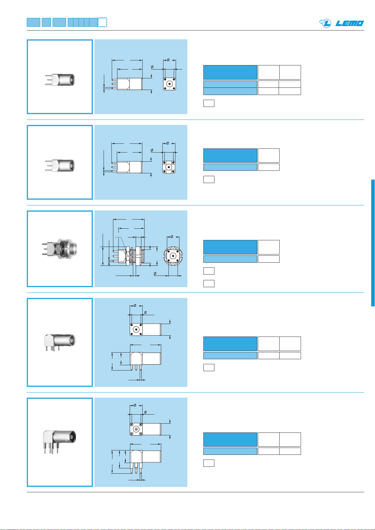
EPA-EPB Straight socket for printed circuit
EPC Straight socket for printed circuit
with clearance under the body
Part number
EPA.00.250.NTN
EPB.00.250.NTN
L Weight
(mm) (g)
14 3.4
12 3.3
P10
PCB drilling pattern (page 38)
Part number
EPC.00.250.NTN
Weight
(g)
3.3
P10
PCB drilling pattern (page 38)
EPE Fixed socket with two nuts,
for printed circuit
Part number
EPE.00.250.NTN
Weight
(g)
4.3
P1
Panel cut-out (page 38)
P12
PCB drilling pattern
(page 38)
EPM Elbow socket (90°) for printed circuit,
elevated solder tail
Part number
EPM.00.250.NTN
H Weight
(mm) (g)
13 4.6
P10
PCB drilling pattern (page 38)
EPL Elbow socket (90°)
for printed circuit
Part number
EPL.00.250.NTN
H Weight
(mm) (g)
10 4.3
P10
PCB drilling pattern (page 38)
ø 0.7 (5X)
ø 0.7 (5x)
ø 10.2
ø 0.7 (5x)
S 9
3.5 maxi
5.08
ø 6.8
7
17
L
5.08
ø 6.8
7
17
14
17
14
2.5
M7x0.5
7
ø 10
5.08
10
13
7
ø 0.7 (5x)
7
10
ø 0.7 (5x)
7
5.08
ø 6.8
17.5
7
5.08
ø 6.8
17.5
Page 18
16 www.lemo.com
®
®
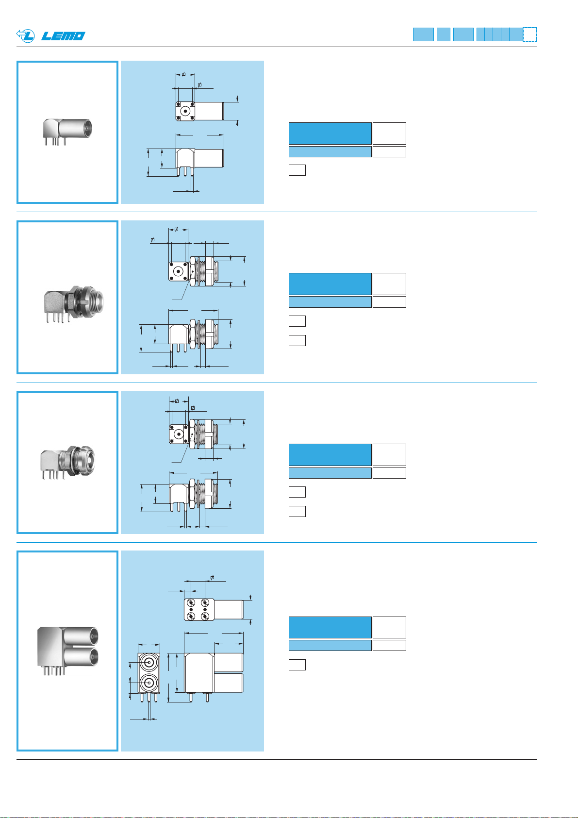
EPK Elbow socket (90°) for printed circuit
with clearance under the body
EPS Elbow socket (90°) with two nuts,
for printed circuit
Part number
EPK.00.250.NTN
Weight
(g)
4.2
P10
PCB drilling pattern (page 38)
Part number
EPS.00.250.NTN
Weight
(g)
5.4
P1
Panel cut-out (page 38)
P12
PCB drilling pattern
(page 38)
EPR Elbow socket (90°) with two nuts
for printed circuit, with clearance
under the body (back panel mounting)
Part number
EPR.00.250.NTN
Weight
(g)
5.4
EPY Elbow socket (90°) for printed circuit,
with two vertical sockets
P13
PCB drilling pattern
(page 38)
Part number
EPY.00.250.NTN
Weight
(g)
12.8
P1
Panel cut-out (page 38)
P12
PCB drilling pattern
(page 38)
7
5.08
ø 6.8
17.5
7
10
ø 0.7 (5x)
7
5.08
S 9
17.5
7
10
2.5
M7x0.5
ø 10
ø 10.2
ø 0.7 (5x)
7
10
8
ø 0.7
2.42
S 9
4 maxi
7
5.08
ø 10.2
M7x0.5
2.5
17.5
ø 10
(5x)
4 maxi
5.08
ø 6.8
21.5
10.5
7.53.9
ø 0.7 (6x)
17.8
14.3
Page 19
17www.lemo.com
®
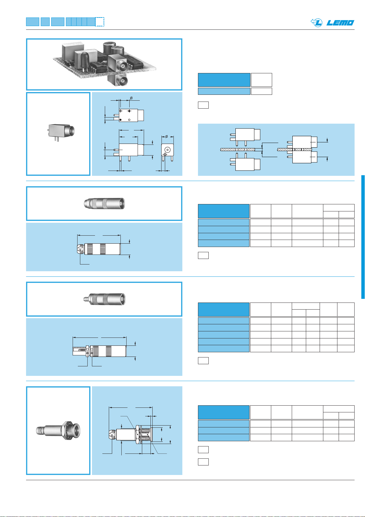
EPN Straight socket for press mounting
in pair on printed circuit
1.7 maxi
1.3 mini
8.7 maxi
8.3 mini
P9
PCB drilling pattern (page 38)
Part number
EPN.00.250.NTN
Weight
(g)
3.6
PCA Free socket with cable collet
PCA.00.250.NTLC15
PCA.00.250.NTLC22
PCA.00.250.NTLC27
PCA.00.250.NTLC31
M1
Cable assembly (page 39)
Part number
Cable Cond. Dielectric Ø Sheath Ø
group Ø max maxi mini maxi
9 0.55 1.45 1.1 1.4
1 0.55 1.95 1.7 2.1
2-3-4 0.55 1.95 2.3 2.7
8 0.55 1.95 2.8 3.0
PCS Free socket for cable crimping
Part number
PCS.00.250.NTME24
PCS.00.250.NTME30
PCS.00.250.NTME31
PCS.00.250.NTME44
PCS.00.250.NTME52
Dim Cable Cond. Ø Dielec. Sheath
L group mini maxi Ø maxi Ø maxi
30 1 0.28 0.4 0.95 2.35
30 2 0.28 0.4 1.65 3.0
30 3-4 0.46 0.55 1.65 3.0
30 5 0.28 0.4 2.65 4.35
33 6 0.90 0.97 3.05 5.2
M4
Cable assembly, crimp contact (page 40)
PSA Fixed socket, nut fixing, with cable collet
M1
Cable assembly (page 39)
P5
Panel cut-out (page 38)
Part number
PSA.00.250.NTLC22
PSA.00.250.NTLC27
PSA.00.250.NTLC31
Cable Cond. Dielectric Ø Sheath Ø
group Ø max maxi mini maxi
1 0.55 1.95 1.7 2.1
2-3-4 0.55 1.95 2.3 2.7
8 0.55 1.95 2.8 3.0
®
S 4.5
0.8
10.7
3.5 ø 1.5
ø 0.9 (2x) 2
~25
14
ø 6.5
5.08
ø 6
7
S 5.5 S 5.5
L
ø 6.5
S 4.5
S 9
5.5 maxi
M7x0.5
~25
1
ø 8
S 6.3
ø 10.2
Page 20
P5
Panel cut-out (page 38)
P5
Panel cut-out (page 38)
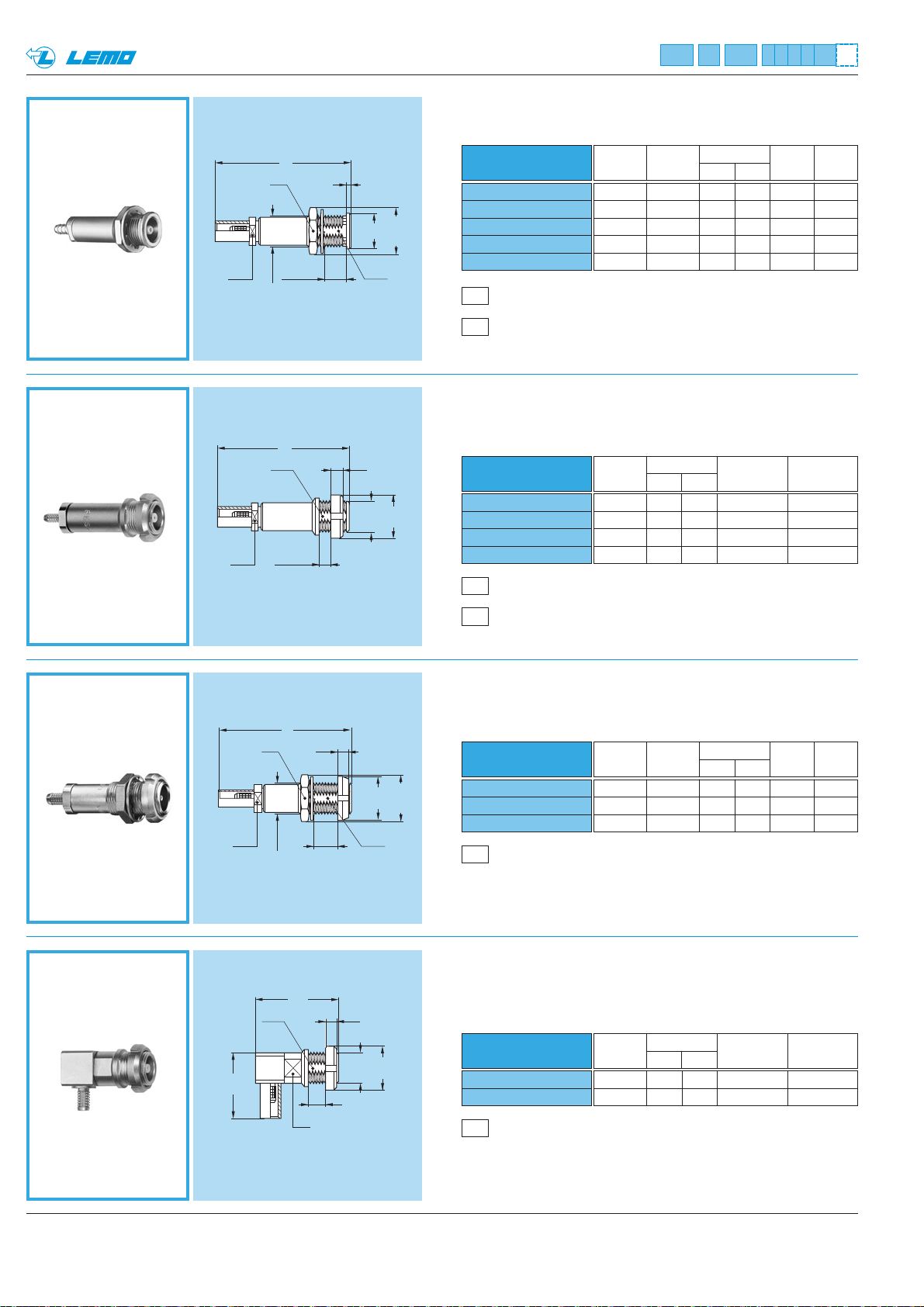
PSS Fixed socket, nut fixing, for cable crimping
M4
Cable assembly, crimp contact (page 40)
P5
Panel cut-out (page 38)
18 www.lemo.com
®
®
PFS Fixed socket, with two nuts, for cable crimping
(back panel mounting)
PLK Fixed elbow socket (90°), for cable crimping
(back panel mounting)
PES Fixed socket, nut fixing, for cable crimping
(back panel mounting)
M4
Cable assembly, crimp contact (page 40)
P5
Panel cut-out (page 38)
Part number
PLK.00.250.NTLE31
PLK.00.250.NTLE35
Part number
PES.00.250.NTME24
PES.00.250.NTME30
PES.00.250.NTME31
PES.00.250.NTME35
Cable Cond. Ø Dielectric Ø Sheath Ø
group mini maxi maxi maxi
1 0.28 0.4 0.95 2.35
2 0.28 0.4 1.65 3.0
3-4 0.46 0.55 1.65 3.0
8 0.46 0.55 1.65 3.35
Cable Cond. Ø Dielectric Ø Sheath Ø
group mini maxi maxi maxi
3-4 0.46 0.55 1.65 3.0
8 0.46 0.55 1.65 3.35
Part number
PSS.00.250.NTME24
PSS.00.250.NTME30
PSS.00.250.NTME31
PSS.00.250.NTME35
PSS.00.250.NTME52
Dim Cable Cond. Ø Dielec. Sheath
L group mini maxi Ø maxi Ø maxi
30 1 0.28 0.4 0.95 2.35
30 2 0.28 0.4 1.65 3.0
30 3-4 0.46 0.55 1.65 3.0
30 8 0.46 0.55 1.65 3.35
33 6 0.90 0.97 3.05 5.2
Part number
PFS.00.250.NTME24
PFS.00.250.NTME31
PFS.00.250.NTME52
Dim Cable Cond. Ø Dielec. Sheath
L group mini maxi Ø maxi Ø maxi
30 1 0.28 0.4 0.95 2.35
30 3-4 0.46 0.55 1.65 3.0
33 6 0.90 0.95 3.05 5.2
Cable assembly, please contact customer services
Cable assembly, please contact customer services
S 5.5
S 5.5
L
S 9
5.5 maxi
M7x0.5
30
S 6.3
2.5 maxi
1
S 6.3
ø 8
ø 10.2
2.5
M7x0.5
ø 10
S 5.5
15.5
S 9
S 6.3
L
M7x0.5
18.5
5.5 maxi
2.5 maxi
S 6
2.5
2.5
ø 10
S 6.3
M7x0.5
ø 10
ø 10.2
Page 21
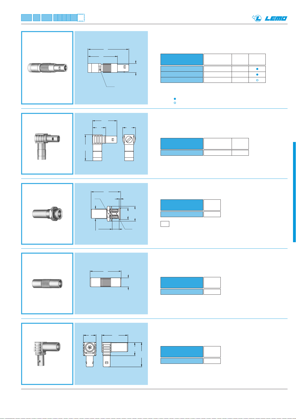
Note: Standard, first choice alternative
Non standard, on request only
19www.lemo.com
®
®
FRT Straight plug with resistor
Part number
FRT.00.250.NTA00
FRT.00.250.NTA50
FRT.00.250.NTA100
Resistor
Weight
Note
(g)
shorted 4.4
50 Ω 0.6W 4.4
100 Ω 0.4W 4.4
RAD Fixed coupler, nut fixing
Part number
RAD.00.250.NTM
Weight
(g)
3.8
Part number
RMA.00.250.NTM
Weight
(g)
2.7
Note: the first contact type mentioned (page 7) is always the contact
at the flange end.
P5
Panel cut-out (page 38)
9
9.5
17.5
18.5
FTR Elbow plug (90°) with socket
Part number
FTR.00.250.NTA
Weight
(g)
5.4
RMA Free coupler
FLR Elbow plug (90°) with resistor
Part number
FLR.00.250.NTA50
Resistor
Weight
(g)
50 Ω 0.6 W 5.6
29
21
ø 6.4
S 5.5
18.8
9.5
S 9
5.5 maxi
M7x0.5
17.5
ø 9
22
1
S 6.3
ø 8
ø 10.2
22
ø 6.4
Page 22
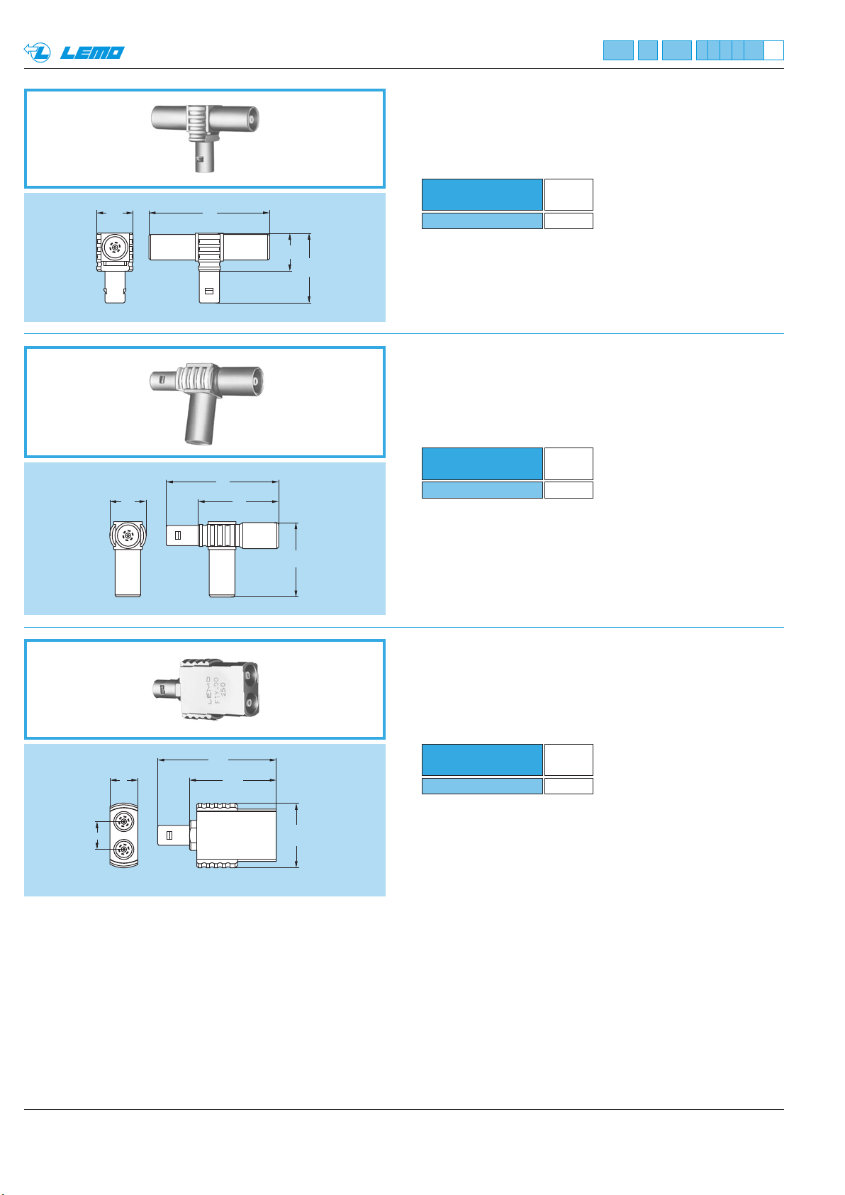
®
®
FTA T-plug with two sockets in line
ø 9
ø 9
Part number
30
9.5
17.5
FTA.00.250.NTF
Weight
(g)
7.8
FTL T-plug with two sockets (90°)
Part number
28
20
18.5
FTL.00.250.NTF
Weight
(g)
7.1
FTY Straight plug with two parallel sockets
29.5
7
21.5
Part number
FTY.00.250.NTF
Note: Test voltage: 1.1kV (rms) / IEC 60512-2 test 4a.
7
ø 16
Weight
(g)
12.5
20 www.lemo.com
Page 23
21www.lemo.com
®
®
Plastic housing models
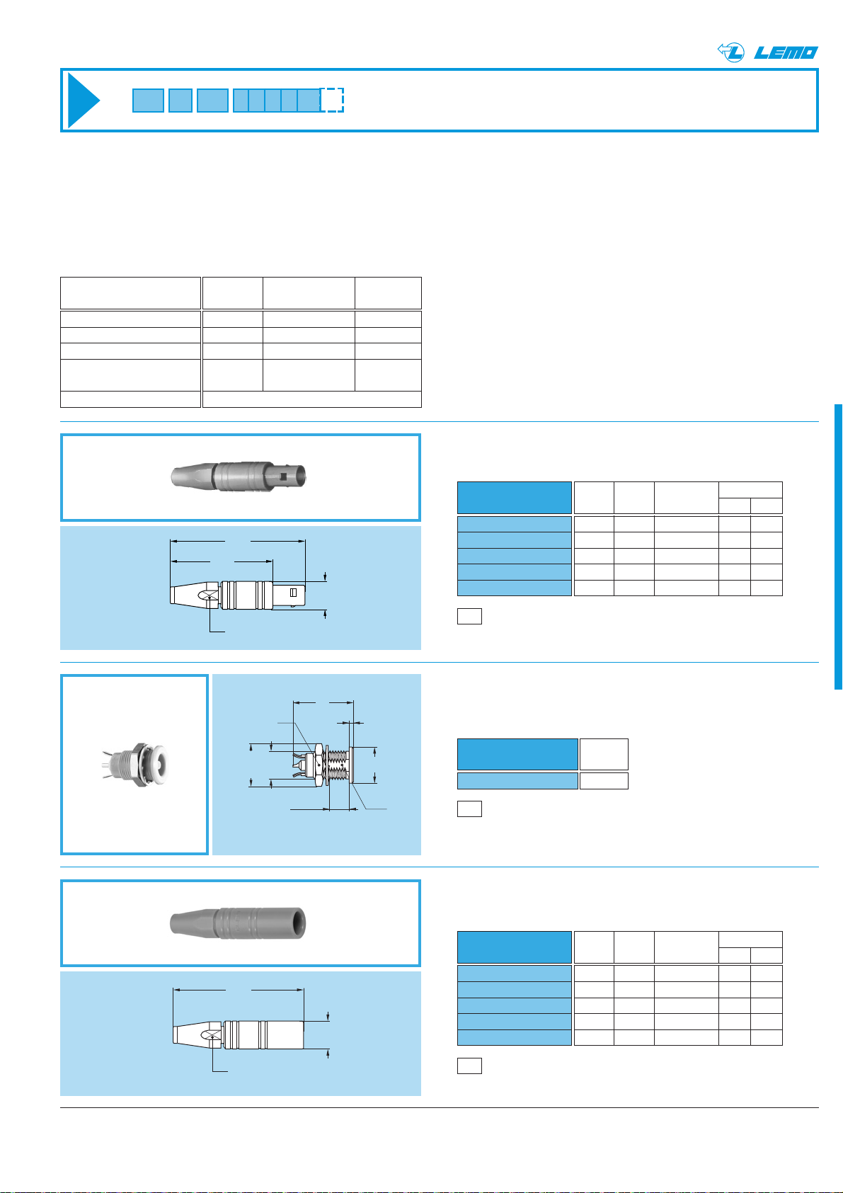
This plastic housing provides the ideal solution when the isolation of the connector is critical (non metallic). The FFA and
ERN models in PEEK allow weight saving and can provide ease of use in applications such as medical electronic instrumentation.
FFA.00.250.GTAC15
FFA.00.250.GTAC17
FFA.00.250.GTAC22
FFA.00.250.GTAC27
.FFA.00.250.GTAC31
M1
Cable assembly (page 39)
Part number
Cable Cond. Dielectric Ø Sheath Ø
group Ø max maxi mini maxi
9 0.55 1.45 1.1 1.4
– 0.55 1.45 1.3 1.7
1 0.55 1.95 1.7 2.1
2-3-4 0.55 1.95 2.3 2.7
8 0.55 1.95 2.8 3.0
~25.5
~33.5
S 6
ø7
FFA Straight plug with cable collet,
PEEK outer shell
PCA.00.250.GTLC15
PCA.00.250.GTLC17
PCA.00.250.GTLC22
PCA.00.250.GTLC27
PCA.00.250.GTLC31
M1
Cable assembly (page 39)
Part number
Cable Cond. Dielectric Ø Sheath Ø
group Ø max maxi mini maxi
9 0.55 1.45 1.1 1.4
– 0.55 1.45 1.3 1.7
1 0.55 1.95 1.7 2.1
2-3-4 0.55 1.95 2.3 2.7
8 0.55 1.95 2.8 3.0
PCA Free socket with cable collet,
PEEK outer shell
ERN Fixed socket, nut fixing,
with earthing tags,
PEEK outer shell
Part number
ERN.00.250.GTL
Weight
(g)
1.4
P5
Panel cut-out (page 38)
Characteristics
Value Standard Test
Contact retention force
Cable pull off force
Connector pull off force
Endurance
Operating temperature
> 18 N IEC 60512-8 15a
> 100 N IEC 60512-9 17a
> 90 N
> 5000
IEC 60512-5 9a
cycles
- 50°C + 250°C
Mechanical and climatical
Technical Characteristics
15
S 9
1
S 6
~32.5
ø 10.2
M7x0.5
5.5 maxi
S 6.3
ø 9
ø7
Page 24
22 www.lemo.com
®
®
HEP Fixed socket, nut fixing, watertight
for printed circuit (back panel mounting)
HGW Fixed socket, nut fixing, watertight
with rear sealing ring
Part number
HGW.00.250.NTLP
Weight
(g)
4.2
P1
Panel cut-out (page 38)
Part number
HEP.00.250.NTNP
Weight
(g)
7.4
HGP Fixed socket, nut fixing,
watertight or vacuumtight
Part number
HGP.00.250.NTLP
HGP.00.250.NTLPV
Weight
(g)
4.2
4.2
P1
Panel cut-out (page 38)
P5
Panel cut-out (page 38)
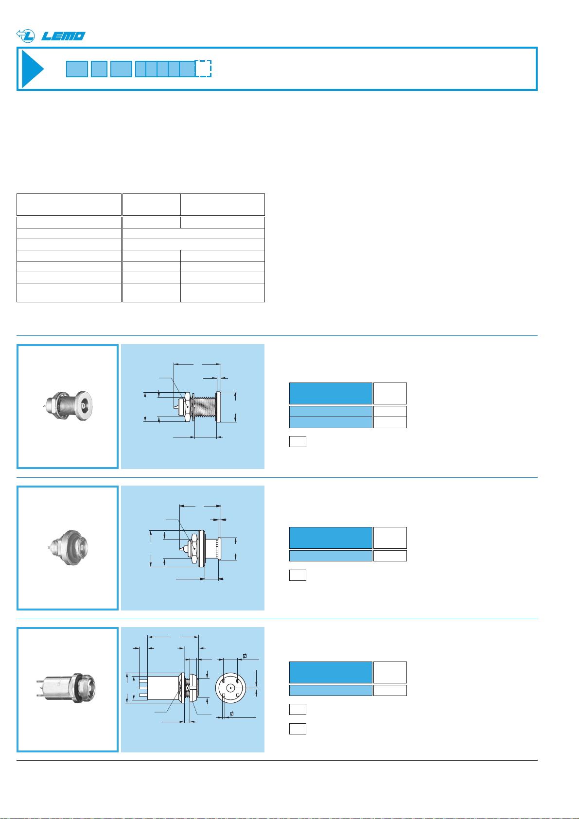
Watertight or vacuumtight models
Mechanical and climatical
A range of sealed sockets and couplers allows the device on which they are fitted to reach a protection index of IP68 as
per IEC 60529 (unmated). They are fully compatible with plugs of the same series and are widely used for portable
radios, military, laboratory equipment, aviation, etc.
These models are identified by a letter «P» at the end of the reference for watertight model and by a «PV» for vacuum tight models. Epoxy resin or o-rings are used to seal these models.
Characteristics Value Standard
> 5000 cycles IEC 60512-5 test 9a
up to 95% at 60° C
- 20° C/+100° C
> 144h IEC 60512-6 test 11f
20/80/21 IEC 60068-1
< 10
-7
mbar.l.s-1IEC 60512-7 test 14b
60 bars IEC 60512-7 test 14d
Endurance
Humidity
Temperature range
Salt spray corrosion test
Climatical category
Leakage rate (He)
1)
Maximum
operating pressure
2)
Note:
1)
only for vacuumtight models.
2)
this value corresponds to
the maximum allowed pressure
difference for the assembled
socket.
Note: Non standard, on request only
P15
PCB drilling pattern
(page 38)
17
1.5
ø 11
15
1
ø 10.2
S 9
M7x0.5
8 maxi
S 9
ø 13
M7x0.5
3.8 mini
5.8 maxi
ø 8
18
3
ø11
ø8.7
S 9
2 maxi
4.7
2.5
S 6.3
5.08
ø 0.7
M7x0.5
0.9 (4 x)
Page 25
®
S 9
ø 11
M7x0.5
®
EWF Fixed socket, nut fixing, watertight
or vacuumtight (back panel mounting)
17
3
S 9
9.5 maxi
M7x0.5
ø 10.2
Part number
EWF.00.250.NTLP
EWF.00.250.NTLPV
P1
Panel cut-out (page 38)
Weight
(g)
4.2
4.2
EWV Fixed socket, screw fixing, watertight
or vacuumtight
17
2.6
ø 11
ø 1.5
ø 7.9
Part number
EWV.00.250.NTLP
EWV.00.250.NTLPV
P2
Panel cut-out (page 38)
Weight
(g)
3.7
3.7
ø 11
ø 10.2
ø 7
S 9
5.5 maxi
M7x0.5
24.5
24.5
1.5 max
16.5
S 5
1.5
M7x 0.5
ø 11
ø 10
SWH Fixed coupler, nut fixing, vacuumtight
Part number
SWH.00.250.NTMV
P1
Panel cut-out (page 38)
Note: this model is sealed with o-rings (no epoxy).
Weight
(g)
5.2
VPS Fixed socket, short shell,
vacuumtight with cable crimping
(back panel mounting)
Cond. Ø Dielectric Ø Sheath Ø
Part number
VPS.00.250.CTLE31
P1
Panel cut-out (page 38)
Cable assembly, please contact customer service
Cable
group
mini maxi
maxi maxi
3-4 0.46 0.55 1.65 3.0
23www.lemo.com
Page 26
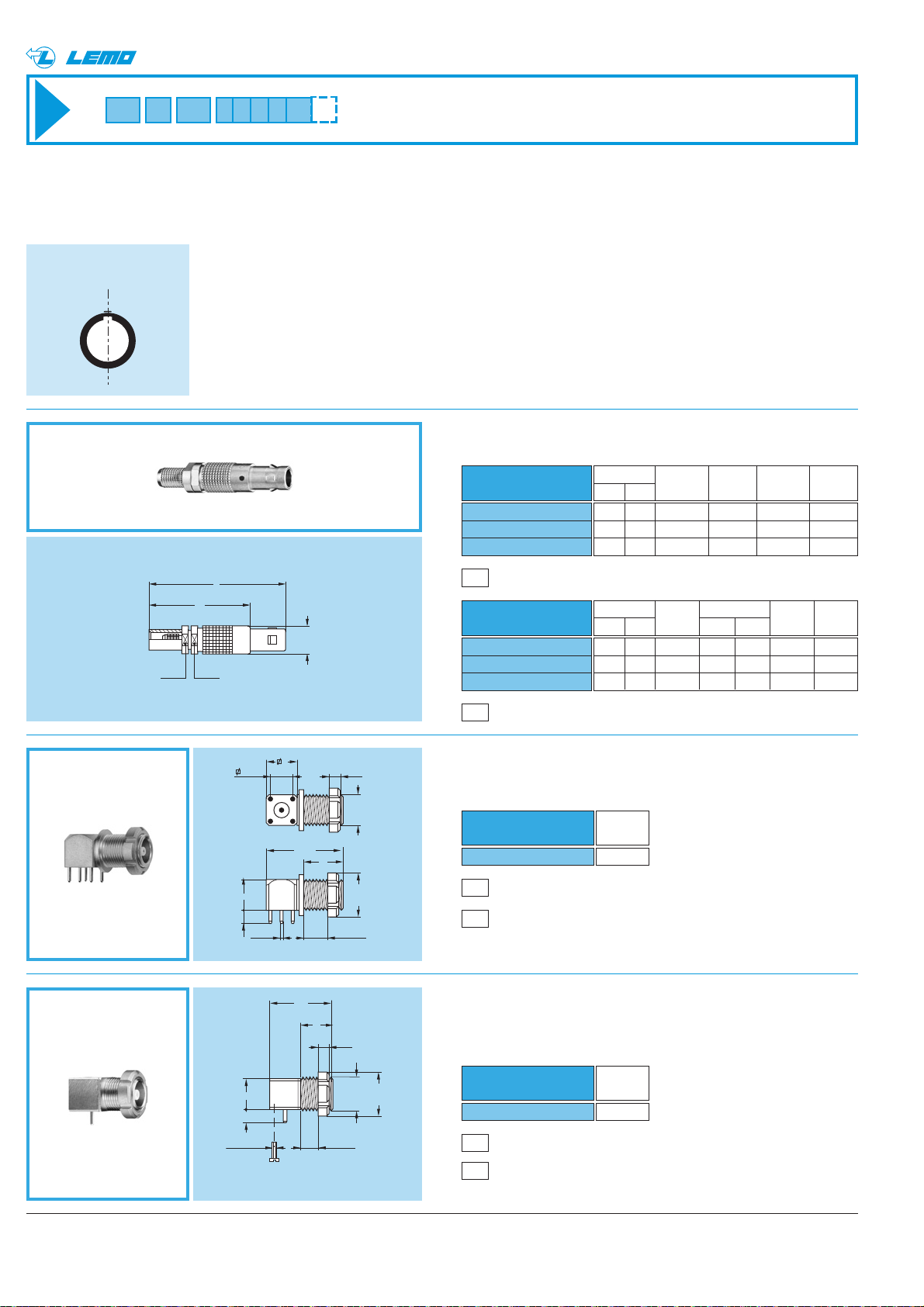
Metal housing models with mechanical keying
The straight plug and receptacle models FSG,XBG,XRG,XSG,ESG,EXG and PSG are available with a key to avoid cross
mating of similar connectors. These models are not included in the NIM-CAMAC standard.
The standard "G" key consists of one mechanical alignment key.
24 www.lemo.com
®
®
FSG Straight plug with key (G),
with cable crimping
XBG Elbow socket (90°) with slotted nut,
for printed circuit with key (G)
Part number
XBG.00.250.NTN
Weight
(g)
5.1
XRG Elbow socket (90°), with key (G), short shell
and slotted nut, for printed circuit,
screw fixing (back panel mounting)
Part number
XRG.00.250.NTN
Weight
(g)
3.8
P14
PCB drilling pattern
(page 38)
P1
Panel cut-out (page 38)
P1
Panel cut-out (page 38)
P12
PCB drilling pattern
(page 38)
Front view of the
standard "G" key
M4
Cable assembly, crimp contact (page 40)
M5
Cable assembly, solder contact (page 41)
Part number
FSG.00.250.NTCE24
FSG.00.250.NTCE31
FSG.00.250.NTCE52
Dim Cable Cond. Ø Dielec. Sheath
L M group mini maxi Ø maxi Ø maxi
31 23 1 0.28 0.4 0.95 2.35
31 23 3-4 0.46 0.55 1.65 3.0
34 26 6 0.90 0.97 3.05 5.2
Part number
FSG.00.250.NTAE24
FSG.00.250.NTAE31
FSG
.00.250.NTAE52
Dim Cable Cond. Dielec. Sheath
L M group Ø maxi Ø maxi Ø maxi
31 23 1 0.4 0.95 2.35
31 23 3-4 0.55 1.65 3.0
34 26 6 0.97 3.05 5.2
L
M
ø 6.4
S 5.5S 5.5
5.08
3
7
ø 0.7
(5 x)
7
17.5
2.5
M7x0.5
9
ø 10
5 maxi
14
7
2.5
73
2 x M 1.4
4 maxi
M7x0.5
ø 10
Page 27
25www.lemo.com
®
®
P1
Panel cut-out (page 38)
P15
PCB drilling pattern
(page 38)
P1
Panel cut-out (page 38)
Part number
XSG.00.250.NTN
Weight
(g)
5.4
P1
Panel cut-out (page 38)
P12
PCB drilling pattern
(page 38)
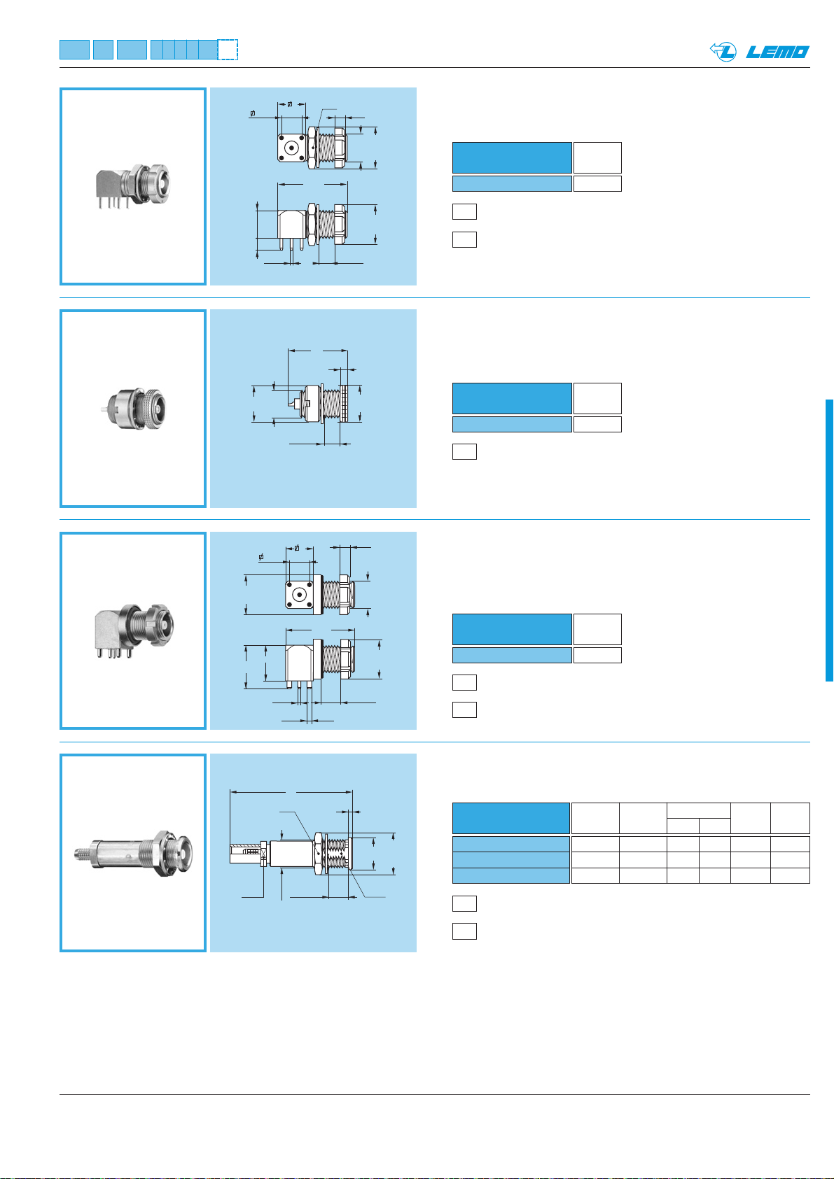
XSG Elbow socket (90°) with slotted with key (G),
and hex nuts for printed circuit
ESG Fixed socket with two round nuts,
threaded shell, with key (G)
(back panel mounting)
Part number
ESG.00.250.NLL
Weight
(g)
3.1
EXG Elbow socket (90°) with slotted nut for printed
circuit, with key (G), with o-ring on flange
(back panel mounting). Special shell design.
Part number
EXG.00.250.NTNY
Weight
(g)
6.3
PSG Fixed socket, nut fixing, with key (G)
with cable crimping
M4
Cable assembly, crimp contact (page 40)
P5
Panel cut-out (page 38)
Part number
PSG.00.250.NTME24
PSG.00.250.NTME31
PSG.00.250.NTME52
Dim Cable Cond. Ø Dielec. Sheath
L group mini maxi Ø maxi Ø maxi
30 1 0.28 0.4 0.95 2.35
30 3-4 0.46 0.55 1.65 3.0
33 6 0.90 0.97 3.05 5.2
5.08
7
3
ø 9
ø 0.7
(5 x)
7
M7x0.5
4 maxi
17.5
S 9
4 maxi
2.5
ø 10.3
M7x0.5
ø 10
15
2
ø 9
ø10
11
S 5.5
5.08
9
ø 0.7
ø 1.2 (4x)
L
S 9
M7x0.5
7
5.5 maxi
17.5
2.5
M7x0.5
5 maxi
ø 10
1
ø 8
ø 10.2
S 6.3
Page 28
26 www.lemo.com
®
®
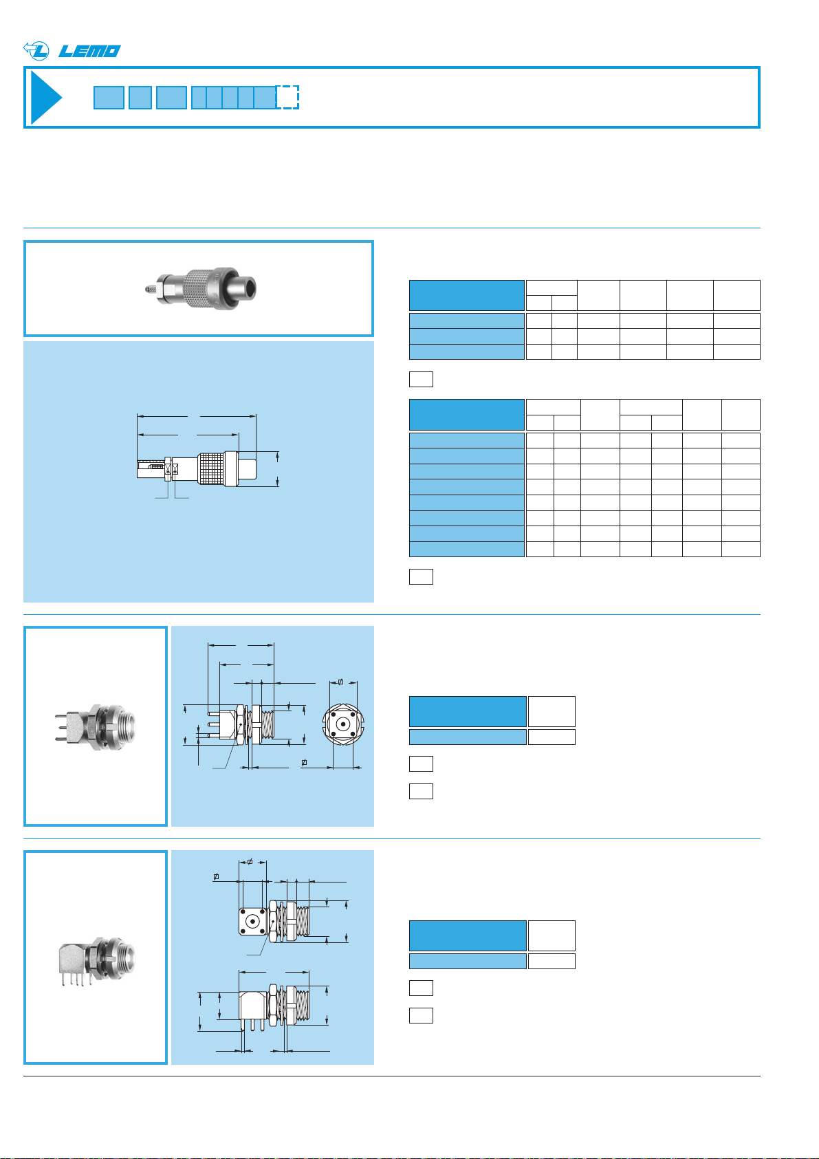
EPE Straight socket with two nuts,
for printed circuit
Part number
EPE.00.250.NTN
Weight
(g)
4.3
Threaded-coupling models
The straight plug and receptacle models FVS, EPE and EPS are available with threaded coupling.
On sockets, 3.2 mm minimum length of free threading must be available to ensure screw mating. These models are not
included in the NIM-CAMAC standard.
FVS Straight plug for cable crimping
M4
Cable assembly, crimp contact (page 40)
M5
Cable assembly, solder contact (page 41)
Part number
FVS.00.250.NTCE24
FVS.00.250.NTCE25
FVS.00.250.NTCE30
FVS.00.250.NTCE31
FVS.00.250.NTCE35
FVS.00.250.NTCE44
FVS.00.250.NTCE52
FVS.00.250.NTCE56
Dim Cable Cond. Ø Dielec. Sheath
L M group mini maxi Ø maxi Ø maxi
31 23 1 0.28 0.4 0.95 2.35
31 23 1 0.28 0.4 1.15 2.35
31 23 2 0.28 0.4 1.65 3.0
31 23 3-4 0.46 0.55 1.65 3.0
31 23 8 0.46 0.55 1.65 3.35
31 23 5 0.28 0.4 2.65 4.35
34 26 6 0.90 0.97 3.05 5.2
34 26 7 0.90 0.97 3.05 5.45
Part number
FVS.00.250.NTAE24
FVS.00.250.NTAE31
FVS.00.250.NTAE52
Dim Cable Cond. Dielec. Sheath
L M group Ø maxi Ø maxi Ø maxi
31 23 1 0.4 0.95 2.35
31 23 3-4 0.55 1.65 3.0
34 26 6 0.97 3.05 5.2
P1
Panel cut-out (page 38)
P12
PCB drilling pattern
(page 38)
EPS Elbow socket (90°) with two nuts,
for printed circuit
Part number
EPS.00.250.NTN
Weight
(g)
5.4
P1
Panel cut-out (page 38)
P12
PCB drilling pattern
(page 38)
L
M
ø 9
S5S5
17
14
2.5 3.2 mini
7
ø10.2
S 9
ø 0.7
(5x)
10
ø 0.7
(5 x)
0.7 maxi
7
5.08
S 9
7
M7x0.5
2.5 3.2 mini
17.5
ø 10
5.08
0.7 maxi
M7x0.5
ø 10
ø 10.2
Page 29
27www.lemo.com
®
®
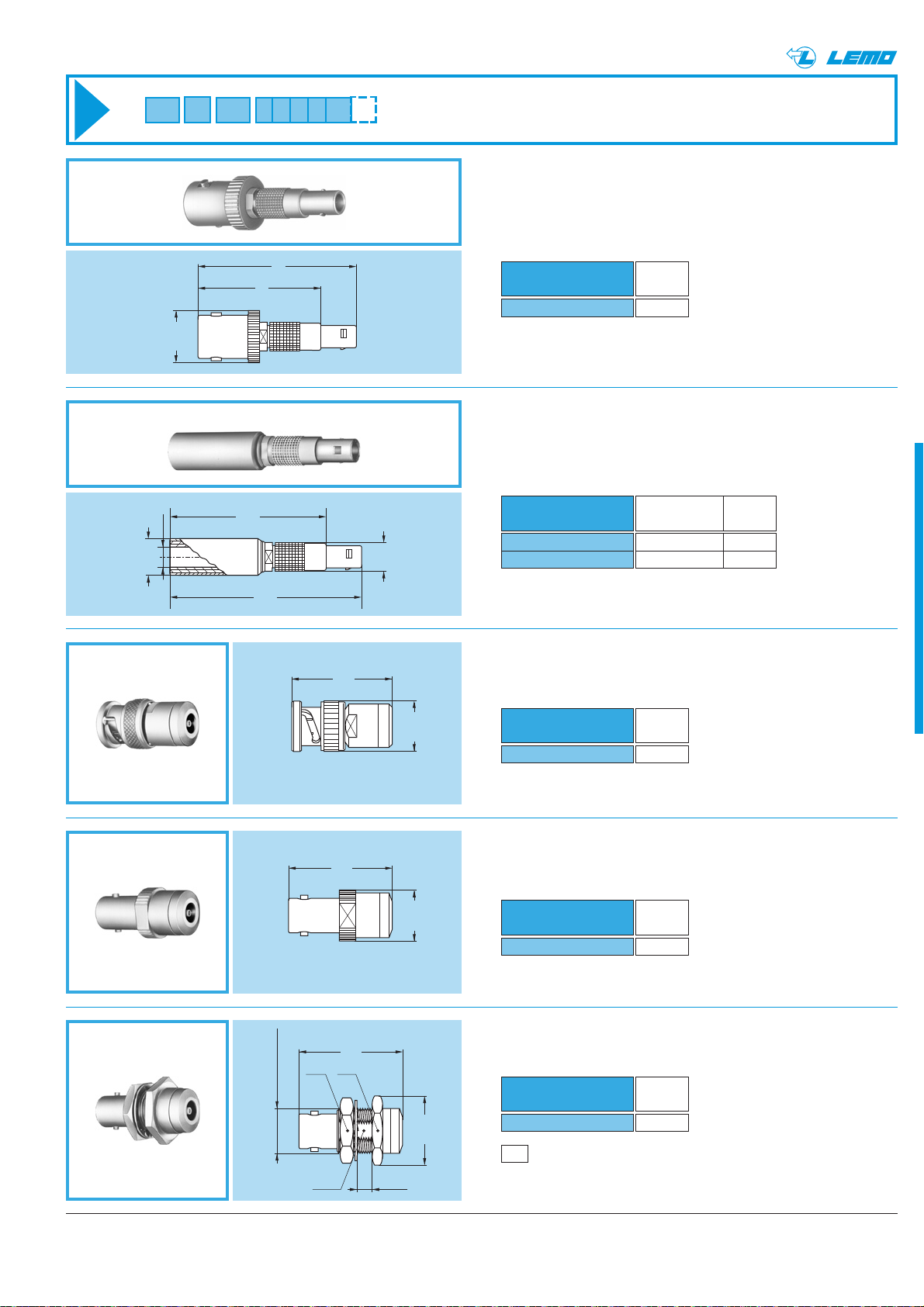
ABA Adaptor from LEMO socket to BNC plug
ABC Adaptor from LEMO socket
to BNC socket
Part number
ABA.00.250.NTL
Weight
(g)
18.7
Part number
ABC.00.250.NTM
Weight
(g)
17
ABF Adaptor from LEMO plug to BNC socket
APF Adaptor from LEMO plug
to CINCH socket
Part number
ABF.00.250.NTA
Weight
(g)
8.3
Part number
APF.00.250.DTAB
APF.00.250.DTAR
Colour Weight
of the ring (g)
white 7
red 7
Adaptors
ABD Adaptor from LEMO socket
to BNC fixed socket
Part number
ABD.00.250.NTM
Weight
(g)
21.4
P7
Panel cut-out (page 38)
ø 4.6
ø 8.3
ø 11.5
35.5
28
43.5
36
ø 6.4
28.5
29.5
S 16 S 17
1/2-28 UNEF - 2A
29.5
ø 14.5
ø 14.5
ø 19.5
S 11.7
5 maxi
Page 30
28 www.lemo.com
®
®
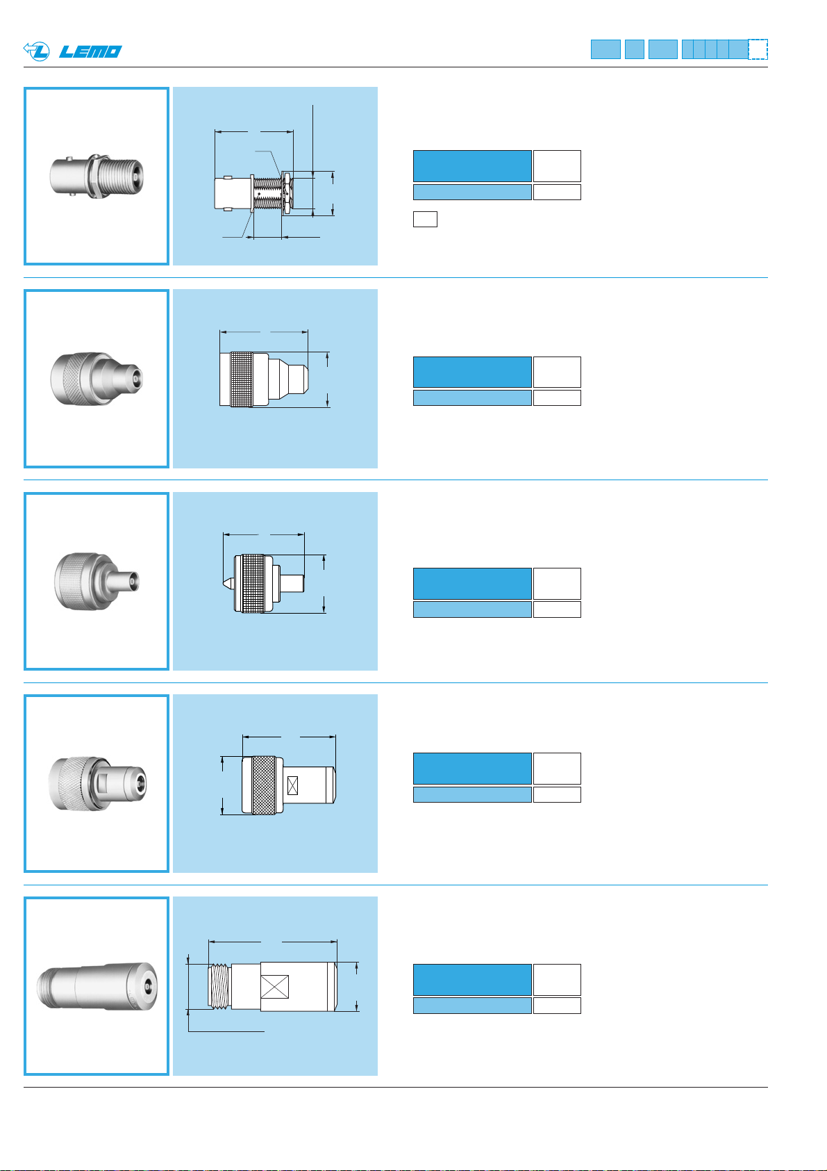
AGH Adaptor from LEMO socket to UHF plug
26
ø 18.5
ANA Adaptor from LEMO socket to N plug
33.5
ø 20.5
ANB Adaptor from LEMO socket to N socket
Part number
AGH.00.250.NTL
Weight
(g)
13.8
Part number
ANA.00.250.NTL
Weight
(g)
38
ABB Adaptor from LEMO fixed socket
to BNC socket
Part number
ABB.00.250.NTM
Weight
(g)
9.4
P6
Panel cut-out (page 38)
ACA Adaptor from LEMO socket to C plug
Part number
ACA.00.250.NTL
Weight
(g)
32
Note: Non standard, on request only
Part number
ANB.00.250.NTM
Weight
(g)
61.7
Note: Non standard, on request only
25
S 11
S 8.7
3/8-32 UNEF - 2A
9.5 maxi
ø 14
31
ø 19.5
45.5
ø 17.5
5/8 - 24 UNEF - 2A
Page 31
29www.lemo.com
®
P8
Panel cut-out (page 38)
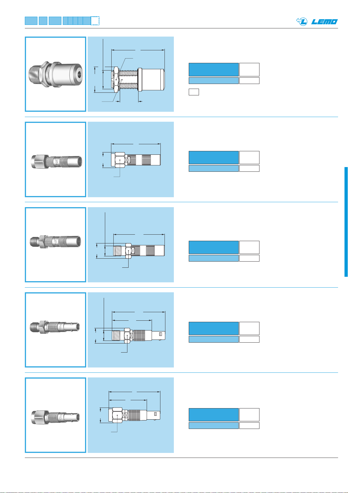
ANC Adaptor from LEMO socket
to N fixed socket
S 19
ASA Adaptor from LEMO socket to SMA plug
Part number
ASA.00.250.NTL
Weight
(g)
4.9
Part number
ASB.00.250.NTM
Weight
(g)
4.6
Part number
ASF.00.250.NTA
Weight
(g)
4.6
ASB Adaptor from LEMO socket
to SMA socket
ASF Adaptor from LEMO plug to SMA socket
Part number
ANC.00.250.NTM
Weight
(g)
63.5
Note: Non standard, on request only
Part number
ASG.00.250.NTC
Weight
(g)
4.9
ASG Adaptor from LEMO plug to SMA plug
®
46
5/8 - 24 UNEF - 2A
ø 21.8
S 13.5
ø 9
S 8
1 / 4 - 36 UNS - 2A
ø 9
17 maxi
S 8
30
30.8
1 / 4 - 36 UNS - 2A
ø 9
ø 9
S 8
S 8
31.8
23.8
31
23
Page 32
30 www.lemo.com
®
®
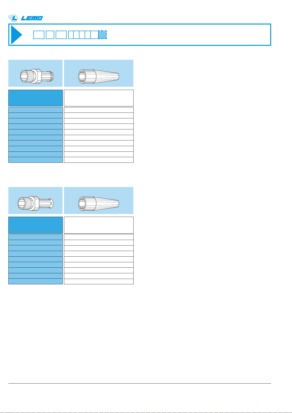
Need to be
ordered separately
(see page 33)
Reference
Variant
GMA.00.0●●.D●
GMA.00.0●●.D●
–
GMD or GMB.00.0●●.D●
GMD or GMB.00.0●●.D●
GMA.0B.0●●.D●
GMA.0B.0●●.D●
GMA.0B.0●●.D●
GMA.0B.0●●.D●
GMA.0B.0●●.D●
C15Z
C17Z
C22Z
C27Z
C31Z
C52Z
K37Z
K42Z
D42Z
D52Z
Bend relief for models with collet (letter Z in the variant position)
Bend relief for models for cable crimping (no letter in the variant position)
The bend relief can be fitted directly over the crimp ferrule
Need to be ordered
Need to be
ordered separately
(see page 33)
Reference
GMD or GMB.00.0●●.D●
GMD or GMB.00.0●●.D●
GMD or GMB.00.0●●.D●
GMD or GMB.00.0●●.D●
GMD or GMB.00.0●●.D●
–
–
–
–
E24
E25
E30
E31
E32
E35
E44
E52
E56
Need to be ordered
Note: The “GMD” are thin bend reliefs (for very flexible cables)
Note: The “GMD” are thin bend reliefs (for very flexible cables)
Page 33
31www.lemo.com
®
FRT
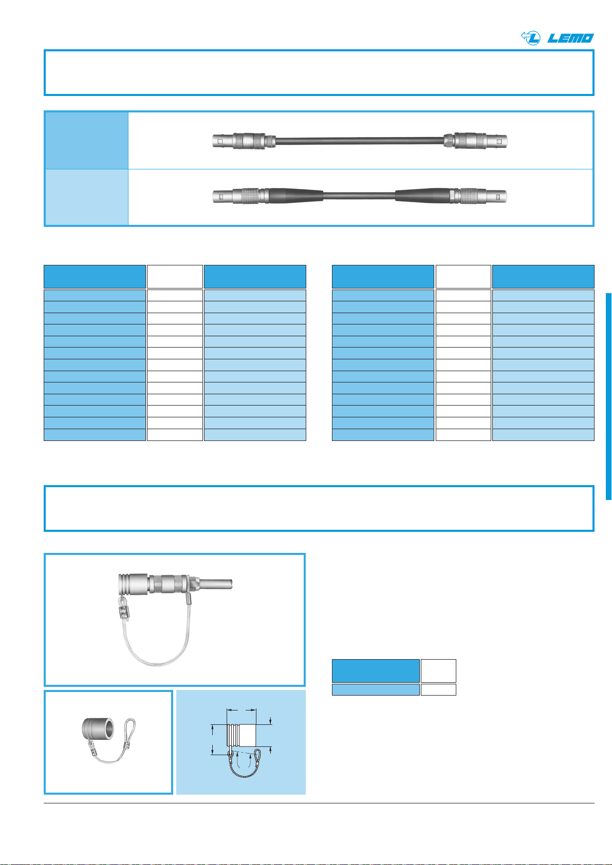
Assembled cables
MFB models
MSB models
Delay lines Assembled Cables
Part number
Delay
(ns)
0.5
1.0
2.0
3.0
4.0
5.0
6.0
8.0
10.0
16.0
20.0
32.0
64.0
MFB.00.250.RTE005
MFB.00.250.RTE010
MFB.00.250.RTE020
MFB.00.250.RTE030
MFB.00.250.RTE040
MFB.00.250.RTE050
MFB.00.250.RTE060
MFB.00.250.RTE080
MFB.00.250.RTE100
MFB.00.250.RTE160
MFB.00.250.RTE200
MFB.00.250.RTE320
MFB.00.250.RTE640
Part number
MSB.00.250.RTE005
MSB.00.250.RTE010
MSB.00.250.RTE020
MSB.00.250.RTE030
MSB.00.250.RTE040
MSB.00.250.RTE050
MSB.00.250.RTE060
MSB.00.250.RTE080
MSB.00.250.RTE100
MSB.00.250.RTE160
MSB.00.250.RTE200
MSB.00.250.RTE320
MSB.00.250.RTE640
Part number
Length
(cm)
10
20
30
40
50
60
80
100
150
200
300
400
500
MFB.00.250.LTE010
MFB.00.250.LTE020
MFB.00.250.LTE030
MFB.00.250.LTE040
MFB.00.250.LTE050
MFB.00.250.LTE060
MFB.00.250.LTE080
MFB.00.250.LTE100
MFB.00.250.LTE150
MFB.00.250.LTE200
MFB.00.250.LTE300
MFB.00.250.LTE400
MFB.00.250.LTE500
Part number
MSB.00.250.LTE010
MSB.00.250.LTE020
MSB.00.250.LTE030
MSB.00.250.LTE040
MSB.00.250.LTE050
MSB.00.250.LTE060
MSB.00.250.LTE080
MSB.00.250.LTE100
MSB.00.250.LTE150
MSB.00.250.LTE200
MSB.00.250.LTE300
MSB.00.250.LTE400
MSB.00.250.LTE500
Note: the standard cable used to manufacture these cable assemblies is according to IEC.50.2.1 standard. On request this type of cable can be
replaced by other coaxial cables. Other cable lengths are available on request.
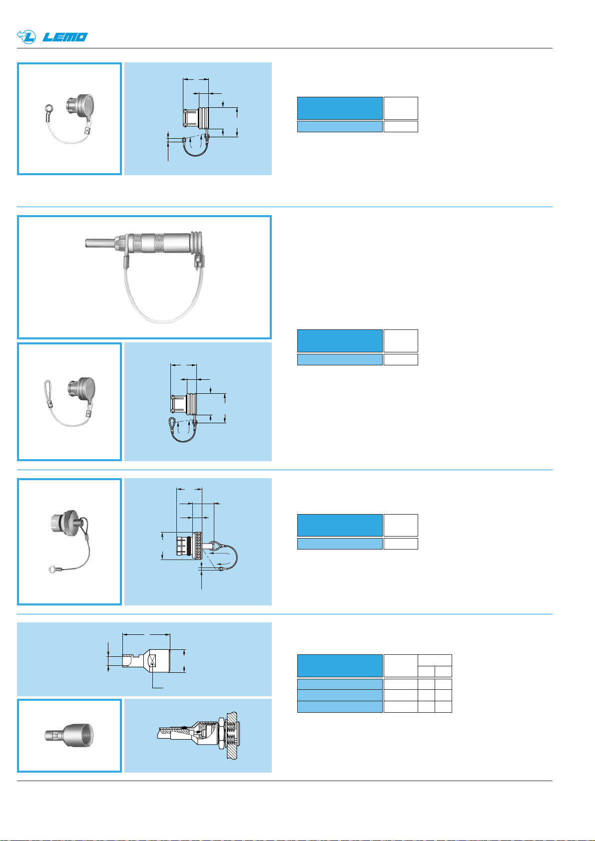
Accessories
Caps for plug with or without keying
Part number
BFG.00.100.PCSG
Weight
(g)
0.7
Note: upon request this cap can be supplied in black and the last
letter “G” of the part number should be replaced with “N”.
Fitting of the cord
Slide the plug into the loop of the cord. Place the loop
into the groove in front of the collet nut and tighten the
loop.
BFG
● Body material: Polyoxymethylen (POM) grey
● Cord material: Polyamid 6, grey
● O-ring material: Silicone rubber
● Maximum operating temperature: 100°C
● Watertightness: IP61 according to IEC 60529
®
10
9.8
ø 7.5
60
Page 34
32 www.lemo.com
®
®
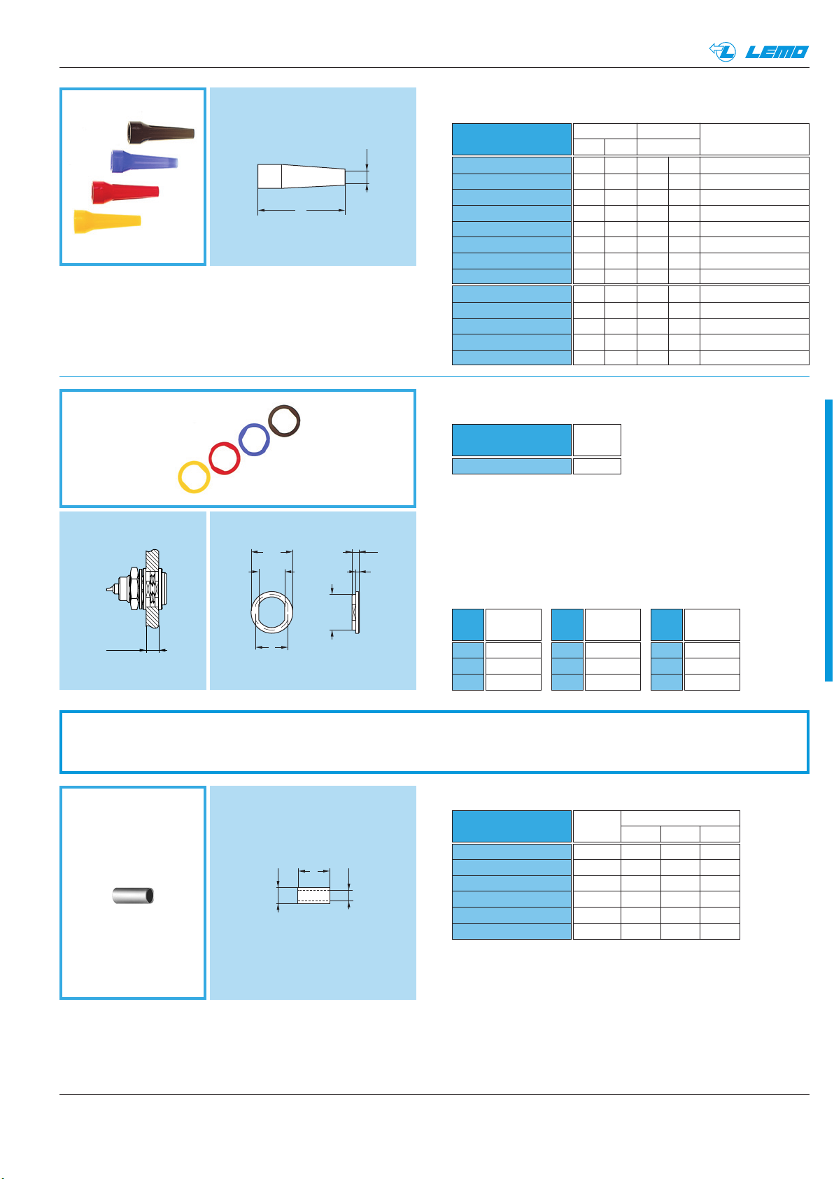
Blanking cap for fixed socket and free
straight socket
9.8
9
ø 7.5
ø 3.5
60
3.5
Part number
BRA.00.200.PCSG
Weight
(g)
0.6
Note: upon request this cap can be supplied in black and the last letter
“G” of the part number should be replaced with “N”.
Fitting of the cord
Slide the socket into the loop of the cord. Place the loop into
the groove in front of the collet nut and tighten the loop.
● Body material: Polyoxymethylen (POM) grey
● Cord material: Polyamid 6, grey
BRA
● O-ring material: Silicone rubber
● Maximum operating temperature: 100°C
● Watertightness: IP61 according to IEC 60529
Blanking cap for free socket
60
9.8
9
ø 7.5
3.5
Note: upon request this cap can be supplied in black and the last letter
“G” of the part number should be replaced with “N”.
BRD
● Body material: Polyoxymethylen (POM) grey
● Cord material: Polyamid 6, grey
● O-ring material: Silicone rubber
● Maximum operating temperature: 100°C
● Watertightness: IP61 according to IEC 60529
Blanking cap for fixed socket,
free socket and coupler
BRE
● Body material: Brass (UNS C 38500), nickel-plated (3 µm)
● Cable material: Stainless steel
● O-ring material: Silicone rubber or FPM
● Maximum operating temperature: 250°C
● Watertightness: IP61 according to IEC 60529
Earthing cap
Part number
Cable
group
Dim.
LC
Note: the shield braid of the cable should be soldered onto the back
of the cap screwed on the socket outer shell.
GCD
● Material: Brass (UNS C 38500) gold-plated (0.5 µm)
L
ø 8
S 7
ø C
Part number
BRD.00.200.PCSG
Weight
(g)
0.5
Part number
BRE.00.200.NAS
Weight
(g)
6.5
GCD.00.020.LA
GCD.00.032.LA
GCD.00.050.LA
1122.0
2-3-4 16 3.2
6195.0
ø 8
7.5
3.5
8.8
ø 3.5
60
Page 35
®
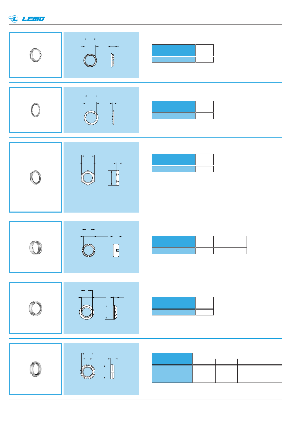
GM
3.5 maxi
Bend relief
•
®
L
Note:
a) for use with crimp models and nut for fitting a bend relief.
b) the last letter of the part number “•” specifies the colour.
Refer to the table below, for GRA washers, to define another
colour and replace the letter “•” by the one corresponding
to the colour required.
c) material: TPU (Thermoplastic Polyurethane)
d) operating temperature: -40°C + 80°C
ø10
6.4
ø A
1.8
1
Part number
GMA.00.012.D
GMA.00.018.D
GMB.00.025.D
GMB.00.028.D
GMB.00.032.D
GMD.00.025.D
GMD.00.028.D
GMD.00.032.D
GMA.0B.025.D
GMA.0B.030.D
GMA.0B.035.D
GMA.0B.040.D
GMA.0B.045.D
Insulating washers
GRA
Part number
GRA.00.269.G
•
Dim. ø Cable
A L max min
•
•
•
•
•
•
•
•
•
•
•
•
•
1.2 22 1.4 1.1 FFM.00.130.LN
1.8 22 2.1 1.8 FFM.00.130.LN
2.5 22 2.8 2.5 FFM.00.130.LN
2.8 22 3.1 2.8 FFM.00.130.LN
3.2 22 3.5 3.2 FFM.00.130.LN
2.5 22 2.8 2.5 FFM.00.130.LN
2.8 22 3.1 2.8 FFM.00.130.LN
3.2 22 3.5 3.2 FFM.00.130.LN
2.5 24 2.9 2.5 FFM.0B.130.LC
3.0 24 3.4 3.0 FFM.0B.130.LC
3.5 24 3.9 3.5 FFM.0B.130.LC
4.0 24 4.4 4.0 FFM.0B.130.LC
4.5 24 5.2 4.5 FFM.0B.130.LC
Weight
(g)
0.1
Nut for fitting the
bend relief part nb
Note:
a) sockets and plugs mounted on panels can be fitted with insulating
washers. The nine colours available combined with those for the
bend reliefs makes colour coding possible.
b) the last letter of the part number “•” specifies the colour.
Refer to the table below to define another colour and replace
the letter “•” by the one corresponding to the colour required.
c) material: Polyamid
d) operating temperature: -40°C + 80°C
8
L
ø A
● Material: Copper (UNS C 18700) nickel-plated (3µm)
ø 8.8
Spare Parts
ø B
Ref.
Colour
A
blue
B
white
G
grey
FFS
Crimp ferrule
Part number
FFS.00.160.DN
FFS.00.161.MN
FFS.00.162.DN
FFS.00.163.DN
FFS.00.164.DN
CRK.0A.160.DN
Ref.
J
M
N
Colour
yellow
brown
black
Cable
group
Ref.
R
S
V
Dim.
øA ø B L
1 3.1 2.4 8
2-3-4 3.8 3.05 8
8 4.4 3.4 8
5 5.3 4.4 8
6 6.2 5.25 11
7 6.2 5.5 11
Colour
red
orange
green
Note: sockets and plugs to be crimped are always supplied with a
crimp ferrule. To order this accessory separately, use the above part
numbers.
33www.lemo.com
Page 36
34 www.lemo.com
®
®
GBB Tapered washer
ø 9
2
ø 7.1
GEA Hexagonal nut
GEB Round nut
M7 x 0.5
4
ø 9
GEC Conical nut
8
M7 x 0.5
2.5
ø 10
GEG Notched nut
Part number
GBB.00.250.LN
Weight
(g)
0.2
Part number
GEA.00.240.LN
Weight
(g)
0.6
Part number
GEC.00.240.LN
Weight
(g)
0.6
Part number
GEB.00.240.LN
Weight Standard
(g) for models
0.8 ECP, ESG
● Material: Brass (UNS C 38500) nickel-plated (3 µm)
● Material:
- Brass (UNS C 38500) nickel-plated (3 µm)
- Aluminium alloy natural anodized
● Material: Brass (UNS C 38500) nickel-plated (3 µm)
● Material: Brass (UNS C 38500) nickel-plated (3 µm)
● Material: Brass (UNS C 38500) nicked-plated (3 µm)
Note: to order this accessory separately, use the above part number.
Note: sockets and plugs are supplied with a hexagonal nut as stan-
dard. To order this accessory separately, use the above part number.
The last letters “LN” of the part number refer to the nut material and
treatment. If a nut in aluminium alloy is desired, replace the last letters
of the part number by “PT”.
Note: to order this accessory separately, use the above part number.
Note: to order this accessory separately, use the above part number.
Note: to order this accessory separately, use the above part numbers.
Dimensions (mm)
Standard
AB e L
for models
Part number
GEG.00.240.LN
EPE, EPS, EPR
8.7 10 M7 x 0.5 2.5 PES, PFS, PLK,
VPS, HEP
ø7.1
1
ø9.5
Part number
GBA.00.250.FN
Weight
(g)
0.2
Locking washerGBA
Note: sockets and plugs are always supplied with a locking washer.
To order this accessory separately, use the above part number.
9
M7 x 0.5
2
ø 10.2
ø A
e
ø B
L
Page 37
35www.lemo.com
®
®
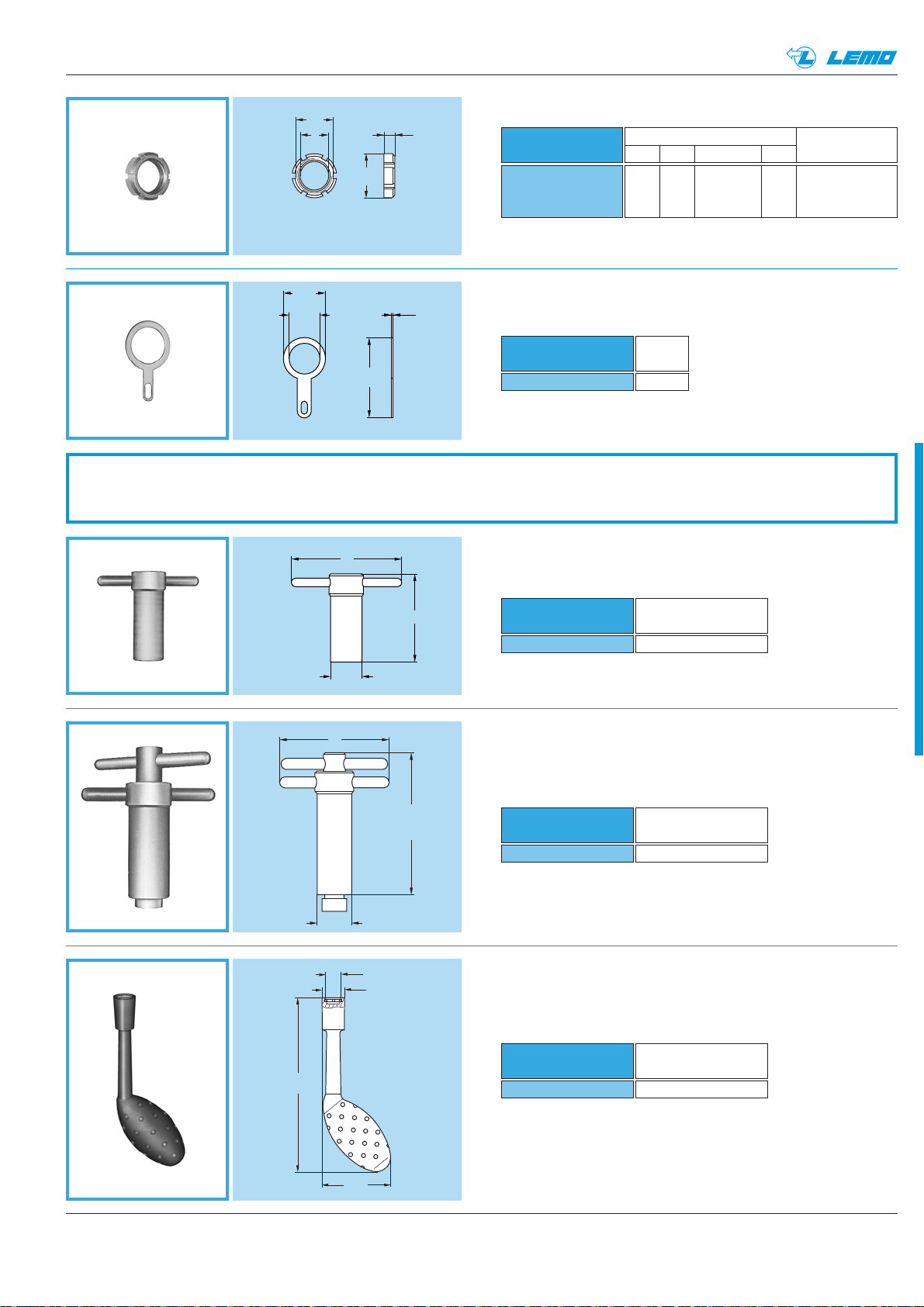
Tooling
50
40
ø 14
Part number
DCG.91.149.0TN
Part number
of the nut
GEA.00.240.LN
Spanner for hexagonal nutDCG
Part number
DCA.91.149.0TN
Part number
of the nut
GEA.00.240.LN
Spanner for hexagonal nut with locator
for flats on socket thread
DCA
Part number
DCH.91.101.PA
Part number
of the nut
GEG.00.240.LN
Spanner for notched nutDCH
● Material: Blackened steel
● Material: Blackened steel
● Material: blue polyurethane
GCA Earthing Washer
ø 9.5
0.4
18.2
ø 7.1
Part number
GCA.00.255.LT
Weight
(g)
0.2
● Material: Brass (UNS C 27400) treated CuSnZn (2 µm)
GEB Slotted nut
● Material: Brass (UNS C 38500) nicked-plated (3 µm)
Note: to order this accessory separately, use the above part numbers.
Dimensions (mm)
Standard
AB e L
for models
Part number
GEB.00.242.LN
ELF, XBG,
8.5 10 M7 x 0.5 2.5 XRG, XSG,
EXG
ø A
ø B
L
e
124
50
ø 14
ø 10.1
ø 12.8
65 maxi
48.3
Page 38
36 www.lemo.com
®
®
Part number
DCP.99.045.TC
DCP.99.050.TC
DCP.99.055.TC
DCP.99.060.TC
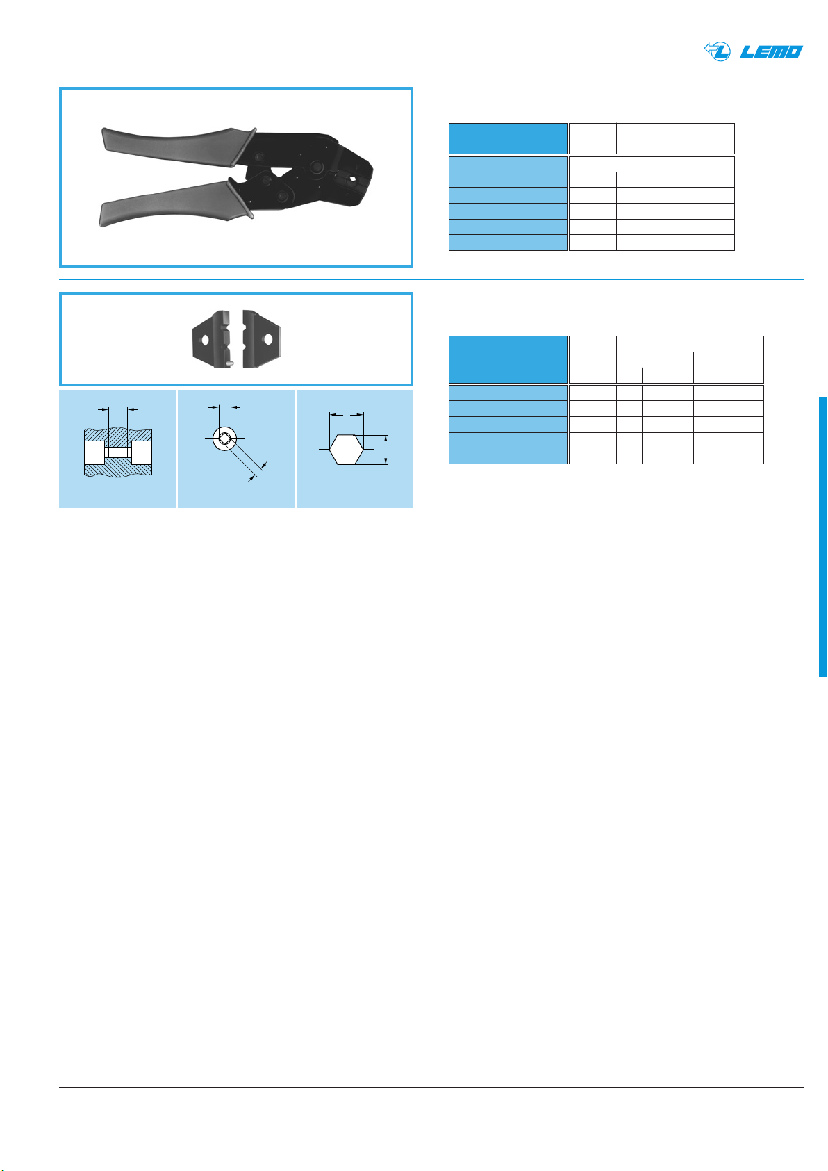
Dimensions
LMNS1
70 2 10.5 4.5
78 2 12.6 5.0
78 2 12.6 5.5
78 2 12.6 6.0
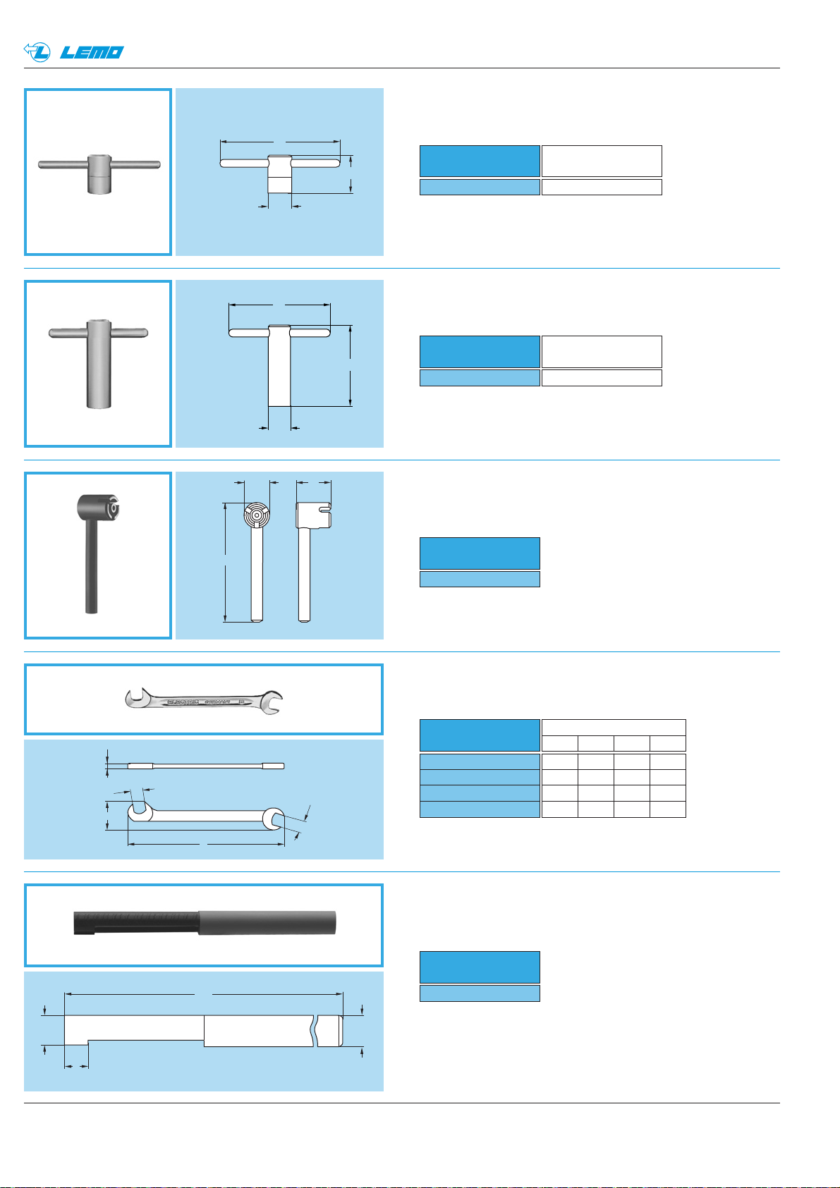
Flat spanner for collet nutDCP
Part number
DCR.91.106.0PN
Extraction tool for plugsDCR
● Material: Chrome-plated steel
Note: this type of tool has been produced in order to facilitate the
mating and unmating of plugs and is particularly useful in high density
applications.
● Material: Black Polypropylene
Part number
DCN.91.905.0TK
Spanner for assembling plug with 3 latchesDCN
● Material: Blackened steel
Part number
of the nut
GEB.00.240.LN
50
40
ø 11
Part number
DCB.91.119.0TN
Spanner for round nutDCB
● Material: Blackened steel
Part number
of the nut
GEB.00.242.LN
Part number
DCB.91.455.0LN
Spanner for slotted nutDCB
● Material: Steel, nicked plated
ø 9
60
ø 11
19
12
42
M
S1
N
L
S1
ø 10.3
120
9
ø 12
Page 39
®
®
L
A
B
A
B
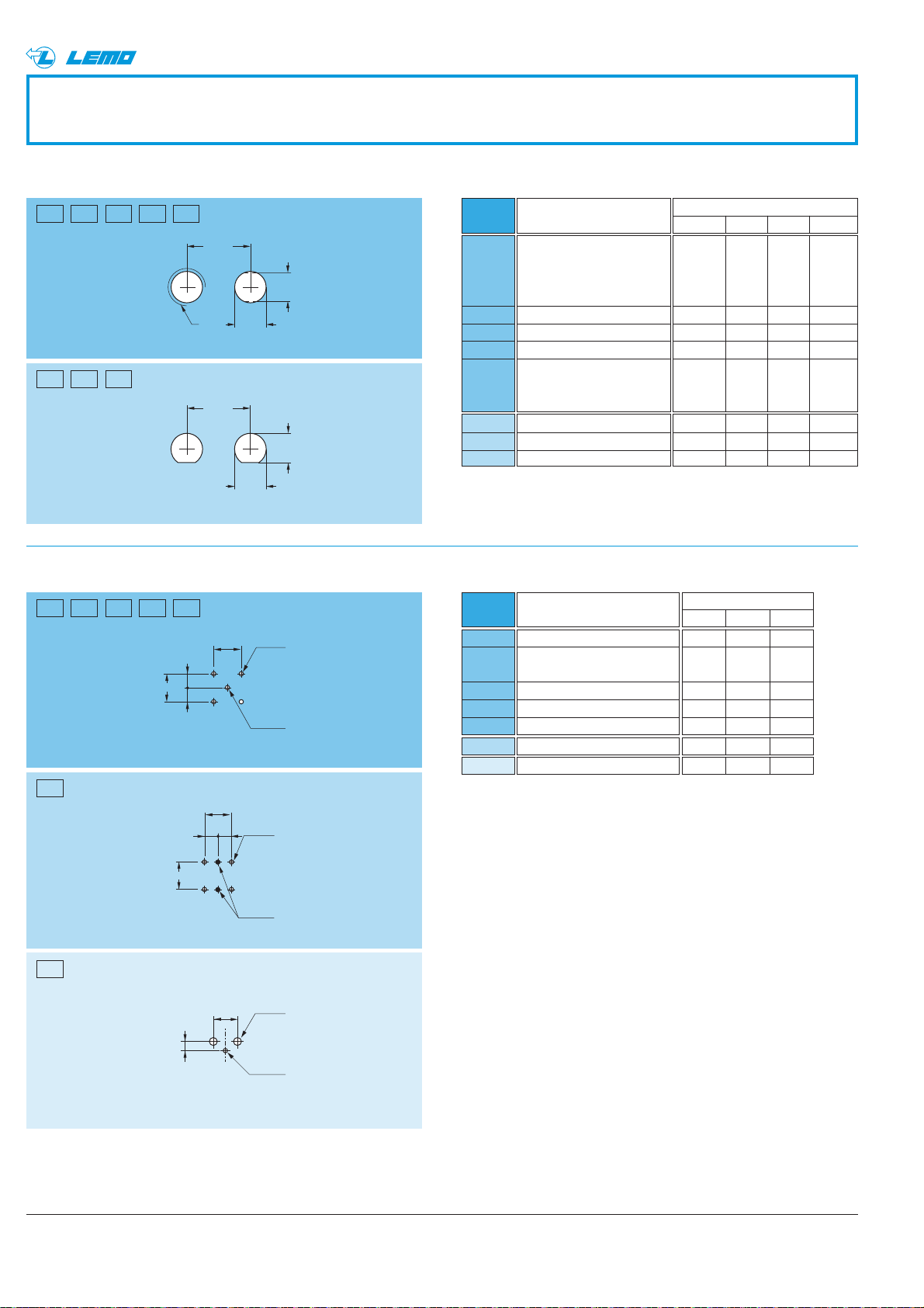
Crimping tool with dieDPE
for contacts for shield
Part number
DPE.99.000.00
DPE.99.123.1K
DPE.99.123.8K
DPE.99.124.3K
DPE.99.125.2K
DPE.99.176.2K
Dies
DPN
Part number
DPN.99.123.1K
DPN.99.123.8K
DPN.99.124.3K
DPN.99.125.2K
DPN.99.176.2K
Cable Crimp collet
group ref.
Crimping tool with no die
1 E24
2-3-4 E30, E31
8 E35
5 E44
6-7 E52, E56
Die dimension
Cable
For contacts For shield
group
A B L A B
1 1.29 0.91 2.0 3.10 2.70
2-3-4 1.29 0.91 2.0 3.80 3.30
8 1.29 0.91 2.0 4.36 3.78
5 1.29 0.91 2.0 5.20 4.50
6-7 1.71 1.21 2.5 6.20 5.37
● Dies material: Blackened steel
37www.lemo.com
Page 40
38 www.lemo.com
®
®
Panel cut-out
Model
Dimensions
ABL e
ECP-EPE-EPR-EPS-ERC
EWF-EXG-FAB-HGP
HGW-SWH-VPS-XBG
XSG-XRG
EWV
ERC-ERX
ERT
EHP-ELF-ERA-ERE-ERM
ERN-FAA-FAN-PES-PFS
PLK-PSA-PSG-PSS
1)
ABB
ABD
ANC
EPN
EPA-EPB-EPC-EPL-EPK
EPM-FPL
FPA
EPE-EPS-EPR-XSG
HEP, EXG
7.1 – 14.5 –
– – 12.0 M7x0.5
– – 9.0 M7x0.5
6.92 – – –
7.1 6.4 14.5 –
9.7 9.0 15.0 –
12.9 11.7 20.5 –
16.1 13.7 24.0 –
1.0 5.08 –
0.8 5.08 0.8
0.8 5.08 1.1
0.8 5.08 0.8
1.3 5.08 0.8
Note: 1) If these models are used with a tapered washer GBB,
the panel cut-out must be according P1.
Recommended mounting nut torque: 1 Nm.
+0.02
0
EPY 0.8 5.08 0.8
Model
Dimensions
ABC
PCB drilling pattern
Cut-out
P1
P2
P3
P4
P5
P6
P7
P8
P9
P10
P11
P12
P15
P13
XRG
1.8 5.5 0.8P14
Drill
Panel cut-outs
L mini
L mini
P1 P2 P3 P4 P5
P6 P7 P8
P15P12P9 P10 P11
P13
P14
e
ø A
ø A
+ 0.1
0
+ 0.1
0
+ 0.1
+ 0.1
0
B
0
B
+ 0.1
ø A
ø C
0
+ 0.1
0
B
==
B
B
+ 0.1
ø A
0
==
B
+ 0.1
ø C
0
+ 0.1
ø A
B
0
2.05
ø C
+ 0.1
0
Page 41
39www.lemo.com
®
Cable assembly
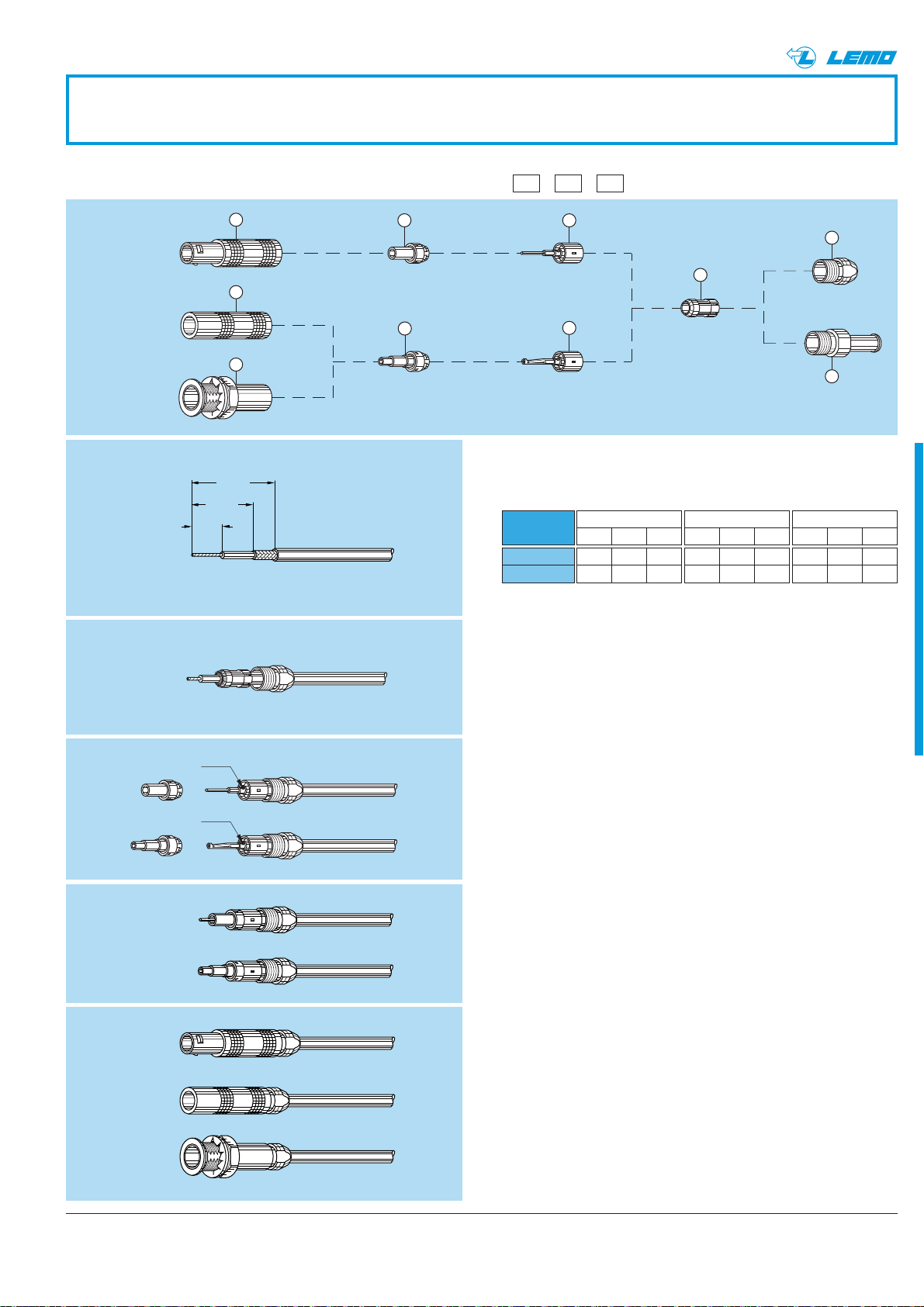
Terminating of plugs and straight sockets with cable collet
M3M2M1
T
± 0.2
S
± 0.2
L
± 0.2
1. Cable preparation
First place the bend relief (if to be used) on the cable.
Strip the cable according to dimensions below.
2. Cable termination
2.1 Place the collet nut ➀ and the collet ➁ on the cable. Fold back the
shield braid onto the conical part of the collet, and trim to the outer
edge of the collet
2.2 Slide the subassembly ➂ to trap the shield braiding and solder the
central conductor into the contact.
Straight plug
Free socket
Fixed socket
nut fixing
Crimp
Crimp
2.3 Slide the insulator ➃ onto the subassembly ➂ until it rests against
the earthing sleeve of the subassembly ➂.
2.4 Slide the assembly into the connector outer shell ➄. Screw the
collet nut ➀ into the connector outer shell ➄ using the appropriate
tool and tighten to a torque of 0.25 Nm (see “Tooling” on page 35,
36 and 37). Push the bend relief (if used) onto the collet nut.
Cable
group
1-2-3-4-8
6-7
M1
TSL
44.59
–––
M2
TSL
–––
7.5 8.5 13
M3
TSL
558
–––
Note: these terminating instructions apply to the following models:
M1 = FFA, FFE, FFF, PCA, PSA
M2 = FFY
M3 = FFC
®
5
5
5
4
4
3
1
2
3
1
Page 42
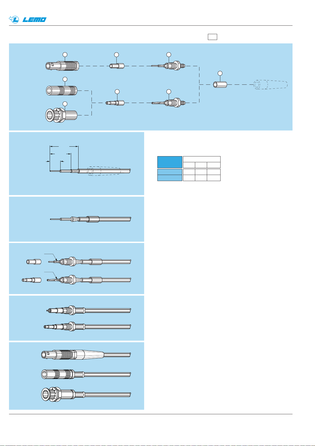
40 www.lemo.com
®
®
Terminating of plugs and straight sockets with cable crimping (crimp contact)
M4
T
± 0.2
S
± 0.2
L
± 0.2
1. Cable preparation
First place the bend relief (if to be used) on the cable.
Strip the cable according to dimensions below.
2. Cable termination
2.1 Place crimp ferrule ➀ on the cable. Widen the shield braid.
Slide the subassembly ➁ into the cable until the insulator rests
against the dielectric and the cable conductor is visible through
the contact inspection hole.
2.2 Crimp the contact with the LEMO crimping tool using
the square hole (see “Tooling” on page 37).
Gently pull the cable in order to check the crimping.
2.3 Slide the crimp ferrule ➀ onto the shield until it rests against
the crimp backnut of the subassembly ➁. Crimp with the same
LEMO crimping tool using the hexagonal opening.
Slide the insulator ➂ onto the subassembly ➁.
2.4 Slide the assembly into the connector shell ➃ and screw it
onto the subassembly ➁. Tighten using the appropriate tool
to a torque of 0.25 Nm (see “Tooling” on page 35, 36 and 37).
Push the bend relief (if used) onto the crimp ferrule ➀.
Cable
group
1-2-3-4-8
6-7
M4
TS L
7 15 19.5
7 15 21.5
Note: these terminating instructions apply to the following models:
M4 = FFS, FFV, PCS, PSS, PES
Straight plug
Free socket
Fixed socket
nut fixing
Crimp
Crimp
4
3
4
4
2
23
1
Page 43
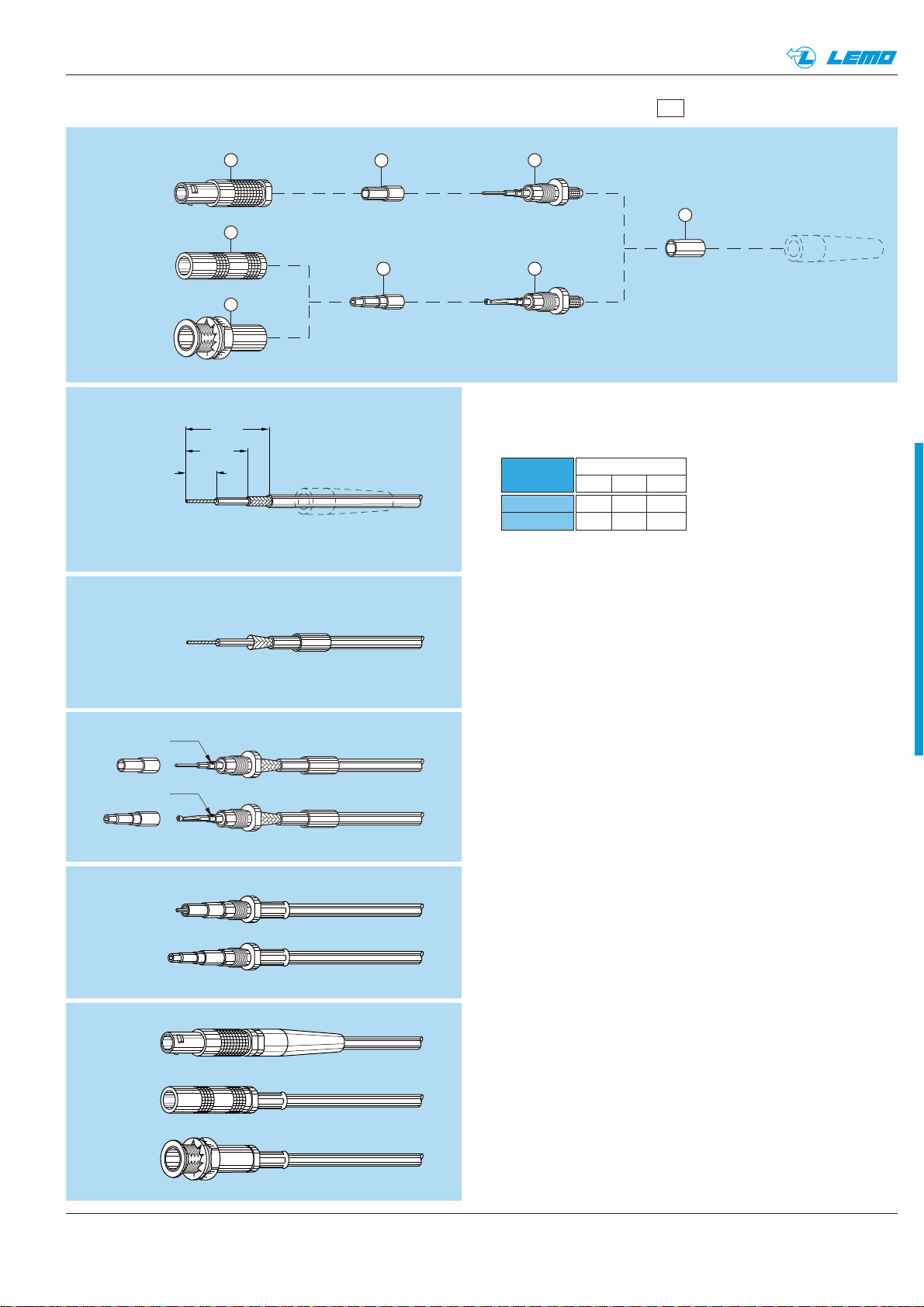
41www.lemo.com
®
®
Terminating of plugs and straight sockets with cable crimping (solder contact)
M5
T
± 0.2
S
± 0.2
L
± 0.2
1. Cable preparation
First place the bend relief (if to be used) on the cable.
Strip the cable according to dimensions below.
2. Cable terminating
2.1 Place the crimp ferrule ➀ on the cable. Widen the shield braid.
Slide the subassembly ➁ over the cable until the insulator rests
against the dielectric and the cable conductor is visible through
the contact solder hole.
2.2 Solder the conductor through the hole.
2.3 Slide the crimp ferrule ➀ onto the shield until it rests against
the crimp backnut of the subassembly ➁.
Crimp with the LEMO crimping tool using the hexagonal opening
(see “Tooling” on page 37).
Slide the insulator ➂ onto the subassembly ➁.
2.4 Slide the assembly into the connector shell ➃ and screw
it onto the subassembly ➁. Tighten using the appropriate tool
to a torque of 0.25 Nm (see tooling on pages 35, 36 and 37).
Push the bend relief (if used) onto the crimp ferrule.
Cable
group
1-2-3-4-8
6-7
M5
TS L
51217
51219
Note: these terminating instructions apply to the following models:
M5 = FFS, FFV
Straight plug
Free socket
Fixed socket
nut fixing
Solder
Solder
4
3
4
4
2
23
1
Page 44
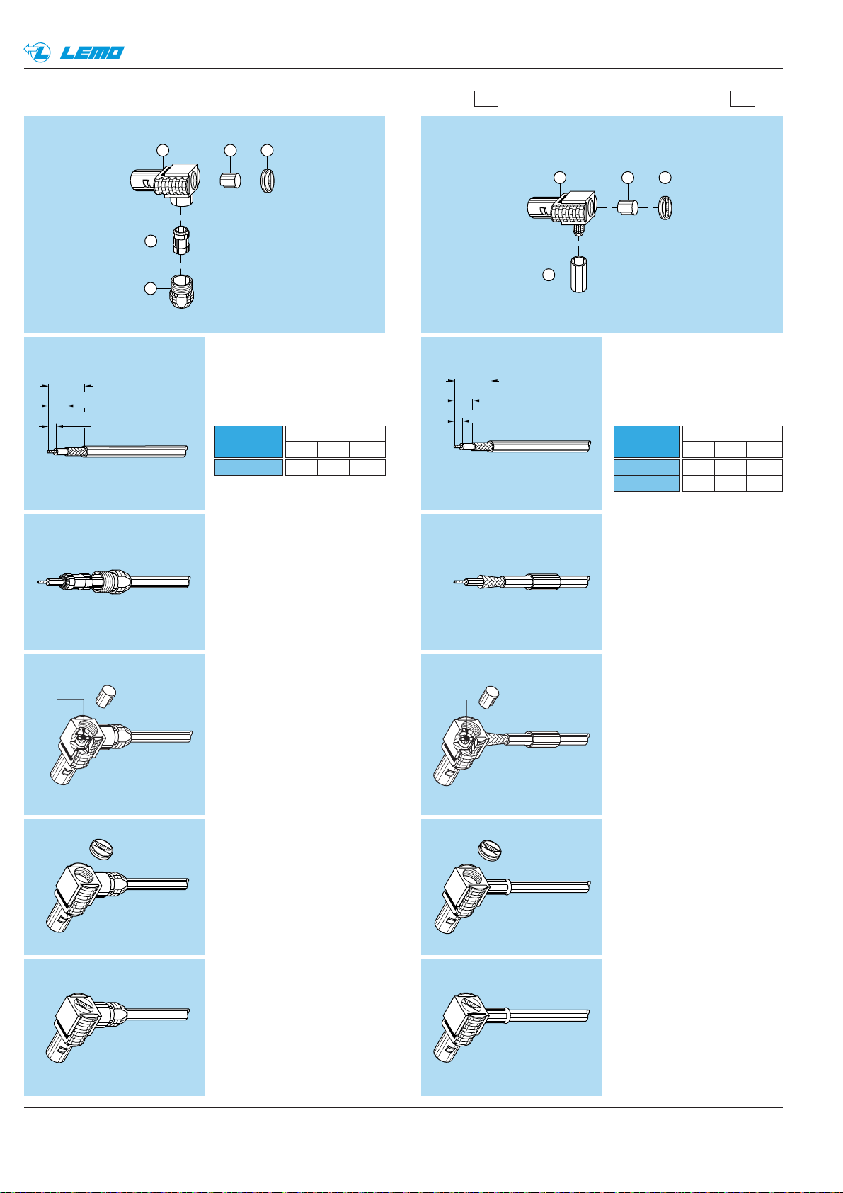
42
www.lemo.com
®
®
3
2
1
4
5
L
± 0.2
S
± 0.2
T
± 0.2
2
1
3
4
L
± 0.2
S
± 0.2
T
± 0.2
Terminating of elbow plugs (90°) with cable collet (solder contact) and cable crimp (solder contact)
M7M6
1. Cable preparation
First place the bend relief
(if to be used) on the cable.
Strip the cable according to
dimensions below.
2. Cable terminating
2.1 Place the collet nut ➀ and
collet ➁ on the cable. Fold
back the shield braid onto
the conical part of the collet,
and trim to outer edge of the
collet.
2.2 Slide the assembly into
the connector shell ➂
and tighten the collet nut ➀
using the appropriate tool
to a torque of 0.25 Nm
(see “Tooling” on page 35,
36 and 37). Check that
the cable conductor rests
in the contact slot, solder
the conductor through
the hole.
2.3 Place the insulating sleeve ➃
over the soldered contact.
2.4 Close the access hole with
the flat screw ➄.
Push the bend relief (if used)
onto the collet nut ➀.
1. Cable preparation
First place the bend relief
(if to be used) on the cable.
Strip the cable according to
dimensions below.
2. Cable terminating
2.1 Place the cable crimp ferrule
➀ on the cable and widen
the braiding.
2.2 Slide the cable into the connector shell ➁. Check that
cable conductor rests in the
contact slot, tin solder the
conductor through the hole.
Slide the crimp ferrule ➀ over
the braiding until it reaches
the connector shell ➁. Crimp
with the LEMO crimp tool
using the hexagonal opening
(see “Tooling” on page 37).
2.3 Place the insulating sleeve ➂
over the soldered contact.
2.4 Close the connector hole
with the flat screw ➃.
Push the bend relief (if used)
onto the crimping tube ➀.
Note: these terminating instructions apply to the following
models:
M6 = FLA
Note: these terminating instructions apply to the following
models:
M7 = FLS, FLV
Cable
group
1-2-3-4-8
6-7
M7
TS L
14.5 9
34.511
Cable
group
1-2-3-4-8
M6
TS L
13.56.5
Solder
Solder
Page 45
www.lemo.com
01 SERIES
Page 46
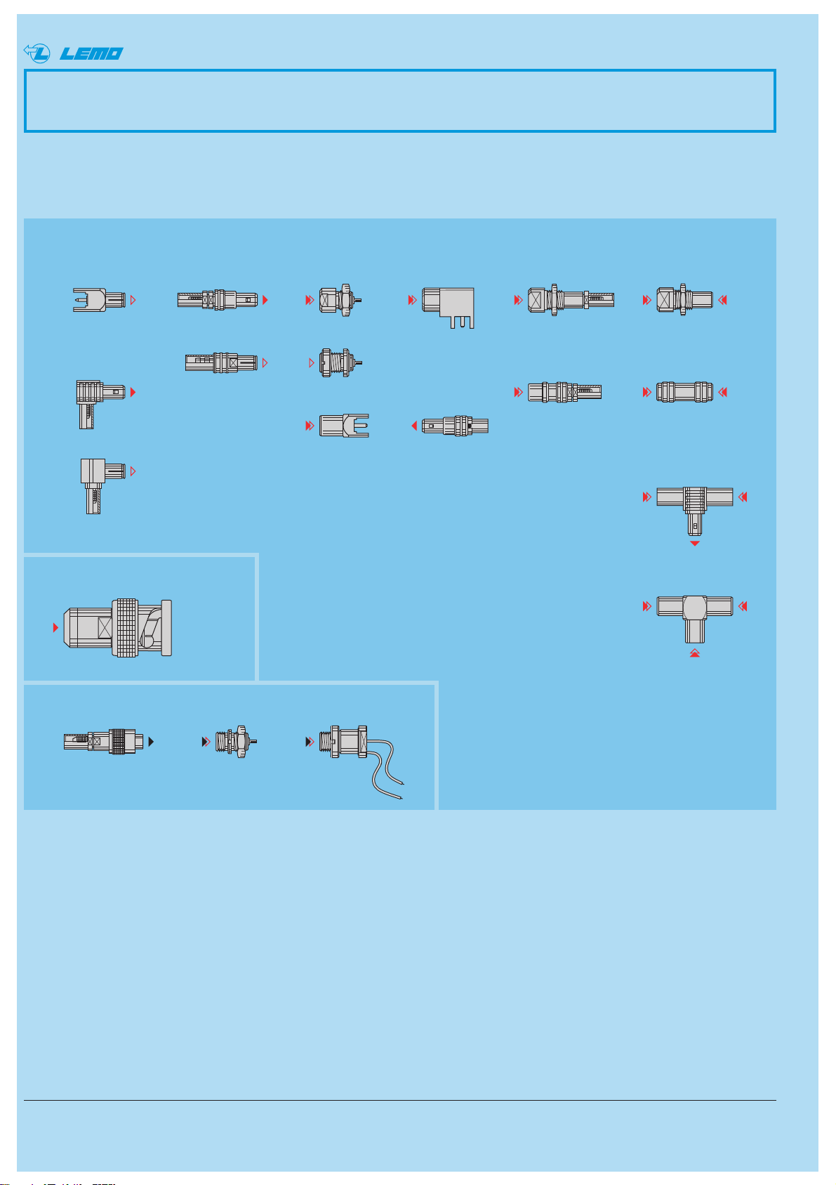
44 www.lemo.com
®
®
01 Series
The plugs and sockets of the 01 series are amongst the smallest available 50 Ω coax connectors with a self-latching
intermating capability. In spite of their small size and light weight, their technical characteristics remain excellent.
Available in a wide range of housing configurations, they are especially useful when connecting onto printed circuit
boards.
ERA
ECP
EPA
EPL
EVP
HEV
FFS
FLS
FPA
FVS
ABA
FFH
FLH
PSS
PCS
FRT
T-plug with
two sockets
T-coupler
RAD
RMA
FTA
RTA
Fixed socket
Plug with
resistor
Straight plugsFixed plug
Elbow plugs
Fixed sockets Elbow socket
Fixed coupler
Metal housing models (page 46)
Adaptors (See page 50)
Threated-latching models
(See page 50)
Free socket
Free coupler
Page 47
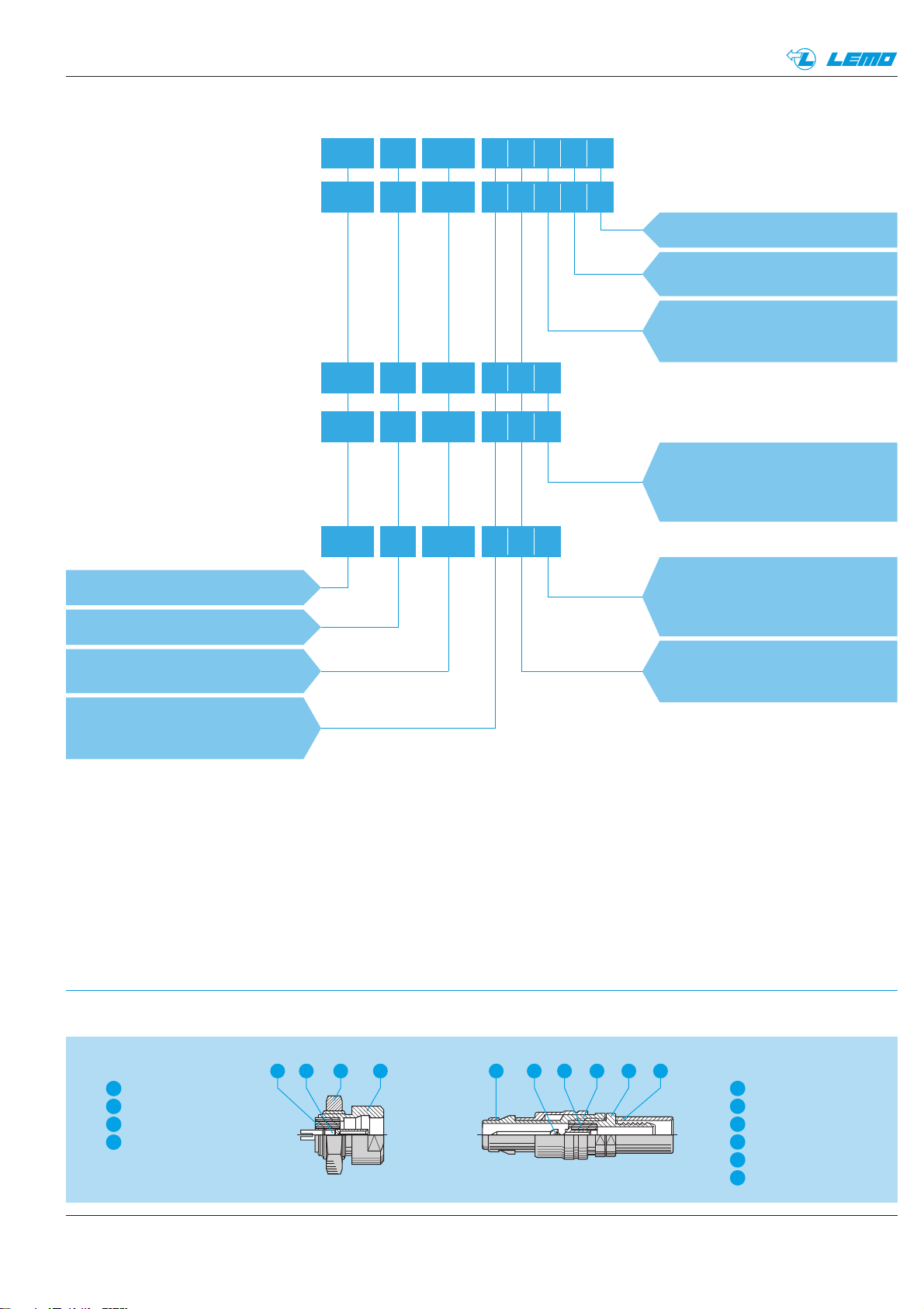
www.lemo.com
®
45
PCS
FFS 01
Cable ø
Collet type:
E = with cable crimping
250
Insert configuration:
250 = coaxial (50 Ω)
Housing :
N = brass nickel-plated
1)
D = brass gold-plated
Model: (page 44)
Series: 01
DLAE31
Fixed socket
ERA 01 250 DLL
Insulator:
L = PEEK
K = PCTFE
Contact type:
L = female solder
N = female print
D = male print
Part Numbering System
Plug
01
250
DLLE31
Free socket
Part Number Example
.. .
.. .
.. .
Fixed plug
FPA 01 250 DLD
.. .
Fixed coupler
RAD 01 250 DLM
.. .
FFS.01.250.DLAE31 = straight plug for cable crimping, 01 series, coaxial type 50 Ω, outer shell is gold-plated brass,
PEEK insulator, male solder contact, type E crimp ferrule for cable group 2, 3 or 4.
Contact type:
A = male solder
L = female solder
Contact type:
M = female-female
F = female-female-male
X = female-female-female
Part Section Showing Internal Components
Note: 1) treatment not available for the printed circuit models
®
Fixed socket
outer shell
1
female contact
2
hexagonal nut
3
insulator
4
6 2 451 3124 3
Straight plug
1
outer shell
2
latch sleeve
3
crimp ferrule
4
crimp backnut
5
male contact
insulator
6
Page 48
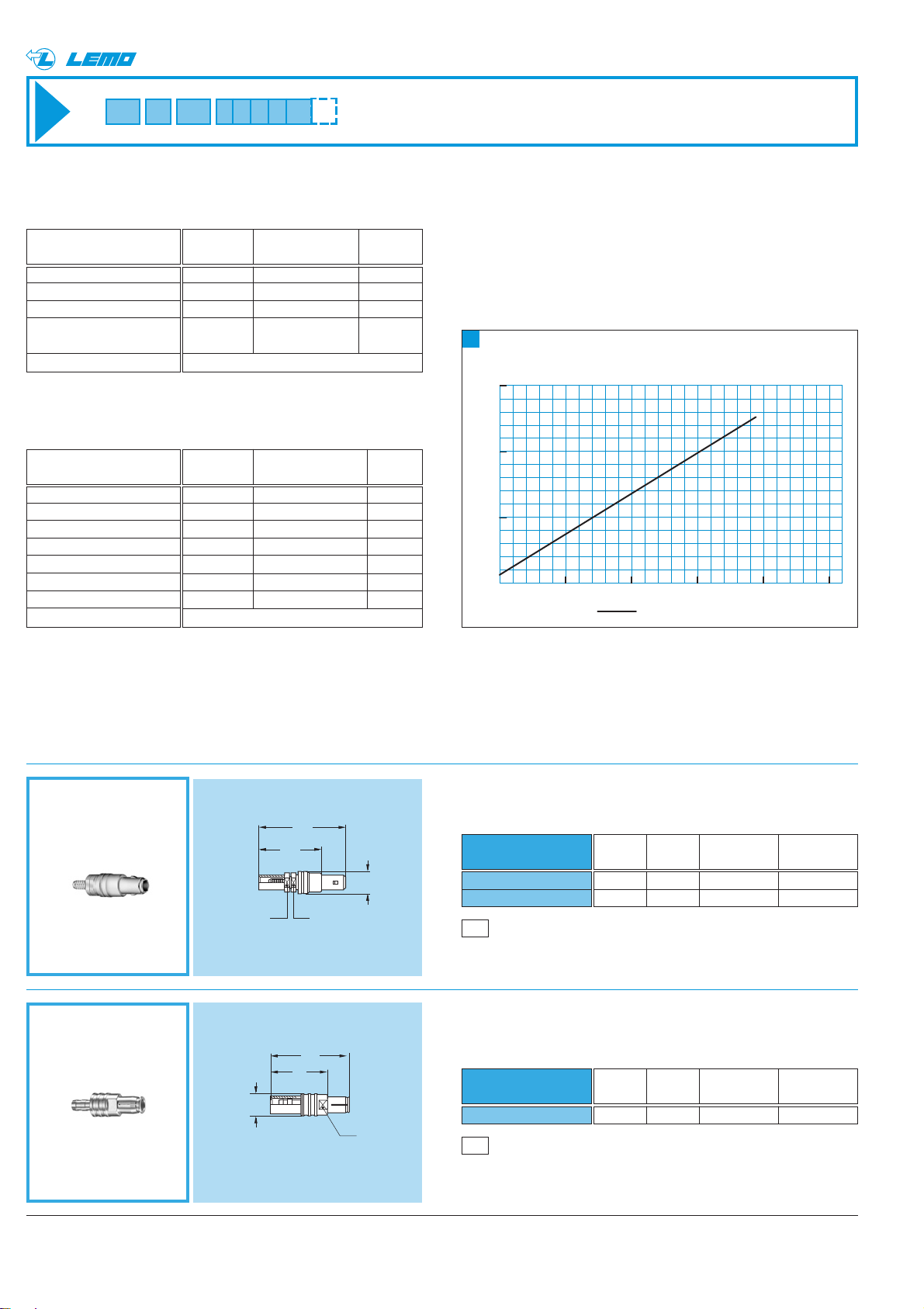
FFS Straight plug for cable crimping
46 www.lemo.com
®
®
Metal housing models
Characteristics
Value Standard Test
Contact retention force
Cable pull off force
1)
Connector pull off force
Endurance
Operating temperature
> 60 N IEC 69512-8 15a
> 100 N IEC 69512-9 17c
> 110 N IEC 69512-8 15f
> 1000
IEC 69512-5 9a
cycles
- 55°C + 230°C
Characteristics
Value Standard Method
Impedance
Operating voltage (50 Hz)
Test voltage (50 Hz)
Rated current
Contact resistance
Screen resistance
Insulating resistance
VSWR
50 Ω –
0.3 kV rms –
1.0 kV rms IEC 60512-2 4a
4 A IEC 60512-3 5a
< 6 m Ω IEC 60512-2 2a
< 3.5 m Ω
> 1012Ω IEC 60512-2 3a
see chart N°1 beside
Mechanical and climatical
Electrical
Technical Characteristics
Note:1)Depending on cable design
1N = 0.102 kg
Voltage Standing Wave Ratio
The VSWR (Voltage Standing Wave Ratio) is the value
representing the power reflected in a connection. In
most cases, the working frequency range is where
VSWR is ≤ 1.25.
Note: VSWR measured with a RG-174 A/U cable. According to IEC
60169-1-1 standard
M1
Cable assembly (page 53)
FFS.01.250.DLAE24
FFS.01.250.DLAE31
Part number
Cable Cond. Dielectric Ø Sheath Ø
group Ø max max max
1 0.55 0.95 2.35
2-3-4 0.55 1.65 3.0
M1
Cable assembly (page 53)
FFH.01.250.DLAE31
Part number
Cable Cond. Dielectric Ø Sheath Ø
group Ø max max max
2-3-4 0.55 1.65 3.0
1
V
FFH Straight plug, non-latching
for cable crimping
SWR
1.3
50Ω
1.2
1.1
1.0
1000 2000 3000 4000 5000 f
FFS + PCS
(MHz)
20
S 4
14.5
S 4
ø 5
18
13
ø 5
S 4
Page 49
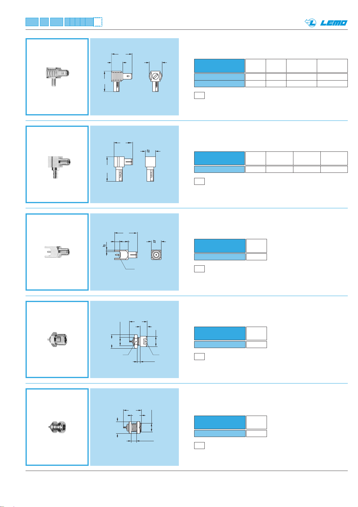
47www.lemo.com
®
®
FPA Straight plug, non-latching,
for printed circuit
FLS Elbow plug (90°) for cable crimping
ERA Fixed socket, nut fixing
ECP Fixed socket, nut fixing
(back panel mounting)
P1
Panel cut-out (page 53)
Part number
ERA.01.250.•LL
Weight
(g)
1.3
P1
Panel cut-out (page 53)
Part number
ECP.01.250.•LL
Weight
(g)
1.1
• = material of shell D or N
• = material of shell D or N
• = material of shell D or N
P4
PCB drilling pattern (page 53)
Part number
FPA.01.250.DLD
Weight
(g)
1.5
M2
Cable assembly (page 53)
FLS.01.250.•LAE24
FLS.01.250.•LAE31
Part number
Cable Cond. Dielectric Ø Sheath Ø
group Ø max max max
1 0.5 0.95 2.35
2-3-4 0.5 1.65 3.0
M3
Cable assembly, crimp contact (page 53)
FLH Elbow plug (90°) non-latching,
for cable crimping
• = material of shell D or N
Part number
FLH.01.250.•LAE31
Cable
Cond. Ø Dielectric Ø Sheath Ø
group maxi maxi maxi
2-3-4 0.4 1.65 3.0
12.1
6.6
12
ø 7.5
11
6
14.5
13
3
5
1
ø 0.9
6
10.5
4
M5x0.5
ø 8
S 7
2 max
ø 6
S 5
10.5
5.7
M5x0.5
ø 7
3.5 max
Page 50
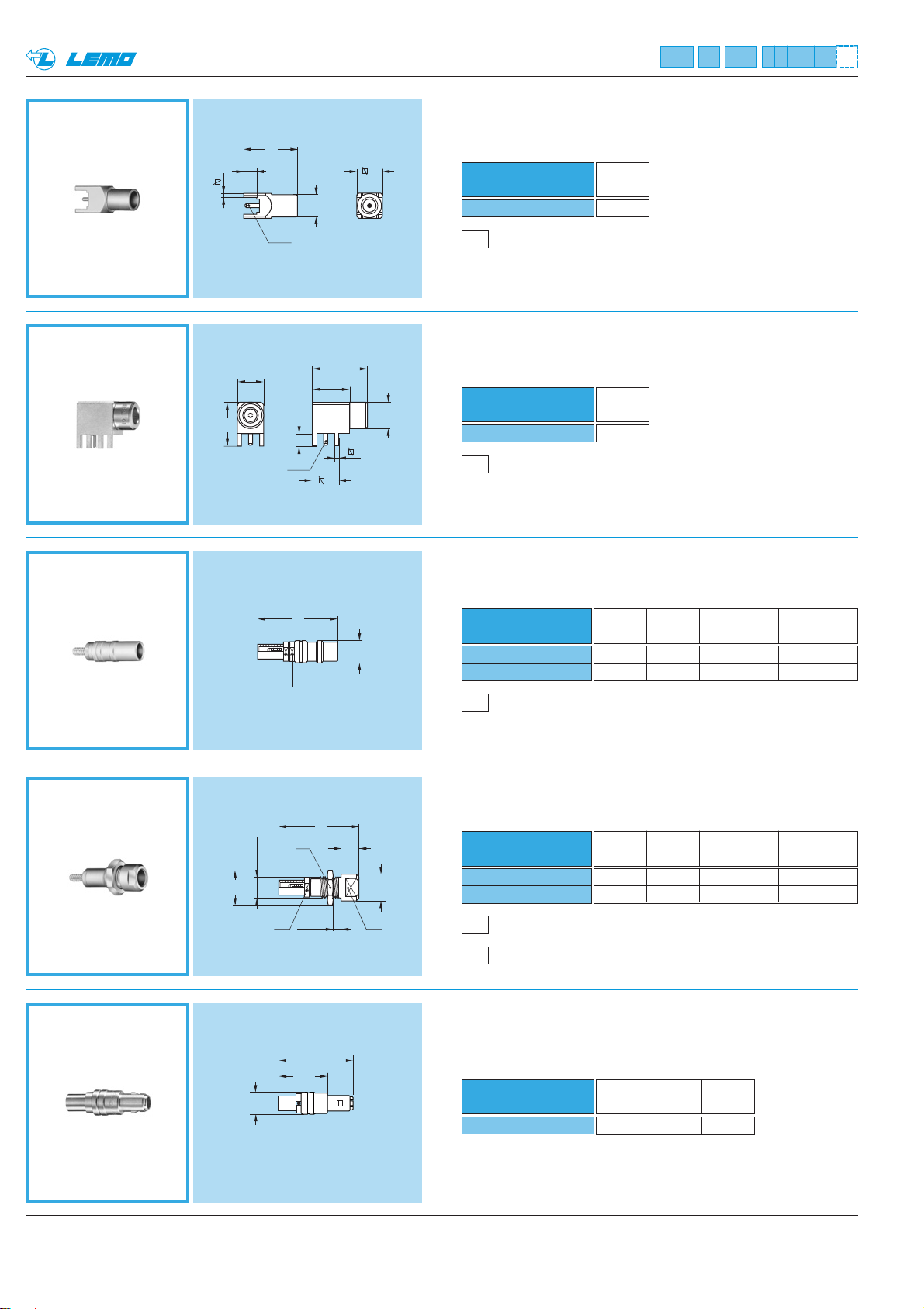
48 www.lemo.com
®
®
PSS Fixed socket, nut fixing,
for cable crimping
PCS Free socket for cable crimping
FRT Straight plug with resistor
Resistor
Weight
(g)
50 Ω 0.6 W 1.0
P1
Panel cut-out (page 53)
EPA Straight socket for printed circuit
EPL Elbow socket (90°) for printed circuit
P4
PCB drilling pattern (page 53)
Part number
EPA.01.250.DLN
Weight
(g)
1.6
P4
PCB drilling pattern (page 53)
Part number
EPL.01.250.DLN
Weight
(g)
3.2
M1
Cable assembly (page 53)
PCS.01.250.DLLE24
PCS.01.250.DLLE31
Part number
Cable Cond. Dielectric Ø Sheath Ø
group Ø max max max
1 0.55 0.95 2.35
2-3-4 0.55 1.65 3.0
M1
Cable assembly (page 53)
PSS.01.250.DLLE24
PSS.01.250.DLLE31
Part number
Cable Cond. Dielectric Ø Sheath Ø
group Ø max max max
1 0.55 0.95 2.35
2-3-4 0.55 1.65 3.0
Part number
FRT.01.250.DLA50
Note: Non standard, on request only
12
3
1
ø 5.8
ø 0.9
6
6
12.5
8.5
10
3
ø 0.9
6
ø 6
1
18
S 4 S 4
ø 5
ø 8
M5x0.5
S 4
S 7
3 maxi
18
4
ø 6
S 5
17
11.5
ø 5
Page 51
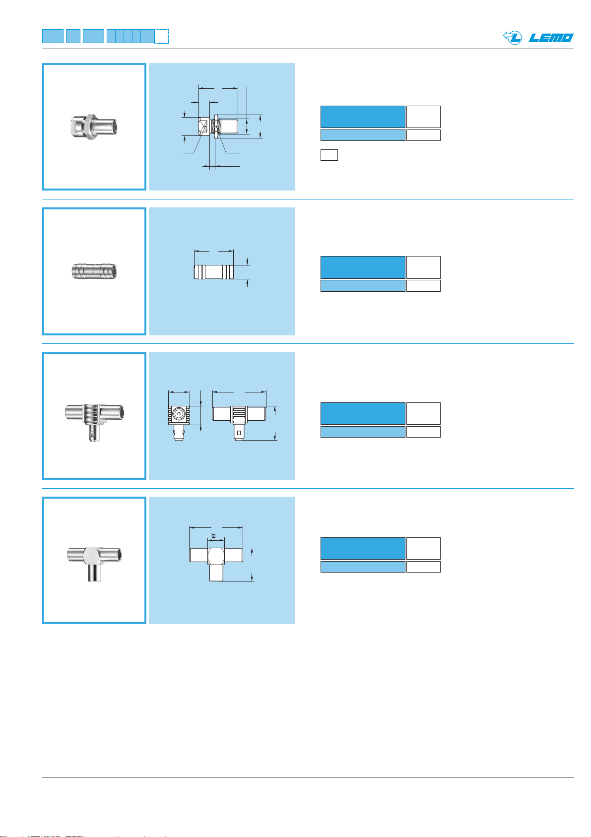
RAD Fixed coupler, nut fixing
RMA Free coupler
FTA T-plug with two sockets in line
RTA T-coupler with three sockets
49www.lemo.com
®
®
P2
Panel cut-out (page 53)
Part number
RMA.01.250.DLM
Weight
(g)
1.1
Part number
RTA.01.250.DLX
Weight
(g)
2.5
Part number
RAD.01.250.DLM
Weight
(g)
1.8
Part number
FTA.01.250.DLF
Weight
(g)
2.6
Note: Non standard, on request only
Note: Non standard, on request only
S 5
ø 6.5
14
4
2 maxi
S 7
M5.5x0.5
ø 8
14
ø 5
ø 7.5
6.8
19
12.3
19
6
11.8
Page 52
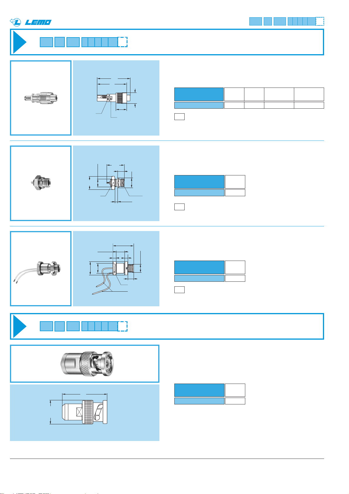
Note: this model is fitted with 2 wires AWG28 soldered before potting
50 www.lemo.com
®
®
HEV Fixed socket, round nut fixing
for threaded latching plug, watertight
(back panel mounting)
Part number
HEV.01.250.NKL
Weight
(g)
2.3
ABA Adaptor from LEMO socket
to BNC plug
Part number
ABA.01.250.NLL
Weight
(g)
17.5
Adaptors
Threaded-latching models
P3
Panel cut-out (page 53)
EVP Fixed socket, nut fixing
for threaded latching plug
Part number
EVP.01.250.NKL
Weight
(g)
1.2
FVS Straight plug, threaded latching
for cable crimping
P1
Panel cut-out (page 53)
M1
Cable assembly (page 53)
FVS.01.250.NKAE31
Part number
Cable Cond. Dielectric Ø Sheath Ø
group Ø max max max
2-3-4 0.55 1.65 3.0
20
18
ø 8
ø8
~ 78mm
~ 88mm
S 4
M5x0.5
S 7
5.5 maxi
5.0 mini
ø6
6.5
S 4
10.5
4
2 max
12.5
22
S 6
AWG 28
ø 6.3
ø 6
M5x0.5
M5x 0.5
3 min
27
ø 14.5
Page 53
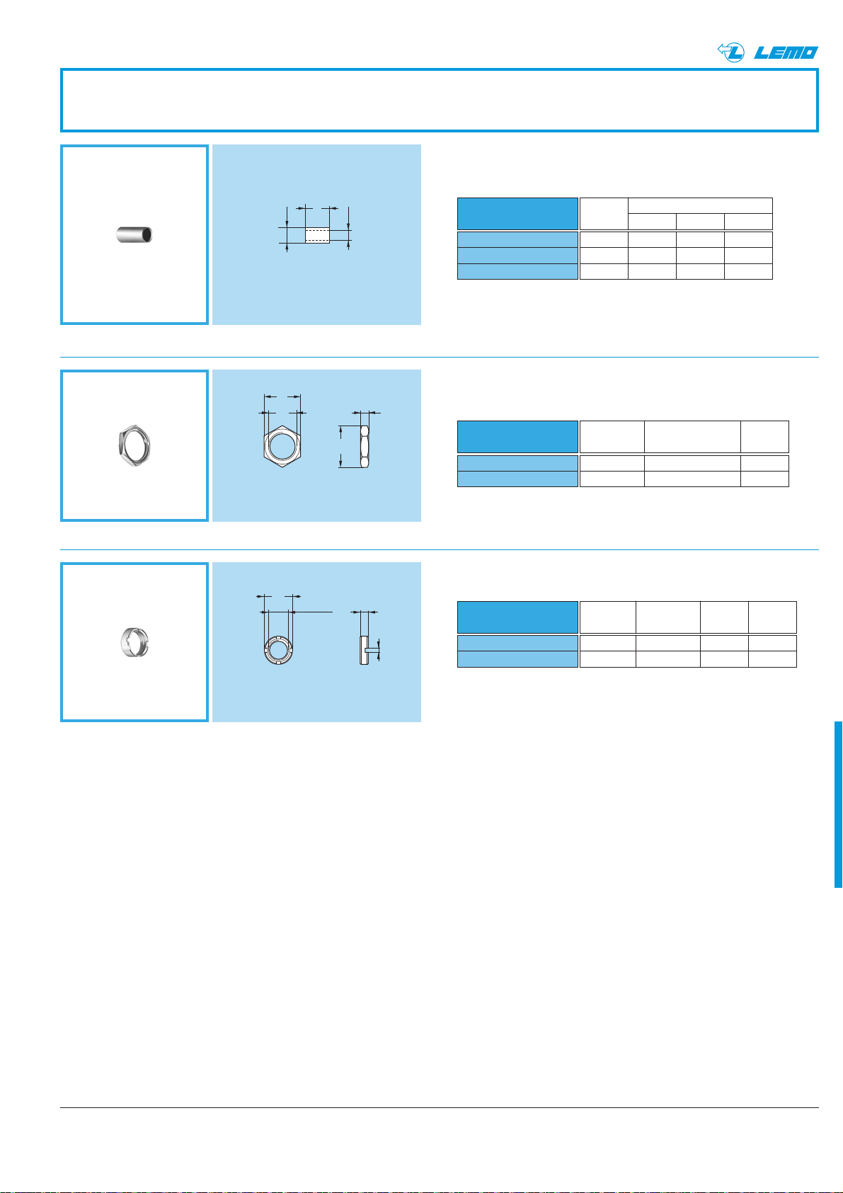
www.lemo.com
®
51
13.12.46
2-3-4 3.8 3.05 6
2-3-4 3.8 3.1 7
Cable
group
Crimp ferrule
Part number
Dim.
ØA ØB L
FFS
FFS.01.160.DA
FFS.01.161.DA
FFH.01.161.D•
1)
Note:
1)
for models FFH and FLH
Sockets and plugs to be crimped are always supplied with a
crimp ferrule. To order this accessory separately, use the
above part numbers.
● Material: Copper (UNS C 18700) nickel (3µm) + gold plated (0.5µm)
Spare parts
GEB Round nut
● Material: Brass (UNS C 38500) nickel-plated (3 µm)
Note: to order this accessory separately, use the above part number.
GEA Hexagonal nut
Part number
GEA.01.240.LN
GEA.01.241.LN
● Material: Brass (UNS C 38500) nickel-plated (3 µm)
Note: to order this accessory separately, use the above part number.
M5x0.5 ERA, EVP, PSS 0.39
M5.5x0.5 RAD 0.31
e Models Weight
(mm) (g)
Part number
GEB.01.240.LN
GEB.01.244.LN
Ø 7 ECP 2 0.30
Ø 8 HEV 4 0.50
A
Models
Slot Weight
(mm) nb. (g)
®
L
ø A
ø B
7
e
2
ø8
A
M5 x 0.5
2
1
Page 54
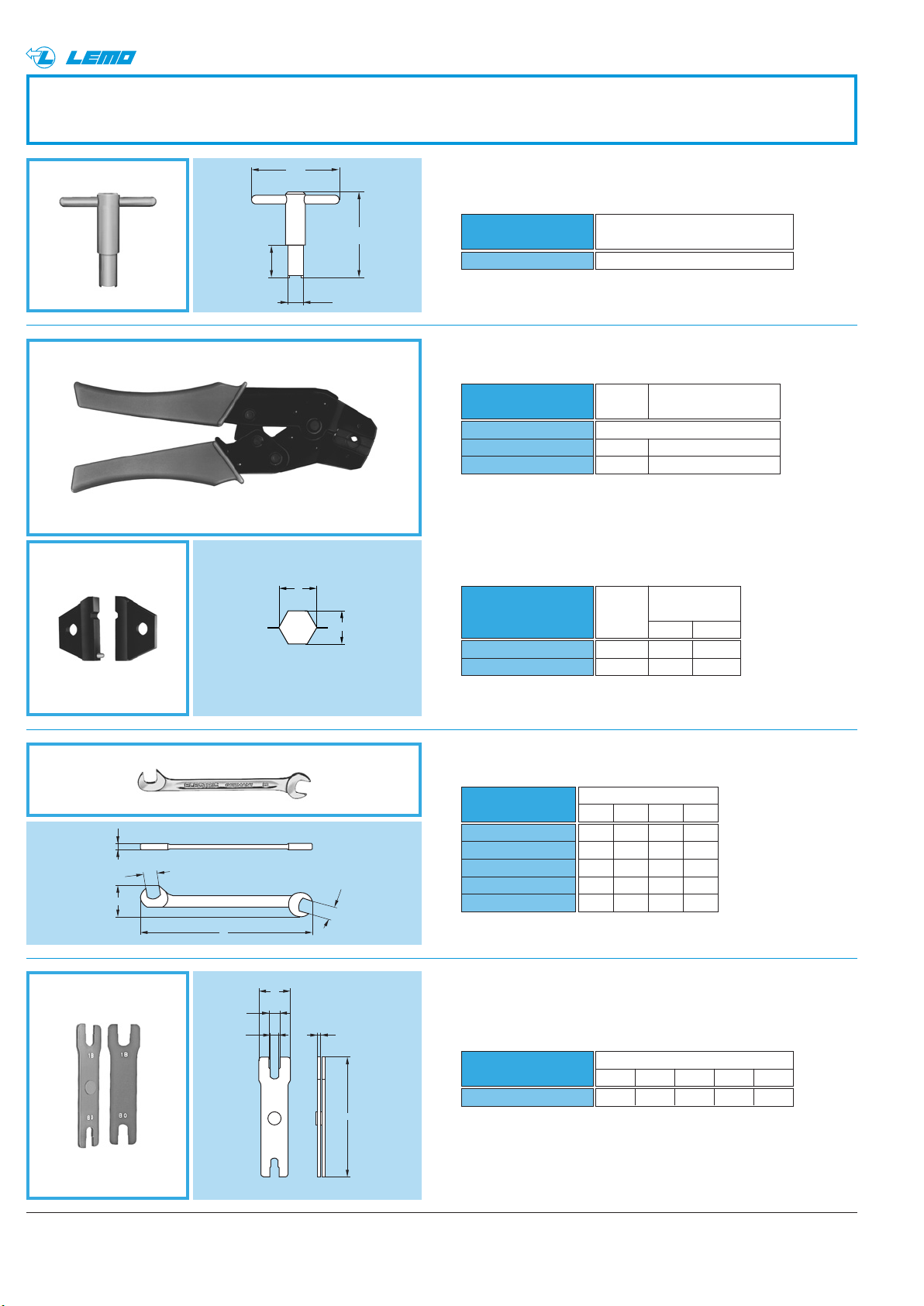
®
®
A
B
Tooling
Spanner for round nut
40
DCB
(for ECP and HEV model)
14.8
ø 7.1
39
Part number
DCB.91.097.0TN
GEB.01.240.LN / GEB.01.244.LN
Part number
of the nut
● Material: Blackened steel
Crimping tool with dieDPE
Part number
DPE.99.000.00
DPE.99.003.1K
DPE.99.003.8K
1)
2)
Note: 1) Hex cavity of DPE.99.123.1K can also be used
2) Hex cavity of DPE.99.123.8K can also be used
Dies
DPN
Part number
DPN.91.003.1K
DPN.91.003.8K
Cable Crimp collet
group ref.
Crimping tool with no die
1E24
2-3-4 E31
Cable
group
Die dimension
For shield
AB
1 3.10 2.70
2-3-4 3.80 3.30
for shield
● Dies material: Blackened steel
Flat spannerDCP
Part number
M
DCP.99.040.TC
DCP.99.045.TC
S1
N
L
N
S1
S2
S1
M
DCP.99.050.TC
DCP.99.055.TC
DCP.99.060.TC
● Material: Chrome-plated steel
Set of flat spannersDCP
Part number
DCP.91.001.TN
L
Dimensions (mm)
LMNS1
70 0.95 10.5 4.0
70 2.00 10.5 4.5
78 2.00 12.6 5.0
78 2.00 12.6 5.5
78 2.00 12.6 6.0
Dimensions
LMNS1S2
95 2.5 21 8.1 7.1
● Material: Blackened steel
52 www.lemo.com
Page 55
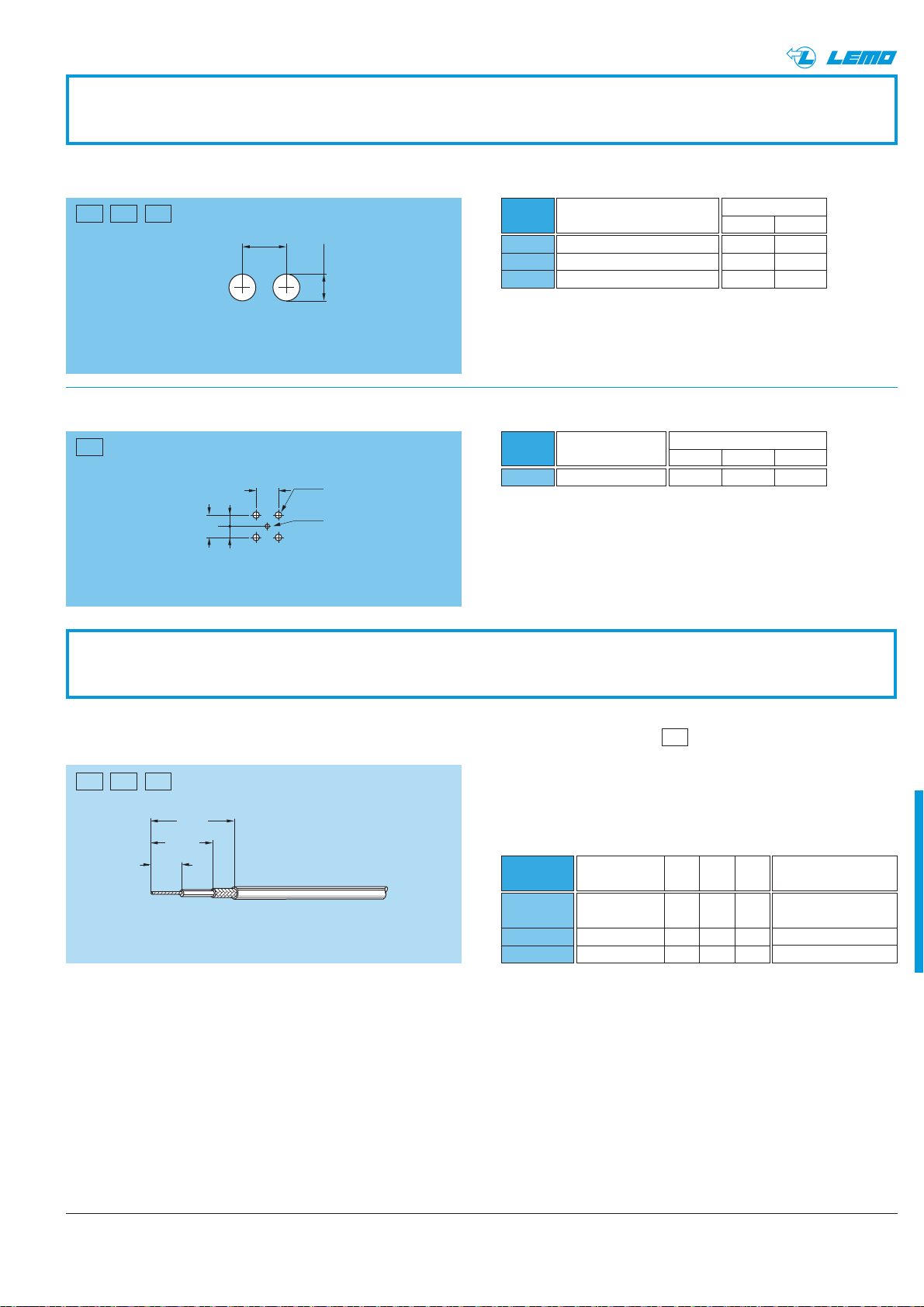
53www.lemo.com
®
Panel cut-out
Dimensions
AL
5.1 9.5
5.6 10.0
6.1 10.0
Dimensions
ABC
1.5 5.08 1.0
Recommended mounting nut torque: 1.5 Nm.
PCB drilling pattern
Panel cut-outs
Cable assembly
Terminating of plugs and straight sockets with cable crimping (solder contact)
The cable assembly of the 01.250 requires specific stripping
dimensions. See below.
However the procedure is similar to the 00.250 series.
See pages 41 and 42.
Cable
assembly
M1
M2
M3
Model T S L
FFH-FFS-FVS 3.5 6 10
PCS-PSS
FLS 1.248.5
FLM 1.2 4 10
M•
Model
EPA, FPA, EPL
Instruction of the 00 series
to use as a reference
M5 (page 41)
M7 (page 42)
M7 (page 42)
Drill
P4
Model
ERA-ECP-EVP-PSS
RAD
HEV
Cut-out
P1
P2
P3
P1 P2 P3
M1 M2 M3
P4
L mini
®
+ 0.1
0
Ø A
+ 0.1
ø A
ø C
0
+ 0.1
0
B
==
B
T
S
± 0.2
L
± 0.2
± 0.2
Page 56

54
www.lemo.com
®
®
Page 57
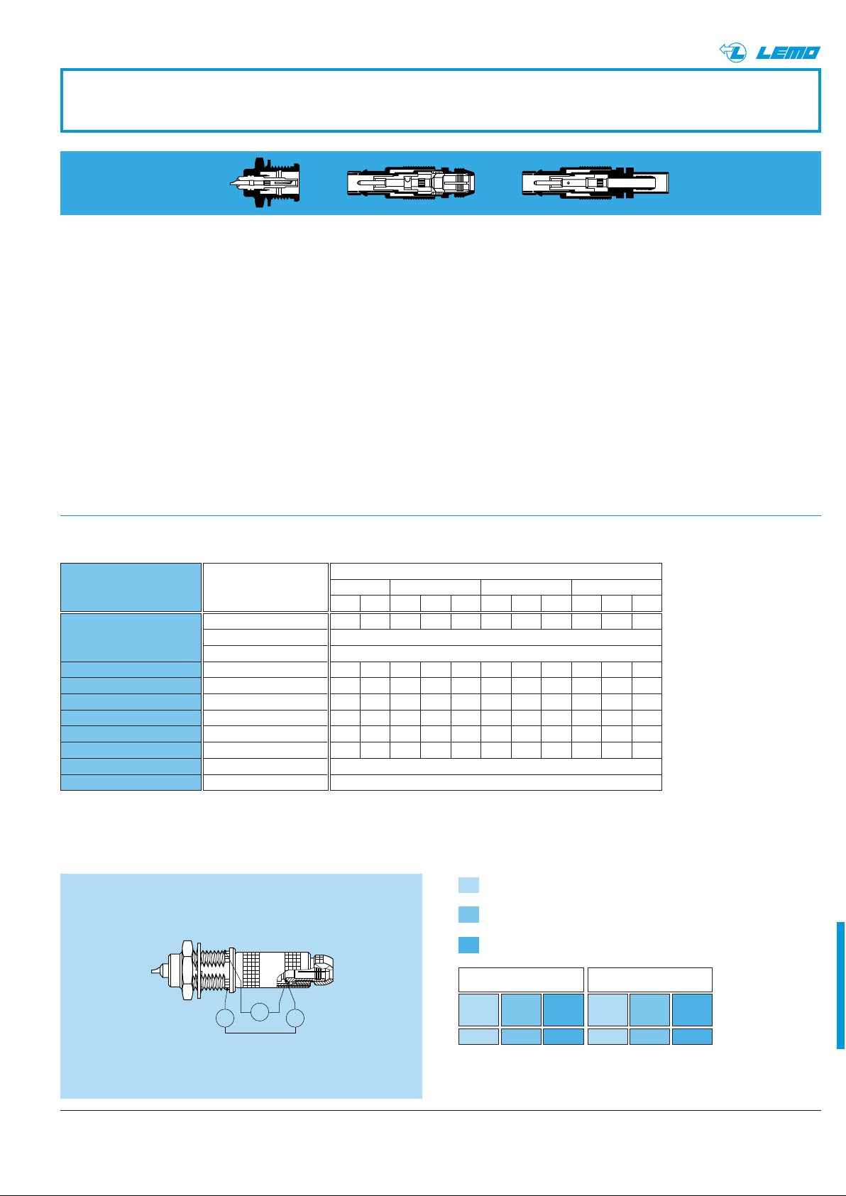
®
Outer Shell
mV
AG
®
Technical Characteristics
Brass
LEMO series 00 & 01 connectors have a brass outer
shell as standard, and this is suitable for most general
purpose applications, including civilian and military.
The brass outer shells have a nickel-plated surface which
ensures very good protection against most environments.
Alternative protective coatings available are:
– Nickel-chrome offering higher protection against salt
air and most corrosive agents
– Nickel-gold
– Nickel-black chrome. After the black chrome treatment,
the part is coated with a protective film.
The shell surface is protected by anodizing which is
available in six colors: blue, yellow, black, red, green,
and natural.
Materials and Treatment
Component
Outer shell, collet nut,
conical nut
or notched nut
Earthing crown
Latch sleeve
Crimp ferrule
Locking washer
Hexagonal nut
Other metallic components
O-ring and gaskets
Sealing resin
Material (Standard)
Brass (UNS C 38500)
Aluminium alloy
PEEK
Cu-Be (UNS C 17300)
Special Brass
Copper (UNS C 18700)
Bronze (UNS C 52100)
Brass (UNS C 38500)
Brass (UNS C 38500)
Silicone or FPM
Epoxy
Nickel Chrome Gold Black Chrome
Cu Ni Cu Ni Cr Cu Ni Au Cu Ni Cr
0.530.530.30.53 0.5– 1 2
0.53–––0.531.5–––
0.53–––0.531.5–––
0.53–––0.531.5–––
0.53–––0.530.5–––
0.53–––0.530.5–––
0.53–––0.530.5–––
Plastic Materials
A PEEK outer shell is available which offers excellent
insulating properties and is mostly used in the medical
industry. This material is suitable for gas or steam sterilization.
Other Metallic Components
In general, other components are manufactured from
brass. However, bronze is used where good elasticity is
required (for example: earthing crown).
These parts are nickel or nickel-gold plated depending on
the utilization.
Surface Treatment (µm)
Notes: The surface treatment
standards are as follows:
anodized
beige colored
without treatment
–
– nickel SAE AMS QQ N 290,
or MIL DTL 32119
– chrome SAE AMS 2460
– gold ISO 27874
– black chrome
MIL DTL 14538
with a minimum of 10 µm
lacquer protection
Electrical Characteristics
Shell electrical continuity
(measured according to IEC 60512-2 test 2f)
Values with earthing crown and latch sleeve or inner-sleeve nickel
R
1
plated.
Values with gold-plated earthing crown and nickel plated latch
R
2
sleeve or inner-sleeve.
Values with earthing crown and gold-plated latch sleeve or inner-
R
3
sleeve.
Serie 00 Serie 01
R
R
1
(mΩ)
(mΩ)
3.5 2.8 2.0
Testing current: 1A
A = Ammeter
mV = Millivoltmeter
G = Generator
R
2
(mΩ)
R
3
1
(mΩ)
N.A 2.3 1.5
R
(mΩ)
R
2
3
(mΩ)
55www.lemo.com
Page 58
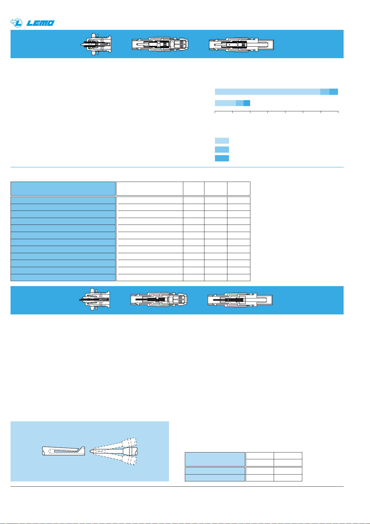
56
®
®
www.lemo.com
ASTM D 149 / IEC 60243 kV/mm 19 - 25 17.2 - 24
ASTM D 257 / IEC 60093 Ω●cm 10
16
10
18
ASTM D 257 / IEC 60093 Ω 10
15
10
17
ASTM C 177 W/K ●m 0.25 0.23
IEC 60112 V CTI 150 CTI 500
ASTM D 150 / IEC 60250 – 3.2 - 3.5 2 - 2.1
ASTM D 150 / IEC 60250 – < 0.005 < 0.0003
– °C 250 260
– °C -53 -200
ASTM D 570 / ISO R624 % < 0.3 < 0.01
–Gy10
7
2 ●10
2
UL 94 / UL 94 – V 0 V 0
Electrical Contact
rads 10310410510610710810910
10
Gray (Gy) 10110210310410510610710
8
radiation dose γ
Radiation resistance
PEEK
PTFE
Damage
minimal to mild (almost always usable)
mild to moderate (often satisfactory)
moderate to severe (unusable)
Technical Description
The secure, reliable electromechanical connection
achieved with LEMO female contacts is mainly due to
two important design features:
1. Prod proof entry which ensures perfect concentric
mating even with well used and/or carelessly handled
connectors.
2. The pressure spring that maintains a constant, even
force on the male contact when mated. The leading
edge of the spring is chamfered to slide smoothly on
the male contact, preserving the gold-plated surface
treatment and preventing undue wear.
Contact Material
LEMO female electrical contacts are made from bronze
(UNS C 54400). Bronze is chosen because of its high
modulus of elasticity, its excellent electrical conductivity
and a high mechanical strength.
LEMO male solder and print contacts are made from
brass (UNS C 38500). Male crimp contacts are made
from brass (UNS C 34500) which is ideal for crimping
onto the electrical conductor.
Conductor retention method
Both male and female contacts are available in crimp,
solder or print versions.
Insulator
Note: the technical data contained in
this chapter gives a general information about plastic materials used by
LEMO as electrical insulator materials. LEMO reserves the right to propose new material which would have
higher technical characteristics and
to withdraw any material contained
in this publication or others from
LEMO and its subsidiary companies.
LEMO only uses granulated, powdered plastic materials or bars from
specialized suppliers. LEMO is not
responsible, in any case, for these
materials.
Property
Dielectric strength
Volume resistivity at 50% HR and 23°C
Surface resistivity
Thermal conductivity
Comparative tracking index
Dielectric constant (106 Hz)
Dissipation factor (106 Hz)
Maximum continuous service temperature
Minimum continuous service temperature
Water absorption in 24h at 23°C
Radiation resistance
Flammability rating
Test
Unit PEEK PTFE
method
Technical Characteristics
Technical Description
LEMO uses virgin quality PTFE for the insulator material
of coaxial connectors, which guarantees excellent insulating properties.
LEMO also proposes PEEK (Polyether Etherketone). Its
higher mechanical strength and excellent radiation resistance make it ideal for most applications.
Insulation resistance between the contacts
and contact/shell
(measured according to IEC 60512-2 test 3a)
Multipole Unipole
PEEK PTFE
> 1012Ω > 1012Ω
> 1010Ω > 1010Ω
Insulating material
new
after humidity test
1)
Note:1)21 days
at 95% RH
according to
IEC 60068-2-3.
Page 59
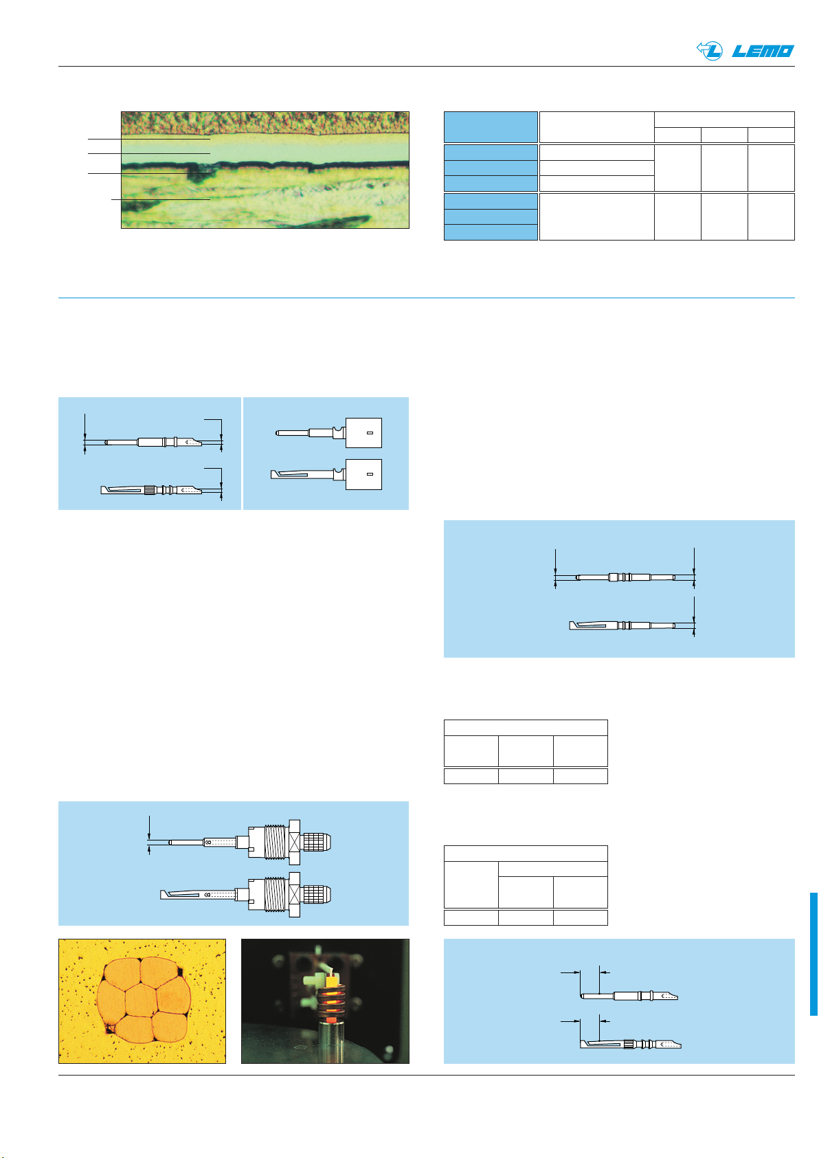
®
2.5
A
2.5
A
ø 0.7
ø 0.6
ø 0.6
ø 0.7
ø 0.7 ø 0.7
Materials and Treatments
ø 0.7
®
Au
Ni
Cu
Bronze
Notes: the standard surface treatments are as follows:
– Nickel SAE AMS QQ N 290 or MIL DTL 32119
– Gold ISO 27874
Solder Contacts
The conductor bucket of these contacts is machined at
an angle to form a cup into which the solder can flow.
Design is compatible with the use of lead-free solder.
Type
Male solder
Male crimp
Male print
Female solder
Female crimp
Female print
1)
minimum value
Material (Standard)
Brass (UNS C 38500)
Brass (UNS C 34500) 0.5 3 1.0
Brass (UNS C 38500)
Bronze
(UNS C 54400)
Surface treatment (µm)
Cu Ni Au
0.5 3 1.5
1)
Features of the LEMO crimp contacts:
– Quick and simple assembly
– Insulator is not heated during contact
to conductor assembly
– High temperature applications possible
– Increased conductor retention force
Print contacts
Print contacts are available in certain connectors versions,
mostly for the straight or elbow sockets models. Connection is made on flexible or rigid printed circuits by soldering
Crimp Contacts
The square form crimp method is used (MIL-C-22520F,
type 2) (photo 1).
The crimp method requires a controlled compression to
obtain a symmetrical deformation of the conductor
strand and of the contact material. The radial hole in the
side of the contact enables correct positioning of the
conductor within the contact to be verified. A good
crimping is characterized by a small conductor section
reduction and by the quite closed free spaces.
The LEMO crimp contacts are factory annealed to relieve
internal stresses, and reduce the risk of the material
work hardening during the crimping process.
During this process, an induction heating machine
designed by LEMO’s Research and Development
Department is used (photo 2).
Contact Resistance in Relation to Numbers of Mating
Cycles (mesured according to IEC 605/2-2 test 2a)
Contact resistance (mΩ)
1000 3000 5000
cycles cycles cycles
5.6 5.7 6.1
Maximum values mesured after the
mating cycles and the salt spray
test according to IEC 60512-6 test
11f.
Thickness comparison between the outside
and the inside of female contacts
Gold thickness
male
(µm)
1.0 1.5 70
female
outside inside
(µm) (%)
A = inspection point
12
57www.lemo.com
Page 60
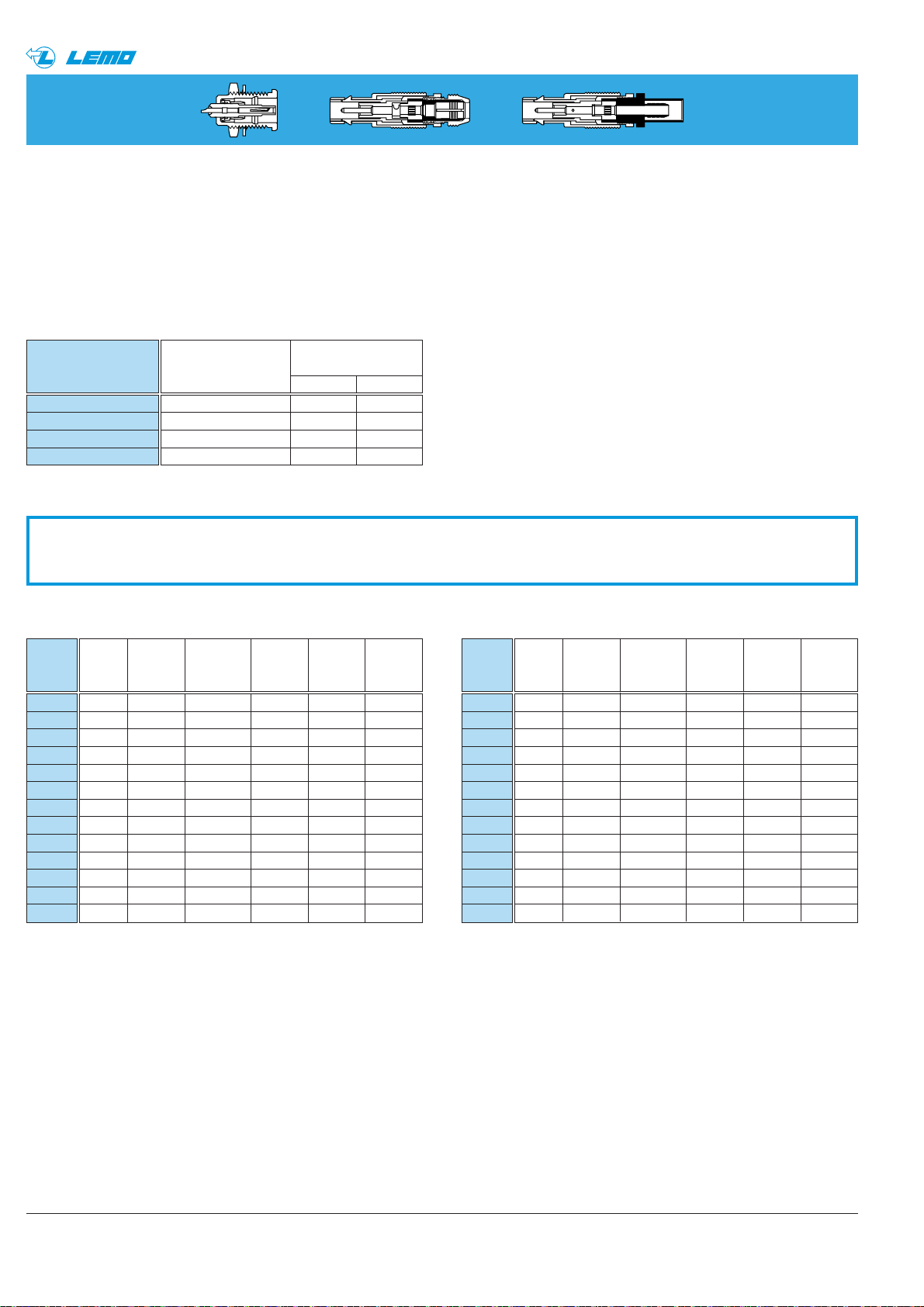
58
®
®
www.lemo.com
Note: collet nut tightening torque: maximum 0.25 Nm (1N = 0.102 kg)
Component
Earthing sleeve
Collet
Crimp ferrule
Collet nut
Surface Treatment
(µm)
Material (Standard)
Cu Ni
Brass (UNS C 38500) 0.5 3
Brass (UNS C 38500) 0.5 3
Copper (UNS C 18700) 0.5 3
Brass (UNS C 38500) 0.5 3
Material and Treatment
Return Transmiss. Reflected Transmit. Reflected
loss loss voltage power power
(dB) (dB) coefficient (%) (%)
VSWR
(dB)
Return Transmiss. Reflected Transmit. Reflected
loss loss voltage power power
(dB) (dB) coefficient (%) (%)
VSWR
(dB)
0 0.000 0.00 100.0 0.0
0.1 46.1 0.000 0.00 100.0 0.0
0.2 40.1 0.000 0.01 100.0 0.0
0.3 36.6 0.001 0.01 100.0 0.0
0.3 34.2 0.003 0.03 100.0 0.0
0.4 32.3 0.003 0.02 99.9 0.1
0.5 30.7 0.004 0.03 99.9 0.1
0.6 29.4 0.005 0.03 99.9 0.1
0.7 28.3 0.006 0.04 99.9 0.1
0.7 27.3 0.008 0.04 99.8 0.2
0.8 26.4 0.010 0.05 99.8 0.2
0.9 25.7 0.012 0.05 99.7 0.3
1.0 24.9 0.014 0.06 99.7 0.3
VSWR effect on transmitted power
VSWR
1.00
1.01
1.02
1.03
1.04
1.05
1.06
1.07
1.08
1.09
1.10
1.11
1.12
1.1 24.3 0.016 0.06 99.6 0.4
1.1 23.7 0.019 0.07 99.6 0.4
1.2 23.1 0.021 0.07 99.5 0.5
1.3 22.6 0.024 0.07 99.5 0.5
1.4 22.1 0.027 0.08 99.4 0.6
1.4 21.7 0.030 0.08 99.3 0.7
1.5 21.2 0.033 0.09 99.2 0.8
1.6 20.8 0.036 0.09 99.2 0.8
1.7 20.4 0.039 0.10 99.1 0.9
1.7 20.1 0.043 0.10 99.0 1.0
1.8 19.7 0.046 0.10 98.9 1.1
1.9 19.4 0.050 0.11 98.9 1.1
1.9 19.1 0.054 0.11 98.8 1.2
VSWR
1.13
1.14
1.15
1.16
1.17
1.18
1.19
1.20
1.21
1.22
1.23
1.24
1.25
Technical tables
Cable Fixing
Cable fixing onto LEMO connectors is determined by the connector model. This is achieved either with a cable collet
system or with hexagonal crimping (MIL-C-22520F, type 2).
The collet system cable fixing is made without any special tooling. The crimping method guarantees a good electrical
continuity of the shield which improves greatly the shielding efficiency of the cable/connector link.
Page 61
59www.lemo.com
®
®
PLEASE READ AND FOLLOW ALL INSTUCTIONS CAREFULLY AND CONSULT ALL RELEVENT NATIONAL AND
INTERNATIONAL SAFETY REGULATIONS FOR YOUR APPLICATION.
IMPROPER HANDLING, CABLE ASSEMBLY, OR WRONG USE OF CONNECTORS CAN RESULT IN HAZARDOUS
SITUATIONS.
1. SHOCK AND FIRE HAZARD
Incorrect wiring, the use of damaged components, presence of foreign objects (such as metal debris), and / or residue
(such as cleaning fluids), can result in short circuits, overheating, and / or risk of electric shock.
Mated components should never be disconnected while live as this may result in an exposed electric arc and local
overheating, resulting in possible damage to components.
2. HANDLING
Connectors and their components should be visually inspected for damage prior to installation and assembly. Suspect
components should be rejected or returned to the factory for verification.
Connector assembly and installation should only be carried out by properly trained personnel. Proper tools must be
used during installation and / or assembly in order to obtain safe and reliable performance.
3. USE
Connectors with exposed contacts should never be live (or on the current supply side of a circuit). Under general
conditions voltages above 30 VAC and 42 VDC are considered hazardous and proper measures should be taken to
eliminate all risk of transmission of such voltages to any exposed metal part of the connector.
4. TEST AND OPERATING VOLTAGES
The maximum admissible operating voltage depends upon the national or international standards in force for the
application in question. Air and creepage distances impact the operating voltage; reference values are indicated in the
catalog however these may be influenced by PC board design and / or wiring harnesses.
The test voltage indicated in the catalog is 75% of the mean breakdown voltage; the test is applied at 500 V/s and the
test duration is 1 minute.
5. CE MARKING
CE Marking is applied to a complete product or device, and implies that the device complies with one or several
European safety directives.
CE Marking can not be applied to electromechanical components such as connectors.
6. PRODUCT IMPROVEMENTS
The LEMO Group reserves the right to modify and improve to our products or specifications without providing prior
notification.
Product safety notice
Page 62

60
®
®
www.lemo.com
Page 63
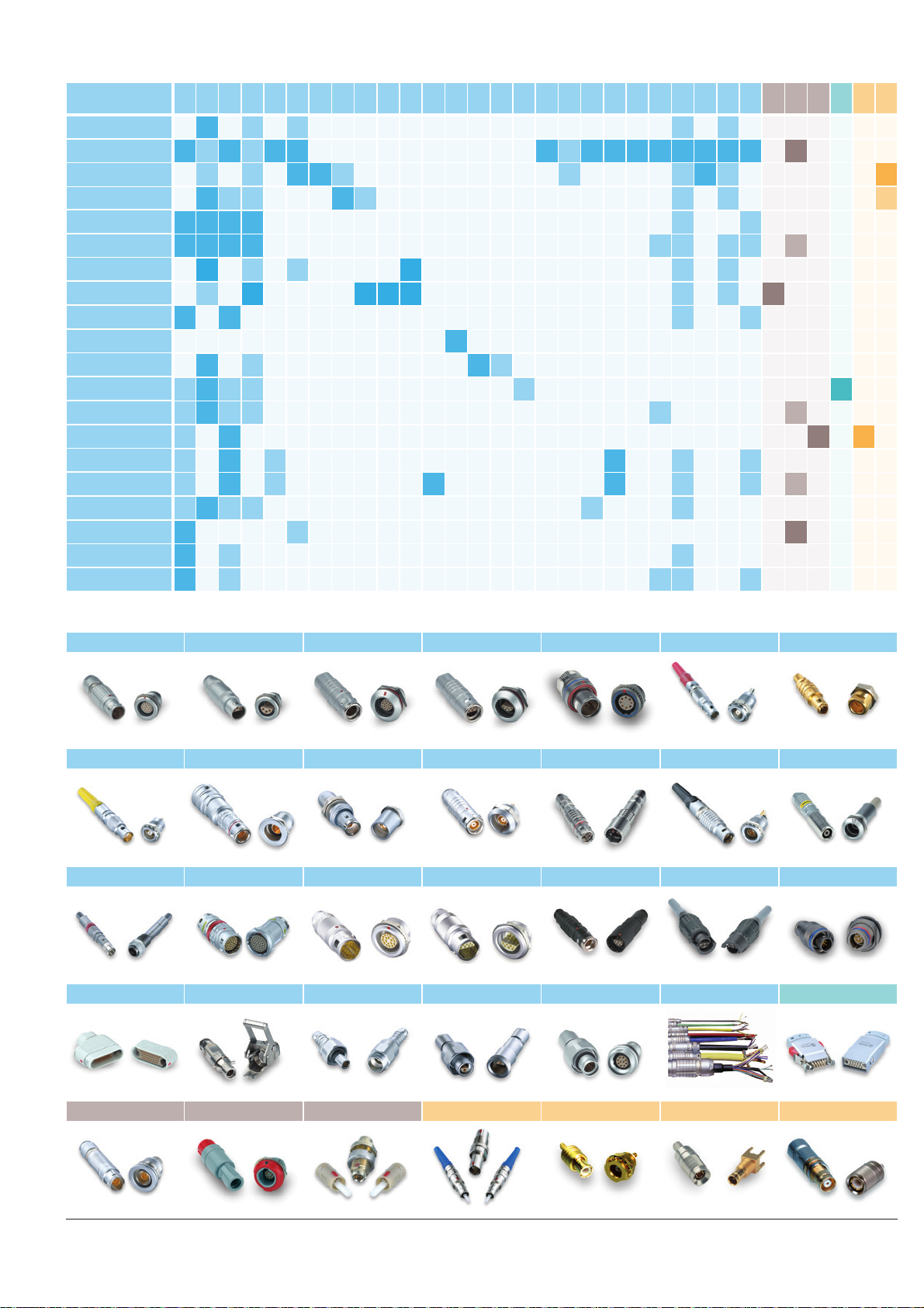
No reproduction or use without express permission of editorial or pictorial content, in any manner.
LEMO SA reserves the right to modify and improve specifications, at all times, without any notification.
B S K E F 00 01 0A 3T 4A 4M
3K.
93C
1D Y 05 5G 2G 2C L H M R N 03 V W F P D K/S 01 DIN
LEMO complete product range
Unipole
Multipole
Coaxial 50 Ω
Coaxial 75 Ω
Multi Coaxial
Mixed Coax + LV
Triaxial 50 Ω
Triaxial 75 Ω
Mixed Triax + LV
Quadrax
High Voltage
Multi High Voltage
Mixed HV + LV
Fibre Optic
Multi Fibre Optic
Mixed FO + LV
Thermocouple
Fluidic
Multi Fluidic
Mixed Fluidic + LV
• •
Most frequently used in darker colour
•
included in this catalogue
B Series Keyed S Series K Series Keyed E Series F Series Keyed 00 Series 01 Series
0A Series 3T Series 4A Series 4M Series Keyed 3K.93C Series Keyed 1D Series Y Series
05 Series 5G Series Keyed 2G Series Keyed 2C Series L Series Keyed H Series M Series Keyed
R Series Keyed N Series Keyed 03 Series Keyed V Series W Series Keyed Cable assembly K/S Series Keyed
REDEL F Series P REDEL Series Keyed D REDEL Series 01 Series Keyed VAA Series SAA Series TAA Series
Page 64
LEMO HEADQUARTERS
SWITZERLAND
LEMO SA
Chemin des Champs-Courbes 28 - P.O. Box 194 - CH-1024 Ecublens
Tel. (+41 21) 695 16 00 - Fax (+41 21) 695 16 02 - e-mail: [email protected]
LEMO SUBSIDIARIES
AUSTRIA
LEMO Elektronik GesmbH
Lemböckgasse 49/E6-3
1230 Wien
Tel: (+43 1) 914 23 20 0
Fax:(+43 1) 914 23 20 11
[email protected]
BRAZIL
LEMO Latin America Ltda
Av. José Rocha Bonfim,
214 Salas 224 / 225
Condomínio Praça Capital
Ed. Chicago
Campinas / SP - Brasil 13080-650
Tel: +55 (11) 98689 4736
[email protected]
CANADA
LEMO Canada Inc
44 East Beaver Creek Road, unit 20
Richmond Hill, Ontario L4B 1G8
Tel: (+1 905) 889 56 78
Fax: (+1 905) 889 49 70
[email protected]
CHINA / HONG KONG
LEMO Electronics (Shanghai) Co., Ltd
First Floor, Block E,
18 Jindian Road, Pudong
Shanghai, China, 201206
Tel: (+86 21) 5899 7721
Fax: (+86 21) 5899 7727
[email protected]
DENMARK
LEMO Denmark A/S
Gammel Mosevej 46
2820 Gentofte
Tel: (+45) 45 20 44 00
Fax: (+45) 45 20 44 01
[email protected]
FRANCE
LEMO France Sàrl
24/28 Avenue Graham Bell
Bâtiment Balthus 4
Bussy Saint Georges
77607 Marne la Vallée Cedex 3
Tel: (+33 1) 60 94 60 94
Fax: (+33 1) 60 94 60 90
[email protected]
GERMANY
LEMO Elektronik GmbH
Hanns-Schwindt-Str. 6
81829 München
Tel: (+49 89) 42 77 03
Fax: (+49 89) 420 21 92
[email protected]
HUNGARY
REDEL Elektronika Kft
Nagysándor József u. 6-12
1201 Budapest
Tel: (+36 1) 421 47 10
Fax: (+36 1) 421 47 57
[email protected]
ITALY
LEMO Italia srl
Viale Lunigiana 25
20125 Milano
Tel: (+39 02) 66 71 10 46
Fax: (+39 02) 66 71 10 66
[email protected]
JAPAN
LEMO Japan Ltd
2-7-22, Mita,
Minato-ku, Tokyo, 108-0073
Tel: (+81 3) 54 46 55 10
Fax: (+81 3) 54 46 55 11
[email protected]
NETHERLANDS / BELGIUM
LEMO Connectors Benelux
De Trompet 1060
1967 DA Heemskerk
Tel. (+31) 251 25 78 20
Fax (+31) 251 25 78 21
[email protected]
NORWAY / ICELAND
LEMO Norway A/S
Stanseveien 6B
0975 Oslo
Tel: (+47) 22 91 70 40
Fax: (+47) 22 91 70 41
[email protected]
SINGAPORE
LEMO Asia Pte Ltd
4 Leng Kee Road,
#06-09 SiS Building
Singapore 159088
Tel: (+65) 6476 0672
Fax: (+65) 6474 0672
[email protected]
SPAIN / PORTUGAL
IBERLEMO SAU
Brasil, 45, 08402 Granollers
Barcelona
Tel: (+34 93) 860 44 20
Fax: (+34 93) 879 10 77
[email protected]
SWEDEN / FINLAND
LEMO Nordic AB
Mariehällsvägen 39A
168 65 Bromma
Tel: (+46 8) 635 60 60
Fax: (+46 8) 635 60 61
[email protected]
SWITZERLAND
LEMO Verkauf AG
Grundstrasse 22 B
6343 Rotkreuz
Tel: (+41 41) 790 49 40
[email protected]
UNITED KINGDOM
LEMO UK Ltd
12-20 North Street
Worthing, West Sussex,
BN11 1DU
Tel: (+44 1903) 23 45 43
[email protected]
USA
LEMO USA Inc
P.O. Box 2408
Rohnert Park, CA 94927-2408
Tel: (+1 707) 578 88 11
(+1 800) 444 53 66
Fax:(+1 707) 578 08 69
[email protected]
© CAT.NC.LEN.P0509, pdf updated September 2016
LEMO DISTRIBUTORS
AUSTRALIA, CHILE, CZECH REPUBLIC, GREECE, INDIA, ISRAEL,
NEW ZEALAND, PAKISTAN, POLAND, RUSSIA, SOUTH AFRICA,
SOUTH KOREA, TAIWAN, TURKEY, UKRAINE
www.lemo.com
 Loading...