

Page 1
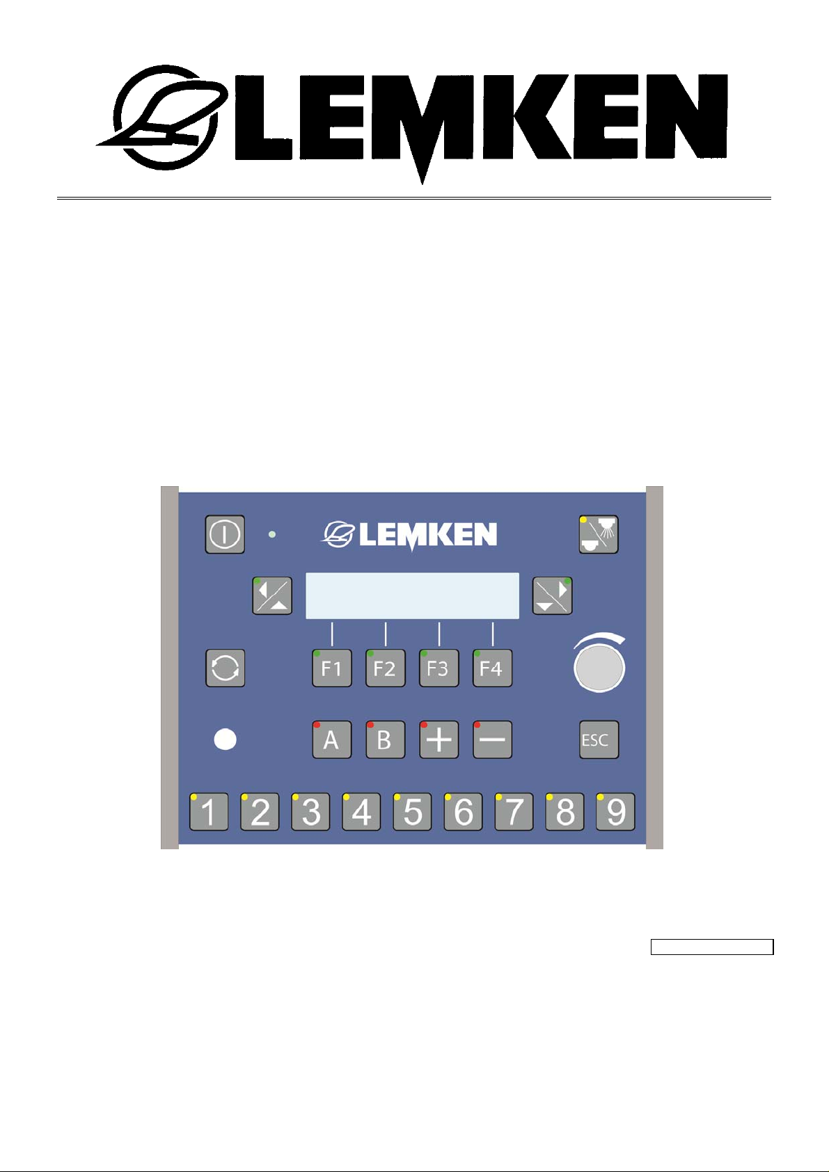
Operating Instructions
Controls
Ecospray
Sirius 10
- en -
Item no. 17510543
3/03.14
LEMKEN GmbH & Co. KG
Weseler Straße 5, 46519 Alpen / Germany
Telephone +49 28 02 81 0, Fax +49 28 02 81 220
[email protected], www.LEMKEN.com
Page 2

Dear customer,
Thank you for the trust you have placed in us by purchasing this device. The device can only be used to its full advantage when operated and used properly.
When the device was delivered, you will already have been instructed in operation, adjustment and maintenance by your dealer. However, this brief instruction is
not a substitute for thorough study of the operating instructions.
These operating instructions will help to familiarise you with the LEMKEN GmbH &
Co. KG device and the options available for using it.
The operating instructions contain important information about how to operate the
device safely, properly and efficiently. Following the instructions will help to prevent hazards, faults and down times and will increase reliability and service life.
Read the operating instructions carefully and attentively before commissioning.
Make sure that the operating instructions are always available at the location
where the device is used.
The operating instructions must be read and followed by anyone who is involved
in carrying out the following work:
Coupling and uncoupling
Adjustments
Operation
Maintenance and repairs
Troubleshooting, and
Final shutdown and disposal.
2
Page 3

Spare parts ordering
This device is supplied with a specification listing all assemblies that are relevant
for the product. The spare parts list valid for your device includes both those assemblies relevant to you and those that are not intended for your device. Make
sure that you only order spare parts that belong to the assemblies that can be
found on your specification or the enclosed print out. When ordering spare parts,
state the type designation and serial number of the device. This information can
be found on the rating plate. Enter this data in the fields below so that it is always
to hand.
Type designation:
Serial number:
Remember that you should only use genuine LEMKEN spare parts. Reproduction
parts have a negative influence on the function of the device, have a shorter service life and present risks and hazards that cannot be estimated by LEMKEN
GmbH & Co. KG. They also increase the maintenance costs.
Service and spare parts
Information on service and spare parts is available from your local dealer or our
website at www.lemken.com.
3
Page 4

Contents
CONTENTS
Contents ........................................................................................................................... 4
1 General information ................................................................................................ 10
1.1 Liability ......................................................................................................................... 10
1.2 Guarantee ..................................................................................................................... 10
1.3 Copyright ..................................................................................................................... 11
1.4 Optional accessories .................................................................................................. 11
2 Symbols used in the Operating Instructions ........................................................ 12
2.1 Hazard classes ............................................................................................................ 12
2.2 Information ................................................................................................................... 12
2.3 Environmental protection ........................................................................................... 12
2.4 Indication of passages ................................................................................................ 13
3 Safety measures and precautions ......................................................................... 14
3.1 Target group ................................................................................................................ 14
3.2 Intended use ................................................................................................................ 14
4 Handing over the device ......................................................................................... 15
4.1 Disposal ....................................................................................................................... 15
5 Preparations on the tractor .................................................................................... 16
5.1 General ......................................................................................................................... 16
5.2 Connections on the operating terminal ..................................................................... 16
5.3 Socket .......................................................................................................................... 17
5.4 Operating voltage and fuses ...................................................................................... 17
6 Preparations on the operating terminal ................................................................ 18
6.1 Segment box ................................................................................................................ 18
6.2 Joystick box ................................................................................................................. 19
6.3 Matrix operating terminal ............................................................................................ 19
6.3.1 Connections ............................................................................................................... 19
6.3.2 Switching on the matrix operating terminal ................................................................ 21
4
Page 5

Contents
6.3.3 Switching off the matrix operating terminal ................................................................ 21
7 Ecospray operating terminal .................................................................................. 22
7.1 Overview ...................................................................................................................... 22
7.2 Function ....................................................................................................................... 22
7.3 Other displays ............................................................................................................. 23
8 Segment box ............................................................................................................ 24
8.1 Overview ...................................................................................................................... 24
8.2 Function ....................................................................................................................... 24
9 TankPilot electronic fill level indicator .................................................................. 25
9.1 Overview ...................................................................................................................... 25
9.2 Function ....................................................................................................................... 26
10 Joystick box ............................................................................................................. 27
10.1 Overview ...................................................................................................................... 27
10.2 Function ....................................................................................................................... 28
11 Commissioning ....................................................................................................... 29
11.1 Switching the operating terminal on and off ............................................................. 29
11.1.1 Switching on ........................................................................................................... 29
11.1.2 Switching off ........................................................................................................... 29
11.2 100 m calibration ......................................................................................................... 30
11.3 Calibration of flow meter ............................................................................................ 32
11.4 Selection of saved pulse numbers for each tractor ................................................. 35
11.5 Target quantity ............................................................................................................ 36
12 SEH Boom ................................................................................................................ 37
12.1 General ......................................................................................................................... 37
12.1.1 Operation ................................................................................................................ 38
12.1.2 Function.................................................................................................................. 38
12.1.3 LED above the function key .................................................................................... 38
12.1.4 Information in the display........................................................................................ 39
12.2 Versions ....................................................................................................................... 40
5
Page 6

Contents
12.3 Boom distribution ....................................................................................................... 41
12.4 SEH Basic boom .......................................................................................................... 44
12.4.1 General................................................................................................................... 44
12.4.2 Swing lock .............................................................................................................. 45
12.4.3 Folding the boom out symmetrically ....................................................................... 46
12.4.4 Folding the boom in symmetrically ......................................................................... 48
12.5 SEH Full booms ........................................................................................................... 49
12.5.1 General................................................................................................................... 49
12.5.2 Folding the boom out symmetrically ....................................................................... 50
12.5.3 Folding the boom in symmetrically ......................................................................... 50
12.5.4 Folding the boom in asymmetrically ....................................................................... 51
12.5.5 Folding the boom out asymmetrically ..................................................................... 51
12.5.6 Slope compensator ................................................................................................ 52
12.5.7 Pivoting of arm 1 .................................................................................................... 53
12.6 SEH Comfort and Premium booms via the Ecospray operating terminal .............. 55
12.6.1 General................................................................................................................... 55
12.6.2 Activating the swing lock ........................................................................................ 58
12.6.3 Folding the boom in and out symmetrically (Comfort only) .................................... 59
12.6.4 Automatically folding the boom in and out symmetrically (Premium only) ............. 60
12.6.5 Asymmetrical folding of the boom .......................................................................... 61
12.6.6 Slope compensator ................................................................................................ 62
12.6.7 Move to the boom height ........................................................................................ 63
12.6.8 Pivoting the arm .................................................................................................... 64
12.7 SEH Comfort and Premium booms via the joystick box .......................................... 65
12.7.1 General................................................................................................................... 65
12.7.2 Swing lock .............................................................................................................. 65
12.7.3 Symmetrical folding of the boom ............................................................................ 66
12.7.4 Asymmetrical folding of the boom .......................................................................... 67
12.7.5 Folding the boom automatically (Premium only) ..................................................... 69
12.7.6 Slope compensator ................................................................................................ 69
12.7.7 Slope mirroring ....................................................................................................... 70
12.7.8 Middle position ....................................................................................................... 70
12.7.9 Pivoting arm 1 ........................................................................................................ 70
12.7.10 Automatic headland management (Premium only) ............................................. 71
6
Page 7

Contents
13 HE Booms ................................................................................................................ 72
13.1 General ......................................................................................................................... 72
13.1.1 Operation ................................................................................................................ 73
13.1.2 Function.................................................................................................................. 73
13.1.3 Selecting a function ................................................................................................ 73
13.1.4 LED above the function key .................................................................................... 73
13.1.5 Information in the display........................................................................................ 73
13.2 Versions ....................................................................................................................... 74
13.3 Boom distribution ....................................................................................................... 75
13.4 HE Basic boom ............................................................................................................ 76
13.4.1 General................................................................................................................... 76
13.4.2 Swing lock .............................................................................................................. 77
13.4.3 Folding out the right boom ...................................................................................... 78
13.4.4 Folding out the left boom ........................................................................................ 78
13.5 HE Full boom ............................................................................................................... 79
13.5.1 General................................................................................................................... 79
13.5.2 Swing lock .............................................................................................................. 80
13.5.3 Folding out the right boom ...................................................................................... 81
13.5.4 Folding out the left boom ........................................................................................ 81
13.5.5 Folding arm 2 ......................................................................................................... 82
13.5.6 Slope compensator ................................................................................................ 82
14 Emergency switch ................................................................................................... 83
14.1 General ......................................................................................................................... 83
14.2 Ecospray operating terminal ...................................................................................... 83
14.3 Ecospray operating terminal with EcoControl .......................................................... 83
14.4 Joystick box ................................................................................................................. 84
15 Filling the main tank ............................................................................................... 85
15.1 Implement without electronic fill level display ......................................................... 85
15.2 Implement with electronic fill level display ............................................................... 87
16 Operation ................................................................................................................. 89
16.1 General ......................................................................................................................... 89
7
Page 8

Contents
16.1.1 First basic menu ..................................................................................................... 89
16.1.2 Second basic menu ................................................................................................ 89
16.2 Settings menu .............................................................................................................. 89
16.2.1 Setting up the implement ........................................................................................ 91
16.2.2 Tank menu ........................................................................................................... 100
16.2.3 Calibration of flow meter ....................................................................................... 104
16.2.4 100 m Calibration ................................................................................................. 107
16.2.5 Operating terminal settings ................................................................................... 109
16.2.6 Joystick box settings ............................................................................................ 112
16.2.7 Proportional valve settings (only in Comfort and Premium) .................................. 115
16.3 Information menu ...................................................................................................... 117
16.3.1 Counter................................................................................................................. 117
16.3.2 Sensors ................................................................................................................ 121
16.3.3 Individual nozzles ................................................................................................. 121
16.3.4 Fault messages .................................................................................................... 123
16.3.5 Implement ............................................................................................................. 124
16.3.6 Software ............................................................................................................... 124
16.3.7 Voltage ................................................................................................................. 125
16.3.8 Motors and valves ................................................................................................ 125
16.4 Folding menu ............................................................................................................. 126
16.4.1 Folding out the SEH Basic boom .......................................................................... 126
16.4.2 Folding in the SEH Basic boom ............................................................................ 126
16.4.3 Folding out the SEH Full boom»« ......................................................................... 126
16.4.4 Folding in the SEH Full boom ............................................................................... 126
16.4.5 Folding out the SEH Comfort boom ...................................................................... 126
16.4.6 Folding in the SEH Comfort boom ........................................................................ 126
16.4.7 Folding out the SEH Premium boom .................................................................... 126
16.4.8 Folding in the SEH Premium boom ...................................................................... 126
16.4.9 Folding out the HE Basic boom ............................................................................ 127
16.4.10 Folding in the HE Basic boom ........................................................................... 127
16.4.11 Folding out the HE Full boom ............................................................................ 127
16.4.12 Folding in the HE Full boom .............................................................................. 127
16.5 Operating menu ......................................................................................................... 128
16.5.1 Electronic selector valve (optional) ....................................................................... 130
8
Page 9

Contents
16.6 Nozzle cleaning menu ............................................................................................... 132
16.7 Working headlights ................................................................................................... 133
16.8 All-round light ............................................................................................................ 133
17 Use on the field...................................................................................................... 134
17.1 General ....................................................................................................................... 134
17.2 Setting the pressure manually ................................................................................. 135
17.3 Increased or decreased quantity control ................................................................ 136
17.4 Segments ................................................................................................................... 136
17.4.1 Ecospray operating terminal ................................................................................. 136
17.4.2 Matrix operating terminal ...................................................................................... 137
17.5 Boundary nozzles ...................................................................................................... 137
18 Faults ...................................................................................................................... 138
18.1 General ....................................................................................................................... 138
18.2 Deactivating messages ............................................................................................. 138
18.2.1 Category A ........................................................................................................... 138
18.2.2 Categories B to D ................................................................................................. 139
18.3 A – Warning/Fault/Information ................................................................................. 139
18.4 B – Cable breaks ....................................................................................................... 141
18.5 C – Short-circuit ........................................................................................................ 142
18.6 D – System fault ........................................................................................................ 145
18.7 Alarms ........................................................................................................................ 146
18.7.1 Segment box ........................................................................................................ 146
18.7.2 TankPilot electronic fill level monitoring ................................................................ 146
18.7.3 Joystick box .......................................................................................................... 146
19 Position and safety sensors ................................................................................ 147
19.1 SEH Boom .................................................................................................................. 147
19.2 HE Booms .................................................................................................................. 151
20 Disposal ................................................................................................................. 152
9
Page 10

General information
1 GENERAL INFORMATION
1.1 Liability
The "Standard Terms and Conditions of Sales and Delivery" of LEMKEN GmbH &
Co. KG, in particular Section IX, shall apply. Liability. In line with the dimensions
cited in these conditions the LEMKEN GmbH & Co. KG shall not be held liable for
any personal or material damage, when such damage is caused by one or more
of the following reasons:
improper use of the device, see also section entitled "Intended use",
non-compliance with the operating instructions and the enclosed safety instruc-
tions,
unauthorised changes to the device,
inadequate monitoring of parts which are subject to wear,
maintenance work that has not been conducted properly or in good time,
the use of spare parts that are not original LEMKEN GmbH & Co. KG spare
parts,
accidents or damage through outside influences or force majeure
1.2 Guarantee
The "Standard Terms and Conditions of Sales and Delivery" of LEMKEN GmbH &
Co. KG shall apply at all times.
The guarantee period shall be one year from the date of receipt of the implement.
We shall rectify any implement faults in accordance with the LEMKEN guarantee
guidelines.
10
Page 11

General information
1.3 Copyright
These operating instructions represent a document in terms of the law on unfair
competition.
Copyright is retained by
LEMKEN GmbH & Co. KG
Weseler Strasse 5
D-46519 Alpen, Germany
These operating instructions are intended to be used by the user of the imple-
ment. They contain texts and drawings which must not be
reproduced,
divulged or
communicated in any other way in whole or in part without the express permis-
sion of the manufacturer.
Infringements will result in a claim for damages.
1.4 Optional accessories
LEMKEN implements may be equipped with various accessories. The operating
instructions below describe both series components and optional accessories.
Please note: These accessories will vary depending on the type of equipment.
11
Page 12
Symbols used in the Operating Instructions
2 SYMBOLS USED IN THE OPERATING INSTRUCTIONS
2.1 Hazard classes
The following symbols are used in the Operating Instructions for particularly important information:
DANGER
Denotes an imminent hazard with high risk, which will result in
death or severe physical injury, if not avoided.
WARNING
Denotes a possible hazard with medium risk, which could result in
death or severe physical injury, if not avoided.
CAUTION
Denotes a low-risk hazard, which could cause light or medium
physical injury or property damage, if not avoided.
2.2 Information
Denotes special user tips and other particularly useful or important
information for operation and efficient utilisation.
2.3 Environmental protection
12
Indication of special recycling and environmental protection
measures.
Page 13

Symbols used in the Operating Instructions
2.4 Indication of passages
The following symbols are used for particular passages in the operating instructions:
Indicates work steps
Indicates enumerations
13
Page 14

Safety measures and precautions
3 SAFETY MEASURES AND PRECAUTIONS
General safety instructions for the operator are specified in the chapter entitled
«Safety measures and precautions». At the start of some main chapters the safety
instructions, which refer to all work to be carried out in this chapter, are listed together. Each safety-relevant work step includes other safety instructions specific
to the work step.
3.1 Target group
These operating instructions are restricted exclusively to the use of the device by
trained technicians and instructed persons.
3.2 Intended use
The device is manufactured in accordance with state-of-the-art standards and the
recognised safety rules. However, the use of the device may result in a risk to life
and limb of the user or third parties, or cause damage to the device and other material property. The device may be operated in a technically perfect condition only,
in accordance with its designated use and by safety-conscious persons in compliance with the operating instructions.
Intended use also includes:
compliance with the operating instructions and implementation of the work
steps indicated in the operating instructions,
compliance with the safety and warning signs on the device,
observance of the power limits of the tractor and device,
observance of all maintenance specifications and additional checks,
the use of original spare parts,
the use of the listed auxiliary and operating materials as well as their environ-
mentally friendly disposal.
Safe operation is not guaranteed unless all instructions, settings and power limits
applicable to the device are observed.
The machine is only suitable for the usual agricultural use.
14
Page 15

Handing over the device
4 HANDING OVER THE DEVICE
As soon as the device is delivered, ensure that it corresponds with the order
package.
Also check the type and completeness of any supplied accessories.
When the device is handed over, your dealer will explain how it works.
As soon as trhe device is handed over, familiarise yourself with the device and
its functions.
4.1 Disposal
Metal and plastic components must be recycled.
When disposing of the device, ensure that the individual components
as well as the auxiliary and operating materials are disposed of in an
environmentally friendly manner.
15
Page 16
Preparations on the tractor
5 PREPARATIONS ON THE TRACTOR
5.1 General
The EcoSpray operating terminal is used to control the job computer of an implement.
Various functions of an implement can be controlled with the operating terminal
and the job computer of the implement.
The power supply of the
job computer is provided via a 3-pin plug from the tractor,
and the power supply to the EcoSpray operating terminal is provided via the
CAN connector.
5.2 Connections on the operating terminal
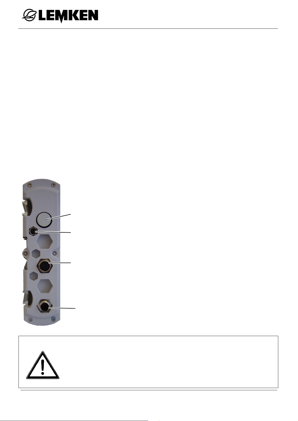
The operating terminal has the following
connections:
Pressure compensation element [must
Pressure compensation
LIN OUT
not be opened]
LIN OUT [Output]
Signal socket
CAN
Signal socket
CAN
CAUTION
16
Never open the pressure compensation element
The pressure compensation element must never be opened.
Opening the pressure compensation element will cause severe or
irreparable damage to the operating terminal.
Page 17

Preparations on the tractor
The following cables can be connected to the signal socket:
Speed sensor set
Radar or universal joint adapter cable
5.3 Socket
A 3-pin socket according to DIN 9680 must
be available on the tractor for the power
supply.
If necessary, the optional battery connection cable can be connected directly to the
battery of the tractor.
5.4 Operating voltage and fuses
An operating voltage of 12 volts, with a tolerance range of between 10 and 15
volts is provided for the electronic control unit.
Voltage levels which are too low or too high will lead to malfunctions and may destroy the electronic equipment. In addition, the power supply must be provided
with at least a 25 A fuse.
The electronic control unit has an operating terminal and a job computer. The operating terminal must be installed in the cab of the tractor within reach and in view
of the driver. The job computer is located on the implement.
The operating terminal must be disconnected from the power supply:
after work with the implement is finished,
before the implement is parked for an extended period.
17
Page 18
Preparations on the operating terminal
6 PREPARATIONS ON THE OPERATING TERMINAL
6.1 Segment box
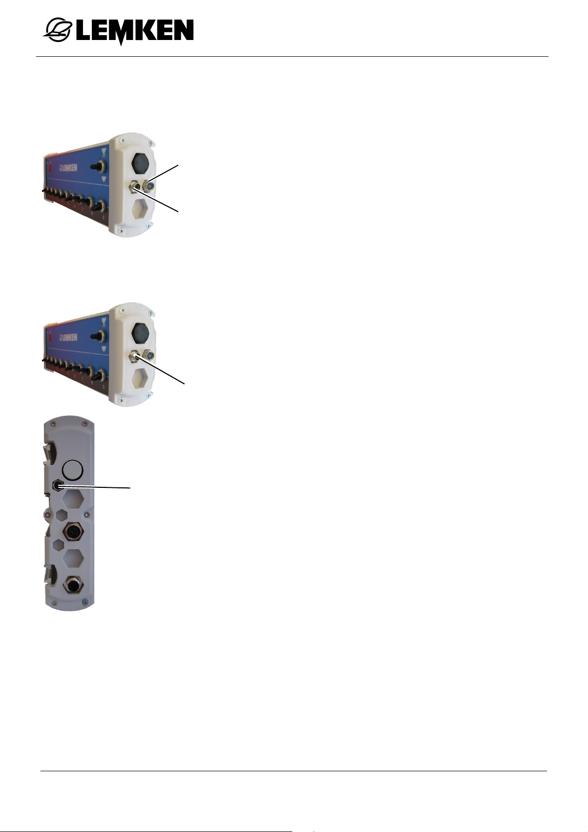
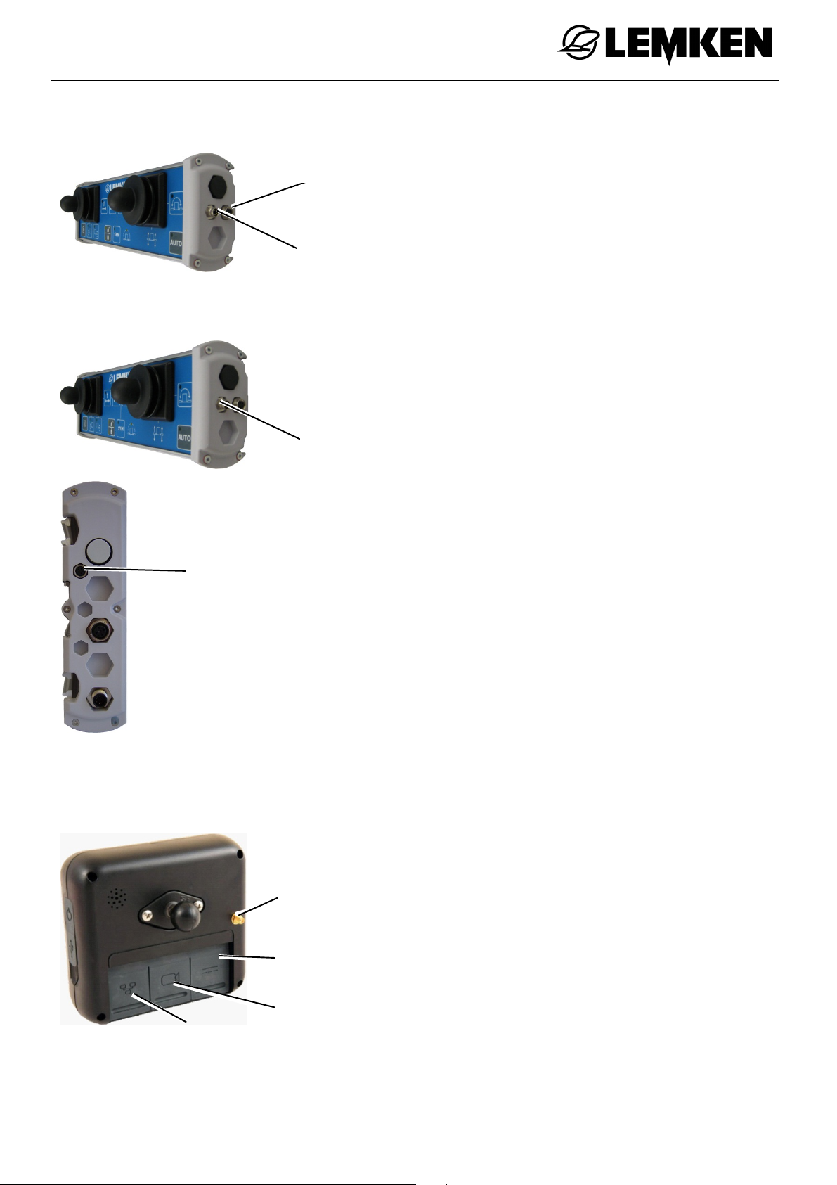
The segment box has the following con-
LIN OUT
nections:
LIN OUT [Output]
LIN IN
LIN IN [Input]
The segment box must be connected to the Ecospray operating terminal as follows:
Switch off the Ecospray operating termi-
nal.
Connect the cable to the LIN IN connec-
tion on the segment box.
LIN IN
Connect the cable to the LIN OUT con-
nection on the Ecospray operating ter-
LIN OUT
minal.
18
Page 19
Preparations on the operating terminal
6.2 Joystick box
LIN OUT
The joystick box has the following connections:
LIN OUT [Output]
LIN IN
LIN IN [Input]
The joystick box must be connected to the Ecospray operating terminal as follows:
Switch off the Ecospray operating termi-
nal.
Connect the cable to the LIN IN connec-
LIN IN
tion on the joystick box.
Connect the cable to the LIN OUT con-
nection on the Ecospray operating terminal.
LIN OUT
6.3 Matrix operating terminal
6.3.1 Connections
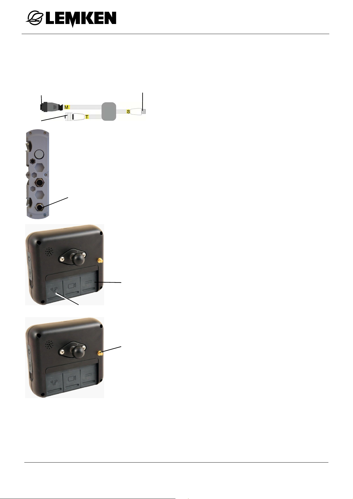
GPS antenna
Speed signal
Camera
CAN BUS/POWER
The matrix operating terminal has the following connections, amongst others:
GPS antenna
Speed signal
CAN BUS/POWER
Camera
19
Page 20
Preparations on the operating terminal
The matrix operating terminal must be connected to the job computer of the implement and the Ecospray operating terminal as follows:
Connection
Connection
CAN
Connection
Switch off the Ecospray operating termi-
nal.
Connect connection S of the cable to the
job computer of the implement.
Connect connection T of the cable to the
CAN connection on the Ecospray operating terminal.
Connect connection M of the cable to
the CAN BUS / POWER connection on
6.3.2
CAN BUS/POWER
Speed signal
GPS antenna
the matrix operating terminal.
Connect the GPS antenna to the GPS
antenna connection on the matrix operating terminal.
20
Page 21

Preparations on the operating terminal
6.3.3 Switching on the matrix operating terminal
The Ecospray operating terminal must be switched on before the
matrix operating terminal is switched on.
See the operating instructions for the matrix operating terminal.
6.3.4 Switching off the matrix operating terminal
The matrix operating terminal must always be switched off before
the Ecospray operating terminal is switched off.
Otherwise, loss of data may occur.
See the operating instructions for the matrix operating terminal.
21
Page 22
Ecospray operating terminal
7 ECOSPRAY OPERATING TERMINAL
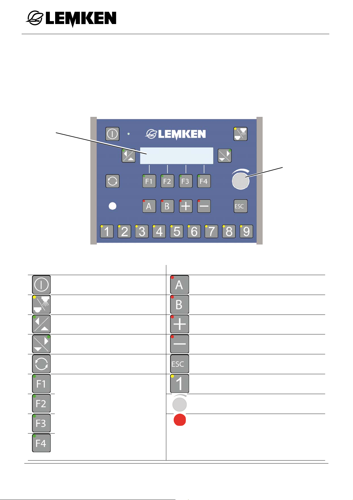
The operating terminal is used to operate the electronic control unit.
It is connected to the job computer on the implement and among other things,
consists of a display, keys, LED indicators and a rotary encoder.
7.1 Overview
Display
Rotary encoder
7.2 Function
Key Function Key Function
Operating terminal ON / OFF
Spray ON / OFF Freely programmable
Scroll left Increase quantity
Scroll right Reduce quantity
Switch between the last display and operating menu
Function keys F1 - F4:
Perform the function which is
graphically displayed / further
menu
Freely programmable
Emergency switch
Skip back
Cancel entry of value
1-9: Segment selection control
Select/scroll/enter/confirm/acknowledge
error
LED
indication of:
Information
Warnings
Alarms
22
Page 23

Ecospray operating terminal
7.3 Other displays
This display appears during a work step.
Press this key to interrupt the work step.
23
Page 24
Segment box
8 SEGMENT BOX
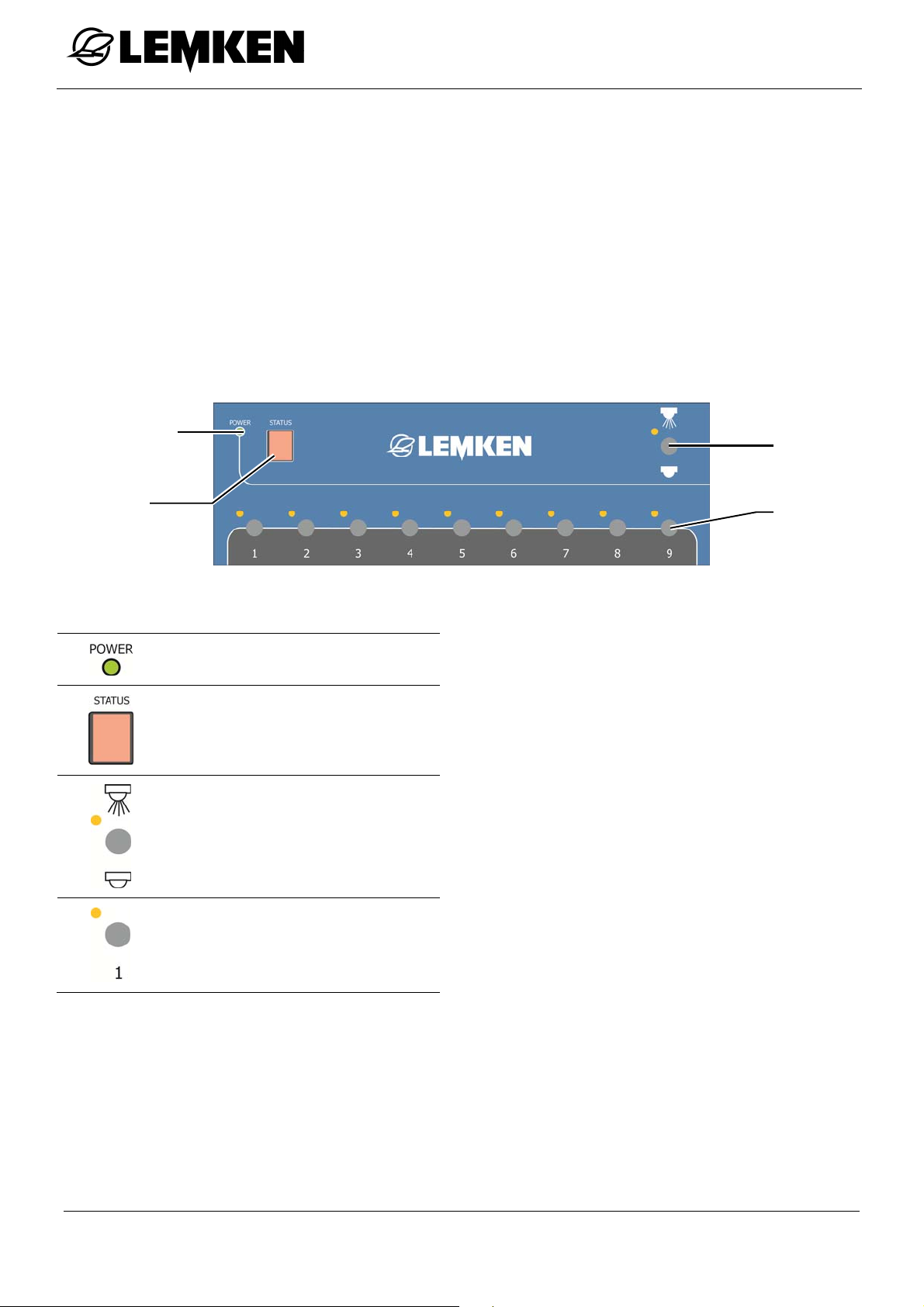
Switching of the segment box and the Spray ON/OFF function can be controlled
with the segment box.
It is connected to the operating terminal and among other things, consists of a
display, switches and LED indicators.
The segment box is connected with the LIN IN connection on the LIN connection
of the operating terminal or to the LIN OUT connection of the joystick box.
8.1 Overview
Spray ON /
OFF
Status
display
Key Function
LED
Status display
Spray ON / OFF
Segment
switch
Segment switch 1 - 9
8.2 Function
As soon as the segment box is connected to the operating terminal, keys 1 to 9 of
the segment switch on the operating terminal become inactive.
The function Spray ON/OFF can be controlled either on the operating terminal or
on the segment box.
24
Page 25
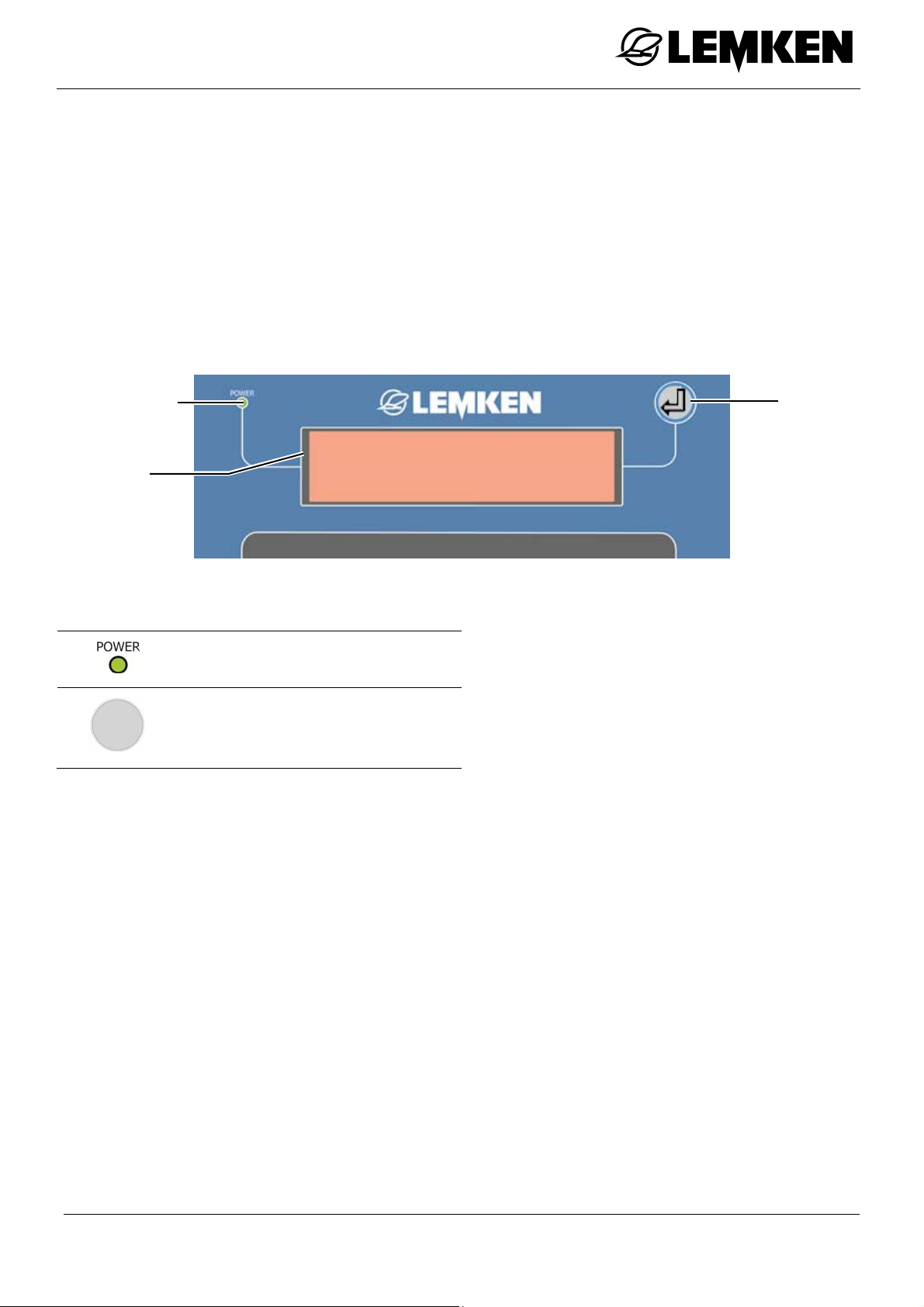
TankPilot electronic fill level indicator
9 TANKPILOT ELECTRONIC FILL LEVEL INDICATOR
The TankPilot electronic fill level indicator displays the fill level on the implement.
The TankPilot electronic fill level indicator is located on the implement control centre.
The TankPilot electronic fill level indicator is connected to the job computer on the
implement and consists, amongst other things, of a display, a button and an LED.
9.1 Overview
LED
Display
Key Function
LED
Acknowledge alarm
Button
25
Page 26

TankPilot electronic fill level indicator
9.2 Function
The TankPilot electronic fill level indicator can show the following displays:
Current fill level
Maximum fill level alarm
Minimum fill level alarm
Selector valve position (option)
An alarm is displayed when the fill level specified on the operating terminal for that
alarm is reached. The alarm is displayed on the operating terminal and on the
TankPilot electronic fill level indicator display.
To acknowledge an alarm on the TankPilot
electronic fill level indicator display:
press the button.
To acknowledge an alarm on the operating
terminal:
press the rotary encoder.
26
Page 27
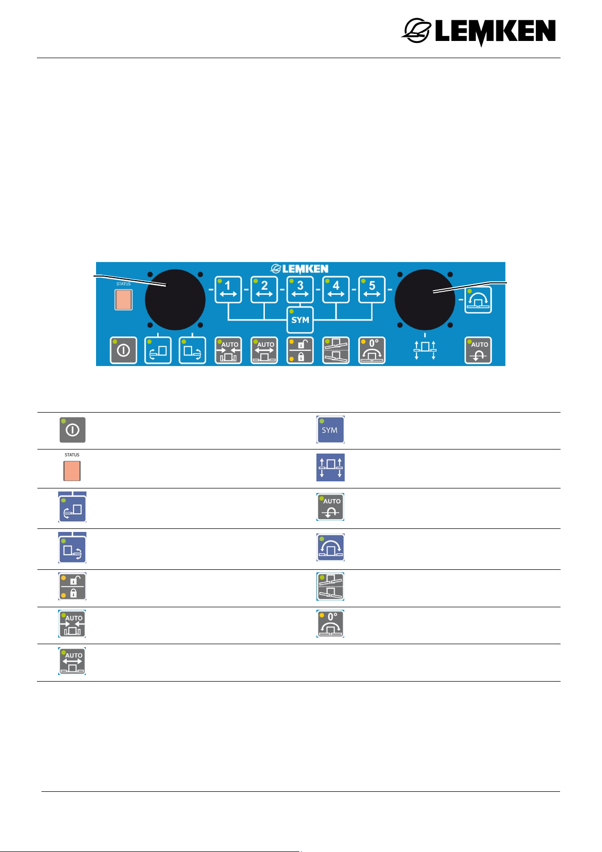
Joystick box
10 JOYSTICK BOX
If the implement is equipped with EcoControl, the boom can be completely controlled with the joystick box.
The joystick box is connected with the LIN IN connection on the LIN connection of
the operating terminal or to the LIN OUT connection of the segment box.
The active functions of the keys are shown by the LED indicators.
10.1 Overview
Joystick
left
Key Function Key Function
Joystick box ON / OFF
Status display;
also shows error messages
Boom pivoting - left
Boom pivoting - right
Preselect symmetrical folding
Raise and lower boom
Freely programmable;
Spray ON / OFF function
Slope compensator
Joystick
right
Open/Close swing lock
Automatic folding in
Automatic folding out
Slope mirroring
Middle of slope
27
Page 28
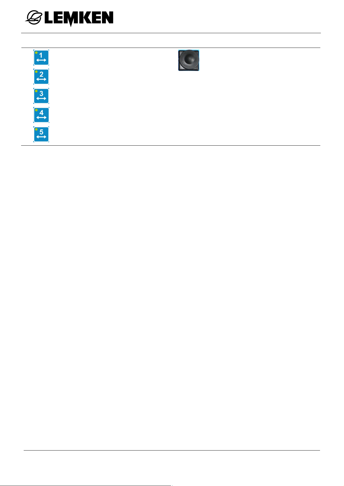
Joystick box
Selection of arm 1 to 5
Joystick
If the pre-selection of symmetrical
folding is not active:
Joystick left = Boom left
Joystick right = Boom
right
10.2 Function
The boom can be controlled with the joystick box as soon as the joystick box is
connected to the Ecospray operating terminal:
Raise and lower boom
Fold boom in and out
Boom pivoting for arm 1 left and right
Open/Close swing lock
Slope compensator
28
Page 29
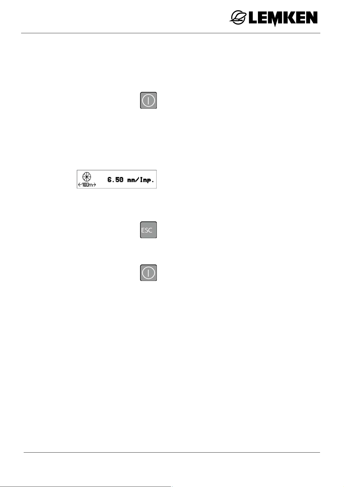
Commissioning
11 COMMISSIONING
11.1 Switching the operating terminal on and off
11.1.1 Switching on
Press this key to switch on the operating
terminal.
A brief system check is carried out, in
which all LEDs on the keys and all other
LEDs illuminate.
11.1.2 Switching off
The software version is then displayed.
Shortly after this, the current pulse number
is displayed.
The displays following switching on can
also be skipped directly:
Press this key.
Press this key for about 3 seconds to
switch off the operating terminal.
29
Page 30
Commissioning
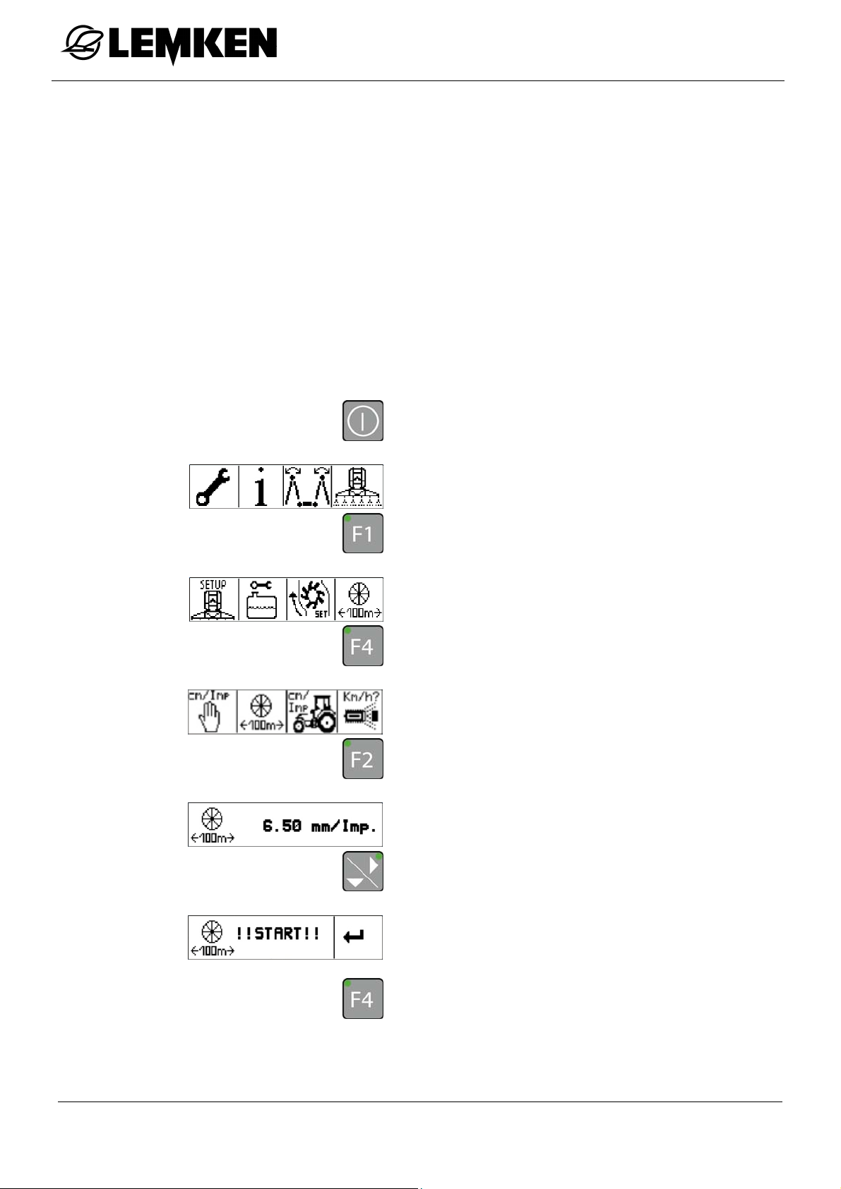
11.2 100 m calibration
A calibration over 100 m must be performed after the operating terminal is connected.
If possible, the 100 m calibration must be performed
on the area which is to be sprayed
with the four-wheel drive [if fitted] switched on
with the tank half full
with the specified air pressure in the tractor tyres
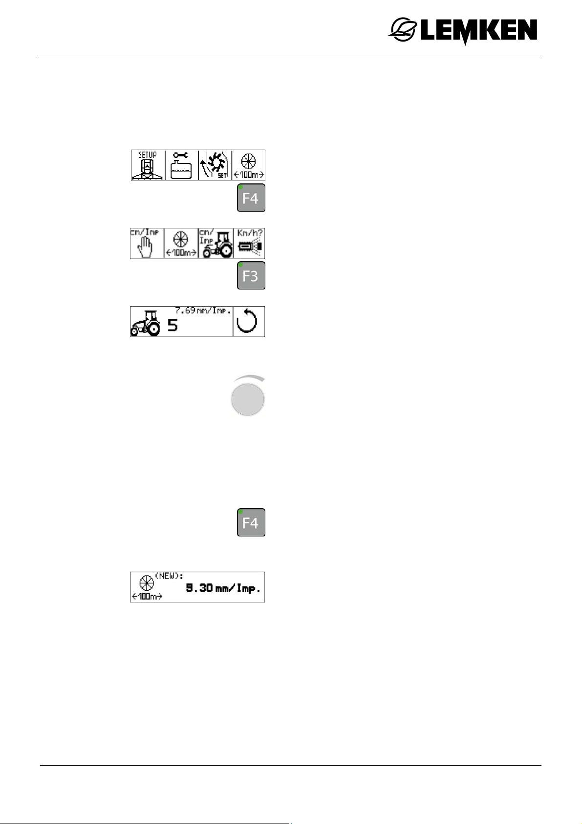
Press this key to switch on the operating
terminal.
The first basic menu is displayed.
Press this key to access the settings
menu.
The first settings menu is displayed.
Press this key to access the calibration
menu.
The calibration menu is displayed.
Press this key to access the 100 m cali-
bration menu.
The current pulse number is displayed.
Press this key to access the starting dis-
play for the 100 m calibration.
The 100 m calibration start display appears.
Press this key to start the 100 m calibra-
tion.
30
Page 31
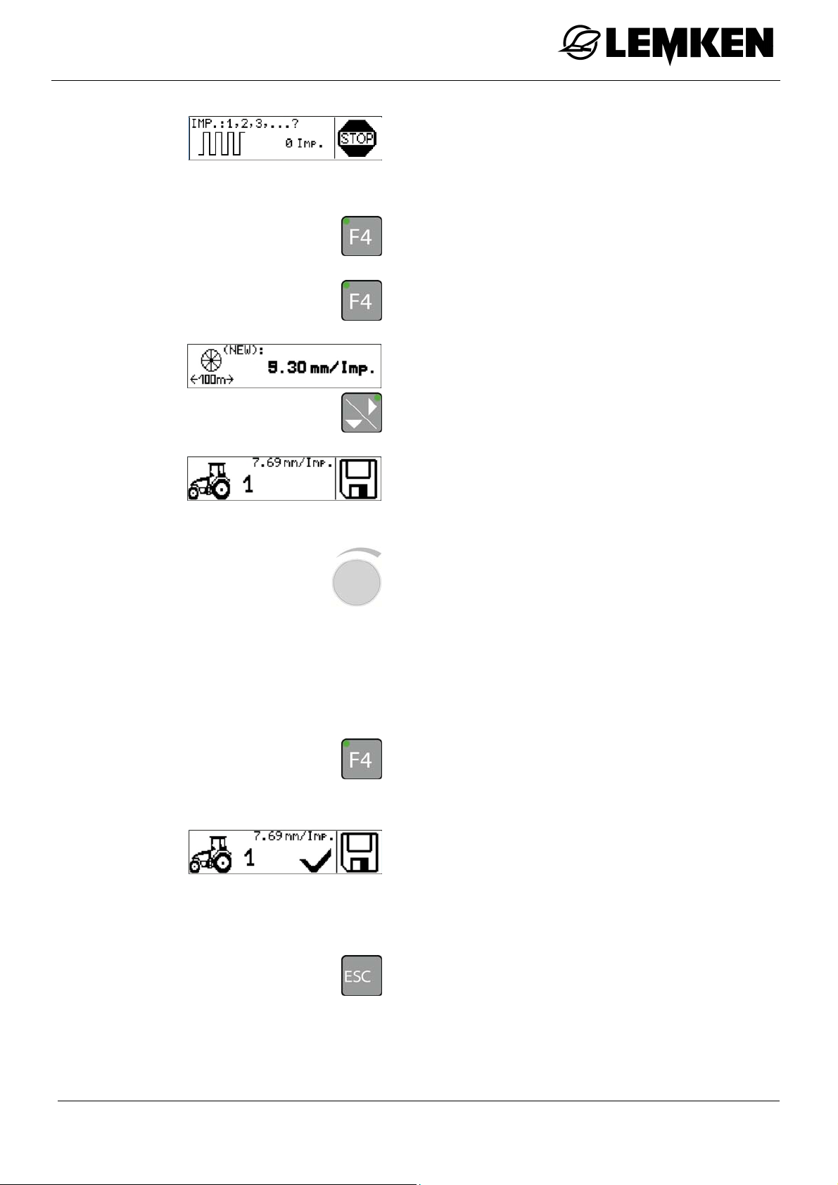
Commissioning
The 100 m calibration running display appears.
Drive a distance of 100 m.
Press this key to stop the 100 m calibra-
tion.
Press this key to confirm the 100 m cali-
bration.
The pulse number is displayed.
Press this key to assign the new pulse
number to a tractor.
The numbers 1 to 5 designate five possible
tractors. The pulse values for up to five
tractors can be saved and called up.
Press the rotary encoder to select the
tractor.
Turn the rotary encoder to enter the trac-
tor.
Press the rotary encoder to confirm the
tractor.
Press this key for about 2 seconds to
assign the number to the selected trac-
tor.
A tick now appears in the display.
The 100 m calibration is now complete for
this tractor. A calibration over 100 m must
be performed for every other tractor.
Press this key to return to the higher-
level menu.
31
Page 32
Commissioning
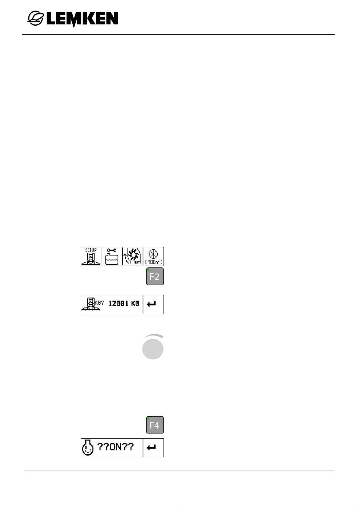
11.3 Calibration of flow meter
A calibration of the flow meter must be carried out before the start of each season.
To determine the weight of the combination of the tractor and the implement,
fill the tank of the implement with water
to the nominal fill level.
Drive with the implement onto a level,
unsurfaced area, where the water can
easily soak away.
Switch on the PTO.
Carry out spraying until water emerges
from all nozzles.
Weigh the combination of the tractor and
the implement.
From the settings menu
press this key to access the implement
weight menu.
The display for entering the weight of the
combination of tractor and implement appears.
Press the rotary encoder to select the
value.
Turn the rotary encoder to enter the val-
ue.
Press the rotary encoder to save the
value.
Press this key to confirm the value.
Does the 'Pump switched on' display appear?
32
Page 33
Commissioning
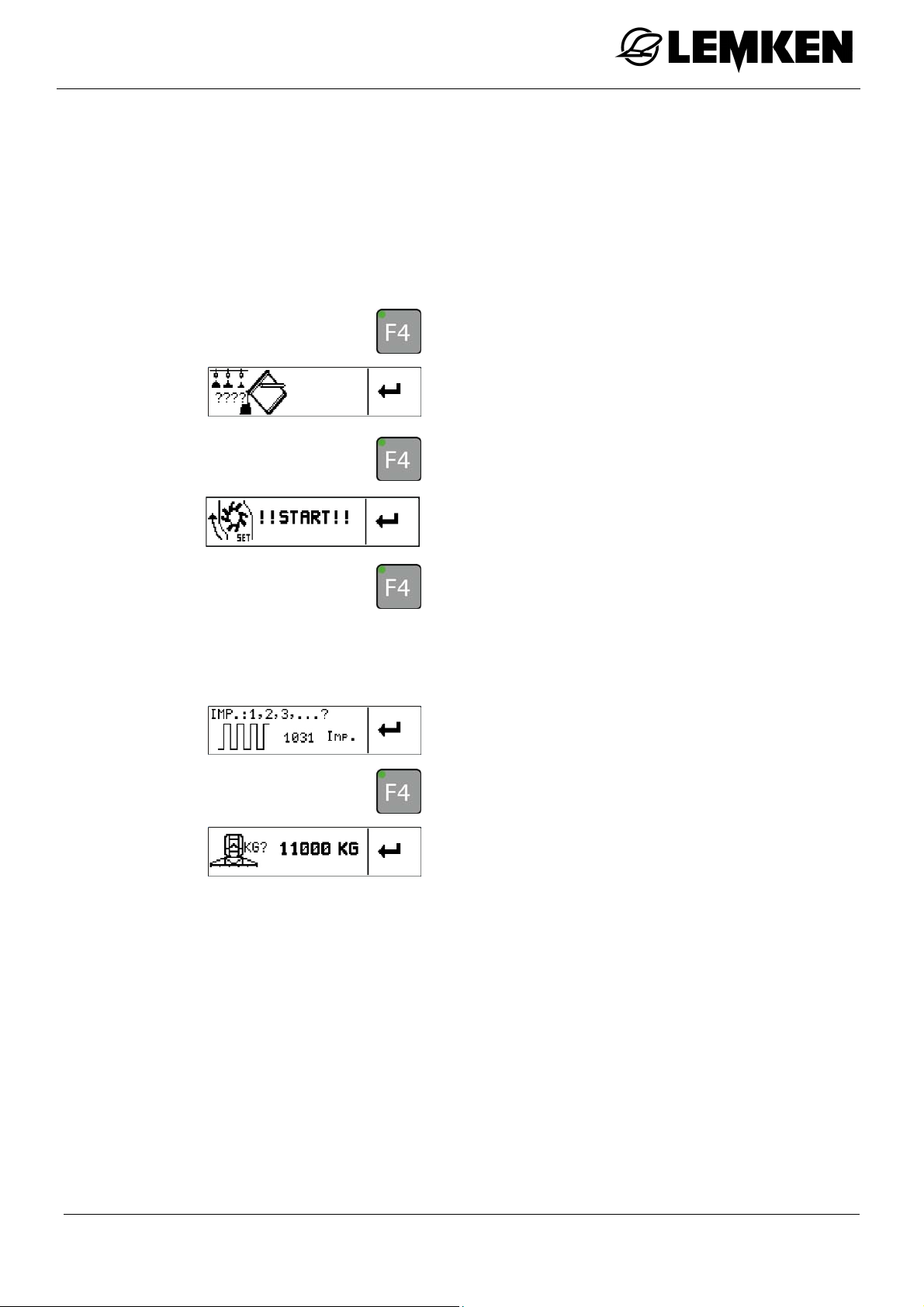
If not,
switch on the PTO.
Allow the pump to run at the specified
nominal speed. Refer to the operating
instructions for the implement.
Press this key to confirm the process.
The display that the nozzles are filled ap-
pears.
Press this key to confirm the process.
The display for the start of calibration appears
Press this key to start calibration.
Carry out the calibration until the tank is
empty. See the fill level display on the
implement.
The pulses display appears.
Press this key to confirm the display.
The display of the empty weight appears.
Weigh the combination of the tractor and
the implement.
33
Page 34

Commissioning
Enter the weighed empty weight:
Press the rotary encoder to select the
value.
Turn the rotary encoder to enter the val-
ue.
Press the rotary encoder to save the
value.
Press this key to confirm the display.
The display of the new pulse number
appears.
Calibration of the flow meter is now com-
plete.
34
Page 35
Commissioning
11.4 Selection of saved pulse numbers for each tractor
According to the tractor, the required pulse number can be called up and set as
follows.
From the settings menu
press this key to access the calibration
menu.
The calibration menu is displayed.
Press this key to access the tractor se-
lection display.
The numbers 1 to 5 designate five possible
tractors with the allocated pulse counter.
To select the tractor:
Press the rotary encoder to select the
tractor.
Press the rotary encoder to enter the
tractor.
Press the rotary encoder to confirm the
tractor.
Press this key for about 2 seconds to
assign the number to the selected trac-
tor.
The saved pulse number is displayed.
35
Page 36

11.5 Target quantity
After the 100 m calibration, the target quantity in l/ha must be set.
From the settings menu
Press this key to access the setup
menu.
The current target quantity is displayed.
Press the rotary encoder to select the
number.
The target quantity can be set between 30
and 3,000 l/ha.
Commissioning
Turn the rotary encoder to enter the
number.
Press the rotary encoder to enter the
number.
36
Page 37
SEH Boom
12 SEH BOOM
12.1 General
Partially folding the individual arms of the boom in or out is not
permitted. The individual arms must always be folded completely
in or out.
The boom may only be folded when stationary.
Operation of the implement with the boom completely folded out
or symmetrically folded is not permitted if the swing lock/locking is
engaged.
Symmetrical vertical folding in or out is only possible if:
the swing lock/locking is closed,
the boom is within the detection range of the height adjustment
sensor,
all arms are completely folded in,
the optional hydraulic slope compensation is in the middle posi-
tion.
Control of the arms is only possible if:
both arms 1 are folded fully down
the locking/swing lock is closed.
37
Page 38
SEH Boom
12.1.1 Operation
Folding in and out of the SEH Basic and Full booms is controlled via the operating
terminal and the control units of the tractor.
Folding in and out of the SEH Comfort and Premium booms is controlled via the
operating terminal or the joystick box.
Depending on the equipment of the implement, the boom can be folded in or out
symmetrically or asymmetrically.
12.1.2 Function
With the SEH Basic and Full booms, a function can be pre-selected using the
keys and controlled with the tractor control unit.
With the SEH Comfort and Premium booms, a function can be controlled with the
function keys of the operating terminal or via the joystick box.
To select a function via the joystick box:
Press one of the appropriate keys.
The LED on the corresponding key illuminates.
To deselect a function:
press the key again.
The LED on the corresponding key goes
out.
12.1.3 LED above the function key
As soon as a function has been selected with a function key, the LED for this key
illuminates. The key does not need to be held down.
38
Page 39
SEH Boom
12.1.4 Information in the display
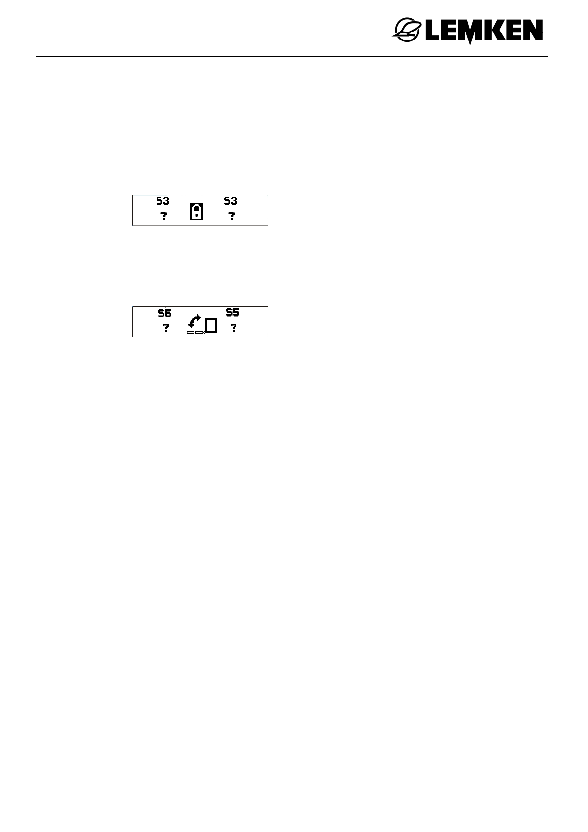
Ecospray operating terminal
If the relevant function key for the activation of a function is pressed and held and
one or more conditions for the activation of this function are not fulfilled, the corresponding information appears in the display.
Example
Joystick box
If a joystick is pressed and one or more conditions for the activation of this func-
tion are not fulfilled, the corresponding information appears in the display.
Example
39
Page 40

12.2 Versions
SEH booms are available in four different versions:
Basic
Full
Comfort
Premium
The following control units are required:
SEH Boom
Basic (*) ew dw dw dw - Full (*) ew dw dw dw dw dw
Comfort (**) Joystick,
SEH
Premium (**) Joystick,
Height adjustment
Joystick,
right and
left
right and
left
right and
Joystick,
right and
Folding, asymmet-
rical
left
left
Folding, symmetri-
cal
Joystick,
right and
left
Joystick,
right and
left
Swing lock
Joystick
box
Joystick
box
Slope compensati-
on
Joystick,
right and
left
Joystick,
right and
left
Pivoting the booms
Joystick,
left
Joystick,
left
(*) only in association with Closed Center hydraulic system
(*) only in association with Open Center hydraulic system or load-sensing hydrau-
lic system
ew = single-acting tractor control unit
dw = double-acting tractor control unit
symmetrically /
asymmetrically
40
Page 41
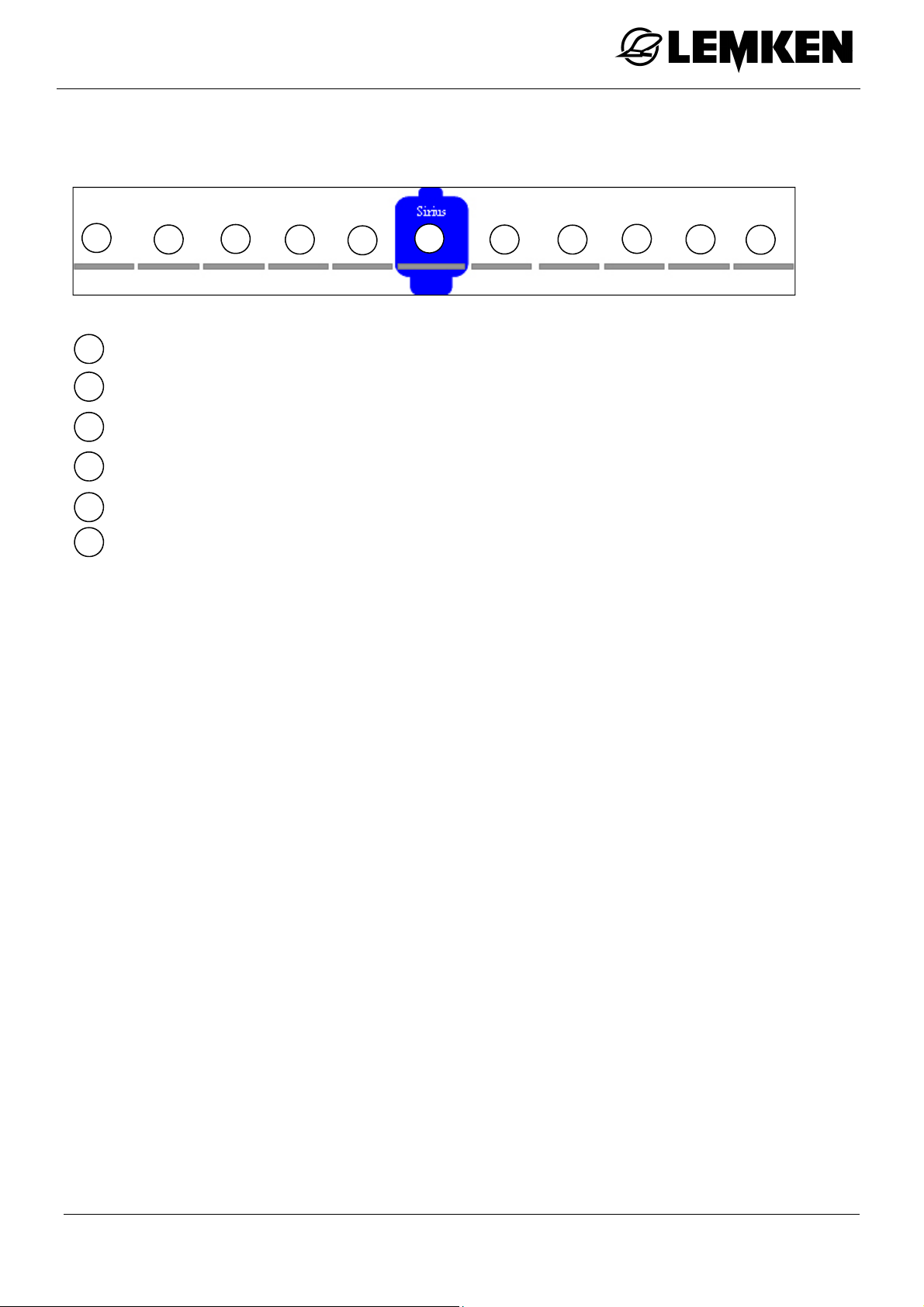
SEH Boom
12.3 Boom distribution
5
0
1
2
3
4
5
4
= Arm 0
= Arm 1
= Arm 2
= Arm 3
= Arm 4
= Arm 5
3
2
1
0
1
2
3
4
5
41
Page 42
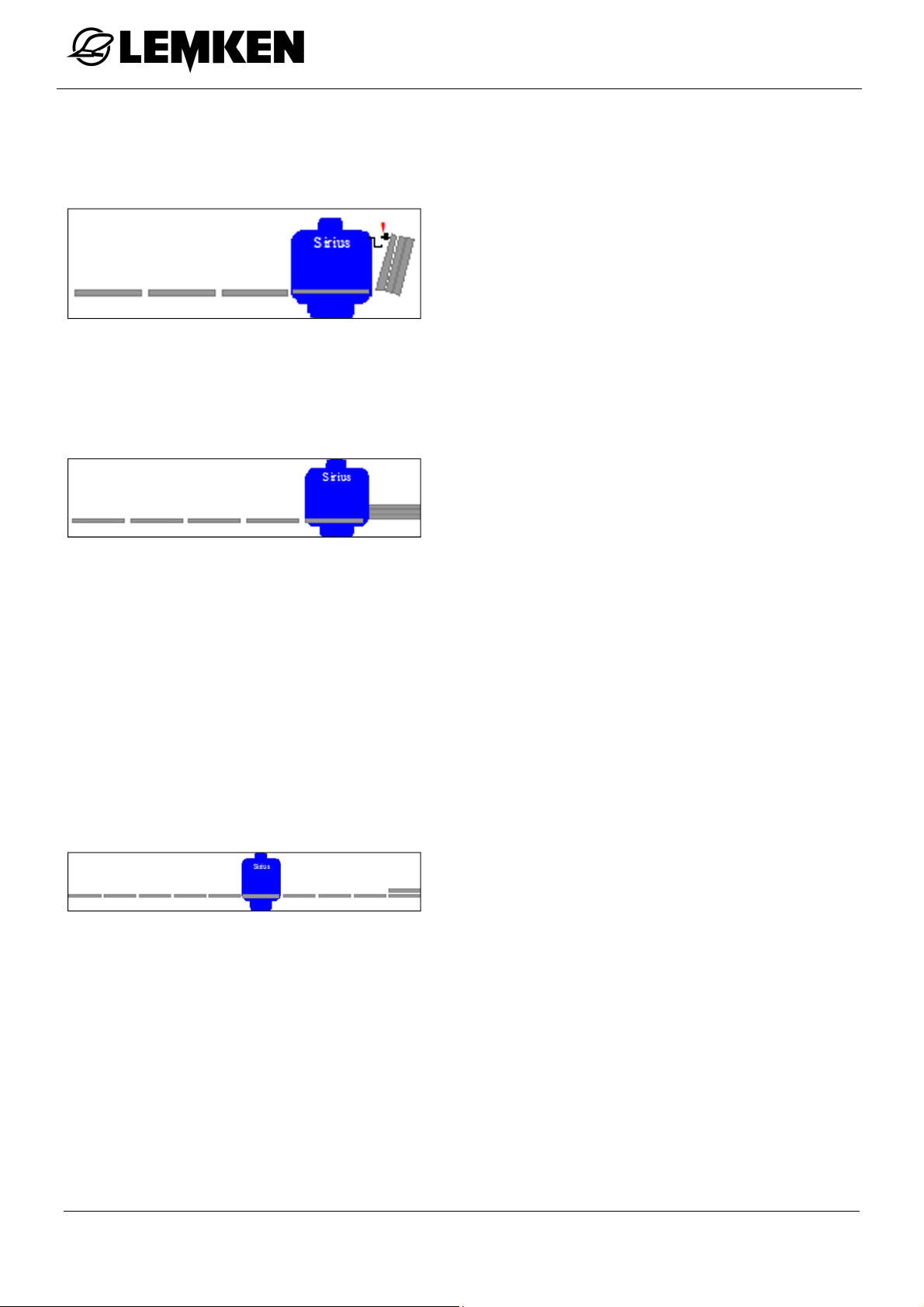
Permissible reduction of the working width
SEH 15 and 18
symmetrically with arms 3, 2 and 1.
one-sided on left with arms 3, 2 and 1.
one-sided on right with arms 3, 2 and 1.
all combinations between one-sided and
symmetrical.
SEH 20, 21 and 24
symmetrically with arms 4, 3, 2 and 1.
one-sided on left with arms 4, 3 and 2, if
SEH Boom
SEH 27, 28 and 30
arm 1(-4) is folded out on the right.
one-sided on right with arms 4, 3 and 2,
if arm 1(-4) is folded out on the left.
all combinations between symmetrical
and one-sided on the left and right.
symmetrically with arms 5, 4, 3 and 2.
Arm 5 asymmetrical, if arm 5 is folded
out on the opposite side.
42
Page 43
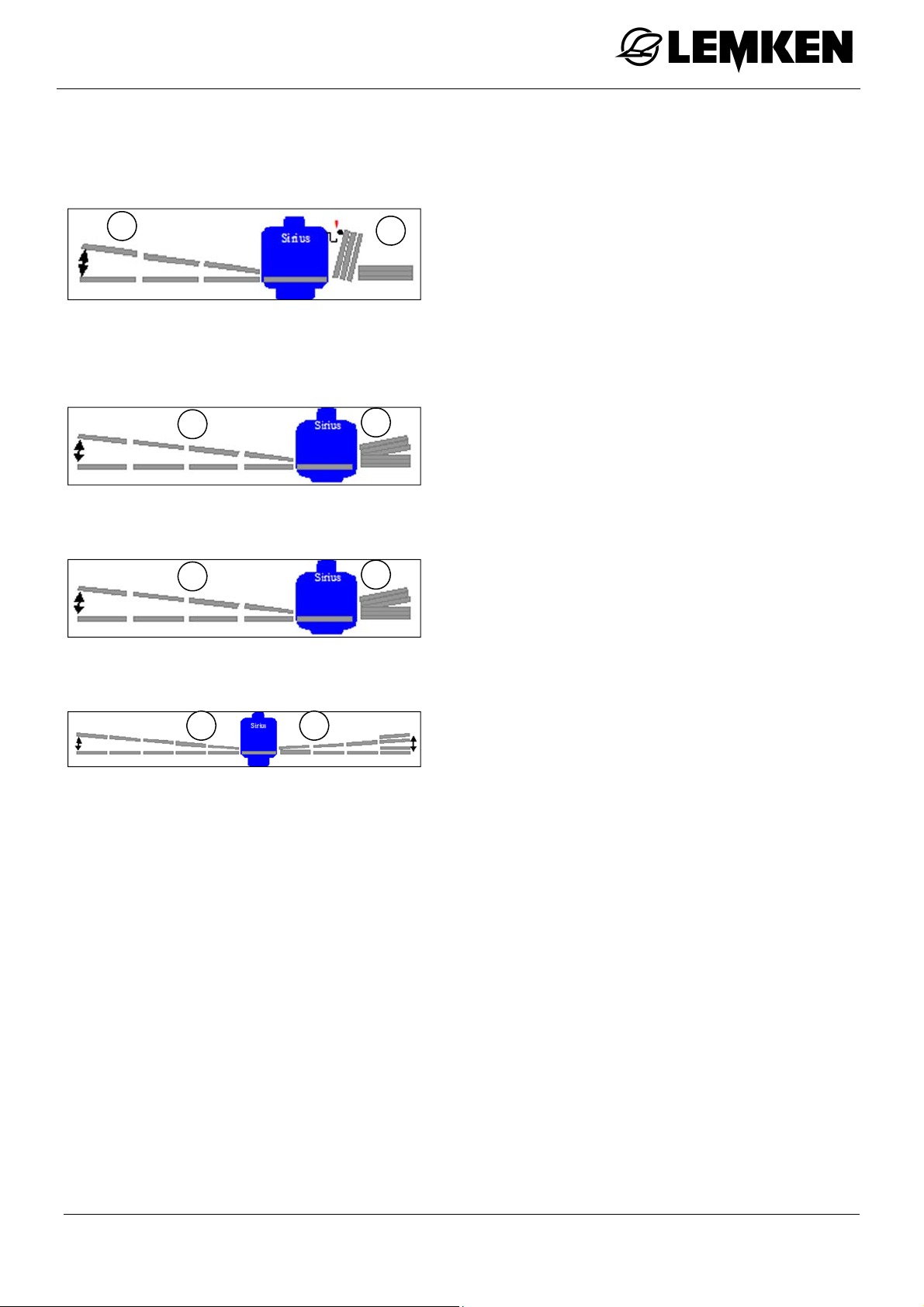
SEH Boom
Permissible pivoting of the arms
SEH 15 and 18
1
SEH 20 and 21
1
SEH 24
1
2
2
2
With arms folded out or reduced up to
20° (1).
With arms 1 (-3) folded in by up to 80°
(2).
With arms folded out or folded in up to
20° (1) and (2).
With arms folded out or folded in up to
17° (1) and (2).
SEH 27, 28 and 30
1 2
With arms 5 folded out or folded in up to
15° (1) and (2).
43
Page 44
12.4 SEH Basic boom
12.4.1 General
SEH Boom
Press this key to switch on the operating
terminal.
Before the boom can be folded out:
Lift the boom up to the detection position
using the control unit.
To fold out the booms:
Press this key to access the first folding
menu.
The first folding menu is displayed.
Here, the following functions can be controlled:
Swing lock
Symmetrical folding of the boom
44
Page 45
SEH Boom
12.4.2 Swing lock
Press one of the keys to pre-select the
or
swing lock function.
Use the relevant control unit on the trac-
tor to open or close the swing lock.
Press one of the keys to cancel the pre-
or
selection.
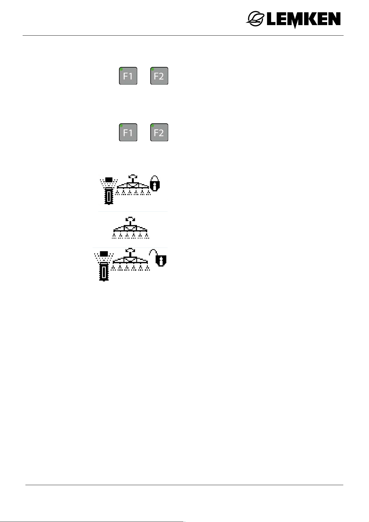
The following displays indicate the status of the swing lock:
Swing lock closed
Swing lock neither completely open nor
completely closed
Swing lock open
45
Page 46
12.4.3 Folding the boom out symmetrically
Lift the boom using the appropriate con-
trol unit until the folding position is
reached.
The display for closing the swing lock now
appears.
Close the swing lock, see »Swing lock,
page 45«
Press this key from the folding menu to
select the function for folding out the
boom symmetrically.
SEH Boom
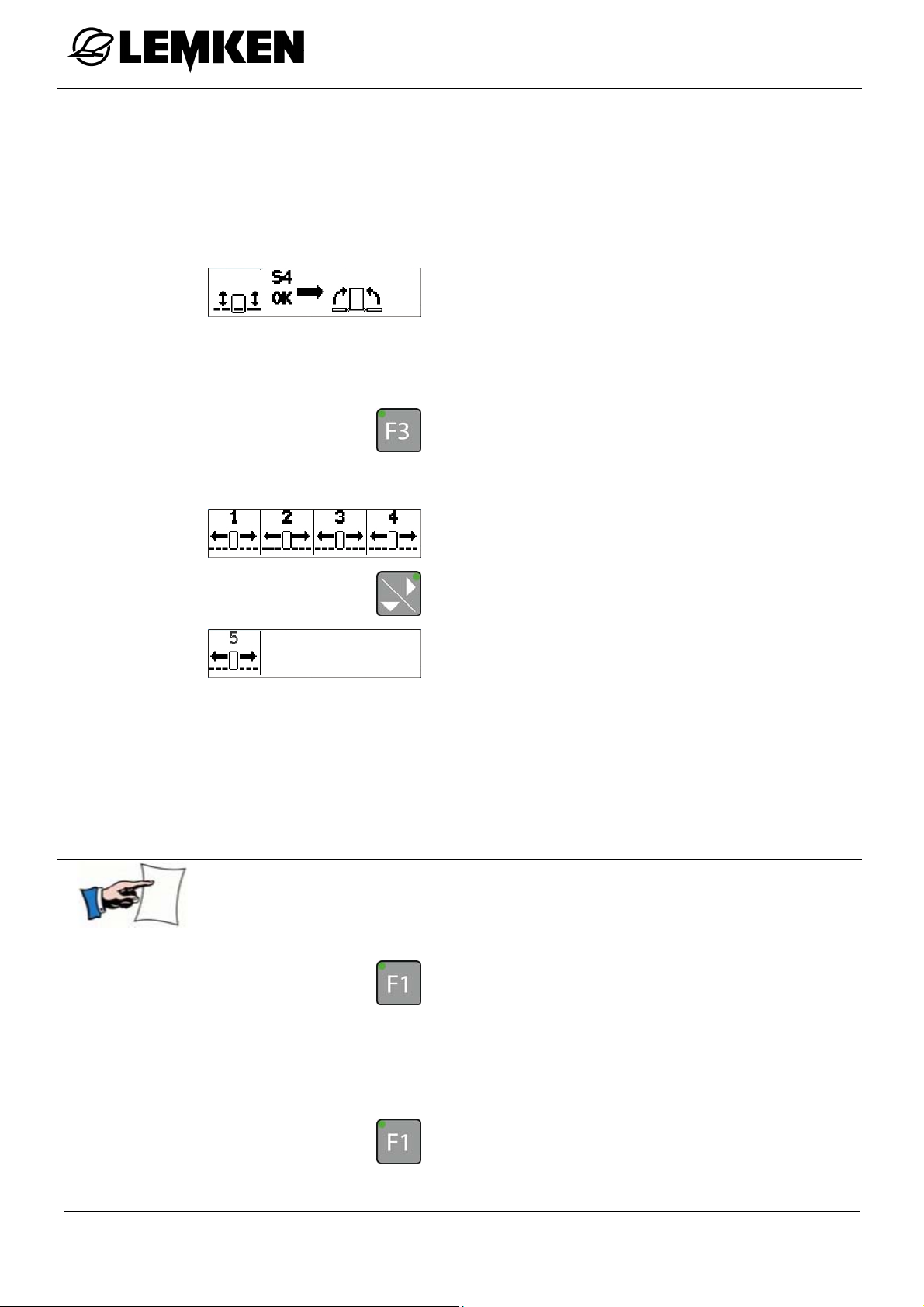
The menu for folding out the boom symmetrically appears. The boom can be folded out symmetrically in the following sequence:
Arm 1
Arm 2
Arm 3
Arm 4
Arm 5
Press the appropriate function key to pre-select an arm.
Hold the key down. Any information will be displayed.
Press this key to pre-select arm 1.
To fold out arm 1:
use the appropriate control unit on the
tractor.
Press this key or another function key to
cancel the pre-selection.
46
Page 47

SEH Boom
Press this key to pre-select arm 2.
To fold out arm 2:
use the appropriate control unit on the
tractor.
Press this key or another function key to
cancel the pre-selection.
To pre-select arms 3, 4 or 5,
press the appropriate function key.
To fold out arms 3, 4 or 5:
use the appropriate control unit on the
tractor.
Press this key or another function key to
cancel the pre-selection.
As soon as all booms are folded out,
open the swing lock.
47
Page 48
12.4.4 Folding the boom in symmetrically
Press this key in the folding menu to fold in
the boom symmetrically.
Close the swing lock.
Bring the boom into the detection posi-
tion.
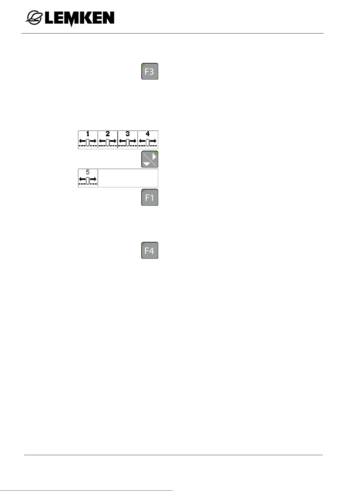
The menu for folding the boom symmetri-
cally appears.
SEH Boom
Press this key in the second window to
pre-select arm 5.
Use the relevant control unit to fold in
the arm.
Press this key to pre-select arm 4.
Use the relevant control unit to fold in
the arm.
To pre-select arms 3, 2 or 1,
press the appropriate function keys.
Hold this key down. Any information will
be displayed.
To fold in arms 3, 2 or 1:
use the appropriate control unit on the
tractor.
Press a function key to cancel the pre-
selection.
Lower the boom using the appropriate
control unit until the transport position is
reached.
48
Page 49
SEH Boom
12.5 SEH Full booms
12.5.1 General
Press this key to switch on the operating
terminal.
Before the boom can be folded out:
lift the boom up to the detection position
using the control unit.
To fold out the boom:
press this key to access the first folding
menu.
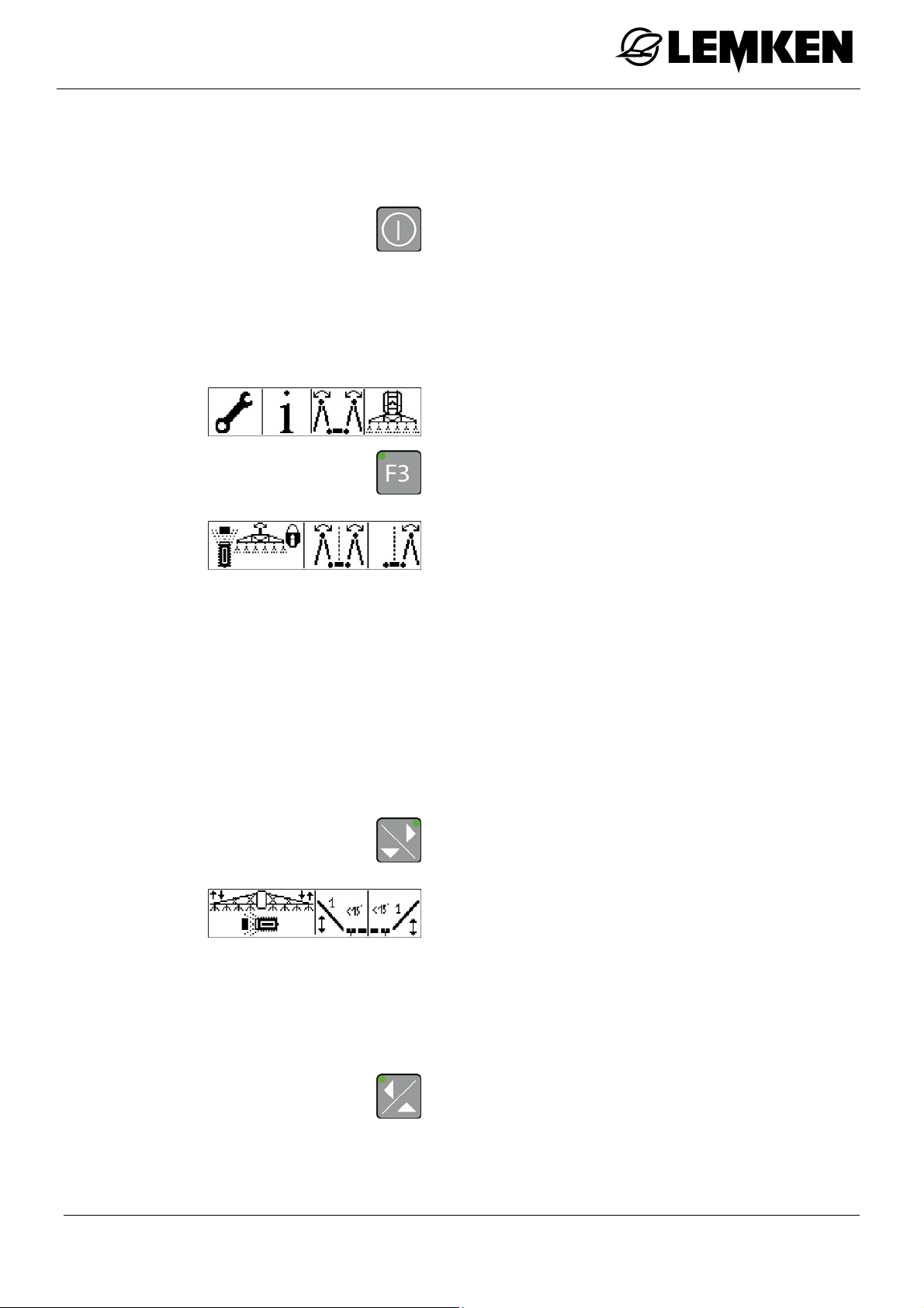
The first folding menu is displayed.
Here, the following functions can be controlled:
Swing lock
Symmetrical folding of the boom
Asymmetrical folding of the boom
Close the swing lock. See »Swing lock,
page 45«.
Press the key to access the second fold-
ing menu.
The second folding menu is displayed.
The following functions can be controlled in
the second folding menu:
Slope compensator
Pivoting of arm 1 on one or both sides
Press this key to return to the first folding
menu.
The swing lock must be opened again after
the boom is folded out.
49
Page 50
12.5.2 Folding the boom out symmetrically
Before the boom can be folded out:
lift the boom up to the detection position
using the control unit.
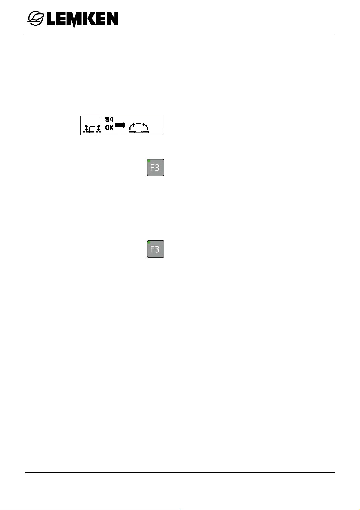
The display for closing the swing lock now
appears.
Close the swing lock.
Press the key in the first folding menu to
select the function for folding the boom
symmetrically. See »Folding out the
boom symmetrically, page 46«
SEH Boom
12.5.3 Folding the boom in symmetrically
Press the key in the first folding menu to
select the function for folding the boom
symmetrically. See »Folding in the boom
symmetrically, page 48«
50
Page 51
SEH Boom
12.5.4 Folding the boom in asymmetrically
Press this key in the first folding menu to
select the function for folding the boom
asymmetrically.
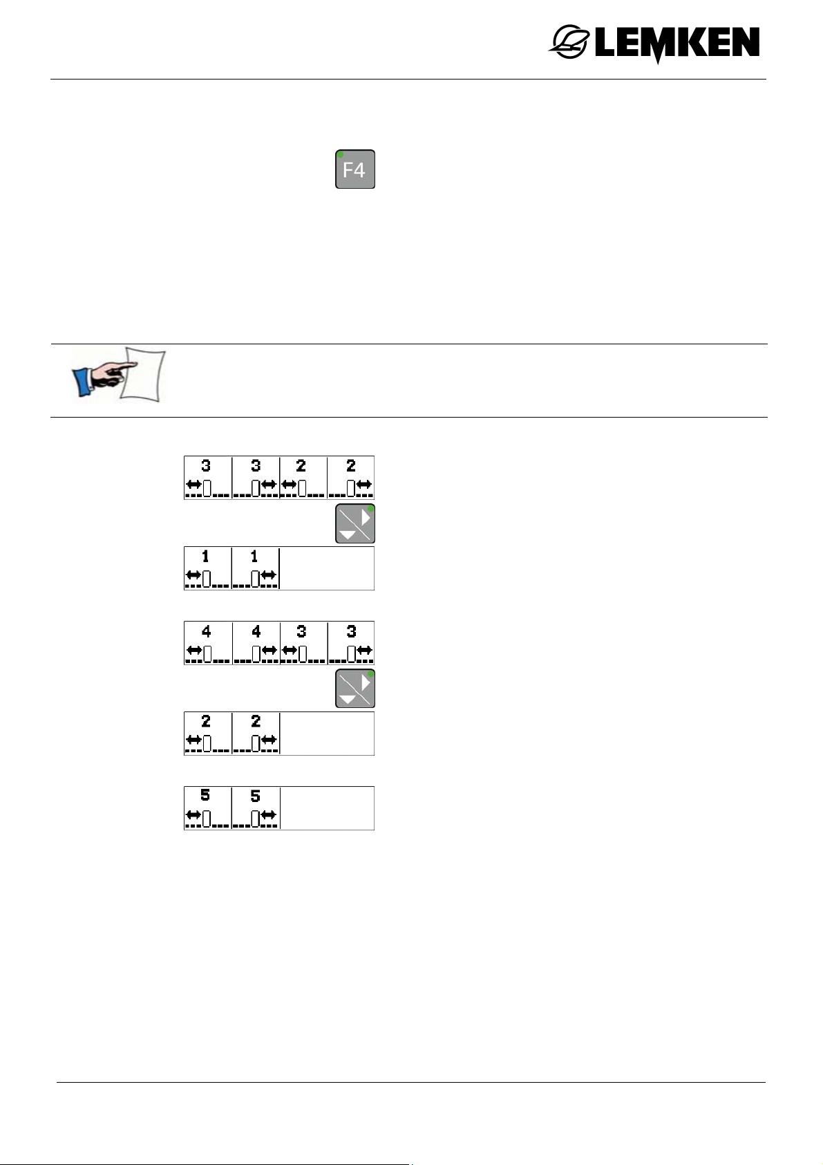
Depending on the version of the boom, the
first menu for folding the boom asymmetrically appears.
Press the appropriate function key to pre-select an arm.
Hold the key down. Any information will be displayed.
Version with 3 arms:
Version with 4 arms:
Version with 5 arms:
Use the tractor control unit to fold out the
arm.
12.5.5 Folding the boom out asymmetrically
To fold the boom out again, proceed in
the reverse sequence.
Once the boom is fully folded in,
lift the boom up to the detection position
using the control unit.
Close the swing lock.
51
Page 52
12.5.6 Slope compensator
SEH Boom
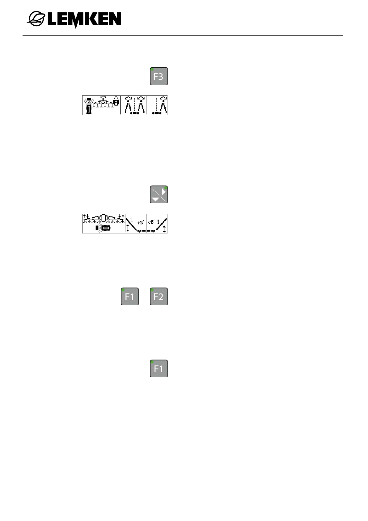
Press the key to access the first folding
menu.
The first folding menu is displayed.
Here, the following functions can be controlled:
Swing lock
Folding the boom out symmetrically
Folding the boom out asymmetrically
Press the key to access the second fold-
ing menu.
or
The second folding menu is displayed.
Here, the following functions can be con-
trolled.
Slope compensator
Pivoting of arm 1
Press one of the keys to pre-select the
slope compensator.
To set the slope compensation:
use the appropriate control unit on the
tractor.
Press the key or another function key to
cancel the pre-selection.
The slope compensation remains active
until
it is deselected or
another function is selected.
52
Page 53
SEH Boom
12.5.7 Pivoting of arm 1
This function enables pivoting of the arms, see page 43.
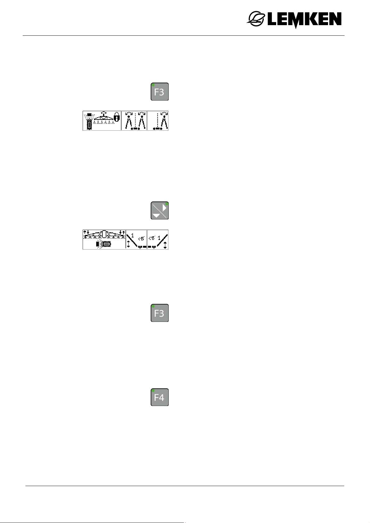
Press the key to access the first folding
menu.
The first folding menu is displayed.
Here, the following functions can be controlled:
Swing lock
Folding the boom out symmetrically
Folding the boom out asymmetrically
Press the key to access the second fold-
ing menu.
The second folding menu is displayed.
Here, the following functions can be controlled.
Slope compensator
Pivoting of arm 1 on one or both sides
Press the key to pre-select one-sided
pivoting of the left arm.
To adjust the one-sided pivoting of the left
arm:
use the appropriate control unit on the
tractor.
Press the key to pre-select one-sided
pivoting of the right arm.
To adjust the one-sided pivoting of the
right arm:
use the appropriate control unit on the
tractor.
53
Page 54

and
SEH Boom
Press both keys to pre-select the pivot-
ing of the arms on both sides.
To adjust the pivoting of the arms on both
sides:
use the appropriate control unit on the
tractor.
Press the key or another function key to
cancel the pre-selection.
54
Page 55
SEH Boom
12.6 SEH Comfort and Premium booms via the Ecospray operating terminal
12.6.1 General
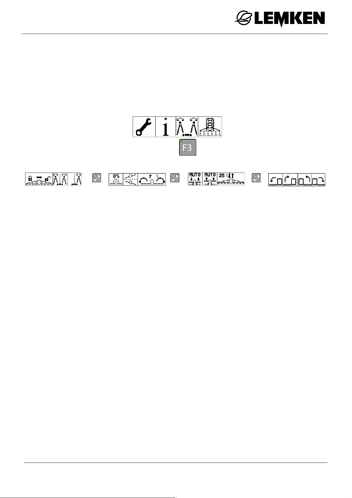
The folding menu for the SEH Comfort and Premium booms has the following
structure:
1. Folding menu 2. Folding
Activate swing lock
[F1/F2]
Fold the boom
symmetrically [F3]
Fold the boom
asymmetrically [F4]
menu
Move to middle of
slope [F1]
Slope mirroring
[F2]
Set slope com-
pensation manual-
3. Folding
menu
Boom height while
working [F1]
Boom height on
headland [F2]
Activate boom
manually [F3/F4]
4. Folding menu
Pivot the left arm
downwards [F1]
Pivot the left arm
upwards [F2]
Pivot the right
arm upwards
ly [F3/F4]
[F3]
Pivot the right
arm downwards
[F4]
55
Page 56
Press this key to switch on the operating
terminal.
Before the boom can be folded out:
pressurise the control unit of the tractor.
To fold out the boom:
Press this key to access the 1st folding
menu.
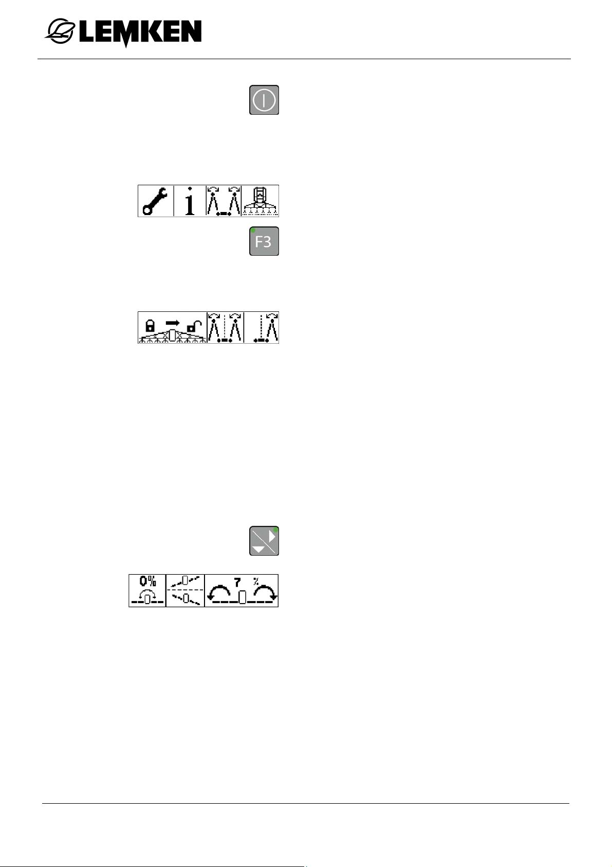
1. Folding menu – activate swing lock, fold boom
The first folding menu is displayed.
SEH Boom
2. Folding menu - slope activation
Here, the following functions can be controlled:
Close swing lock [F1]
Open swing lock [F2]
Fold the boom symmetrically [F3]
Fold the boom asymmetrically [F4]
Press the key to access the second fold-
ing menu.
The second folding menu is displayed.
The following functions can be controlled in
the second folding menu:
Move to middle of slope [F1]
Slope mirroring [F2]
Set slope compensation manually
[F3/F4]
56
Page 57
SEH Boom
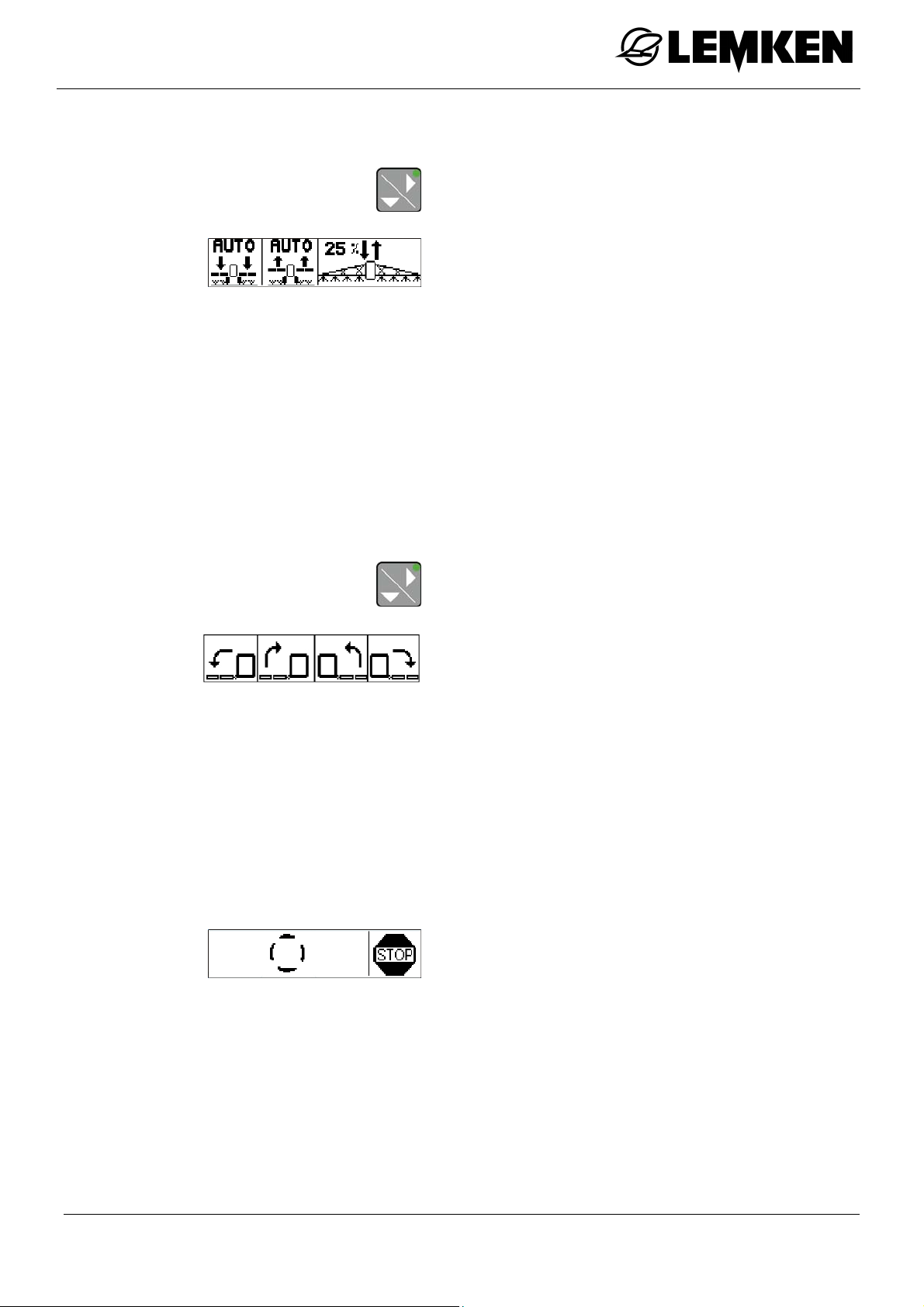
3. Folding menu - boom height
Press the key to access the third folding
menu.
The third folding menu is displayed.
Here, the following functions can be con-
trolled:
Boom height while working [F1]
Boom height on headland [F2]
Move the boom down manually [F3]
Move the boom up manually [F4]
4. Folding menu – pivoting the arms
Press the key to access the fourth fold-
ing menu.
The fourth folding menu for pivoting the
arms appears.
Here, the following functions can be controlled:
Pivot the left arm downwards [F1]
Pivot the left arm upwards [F2]
Pivot the right arm upwards [F3]
Pivot the right arm downwards [F4]
This display always appears while a work
step is being performed.
57
Page 58
12.6.2 Activating the swing lock
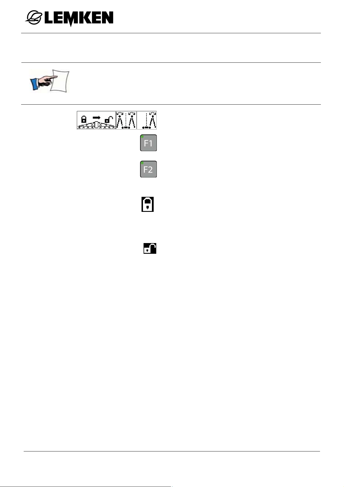
The swing lock must be closed before the boom is folded.
The swing lock must be opened again after the boom has been
fully folded out.
To close the swing lock:
Press this key from the first folding
menu.
Press this key to open the swing lock.
The following displays indicate the status of the swing lock:
SEH Boom
Swing lock closed
No symbol
Swing lock neither completely open nor
completely closed
Swing lock open
58
Page 59
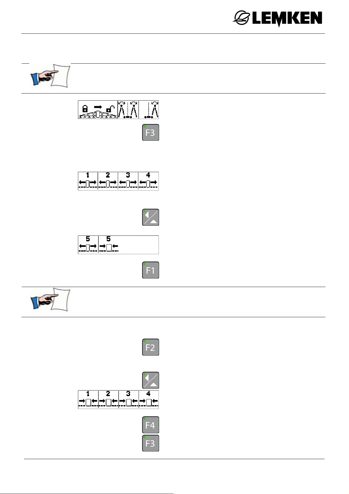
SEH Boom
12.6.3 Folding the boom in and out symmetrically (Comfort only)
Ensure that the swing lock is closed before folding out.
To fold out the boom symmetrically,
press this key.
Depending on the version, the menu for
folding the boom symmetrically appears.
Press the appropriate function key to
fold out the arm.
Press this key to display the selection for
arm 5 - if present.
The menu for folding arm 5 out and in is
displayed.
Press this key to fold out arm 5.
Ensure that the swing lock is open again after folding out the
boom.
To fold in arm 5 again:
press this key.
To fold in arms 4 to 1 again:
press this key.
The menu for folding in arms 1 to 4 is displayed.
Press this key to fold in arm 4
Press this key to fold in arm 3
59
Page 60
SEH Boom
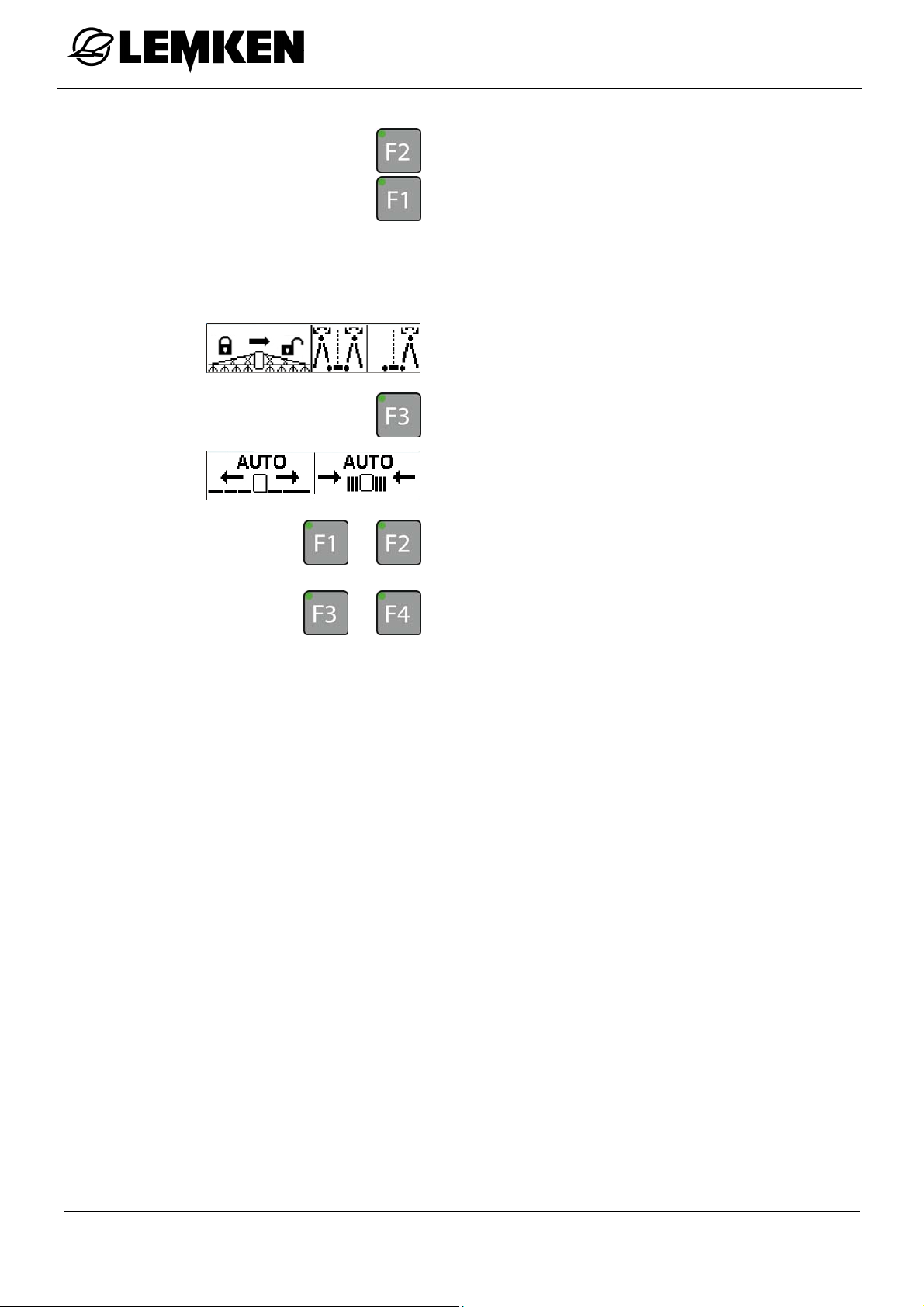
Press this key to fold in arm 2
Press this key to fold in arm 1
12.6.4 Automatically folding the boom in and out symmetrically (Premium
only)
To automatically fold the boom symmetrically,
press this key.
The menu for automatic folding is displayed.
Press one of these keys to fold out the
or
boom.
Press one of these keys to fold in the
or
boom.
Hold the key down until an acoustic sig-
nal indicates that the folding process is
complete.
60
Page 61
SEH Boom
12.6.5 Asymmetrical folding of the boom
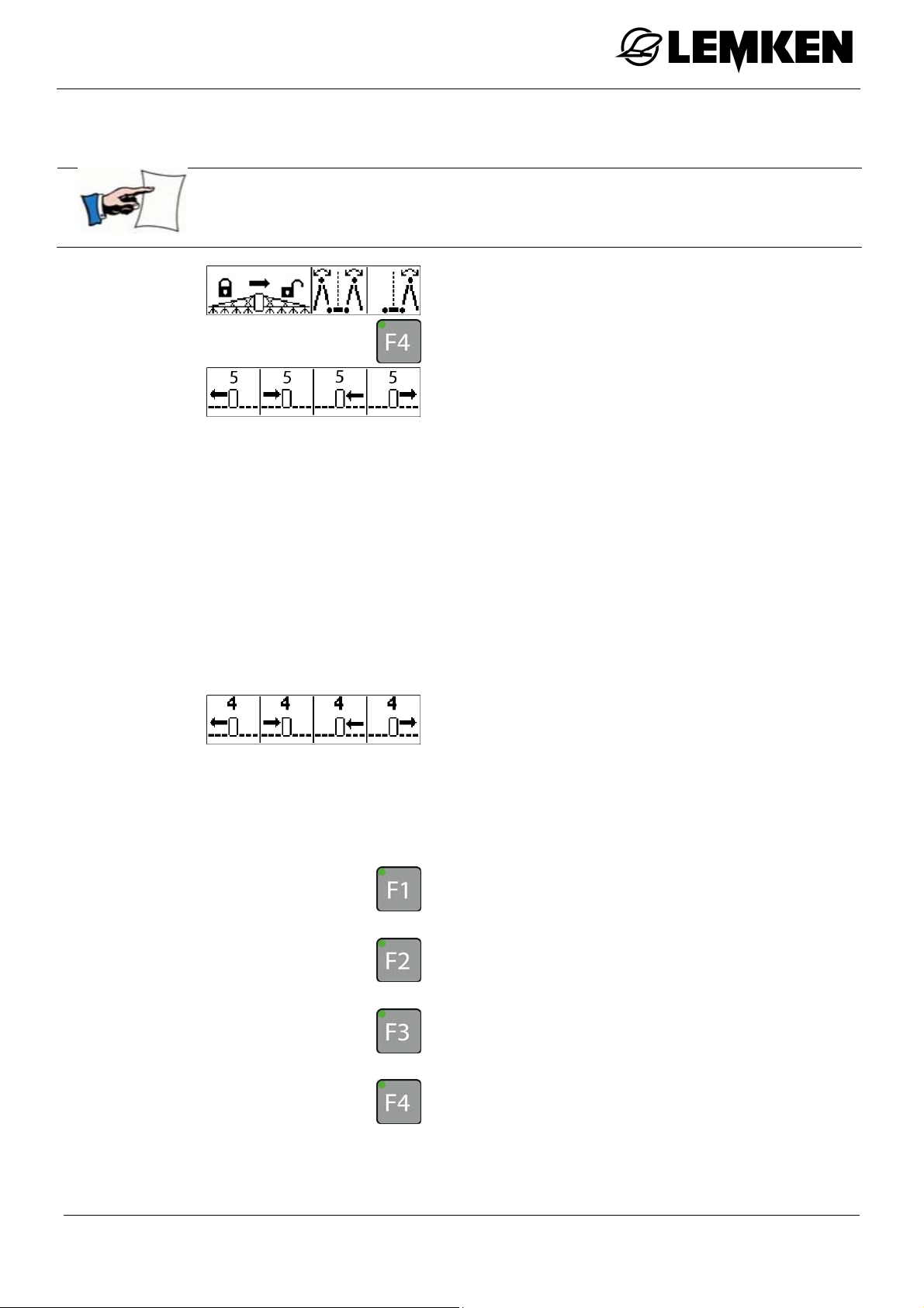
The arms can be folded out in pairs on both sides. For this, the
appropriate key must also be pressed.
To fold out the boom asymmetrically,
press this key.
The first menu for folding out the boom
asymmetrically appears.
(If a boom with 5 arms is fitted)
The following functions of the boom can be
controlled:
Arm 5 – fold out left
Arm 5 – fold in left
Arm 5 – fold in right
Arm 5 – fold out right
or
Arm 4 – fold out left
Arm 4 – fold in left
Arm 4 – fold in right
Arm 4 – fold out right
Press this key to fold out arm 5 or 4 on
the left.
Press this key to fold in arm 5 or 4 on
the left.
Press this key to fold in arm 5 or 4 on
the right.
Press this key to fold out arm 5 or 4 on
the right.
61
Page 62
12.6.6 Slope compensator
SEH Boom
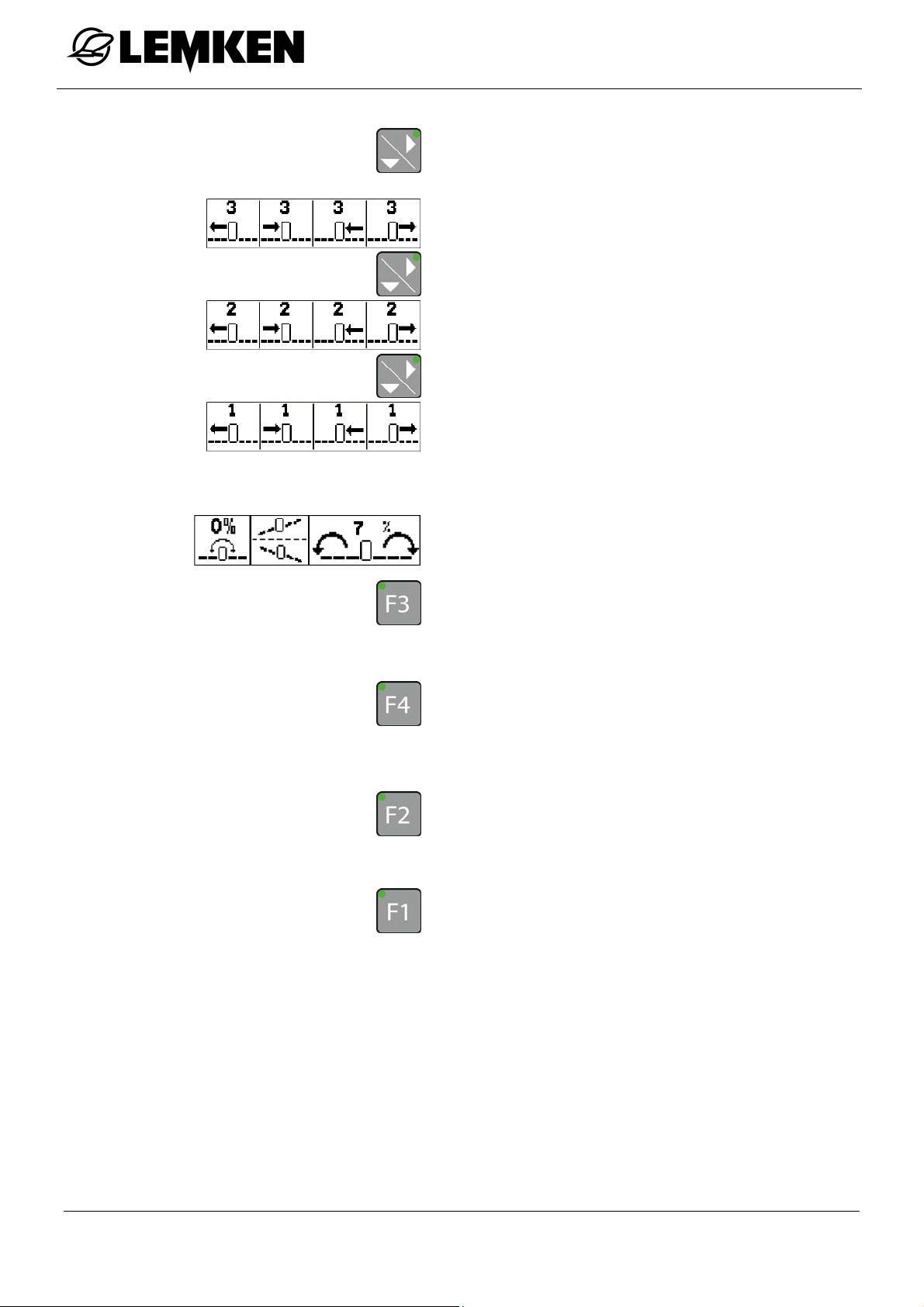
Press this key to access the menu for
folding the next arm asymmetrically.
To fold the corresponding arm:
proceed as described above.
To use any slope compensation:
Press this key in the second folding
menu and the boom will pivot down to
the left.
Press this key and the boom will pivot
down to the right.
To use a mirrored slope compensation:
press this key.
To move to the middle position:
press this key.
62
Page 63
SEH Boom
12.6.7 Move to the boom height
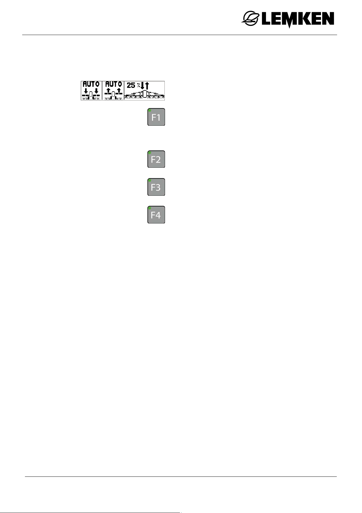
This function enables a pre-set boom height while working and at the headland.
The pre-set boom heights can be moved to
using the third folding menu.
Press this key to set the boom to the
pre-set working height.
Press this key to set the boom to the
pre-set height for the headland.
Press this key until the boom has moved
downwards to the required position.
Press this key until the boom has moved
upwards to the required position.
63
Page 64
12.6.8 Pivoting the arm
SEH Boom
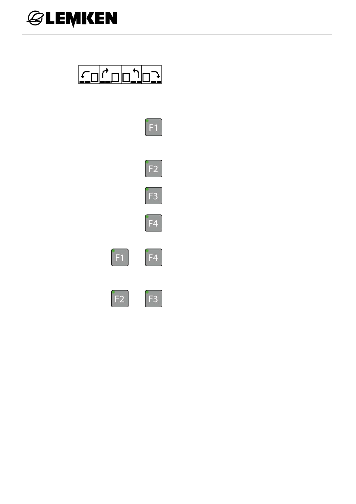
The arms can be pivoted on one side using
the fourth folding menu.
Fully fold out the boom. See »Folding
the boom, page 59«.
Press this key to move the left arm
downwards to the required position.
Press this key to move the left arm up-
wards to the required position.
Press this key to move the right arm
and
and
downwards to the required position.
Press this key to move the right arm up-
wards to the required position.
Press these keys to set pivoting of the
left and right arms downwards.
Press these keys to set pivoting of the
left and right arms upwards.
64
Page 65
SEH Boom
12.7 SEH Comfort and Premium booms via the joystick box
12.7.1 General
Before the boom can be folded out:
Press the key for about 1 second to
switch on the joystick box.
The boom automatically stops in the detec-
tion position.
12.7.2 Swing lock
The swing lock must be closed before the boom is folded out.
After the boom has been folded out, the swing lock must be
opened again (if this function is not activated automatically).
To open or close the swing lock:
Press this key to open or close the swing
lock.
When the swing lock is open, the upper
LED on the key illuminates.
When the swing lock is closed, the lower
LED on the key illuminates.
65
Page 66
12.7.3 Symmetrical folding of the boom
Press this key to select the function for
folding out the boom symmetrically.
The function is active as soon as the
LED illuminates.
Press this key to pre-select arm 1.
Press the left or right joystick outwards
to fold out arm 1.
Press this key to pre-select arm 2.
Press the left or right joystick outwards
to fold out arm 2.
SEH Boom
Press this key to pre-select arm 3.
Press the left or right joystick outwards
to fold out arm 3.
Press this key to pre-select arm 4.
Press the left or right joystick outwards
to fold out arm 4.
Press this key to pre-select arm 5.
Press the left or right joystick outwards
to fold out arm 5.
Press the relevant joystick inwards to
fold in the arms.
66
Page 67
SEH Boom
12.7.4 Asymmetrical folding of the boom
Press this key to deselect the function
for folding the boom symmetrically.
The function is inactive as soon as the
LED no longer illuminates.
Press this key to pre-select arm 1.
Press the left joystick outwards to fold
out the left arm 1.
Press the right joystick outwards to fold
out the right arm 1.
Press this key to pre-select arm 2.
Press the left joystick outwards to fold
out the left arm 2.
Press the right joystick outwards to fold
out the right arm 2.
Press this key to pre-select arm 3.
Press the left joystick outwards to fold
out the left arm 3.
Press the right joystick outwards to fold
out the right arm 3.
Press this key to pre-select arm 4.
Press the left joystick outwards to fold
out the left arm 4.
Press the right joystick outwards to fold
out the right arm 4.
67
Page 68

SEH Boom
Press this key to pre-select arm 5.
Press the left joystick outwards to fold
out the left arm 5.
Press the right joystick outwards to fold
out the right arm 5.
Press the relevant joystick inwards to
fold in the arms.
68
Page 69

SEH Boom
12.7.5 Folding the boom automatically (Premium only)
Hold this key until the boom is complete-
ly folded out.
Hold this key until the boom is complete-
ly folded in.
The LED flashes during the folding pro-
cess.
12.7.6 Slope compensator
Press this key to select the slope com-
pensation function.
The function is active as soon as the LED
illuminates.
To set the slope compensation downwards
on the left and upwards on the right:
press the left joystick outwards
or
press the right joystick inwards.
To set the slope compensation downwards
on the right and upwards on the left:
press the left joystick inwards
or
press the right joystick outwards
69
Page 70

12.7.7 Slope mirroring
12.7.8 Middle position
12.7.9 Pivoting arm 1
SEH Boom
Press this key to mirror the slope com-
pensation vertically for the next pass.
Press this key to bring the boom back into
the middle position.
Press this key to pre-select the pivoting
function for left arm 1.
Press the left joystick upwards or down-
wards to set the angle of the boom.
Press this key to pre-select the pivoting
function for right arm 1.
Press the left joystick upwards or down-
wards to set the angle of the boom.
Press both keys to pre-select the pivot-
and
ing function for arm 1 on the left and
right.
Press the left joystick upwards or down-
wards to set the angle of the boom.
70
Page 71

SEH Boom
12.7.10 Automatic headland management (Premium only)
Press this key to start the first step of
your customised sequence control, see
»Allocation of the Auto key, page 113«.
Once the first step has been completed,
the LED illuminates continuously.
Press this key again to start the next
step.
Carry out the next steps in the same
way.
The LED goes out once all the steps of the
customised sequence control have been
completed.
71
Page 72
13 HE BOOMS
13.1 General
HE Booms
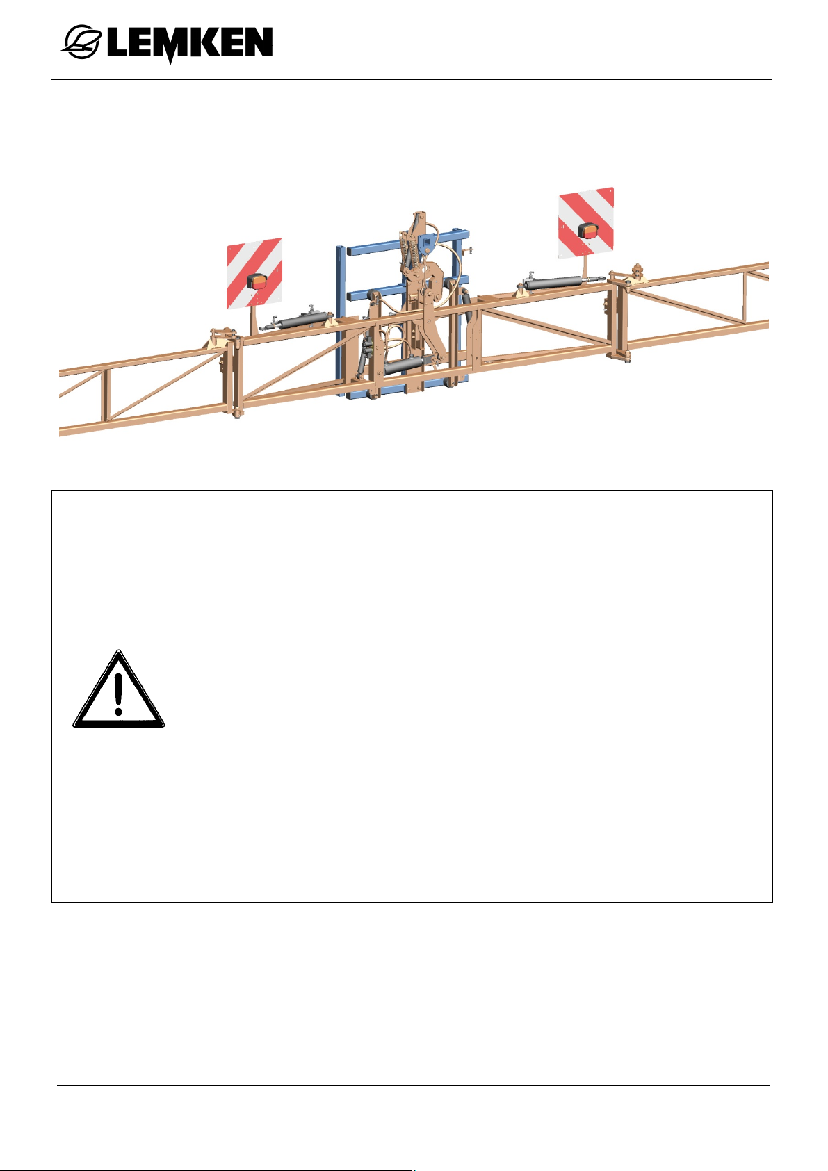
Partially folding the individual arms of the boom in or out is not
permitted. The individual arms must always be folded completely
in or out.
The boom may only be folded when stationary.
Operation of the implement with the boom completely folded out
or symmetrically folded is not permitted if the swing lock/locking is
engaged.
Symmetrical vertical folding in or out is only possible if:
the swing lock/locking is closed,
the boom is within the detection range of the height adjustment
sensor
Control with the arm 1 switch is only possible if both arms 1 are
72
fully folded backwards.
Page 73

HE Booms
13.1.1 Operation
Folding in and out of the boom is controlled via the operating terminal and the
control units of the tractor.
Depending on the equipment of the implement, the boom can be folded in or out
asymmetrically.
13.1.2 Function
A function can be pre-selected with the function keys of the operating terminal and
controlled with the tractor control unit.
13.1.3 Selecting a function
The following functions are available to deselect a function:
Press one of the other keys in the folding menu.
Select another function.
Exit from the menu.
Press the key again.
13.1.4 LED above the function key
As soon as a function has been selected with a function key, the LED for this key
illuminates. The key does not need to be held down.
13.1.5 Information in the display
If the relevant function key for the activation of a function is pressed and held
down and one or more conditions for the activation of this function are not fulfilled,
the corresponding information appears in the display.
Example
73
Page 74
13.2 Versions
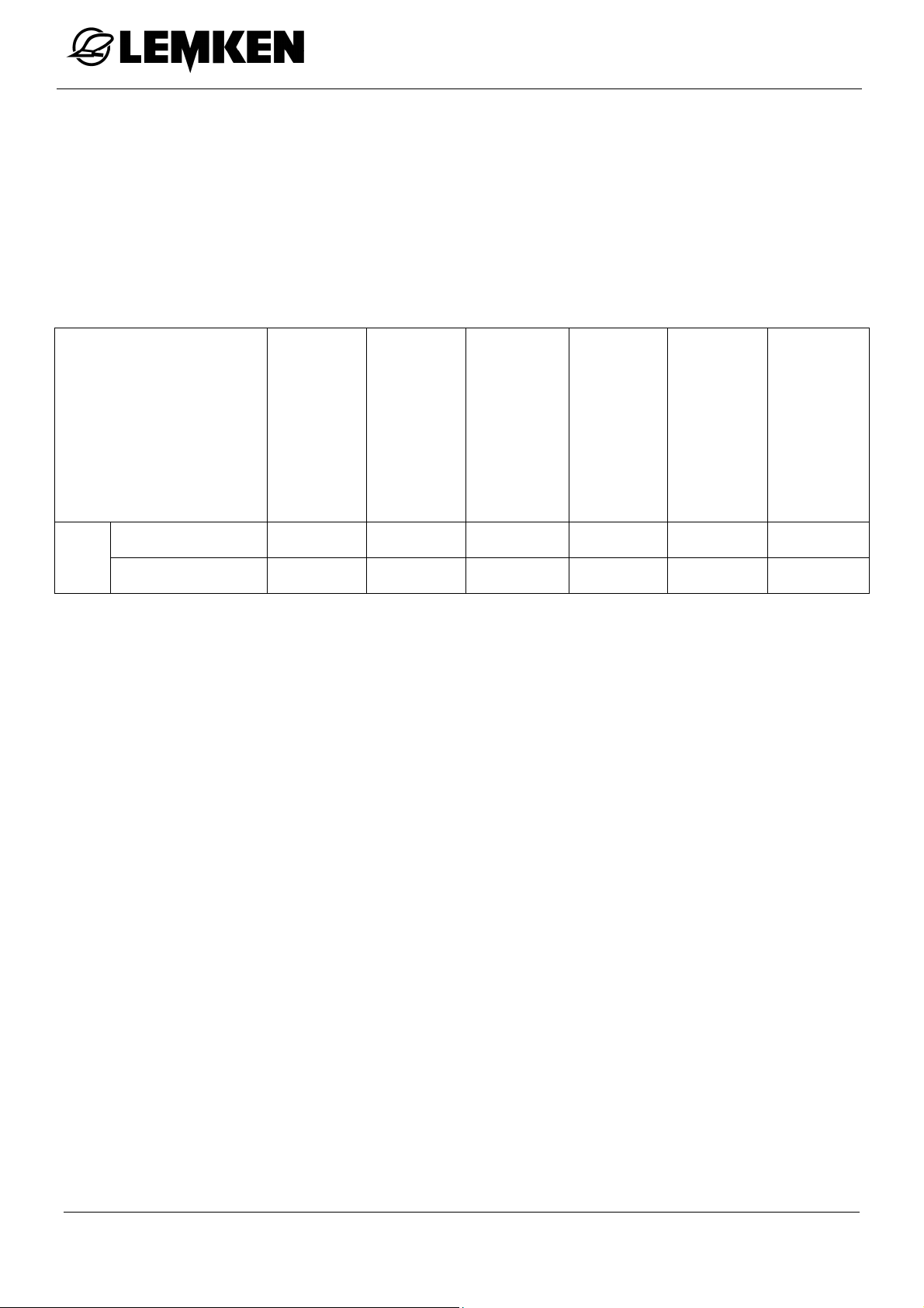
HE booms are available in two different versions:
Basic
Full
The following control units are required:
HE Booms
Basic (*) ew dw - dw -
HE
Full (*) ew dw - dw dw -
Height adjustment
Folding, asymmetri-
cal
Folding, symmetrical
(*) only in association with Closed Center hydraulic system
ew = single-acting tractor control unit
dw = double-acting tractor control unit
Swing lock
Slope compensation
Pivoting the booms
symmetrically /
asymmetrically
74
Page 75
HE Booms
13.3 Boom distribution
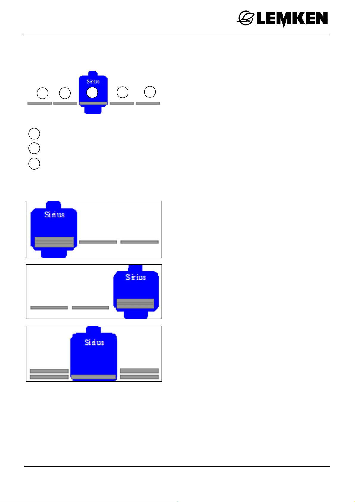
1
0
1
2
2 1
= Arm 0
= Arm 1
= Arm 2
0
Permissible folding of the arms
2
one-sided on the right
one-sided on the left
symmetrically with arm 2
75
Page 76
13.4 HE Basic boom
13.4.1 General
HE Booms
Press the key to switch on the operating
terminal.
The basic menu is displayed.
Press this key to access the first folding
menu.
The first folding menu is displayed.
Here, the following functions can be pre-
selected.
Fold left boom [F1]
Open/Close swing lock [F2/F3]
Fold right boom [F4]
76
Page 77
HE Booms
13.4.2 Swing lock
The swing lock must be closed before the
boom can be folded out:
Press one of these keys to pre-select the
or
swing lock function.
Use the relevant control unit on the trac-
tor to open or close the swing lock.
Press one of these keys to cancel the
or
pre-selection.
The following displays indicate the status of the swing lock:
The swing lock must be opened again after the boom is folded
out.
Swing lock closed
Swing lock not closed
77
Page 78
13.4.3 Foldi ng out the right boom
HE Booms
To fold out the right boom,
press this key to pre-select the right arm.
Hold this key down. Any information will
be displayed.
Use the relevant control unit on the trac-
tor to fold out the right boom.
Press this key or another function key to
cancel the pre-selection.
13.4.4 Foldi ng out the left boom
As soon as the right boom has been fully folded out, the left boom
may be fully folded out.
Press the key to select the function for
folding out the left boom.
Hold the key down. Any information will
be displayed.
Use the relevant control unit on the trac-
tor to fully fold out the left boom.
Press this key or another function key to
cancel the pre-selection.
78
Page 79
HE Booms
13.5 HE Full boom
13.5.1 General
Press the key to switch on the operating
terminal.
The basic menu is displayed.
Press this key to access the first folding
menu.
The first folding menu is displayed.
Here, the following functions can be preselected:
Fold left boom [F1]
Open/Close swing lock [F2/F3]
Fold right boom [F4]
Press this key to access the second fold-
ing menu.
The second folding menu is displayed.
Here, the following functions can be preselected:
Fold left arm 2 [F1]
Fold right arm 2 [F2]
Slope compensation[F3/F4]
79
Page 80
13.5.2 Swing lock
The swing lock must be closed before the
boom can be folded out:
Press one of these keys to pre-select the
or
swing lock function.
Use the relevant control unit on the trac-
tor to open or close the swing lock.
Press one of these keys to cancel the
or
pre-selection.
The following displays indicate the status of the swing lock:
HE Booms
Swing lock closed
Swing lock not closed
The swing lock must be opened again after the boom is folded
out.
80
Page 81
HE Booms
13.5.3 Foldi ng out the right boom
To fold out the right boom,
press this key to pre-select the right arm.
Hold this key down. Any information will
be displayed.
Use the relevant control unit on the trac-
tor to fold out the right boom.
Press this key or another function key to
cancel the pre-selection.
13.5.4 Foldi ng out the left boom
As soon as the right boom has been fully folded out, the left boom
may be fully folded out.
Press the key to select the function for
folding out the left boom.
Hold the key down. Any information will
be displayed.
Use the relevant control unit on the trac-
tor to fully fold out the left boom.
Press this key or another function key to
cancel the pre-selection.
81
Page 82
HE Booms
13.5.5 Folding arm 2
The arms can be folded in on one side in order to avoid an obstacle while working
or to only work with half of the boom width.
To pre-select the function for folding back
arm 2 on the left,
press this key in the second window of
the folding menu.
Use the relevant control unit on the trac-
tor to fold in the left arm.
Press this key or another function key to
cancel the pre-selection.
13.5.6 Slope compensator
or
Press this key to fold in arm 2 on the
right.
Press this key or another function key to
cancel the pre-selection.
To pre-select the slope compensation
function
press one of these keys in the second
window of the folding menu.
Use the relevant tractor control unit to
set the slope compensation.
Press this key or another function key to
cancel the pre-selection.
82
Page 83
Emergency switch
14 EMERGENCY SWITCH
14.1 General
This function should only be activated if:
WARNING
the boom is outside of the detection range of the arm pivoting
[SEH booms only]
there is a malfunction of the sensors on the boom.
The sensors must then be checked or another folding function
must firstly be performed, in order to carry out the required function.
The emergency switch can be used to fold the boom in and out in case of a sensor malfunction.
The emergency switch functions if a folding menu has been selected.
14.2 Ecospray operating terminal
Press and hold this key.
The display alternates between the folding
menu and the warning display.
To preselect the folding function when the
folding menu appears:
Press one of the keys.
The LED on the key illuminates.
14.3 Ecospray operating terminal with EcoControl
Press and hold this key.
At the same time, press one of the other
keys.
The corresponding function will be carried
out.
83
Page 84

14.4 Joystick box
Emergency switch
The following functions of the boom can be
controlled via the joystick box using the
emergency switch:
Pivoting arm 1, on one or both sides
Folding in and out
Press the appropriate key to activate the
required function.
Press this key.
Press the appropriate joystick to perform
the function.
Press the appropriate key to deactivate
the required function.
84
Page 85
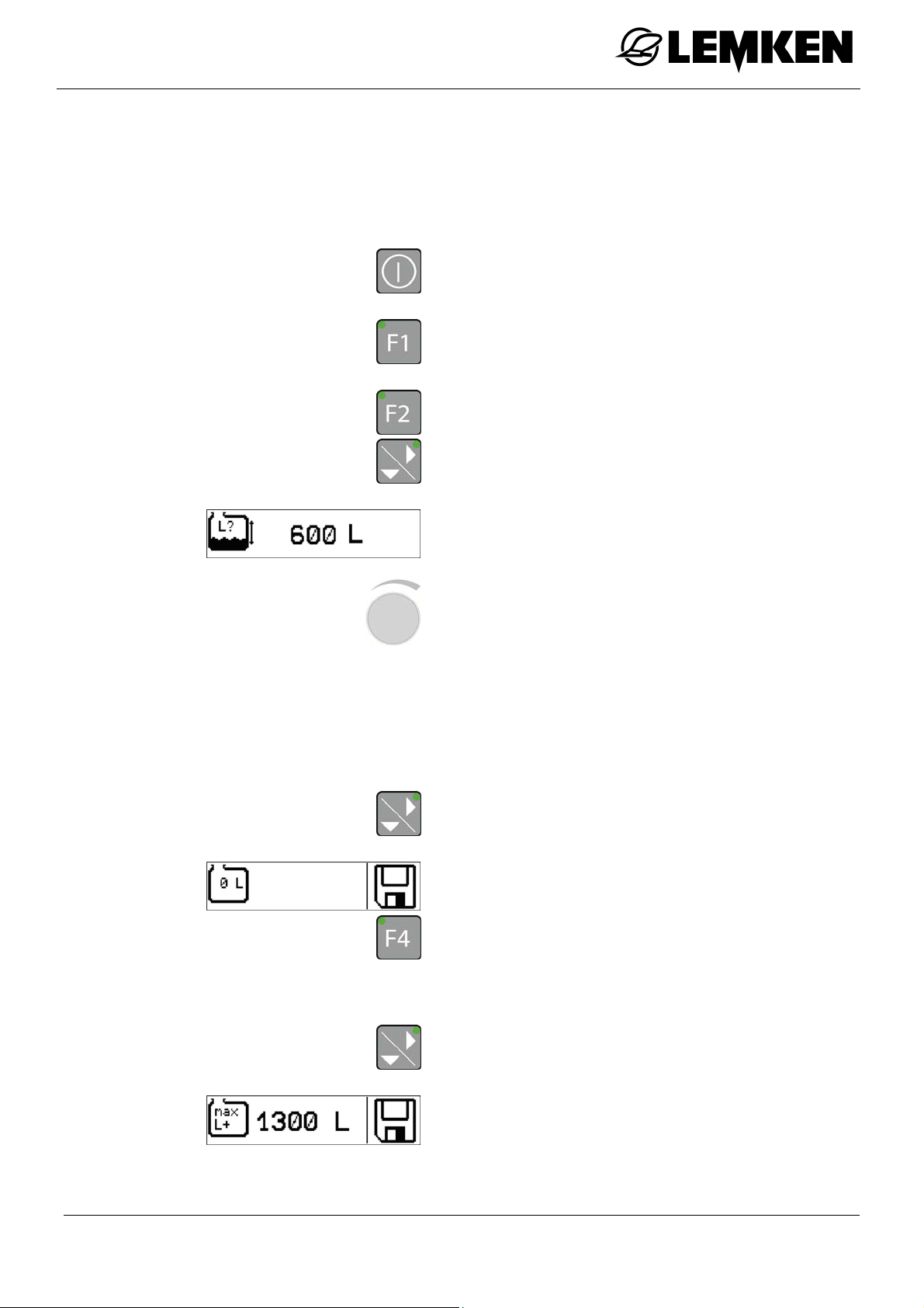
Filling the main tank
15 FILLING THE MAIN TANK
15.1 Implement without electronic fill level display
Fill the tank to the required fill level.
Press the key to switch on the operating
terminal.
Press the key to access the settings
menu.
Press the key to access the tank menu.
Press the key to display the current fill
level of the main tank.
The current filling quantity is displayed (the
filling quantity is determined theoretically).
Press the rotary encoder to select the
displayed value.
Turn the rotary encoder to enter the val-
ue.
Press the rotary encoder to confirm the
value.
Press the key to access the zero-
quantity display.
The zero-quantity display appears.
Press the key for 3 seconds to set and
save the current quantity as 0.
The word "SAVE" appears in the display.
Press the key to access the maximum
quantity display.
The maximum quantity [= nominal volume]
display appears.
85
Page 86
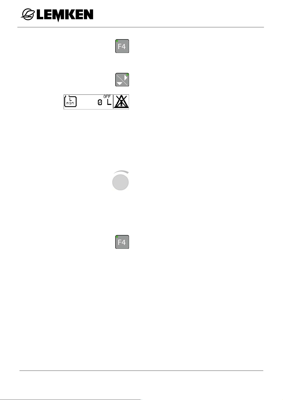
Filling the main tank
Press the key for 3 seconds to save the
maximum quantity.
The word "SAVE" appears in the display.
Press the key to access the residual
quantity alarm display.
The residual quantity alarm display appears.
OFF = Off
ON = On
The residual quantity alarm is triggered as
soon as the set residual quantity is
reached.
Press the rotary encoder to select the
displayed value.
Turn the rotary encoder to enter the val-
ue.
Press the rotary encoder to confirm the
number.
Press the key to switch the residual
quantity alarm on or off.
86
Page 87
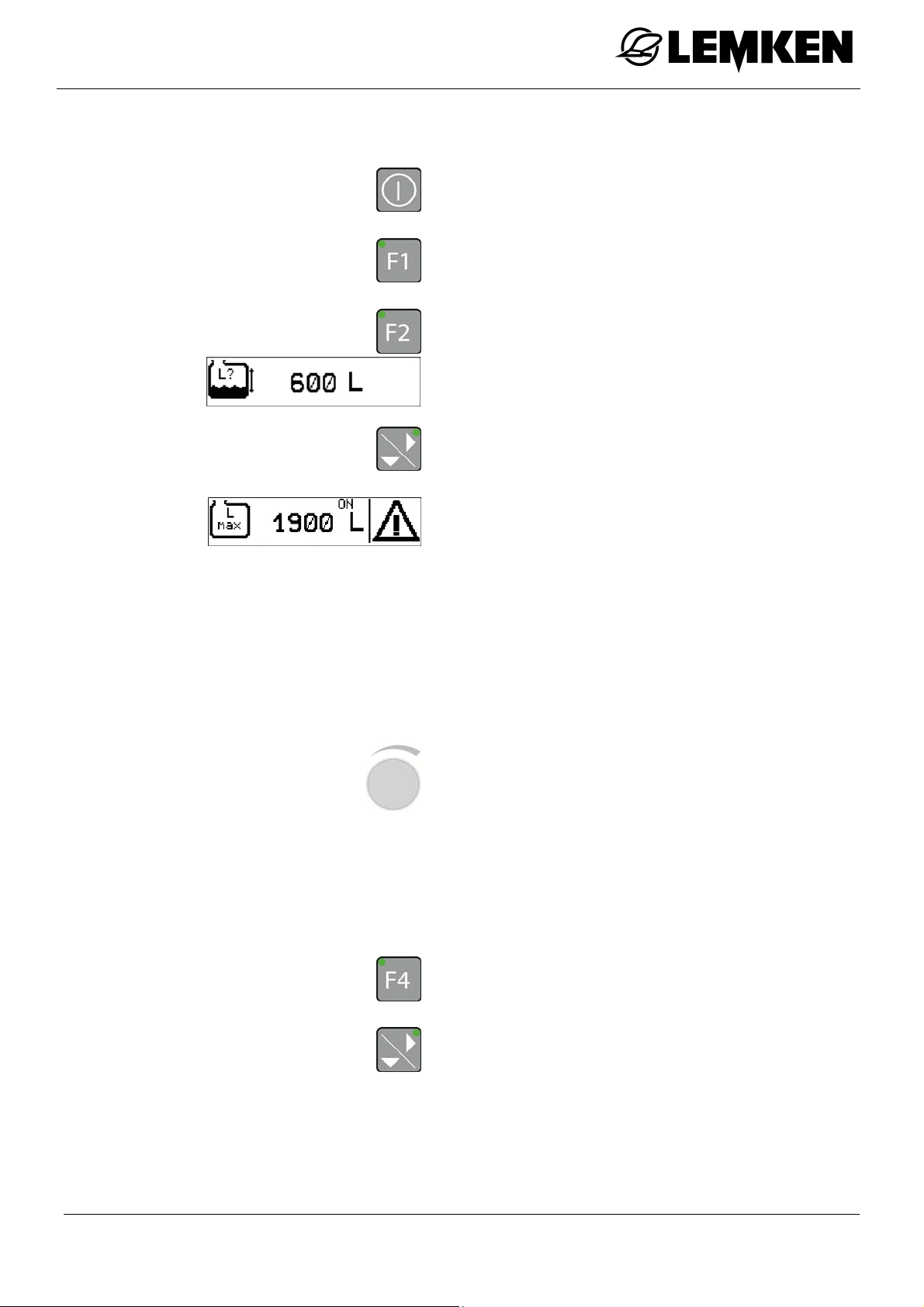
Filling the main tank
15.2 Implement with electronic fill level display
Press this key to switch on the operating
terminal.
Press this key to access the settings
menu.
Press this key to access the tank menu.
The current filling quantity is displayed (the
filling quantity is determined theoretically).
Press the key to access the maximum
quantity alarm display.
The maximum quantity alarm display appears.
ON = On
OFF = Off
The maximum quantity alarm is triggered
as soon as the set filling quantity is
reached.
Press the rotary encoder to select the
displayed value.
Turn the rotary encoder to enter the val-
ue.
Press the rotary encoder to confirm the
value.
Press the key to switch the maximum
quantity alarm on or off.
Press the key to access the residual
quantity alarm display.
87
Page 88

Filling the main tank
The residual quantity alarm display appears.
ON = On
OFF = Off
The residual quantity alarm is triggered as
soon as the set residual quantity is
reached.
Press the rotary encoder to select the
displayed value.
Turn the rotary encoder to enter the val-
ue.
Press the rotary encoder to confirm the
number.
Press the key to switch the residual
quantity alarm on or off.
88
Page 89
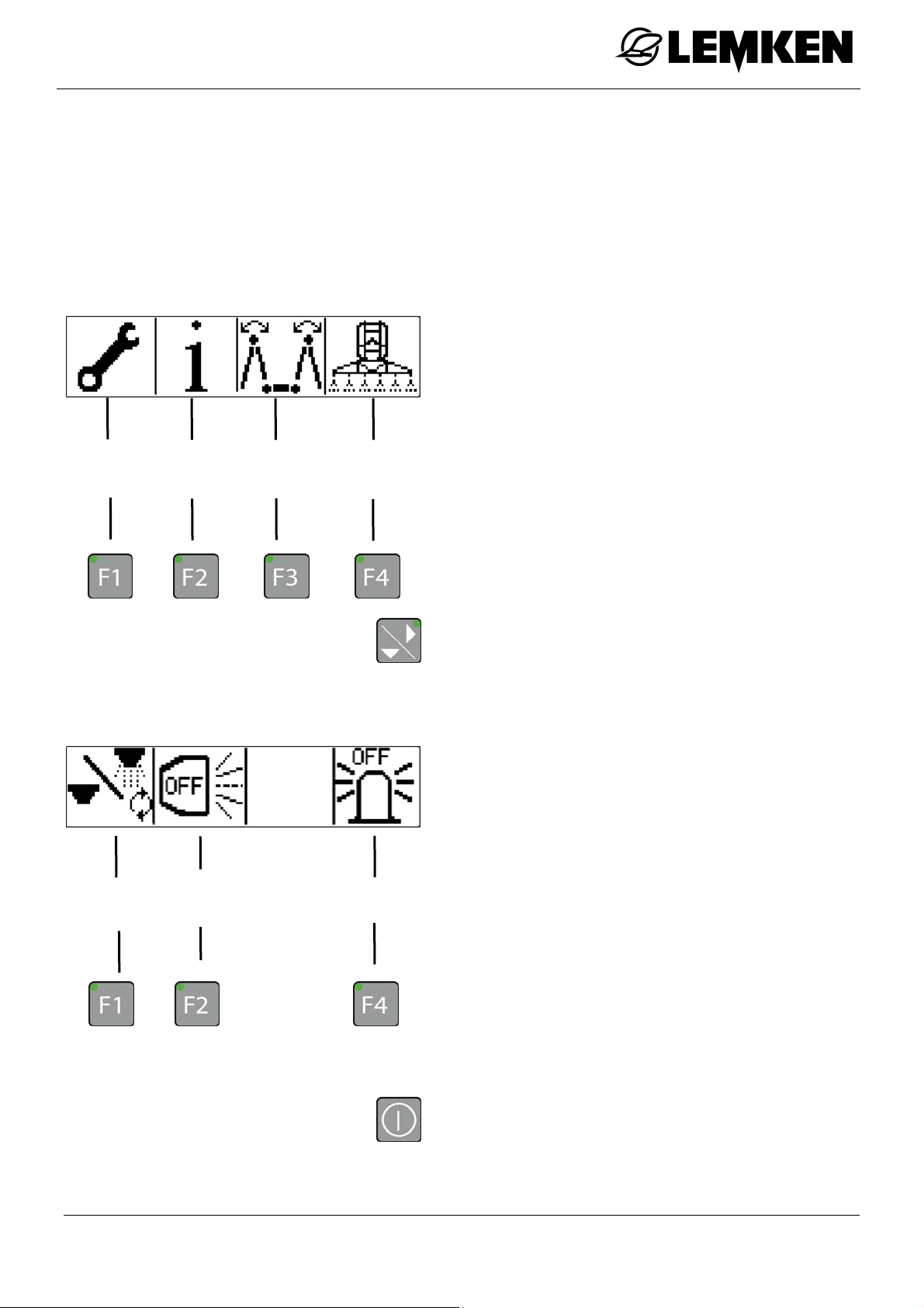
Operation
g
16 OPERATION
16.1 General
After the operating terminal is switched on, the basic menu appears. This consists
of two windows.
16.1.1 First basic menu
The first basic menu is displayed after the
operating terminal is switched on.
The first basic menu consists of further
menus:
Settings
menu
Information
menu
Folding
menu
Operating
menu
Settings menu, see »page 89«
Information menu, see »page 117«
Folding menu, see »page 126«
16.1.2 Second basic menu
Diagnos-
tic menu
Working
headlights
16.2 Settings menu
All-round
li
ht
Operating menu, see »page 128«
Press this key to access the second
basic menu.
The second basic menu appears.
This basic menu consists of further menus.
Diagnostic menu, see »page 132«
Working headlights [if fitted], see »page
133«
All-round light [if fitted], see »page 133«
Switch on the operating terminal.
89
Page 90
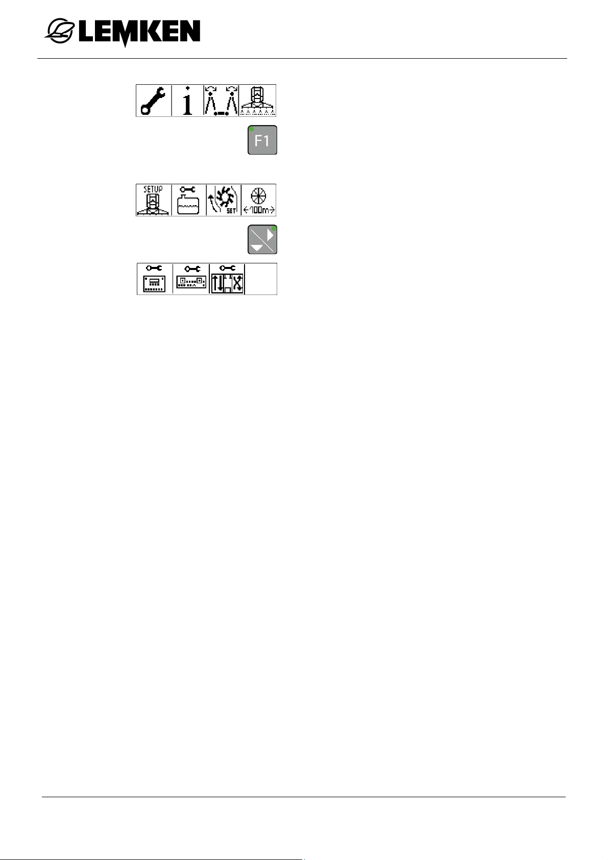
Operation
The first basic menu is displayed.
Press this key to access the settings
menu.
In the settings menu, the following further
menus can be accessed:
Implement setup [F1], see »page 91«
Tank [F2], see »page 100«
Calibration of flow meter [F3], see »page
104«
100 m calibration [F4], see »page 107«
Operating terminal settings [F1], see
»page 109«
Joystick box settings [F2], see »page
112«
Proportional valve settings [F3], see
»page 115«
90
Page 91

Operation
16.2.1 Setting up the implement
In the implement setup menu, the following
further menus can be accessed:
Distribution quantity
Increase or decrease quantity levels
Minimum control speed
Height of the boom on the headland [on-
ly for SEH Comfort and Premium booms]
Height of the boom while working [only
for SEH Comfort and Premium booms]
Move to lifting height
Simulated driving speed
Maximum spray pressure
Minimum spray pressure
Automatic swing lock
Manual reduction of outer segments
91
Page 92
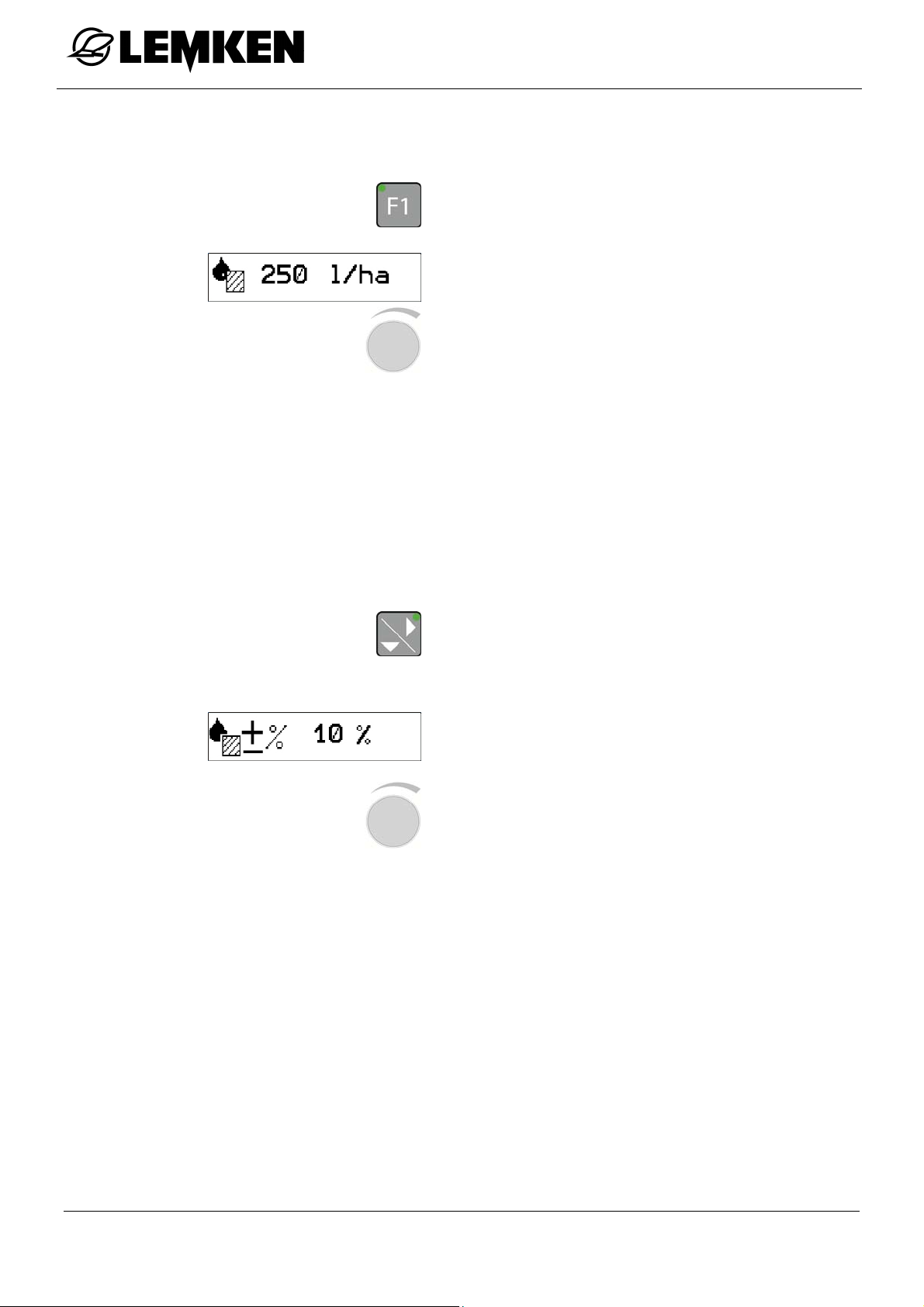
16.2.1.1 Distribution quantity
Press this key to access the implement
setup menu.
The distribution quantity in l/ha appears.
Press the rotary encoder to select the
value.
Turn the rotary encoder to enter the val-
ue.
Press the rotary encoder to save the
value.
16.2.1.2 Increased or decreased quantity levels
Operation
The increased or decreased quantity level can be adjusted in steps of 1%.
Press this key to access the display of
the increased or decreased quantity level in %.
The increased or decreased quantity level
in % appears.
Press the rotary encoder to select the
value.
Turn the rotary encoder to enter the val-
ue.
Press the rotary encoder to save the
value.
The increased or decreased quantity level can be activated in the operating menu,
see Increased or decreased quantity control, page 136.
92
Page 93
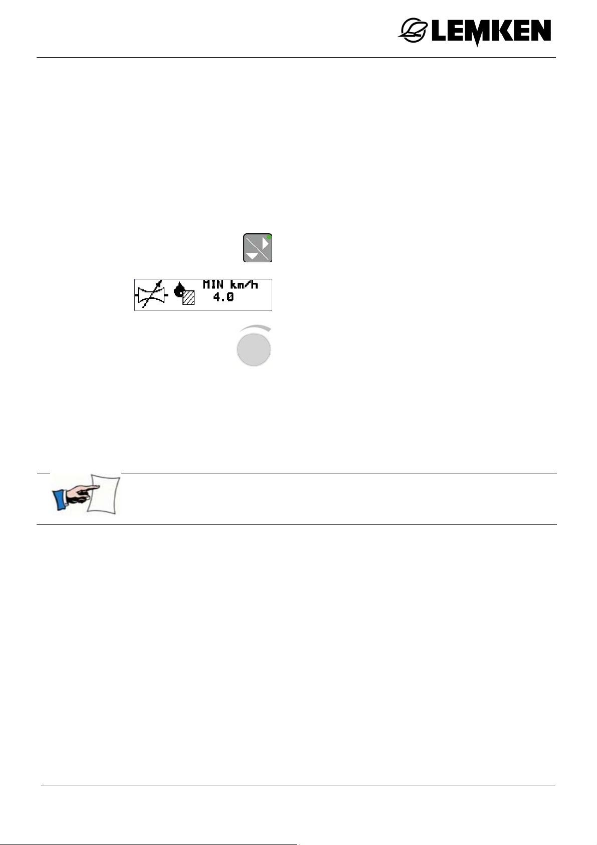
Operation
16.2.1.3 Minimum control speed
If the actual speed is below the minimum
speed setting, the minimum speed is
used for control purposes.
This can prevent too sharp a reduction in
spray pressure when moving into position.
Press this key to access the display for
minimum control speed in km/h.
The minimum control speed in km/h appears.
If the value is set to 0 km/h, the function is inactive.
Press the rotary encoder to select the
value.
Turn the rotary encoder to enter the val-
ue.
Press the rotary encoder to save the
value.
93
Page 94
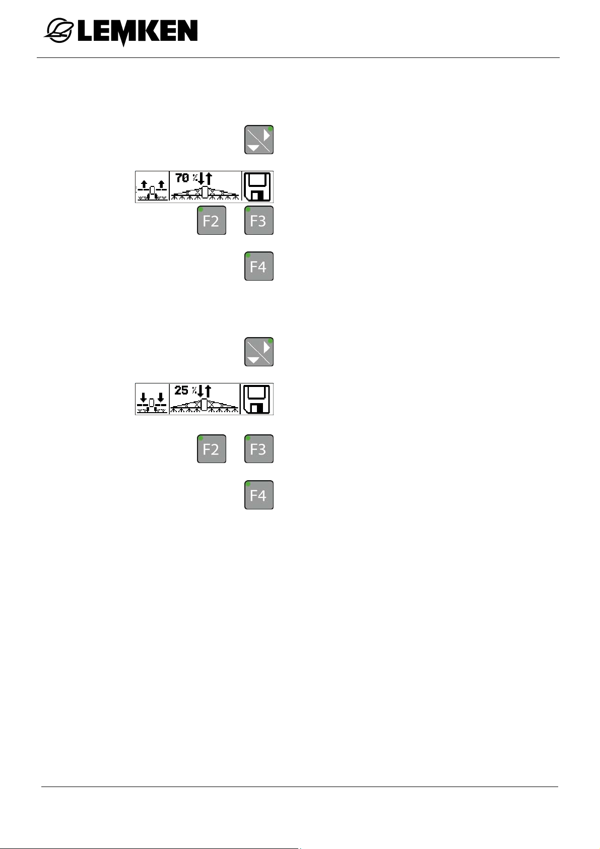
Operation
16.2.1.4 Height of the boom on the headland [for SEH Comfort and Premium
booms only]
Press this key to access the display of
the boom height on the headland.
The display appears.
Press these keys to bring the boom into
or
the required position.
Press this key to save the position.
16.2.1.5 Height of the boom while working [for SEH Comfort and SEH Premium booms only]
or
Press this key to access the display of
the working height of the boom.
The display appears.
Press these keys to bring the boom into
the required position.
Press this key to save the position.
94
Page 95
Operation
16.2.1.6 Moving to lifting mast height
If this function is active, the lifting mast
moves to the saved lifting mast height
when the main switch is pressed.
Main switch:
on = the lifting mast moves to the
off = the lifting mast moves to the
saved operating position
saved headland position
Press this key to access the display for
automatically moving to lifting mast
height.
The display for automatically moving to lifting mast height appears
ON = Function active
OFF = Function inactive
Press the rotary encoder to select the
value.
Turn the rotary encoder to enter the val-
ue.
Press the rotary encoder to save the
value.
95
Page 96
Operation
16.2.1.7 Simulated driving speed
If the speed signal fails, there is the possibility of using a simulated driving speed
in order to complete the work which has been started.
Press this key to access the display of
the simulated driving speed in km/h.
The simulated driving speed in km/h appears.
ON = On
OFF = Off
Press the rotary encoder to select the
value.
Turn the rotary encoder to enter the val-
ue.
Press the rotary encoder to save the
value.
Press this key to switch the simulated
driving speed on or off.
96
Page 97
Operation
16.2.1.8 Maximum spray pressure
According to the type of nozzle, the maximum spray pressure can be adjusted between 1 and 10 bar.
Press this key to access the maximum
spray pressure display.
The maximum spray pressure in bar appears.
Press the rotary encoder to select the
value.
Turn the rotary encoder to enter the val-
ue.
Press the rotary encoder to save the
value.
16.2.1.9 Minimum spray pressure
According to the type of nozzle, the minimum spray pressure can be adjusted between 0.5 and 10 bar.
Press this key to access the minimum
spray pressure display.
The minimum spray pressure in bar appears.
Press the rotary encoder to select the
value.
Turn the rotary encoder to enter the val-
ue.
Press the rotary encoder to save the
value.
97
Page 98
Operation
16.2.1.10 Manual reduction of outer segments
If nozzles are sealed, e.g. with plugs, the outer left and right segments must be
reduced manually according to the sealed nozzles. The outer segments on the left
and right can be reduced in 50 cm steps by up to 1.50 m.
Press this key to access the display for
manual reduction of the outer segments.
The display for the manual reduction of the
outer segments appears.
L = left outer segment
R = right outer segment
To select the left or right side:
WARNING
This setting is retained, even if the operating terminal is switched
off.
Press the rotary encoder to select the
value.
The corresponding number flashes
Turn the rotary encoder to enter the val-
ue.
Press the rotary encoder to save the
value.
If a segment has been reduced, this display appears as information when the main
switch is activated.
98
Page 99

Operation
16.2.1.11 Automatic swing lock
[SEH Booms only]
Press this key to access the automatic
swing lock display.
The automatic swing lock display appears.
ON = For symmetrical folding out of the
last arm:
the swing lock is opened automatically
for symmetrical folding in of the
last arm:
the swing lock is closed automatically.
OFF = manual opening or closing of the
swing lock
Press the rotary encoder to select the
value.
Turn the rotary encoder to enter the val-
ue.
Press the rotary encoder to save the
value.
99
Page 100
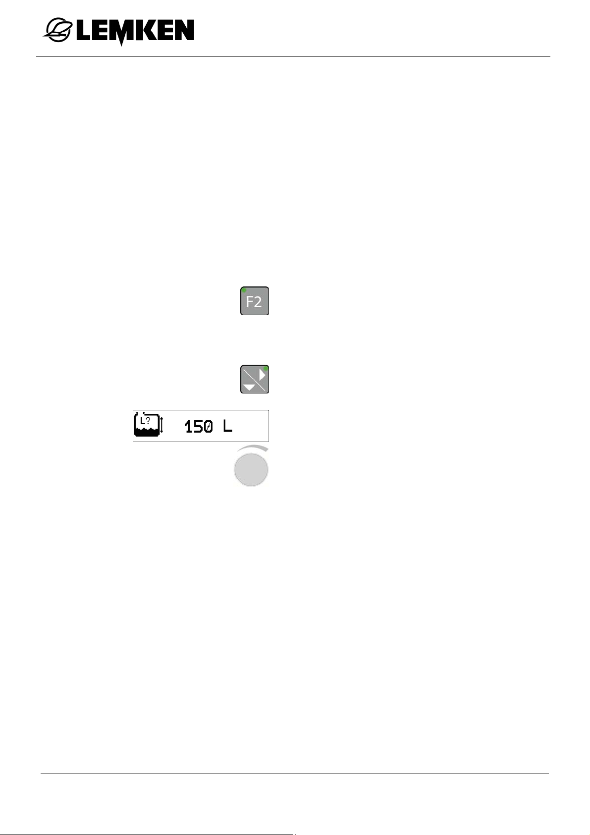
16.2.2 Tank menu
Operation
16.2.2.1 Current fill level
In the tank menu, the following further
menus can be accessed.
Current filling quantity
Zero quantity [only for implements with-
out electronic fill level display]
Maximum fill level
Residual quantity alarm
Press this key from the settings menu to
access the tank menu.
Press this key to access the current fill
level display.
The current fill level display in l appears.
Press the rotary encoder to select the
value.
Turn the rotary encoder to enter the val-
ue.
Press the rotary encoder to save the
value.
100
 Loading...