

Page 1
Page 2

The lightning flash with arrowhead symbol within an
equilateral triangle is intended to alert the user to the
presence of uninsulated "dangerous voltage" within the
product's enclosure, that may be of sufficient magnitude to
constitute a risk of electric shock to persons.
The exclamation point within an equilateral triangle is
intended to alert the user to the presence of important
operating and maintenance (servicing) instructions in the
literature accompanying the appliance.
IMPORTANT SAFETY INSTRUCTIONS
INSTRUCTIONS PERTAINING TO A RISK OF FIRE, ELECTRIC SHOCK OR INJURY TO PERSONS
WARNING - When using electric products, basic precautions should always be followed, including the
following:
1. Read all the SAFETY INSTRUCTIONS before using the product.
2. To reduce the risk of injury, close supervision is necessary when the product is used near children.
3. Do not use this product near water - for example, near a bathtub, washbowl, kitchen sink, in a wet
basement or near a swimming poor or the like.
4. This product in combination may be capable of producing sound levels that could cause
permanent hearing loss. Do not operate for a long period of time at high volume level or at a level
that is uncomfortable. If you experience any hearing loss or ringing in the ears, you should consult an
audiologist.
5. This product should be located so that its location or position does not interfere with its proper
ventilation.
6. This product should be located away from heat sources such as radiators, heat registers or other
products that produce heat.
7. The product should be connected to a power supply only of the type described on the operating
instructions or as marked on the product.
8. This product may be equipped with a polarized line plug (one blade wider than the other). This is a
safety feature. If you are unable to insert the plug into the outlet, contact an electrician to replace your
obsolete outlet. Do not defeat the safety purpose of the plug.
9. The power-supply cord of the product should be unplugged from the outlet when left unused for a
long period of time. When unplugging the power-supply cord, do not pull on the cord, but grasp it by
the plug.
10. Care should be taken so that object do not fall and liquid are not spilled into the enclosure through
openings.
11. The product should be serviced by qualifi ed service personnel when:
A. The power-supply cord or the plug has been damaged; or
B. Objects have fallen, or liquid has been spilled into the product; or
C. The product has been exposed to rain; or
D. The product does not appear to operate normally or exhibits a marked change in performance; or
E. The product has been dropped or the enclosure damaged.
12. Do not attempt to service the product beyond that described in the user-maintenance instructions.
All other servicing should be referred to qualifi ed service personnel.
13. WARNING - Do not place objects on the product's power cord or place it in a position where anyone
could trip over, walk on or roll anything over it. Do not allow the product to rest on or to be installed over
power cords of any type. Improper installations of this type create the possibility of fi re hazard and/or
personal injury.
SAVE THESE INSTRUCTIONS
Page 3

1. Introduzione
Congratulazioni per l'acquisto del sistema di diffusione
T5A!
Per un impiego corretto del sistema seguite le istruzioni
riportate in questo manuale. Buon divertimento e buon
lavoro!
2. Sommario
costituiti da due fili più una calza che funge da
schermo. L’utilizzo di cavi non schermati potrebbe
determinare l’insorgere di fastidiosi ronzii e rumori di
fondo. Verifi cate periodicamente che i cavi impiegati
siano in buono stato, con le connessioni realizzate nel
modo corretto e con tutti i contatti in perfetta effi cienza,
in modo da evitare inconvenienti come falsi contatti,
rumori di massa, scariche, ecc.
3. Norme di Installazione e Uso . . . . . . . . . 3
1. La protezione e la manutenzione . . . . . . . . . . . . 3
2. Prevenzione di possibili disturbi . . . . . . . . . . . . . 3
3. Collegamenti . . . . . . . . . . . . . . . . . . . . . . . . . . . 3
4. I cavi di collegamento. . . . . . . . . . . . . . . . . . . . . 3
4. Il sistema T5A . . . . . . . . . . . . . . . . . . . . . 3
5. Installazione e collegamenti. . . . . . . . . . 3
1. Installazione . . . . . . . . . . . . . . . . . . . . . . . . . . . . 3
2. Collegamenti . . . . . . . . . . . . . . . . . . . . . . . . . . . 3
6. Modulo DPPM - Pannello connessioni. . 4
7. PRESETS . . . . . . . . . . . . . . . . . . . . . . . . . 4
8. Il sistema di protezione. . . . . . . . . . . . . . 5
9. Funzionamento dei PLUGINS . . . . . . . . . 5
10. Specifi che tecniche. . . . . . . . . . . . . . . . 7
3. Norme di Installazione e Uso
1. La protezione e la manutenzione.
Evitate di collocare i diffusori in vicinanza di forti fonti
di calore e di esporli direttamente alla luce solare,
alla pioggia, all’umidità, alla polvere o ad intense
vibrazioni. Lasciate l’apposita griglia di protezione
sempre applicata ai diffusori. In caso di avaria non
aprite il diffusore, ma rivolgetevi al più vicino Centro di
Assistenza GENERALMUSIC.
2. Prevenzione di possibili disturbi.
Collegando gli apparati del vostro impianto audio, fate
attenzione ai cosiddetti “loop di massa” che potrebbero
causare ronzii: in caso di disturbi, provate ad agire
sullo switch SHIELD posto sul pannello controlli del
diffusore.
3. Collegamenti
Prima di collegare i diffusori alla presa di corrente,
accertatevi che la tensione di rete corrisponda a
quella indicata sul retro dell’apparato (è accettata
una tolleranza fino a ±10%). Collegate il cavo di
alimentazione al diffusore sempre prima di accenderlo e
rimuovete il cavo sempre dopo aver spento il diffusore.
Per evitare pericolosi picchi di segnale effettuate i
collegamenti con altri apparati sempre a diffusore
spento e accendete sempre prima il mixer e poi il
diffusore.
4. I cavi di collegamento
Per il collegamento dei diffusori al mixer accertatevi
di utilizzare sempre e solo cavi di segnale schermati
4. Il sistema T5A (fi g. 1)
T5A è un sistema di diffusione che integra in un
unico prodotto altoparlanti, processore digitale ed
amplifi catori di potenza. Alloggiato in un cabinet in
legno multi-strato, utilizza un driver a compressione
da 1” caricato a tromba ed un woofer da 15” con
magnete in neodimio. T5A è alimentato dal modulo di
amplifi cazione DPPM - Digitally Processed Power
Module che include un amplifi catore da 100W per il
driver, uno da 400W per il woofer ed un processore
digitale che effettua tutte le operazioni di trattamento del
segnale e di controllo del sistema (vedi fi g. 2):
- fi ltri di CROSSOVER HPF e LPF per ciascuna uscita,
confi gurabili come Butterworth, Bessel o Linkwitz/Riley
a 6, 12, 24 o 48 dB/ott.;
- fino a 25 filtri EQ configurabili come FULL
PARAMETRIC, HI e LO SHELVING a 6 o 12 dB e
NOTCH FILTER;
- DELAY LINE su ciascuna uscita per l’ALLINEAMENTO
dei singoli altoparlanti;
- correzione di FASE su ciascuna uscita con step di 5°
per un range complessivo di 360°;
- sistema integrato di protezione con LIMITER sulla
potenza di picco, protezione in potenza media contro il
surriscaldamento della bobina degli altoparlanti e LFC
(Low Frequency Control).
Sono disponibili, inoltre, 3 PLUGINS aggiuntivi,
MULTICOMP (compressore multibanda), NOISE
GATE (fi ltro di riduzione del rumore di fondo), ANTI-
FEEDBACK (sistema automatico di eliminazione dei
fenomeni di feedback) che consentono di incrementare
ulteriormente le potenzialità del sistema.
Il processore digitale include 16 PRESETS con i
parametri di funzionamento (crossover, equalizzazione,
ecc.) adatti per diversi tipi di utilizzo, che possono
essere selezionati direttamente dal pannello di
controllo.
5. Installazione e collegamenti
1. Installazione (fi g. 3)
T5A è dotato di un adattatore per l’installazione su
supporto standard per diffusori.
2. Collegamenti
L’ingresso di T5A può essere utilizzato sia con un
3
Page 4

segnale di linea che con un segnale microfonico. Per il
collegamento utilizzate cavi di segnale BILANCIATI con
connettore XLR o JACK (fi g. 4).
Il livello del segnale in ingresso può essere regolato
tramite il controllo VOL. Lasciate il controllo nella
posizione centrale (sensibilità nominale +4dB) se
collegate il diffusore all’uscita di linea di un mixer.
Se utilizzate apparecchiature con un livello di uscita
particolarmente alto, potete ruotare il potenziometro
verso sinistra riducendo il guadagno fi no alla chiusura
completa
Se collegate al diffusore un microfono dinamico oppure
un segnale di basso livello, ruotando il potenziometro
verso destra potete aumentare il livello del segnale fi no
ad un guadagno massimo di +40dB.
Per rilanciare il segnale verso un secondo diffusore
oppure verso il sub-woofer T5SA utilizzate il connettore
LINK (fi g. 5).
6. Modulo DPPM - Pannello connessioni (fi g. 6)
1. Presa per il cavo di alimentazione.
2. Interruttore di accensione/spegnimento con LED di
segnalazione
3. Connettore COMBO bilanciato per il collegamento
del segnale in ingresso.
4. Connettore XLR-M bilanciato per il rilancio del
segnale verso una seconda unità.
5. Controllo di separazione della massa elettrica
dalla massa del telaio.
6. LED bi-colore per la segnalazione della presenza
di segnale in ingresso (colore VERDE) oppure
del l’in ter ven to del LIMITER interno (colore
ROS SO).
7. Controllo del livello in ingresso.
8. Selettore a 16 posizioni per la selezione dei
PRESETS.
9. Prese d’aria per il raffreddamento del modulo di
amplifi cazione.
ATTENZIONE!!!
PER NON COMPROMETTERE IL CORRETTO
FUNZIONAMENTO DEL MODULO, E’ MOLTO
IMPORTANTE CHE LE PRESE D’ARIA SIANO
MANTENUTE SEMPRE LIBERE, PER CONSENTIRE
UNA CORRETTA CIRCOLAZIONE DELL’ARIA DI
RAFFREDDAMENTO.
7. PRESETS
I PRESETS disponibili in T5A sono stati elaborati da
LEM in collaborazione con fonici ed ingegneri del suono
allo scopo di dotare il diffusore di risposte timbriche e
dinamiche diverse a seconda del tipo di utilizzo, del
tipo di segnale riprodotto e del gusto personale. A
differenza dei diffusori amplifi cati convenzionali, grazie
alla disponibilità dei PRESETS T5A è in grado di
fornirvi esattamente il tipo suono che preferite o di cui
avete bisogno per le vostre applicazioni. Per la scelta
dei PRESETS vi consigliamo di affi darvi non solo alle
indicazioni riportate di seguito, ma soprattutto all’ascolto
e alle vostre valutazioni personali.
01. LEM INDOOR: si tratta del PRESET di base
di T5A, in grado di fornire la risposta tipica del
sistema ed utilizzabile nelle applicazioni più
comuni in ambienti chiusi.
02. LEM OUTDOOR: include una riduzione delle
frequenze alte e basse allo scopo di ottenere una
maggiore effi cacia nella risposta in gamma media.
Adatto per l’utilizzo in spazi aperti o di grandi
dimensioni.
03. FLAT (Flat Response): include solamente i fi ltri di
CROSSOVER senza equalizzazione aggiuntiva,
per ottenere una risposta in frequenza neutra.
Utilizzate questo PRESET se volete essere voi
ad equalizzare il sistema tramite i fi ltri del vostro
mixer o utilizzando un equalizzatore esterno.
04. ENTERTAIN (Entertainer): questo PRESET è
stato realizzato per l’utilizzo da parte di musicisti
di piano bar o intrattenimento in generale che
utilizzano microfoni per voce oltre a tastiere digitali
con basi MIDI o MP3, lettori MINIDISK, nonchè
altri strumenti come chitarre o fi ati. Fornisce una
risposta presente e brillante senza la necessità di
grossi interventi di equalizzazione esterni.
05. MAX LOUD (Maximum Loudness): questo
PRESET riproduce il classico effetto ‘loudness’
caratterizzato da una forte enfasi in gamma alta
e bassa, insieme ad una leggera riduzione delle
frequenze medie.
06. CD PLAYER: questo PRESET è stato elaborato
per fornire la risposta in frequenza ideale per la
riproduzione di musica registrata ed è, pertanto,
adatto per DJ ed installazioni in locali pubblici
come pubs, disco bar e ristoranti. Il PRESET
include l’utilizzo del compressore multibanda
per ottenere la massima risposta dinamica in
condizioni di sicurezza.
07. WALL MOUNT: questo PRESET include una
correzione in gamma bassa per ottimizzare la
risposta in caso di installazione del diffusore in
stretta prossimità di una parete.
08. STAGE MONITOR: si tratta di un PRESET
realizzato prevedendo l’utilizzo di T5A come
monitor da palco, in posizione verticale e collocato
a fi anco del musicista. La risposta del diffusore in
gamma medio-alta è stata modifi cata per fornire
un ascolto migliore a distanza ravvicinata e,
4
Page 5

insieme all’utilizzo del plugin ANTI-FEEDBACK,
per ridurre al minimo i fenomeni di feedback (vedi
paragrafo sull’utilizzo dell’ANTI-FEEDBACK)
09. LEM INDOOR SW: si tratta del PRESET INDOOR
con un fi ltro PASSA ALTO a 100Hz per l’utilizzo del
diffusore con il sub-woofer LEM T5SA.
10. LEM OUTDOOR SW: si tratta del PRESET
OUTDOOR con un fi ltro PASSA ALTO a 100Hz per
l’utilizzo del diffusore con il sub-woofer LEM T5SA.
11. FLAT SW: si tratta del PRESET FLAT con un fi ltro
PASSA ALTO a 100Hz per l’utilizzo del diffusore
con il sub-woofer LEM T5SA.
12. ENTERTAIN SW: si tratta del PRESET
ENTERTAIN con un fi ltro PASSA ALTO a 100Hz
per l’utilizzo del diffusore con il sub-woofer LEM
T5SA.
13. MAX LOUD SW: si tratta del PRESET MAX LOUD
con un fi ltro PASSA ALTO a 100Hz per l’utilizzo del
diffusore con il sub-woofer LEM T5SA.
14. CD PLAYER SW: si tratta del PRESET CD
PLAYER con un fi ltro PASSA ALTO a 100Hz per
l’utilizzo del diffusore con il sub-woofer LEM T5SA.
15. WALL MOUNT SW: si tratta del PRESET CD
PLAYER con un fi ltro PASSA ALTO a 100Hz per
l’utilizzo del diffusore con il sub-woofer LEM T5SA.
16. MIC PLUG&PLAY: questo PRESET può essere
utilizzato quando al diffusore viene collegato
direttamente un microfono dinamico. Il PRESET
contiene una equalizzazione che consente di
ottenere dal microfono una risposta chiara ed
intelligibile senza bisogno del mixer. In più, il
plugin ANTI-FEEDBACK consente di ridurre al
minimo i fenomeni di feedback (vedi paragrafo
sull’utilizzo dell’ANTI-FEEDBACK).
8. Il sistema di protezione
Il modulo DPPM di T5A è dotato di una serie di
dispositivi digitali che consentono di ottenere un livello
elevatissimo di protezione degli altoparlanti e degli
amplifi catori del sistema (vedi fi g. 2).
- LIMITERS sulla potenza di PICCO: sono in grado
di prevenire con estrema precisione il clipping degli
amplifi catori interni e, allo stesso tempo, di controllare
la potenza massima di picco erogata agli altoparlanti.
L’intervento di questa protezione è segnalato dal LED
SIGNAL/LIMIT posto sul pannello.
Nota: sebbene i LIMITERS digitali agiscano con grande
precisione ed effi cacia, si consiglia di non eccedere con
il livello di ingresso e di operare in una condizione in cui
il LED rosso LIMIT lampeggi solo occasionalmente.
- PROTEZIONE IN POTENZA CONTINUA: interviene
quando il sistema viene utilizzato in modo prolungato
al limite della potenza media sopportabile dagli
altoparlanti. Il processore digitale è in grado di rilevare
se uno degli altoparlanti del sistema stia raggiungendo
la temperatura massima sopportabile dalla bobina
mobile. In questo caso, il segnale (e, quindi, la
potenza applicata) viene ridotto in modo graduale fi no
a portare l’altoparlante entro i limiti di sicurezza. Se la
situazione di rischio permane, la potenza resta ridotta,
mentre se si ripristina la condizione di utilizzo corretto
essa viene riportata gradualmente al livello normale.
Tale protezione, che agisce in modo completamente
automatico ed inavvertibile, impedisce che un utilizzo
esasperato del sistema possa provocare la rottura degli
altoparlanti.
- LFC (Low Frequency Control): si tratta di un
compressore selettivo che consente di operare una
ulteriore protezione su una limitata banda di frequenze
alle quali il woofer è più suscettibile di possibili rotture.
9. Funzionamento dei PLUGINS
- MULTICOMP: si tratta di un compressore multibanda formato da due compressori separati in grado
di operare su due bande di frequenza selezionabili
(HIGH e LOW). Il MULTICOMP viene utilizzato in alcuni
PRESETS di T5A per l’equalizzazione dinamica del
sistema, per ottenere effetti di loudness e per applicare
una protezione aggiuntiva solo su bande di frequenza
defi nite.
- NOISE GATE: si tratta di un filtro dinamico in
grado di eliminare il rumore di fondo proveniente
dalle apparecchiature collegate ai diffusori. Il fi ltro di
NOISE GATE è attivo in tutti i PRESETS di T5A (con
l’eccezione del PRESET STAGE MONITOR e del
PRESET MIC PLUG&PLAY).
- ANTI-FEEDBACK: è un sistema è in grado di rilevare
automaticamente frequenze di feedback e di eliminarle
tramite 10 fi ltri notch. 7 dei 10 fi ltri disponibili operano in
modalità SINGLE, vale a dire che una volta posizionati
su una frequenza rimangono in posizione. I rimanenti 3
fi ltri sono settati in modalità AUTO e, pertanto, anche se
posizionati su una certa frequenza, nel caso si verifi chi
un feedback su una frequenza diversa sono in grado
di spostarsi automaticamente su di essa. Tutti i fi ltri
vengono azzerati (RESET) ogni volta che il diffusore
viene spento e, una volta che il diffusore viene riacceso,
riposizionati nuovamente nel caso si manifestino
fenomeni di feedback.
Il PLUGIN ANTI-FEEDBACK è attivo nei PRESETS
STAGE MONITOR e MIC PLUG&PLAY. Per poterlo
sfruttare nel modo migliore vi consigliamo di effettuare
alcune semplici operazioni preparatorie PRIMA
dell’utilizzo dei diffusori:
5
Page 6

a. collocate i diffusori ed i microfoni nelle posizioni in cui
verranno utilizzati;
b. alzate lentamente il volume del o dei microfoni fi no al
verifi carsi dei fenomeni di feedback: il sistema attiverà
i fi ltri notch in successione in corrispondenza delle
frequenze interessate;
c. se necessario, effettuate dei movimenti con il
microfono all’interno dell’area di utilizzo;
d. riportate il volume al livello normale.
A questo punto i filtri notch saranno posizionati in
corrispondenza delle frequenze più facilmente soggette
ai feedback e, pertanto, nel caso il volume dei microfoni
venga aumentato durante l’utilizzo, saranno in grado di
ridurre tali fenomeni.
ATTENZIONE!!!
L’ANTI-FEEDBACK implementato in T5A non è
in grado di eliminare completamente
di feedback, ma solo di ridurre il rischio che si
verifi chino, in modo tale da consentire l’utilizzo del
sistema a volumi più elevati del normale ed anche in
condizioni critiche (microfoni posizionati di fronte ai
diffusori, microfoni in movimento, ecc.).
i fenomeni
6
Page 7
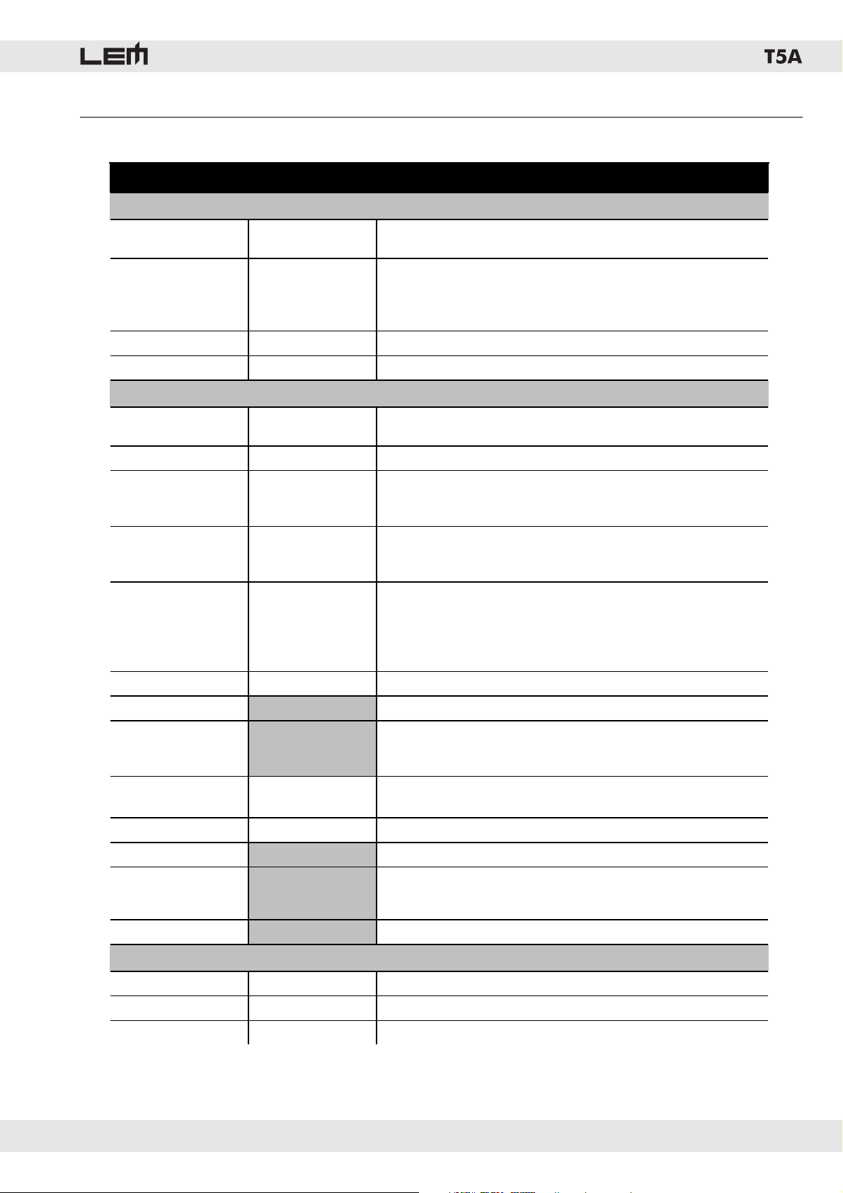
10. Specifi che tecniche
Componenti
Costruzione
Dimensioni
Peso
Ingresso
Convertitori A/D
Convertitori D/A
Crossover
EQ
Alignment delay
Plugins
Protezioni
Potenza di uscita
EIA (1kHz, THD 1%)
Distorsione
Controlli
Connessioni
T5A • SPECIFICHE TECNICHE
SPECIFICHE del DIFFUSORE
Alti
Bassi
Cabinet
Protezione
Trasporto e
installazione
mm (LxAxP) 456x690x430
kg 32
SPECIFICHE dell’AMPLIFICATORE
sensibilità
impedenza
bit 24
bit
Range dinamico
Sampling Rate
Tipo
Frequenza
Pendenza
Numero
Tipo
Peak, 6dB Lo-Shelf, 12dB Lo-Shelf, 6dB Hi-Shelf, 12dB Lo-Shelf, Notch
Guadagno
Banda
Frequenza
max delay 189 ms
W Alti
W Bassi
% <0.02
1 x COMBO (ingresso LINE + MIC) - 1 x XLR-M (link) - Connettore di
Da 0.05 a 3.00 ottave, variabile in step da 0.05
Noise Gate, Anti-feedback, Multiband compressor
Limiter di picco indipendente su ciascuna uscita
Protezione in potenza continua su ciascuna uscita
Driver da 1” con CD horn
Woofer da 15”
Multistrato con vernice nera antigraffi o
Griglia metallica di protezione
Maniglie ed adattatore in metallo
+4 dB (nominale) / -40dB (massima)
20 kOhms (bilanciato)
100 dB
48 kHz
Bessel, Butterworth o Linkwitz-Riley
Variabile da 15.6 Hz a 16 kHz
6, 12, 18 o 24 dB per ottava
25 bande parametriche
+/-15dB, variabile in step da 0.5dB
Da 15.6 Hz a 16 kHz
LFC - Low Frequency Control
Volume - Selettore PRESETS
alimentazione
24
100
400
Alimentazione
Risposta in frequenza
Sensibilità
Dispersione
vedi etichetta sull’apparato
SPECIFICHE del SISTEMA
Hz (-10dB) 60 - 20000
MAX SPL Continuous 122
° 80 x 80
7
Page 8

1. Introduction
Congratulations for having chosen the T5A loudspeaker
system!
To make the best use of the system, please read this
manual thoroughly before operating the equipment.
2. Contents
3. Instructions for use and installation . . . 8
1. Protection and maintenance. . . . . . . . . . . . . . . . 8
2. Prevention of possible interference . . . . . . . . . . 8
3. Connections . . . . . . . . . . . . . . . . . . . . . . . . . . . . 8
4. Connector cables . . . . . . . . . . . . . . . . . . . . . . . . 8
4. The T5A system. . . . . . . . . . . . . . . . . . . . 8
5. Installation and connections . . . . . . . . . 8
1. Installation . . . . . . . . . . . . . . . . . . . . . . . . . . . . . 8
2. Connections . . . . . . . . . . . . . . . . . . . . . . . . . . . . 8
6. DPPM module - Connection panel . . . . . 9
7. PRESETS . . . . . . . . . . . . . . . . . . . . . . . . . 9
8. The protection system . . . . . . . . . . . . . 10
9. How the PLUGINS work . . . . . . . . . . . . 10
10. Technical specifi cations . . . . . . . . . . . 12
3. Instructions for use and installation
1. Protection and maintenance.
To avoid jeopardizing correct operation, it is best not
to position the enclosures for long periods in exposed
places (damp, high temperature, etc.), in dusty
environments or those subject to strong vibrations. On
this subject, it’s advisable to always leave the protective
grille mounted on the enclosures. In the event of
breakdown, do not open the enclosure, but contact the
nearest GENERALMUSIC Service Centre.
2. Prevention of possible interference.
Avoid installing your equipment in the vicinity of
radios, televisions, etc., since this could cause noisy
disturbance. When connecting other equipment to
your sound system, pay close attention to so-called
earth-loops, which can cause hum: in the event of
interference, try using the SHIELD switch on the unit’s
control panel.
3. Connections.
Before connecting the enclosures to the mains
supply, make certain that the current corresponds
with that indicated on the rear of the units (there is an
allowance of ±10%). Always connect the power cable
to the enclosures before switching them on and always
remove it after having switched off. Remember to
always connect or disconnect other equipment with the
enclosures off and to always switch on the mixer fi rst,
then the enclosures: in this manner, annoying and often
dangerous peaks are avoided.
4. Connector cables.
When connecting the enclosures to the mixer, make
certain to always use only screened signal cables
made up of two wires plus a braid/screen: the use
of unscreened cables could in fact probably cause
annoying hum and noise. Check periodically that your
cables are in good condition, correctly wired and with
perfectly effi cient contacts: in fact many problems and
drawbacks (false contacts, ground hum, crackles,
etc.) are caused by the use of unsuitable or damaged
cables.
4. The T5A system (fi g. 1)
T5A is a system that integrates in the same unit
loudspeakers, amplifiers and digital processor.
The system, hosted in plywood cabinet, utilizes a
1” horn-loaded compression driver and a 15” woofer
with neodymium magnet. It’s powered by the DPPM
- Digitally Processed Power Module, which includes
a 100W power amplifi er for the driver, a 400W power
amplifi er for the woofer and a digital processor able to
handle all the signal processing needed for the system
control (see fi g. 2):
- HPF and LPF CROSSOVER fi lters with the choice
between Butterworth, Bessel or Linkwitz/Riley response
and up to 48 dB/oct. slope;
- up to 25 EQ fi lters that can be individually set as
FULL PARAMETRIC, HI and LO SHELVING (6 or 12 dB
slope) or NOTCH FILTER;
- DELAY LINES on each for the LOUDSPEAKER
alignment;
- PHASE adjustment with 5° step through a full 360°;
- integrated protection system with high precision PEAK
LIMITERS, long term power protection and LFC (Low
Frequency Control)
3 additional PLUGINS are also available, which allows
the system performances to be further increased:
MULTICOMP (Multiband Compressor), NOISE GATE
and ANTI-FEEDBACK.
The digital processor includes 16 PRESETS, which can
be recalled directly from the system’s panel and which
include different settings suitable for the use of the
system in different confi gurations.
5. Installation and connections
1. Installation (fi g. 3)
T5A is fi tted with an adapter for the installation on a
standard loudspeaker stand.
2. Connections
The input of the T5A can be used to connect both line and
microphone signals. For the connection make use of XLR
or 1/4” JACK BALANCED signal cables (fi g. 4).
8
Page 9

The input level of the incoming signal can be set using
the VOL control. Leave the control in the CENTER
position (nominal input sensitivity +4dB) if the T5A is
connected to the line output of a mixer.
If you are using devices with a too high output level,
you can reduce the input gain turning the control
counterclockwise.
If you connect to the T5A a dynamic microphone or a
low-level signal you gain increase the input gain up to
+40dB turning the control clockwise.
If you need to send the same signal to a second T5A or
to the T5SA sub-woofer you can use the XLR-M LINK
connector (fi g. 5).
6. DPPM module - Connection panel (fi g. 6)
1. Power supply cable socket.
2. ON/OFF switch with LED indicator.
3. Balanced COMBO socket for the input signal
connection.
4. Balanced XLR-M socket for the signal linking to a
second unit.
5. Control for separating the electrical earth from that
of the chassis.
6. Two-color LED that illuminates when there’s a
signal present at the unit’s input (GREEN color) or
when the internal LIMITER is active (RED color).
7. Input level control.
8. 16-position encoder for the PRESET’s selection.
9...Air vents for the module cooling.
WARNING!!!
IN ORDER FOR THE MODULE TO WORK
CORRECTLY, IT’S VERY IMPORTANT TO KEEP THE
AIR VENTS ALWAYS FREE AND ABLE TO PROVIDE
A PROPER AIR CIRCULATION.
7. PRESETS
The PRESETS available in the T5A have been prepared
by LEM with the support of sound engineers and audio
technicians in order to provide the loudspeaker system
with different acoustical and dynamic responses suitable
for different applications, different kind of signal and
different tastes. Unlike the conventional loudspeaker
systems, T5A is able to give you exactly the kind of
sound you prefer or you need for your applications. For
the PRESET’s choice we suggest not only to follow the
directions you can fi nd below, but also to rely on the
listening and on your personal evaluations.
01. LEM INDOOR: this is the T5A DEFAULT PRESET,
giving the typical response of the system and
suitable for the most common indoor applications.
02. LEM OUTDOOR: a slight cut in the high and low
frequency region results in an improved effi ciency
in the mid region. Suitable for the most common
applications in outdoor spaces and large venues.
03. FLAT (Flat Response): includes only the
CROSSOVER fi lters without any additional EQ,
in order to obtain the ‘natural’ response of the
system’s loudspeakers. Choose this PRESET if
you want to EQ the system by yourself using the
mixer’s EQ fi lters or an external equalizer.
04. ENTERTAIN (Entertainer): this PRESET
has been prepared for piano bar players and
entertaining musicians who use vocal microphones
together with digital keyboard with MIDI or MP3
songs, MINIDISK players or other instruments
like guitars and horns. It gives a crisp sound and
a clear response without the need of massive
external equalizations.
05. MAX LOUD (Maximum Loudness) : this PRESET
reproduces the classic ‘loudness’ effect with a big
boost in the high and low end and a slight cut in
the mid region.
06. CD PLAYER: this PRESET has been prepared
to provide the best frequency response for the
reproduction of recorded music and is suitable for
DJs and as a P.A. system for installations in pubs,
disco bars and restaurants. It includes the use of
the multiband compressor for the best dynamic
response together with the maximum protection.
07. WALL MOUNT: this PRESET includes an
adjustment in the low range to optimize the
response when the speaker is installed lose to a
wall. .
08. STAGE MONITOR: this is the PRESET to be
chosen when the T5A is used as a stage monitor,
in vertical position and, usually, at the musician’s
side. The mid-high frequency response has been
adjusted in order to obtain a better near-fi eld
listening and, together with the use of the ANTIFEEDBACK plugin, to reduce to the minimum the
feedback phenomena (see the ANTI-FEEDBACK
section).
09. LEM INDOOR SW: this is the LEM INDOOR
PRESET with a 100Hz high-pass fi lter for the use
of the T5A with the LEM sub-woofer T5SA.
10. LEM OUTDOOR SW: this is the LEM OUTDOOR
PRESET with a 100Hz high-pass fi lter for the use
of the T5A with the LEM sub-woofer T5SA.
11. FLAT SW: this is the FLAT PRESET with a 100Hz
high-pass fi lter for the use of the T5A with the LEM
sub-woofer T5SA.
12. ENTERTAIN SW: this is the ENTERTAIN PRESET
with a 100Hz high-pass fi lter for the use of the T5A
with the LEM sub-woofer T5SA.
13. MAX LOUD SW: this is the MAX LOUD PRESET
with a 100Hz high-pass fi lter for the use of the T5A
9
Page 10

with the LEM sub-woofer T5SA.
14. CD PLAYER SW: this is the CD PLAYER PRESET
with a 100Hz high-pass fi lter for the use of the T5A
with the LEM sub-woofer T5SA.
15. WALL MOUNT SW: this is the WALL MOUNT
PRESET with a 100Hz high-pass fi lter for the use
of the T5A with the LEM sub-woofer T5SA.
16. MIC PLUG&PLAY: this PRESET can be used
when you connect a dynamic microphone directly
to the T5A input. The equalization contained in
this PRESET allows to get from the microphone
a brilliant and intelligible response even
without using a mixer. In addition the use of the
ANTI-FEEDBACK plugin allows the feedback
phenomena to be reduced to the minimum (see
the ANTI-FEEDBACK section).
8. The protection system
The DPPM module includes a series of digital algorithms
that allows very high level of protection of the speakers
and the amplifi ers to be achieved (see fi g. 2).
- PEAK LIMITERS: they are able to avoid with
extreme precision the amplifi er’s clipping and, at the
same time, to control the maximum peak power sent
to the loudspeakers. The SIGNAL/LIMIT LED on the
module’s panel lights (RED color) when the LIMITERS
are active.
Note: even if the digital LIMITERS can work with
extreme precision and effi ciency, it’s always advisable
to avoid too high signal levels and to prevent the LIMIT
LED to blink
- LONG TERM POWER PROTECTION: this protection
acts when the T5A is used continuously at the
maximum power allowed for each loudspeaker. The
digital processor is able to detect if one of the system’s
loudspeaker is reaching the maximum temperature
allowable for its voice coil. In this case, the output signal
(and, consequently, the power applied to that speaker)
is slowly reduced in order to take back the system within
safety limits. The power reduction is maintained until the
critical condition remains. As soon as a normal working
condition is restored, the power is gradually taken back
to the nominal level. This protection, which is completely
automatic and doesn’t affect the dynamic performance
of the system, is able to prevent damages to the
speakers when the T5A is used in extreme conditions.
- LFC (Low Frequency Control): this is a frequency-
dependent compressor able to perform an additional
protection over a limited frequency band where the
woofer is more liable to be damaged by excessive
power.
9. How the PLUGINS work
- MULTICOMP: it’s a multiband compressor made of
two separate compression units able to operate on two
user-selectable frequency bands (HIGH and LOW). The
MULTICOMP is used in some of the T4A’s PRESETS
for the system’s dynamic EQ, to obtain loudness effects
or to apply an additional protection on defi ned frequency
bands.
- NOISE GATE: it’s a dynamic fi lter able to eliminate the
background noise coming from the devices connected
to the enclosure input. The NOISE GATE fi lter is active
on all the T4A’s PRESETS (with the exception of the
STAGE MONITOR and MIC PLUG&PLAY PRESETS).
- ANTI-FEEDBACK: it’s a system able to identify
feedbacks and automatically reduce them by means
of 10 notch fi lters. 7 of the 10 available notch fi lters
operates in SINGLE mode, meaning that once they
have been placed on a certain frequency they remain
on that frequency until the RESET button is pressed.
The remaining 3 fi lters operate in AUTO mode and,
therefore, once they have been placed on a certain
feedback frequency, every time a new one is identifi ed
by the system, they move from the original one to the
new one. All the fi lters are reset every time the T5A is
switched off and, when it is switched on, they can be
activated again if some feedback frequency comes
out.
The ANTI-FEEDBACK PLUGIN is active in the STAGE
MONITOR and MIC PLUG&PLAY PRESETS. To make
the most of it we suggest to follow this procedure:
a. place the speakers and the microphones in their
usual positions;
b. raise slowly the microphone’s volume until the
feedbacks are produced by the speakers: the
system will place the notch filters on the feedback
frequencies;
c. if needed, move the microphone all around the area
where they will be used;
d. take back the microphone’s volume at its normal
level.
Now the notch filters have been placed on the
frequencies where the feedbacks are more likely to
appear and, therefore, in case the microphone level
is raised during the performance, they will be able to
reduce them.
ATTENTION!!!
The T5A’s ANTI-FEEDBACK in not able to eliminate
completely the feedbacks, but it can reduce the risk
that they happens during a performance. This allows
the use of the system at a higher level than usual
and also in critical conditions as, for example, with
the microphones placed in front of the speakers or
10
Page 11

with moving microphones.
11
Page 12
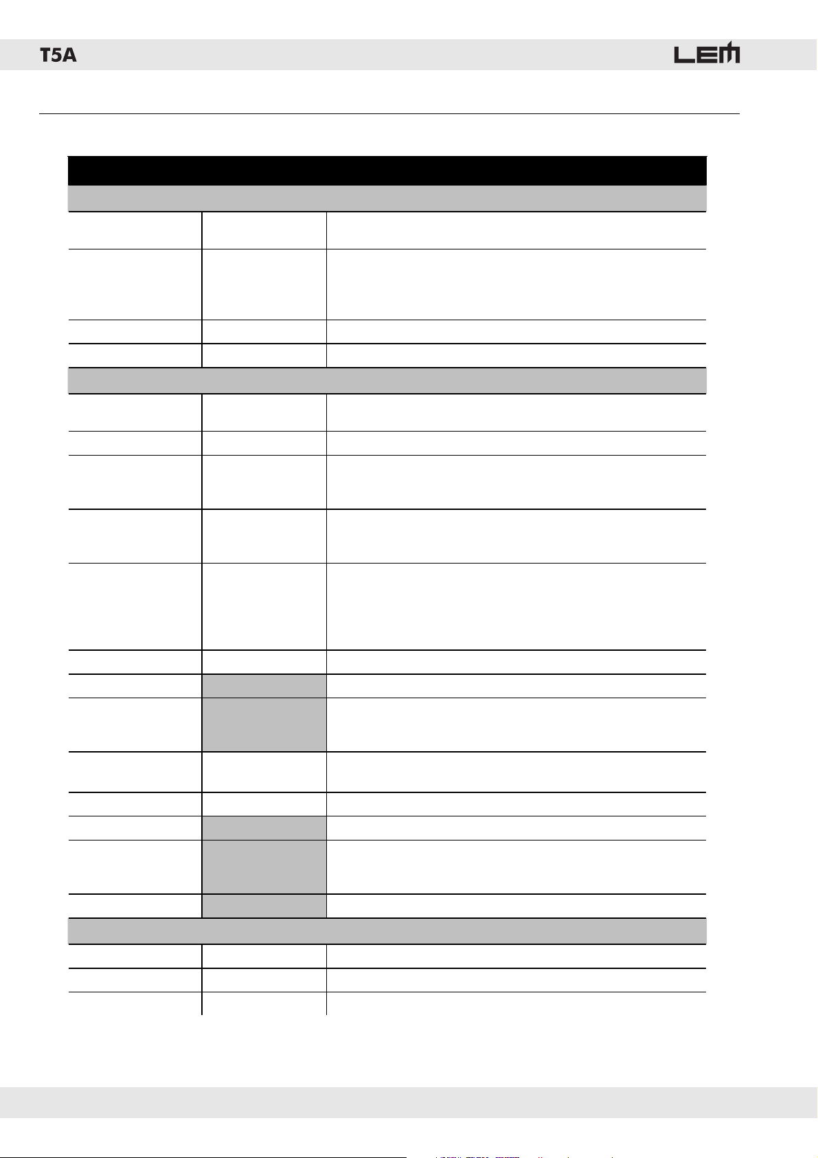
10. Technical specifi cations
T5A • TECHNICAL SPECIFICATIONS
Components
Construction
Transport and
Dimensions
Weight
Input
A/D converters
D/A converters
Crossover
EQ
Alignment delay
Plugins
Protections
Output power
EIA (1kHz, THD 1%)
Distortion
Controls
Connections
Power supply
mm (WxHxD) 456x690x430
impedance
Dynamic range
Sampling Rate
LOUDSPEAKER SPECIFICATIONS
High
Low
Cabinet
Protection
Installation
kg 32
Laminated birch plywood with black scratch-resistant paint
Metal handles and speaker stand adapter
1” driver with CD horn
15” woofer
Metal grid
AMPLIFIER SPECIFICATIONS
sensitivity
bit 24
bit
Typ e
Frequency
Slope
Number
Typ e
Gain
Bandwidth
Frequency
max delay 189 ms
W High
W Low
Peak, 6dB Lo-Shelf, 12dB Lo-Shelf, 6dB Hi-Shelf, 12dB Lo-Shelf, Notch
From 0.05 to 3.00 octaves, variable with 0.05dB step
Noise Gate, Anti-feedback, Multiband compressor
% <0.02
+4 dB (nominal) / -40dB (max)
20 kOhms (balanced)
24
100 dB
48 kHz
Bessel, Butterworth or Linkwitz-Riley
Variable from 15.6 Hz t 16 kHz
6, 12, 18 o 24 dB/oct.
25 parametric bands
+/-15dB, variable with 0.5dB step
From 15.6 Hz to 16 kHz
Independent PEAK LIMITER on each output
Long term power protection on each output
LFC - Low Frequency Control
100
400
Volume - PRESET selector
1 x COMBO (LINE + MIC input )
1 x XLR-M (link)
Connettore di alimentazione
see label
Frequency response
Sensitivity
Dispersion
SYSTEM SPECIFICATIONS
Hz (-10dB) 50 - 20000
MAX SPL Continuous 122
° 80 x 80
12
Page 13
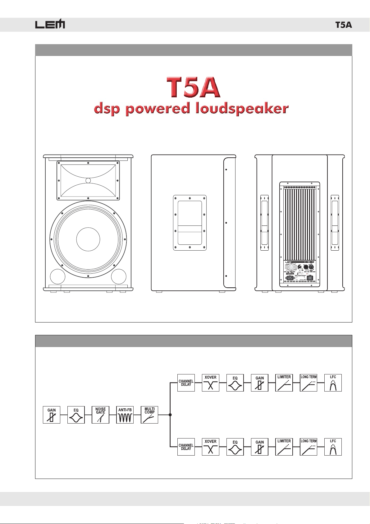
FIG. 1 - THE SYSTEM
FIG. 2 - DPPM BLOCK DIAGRAM
13
Page 14
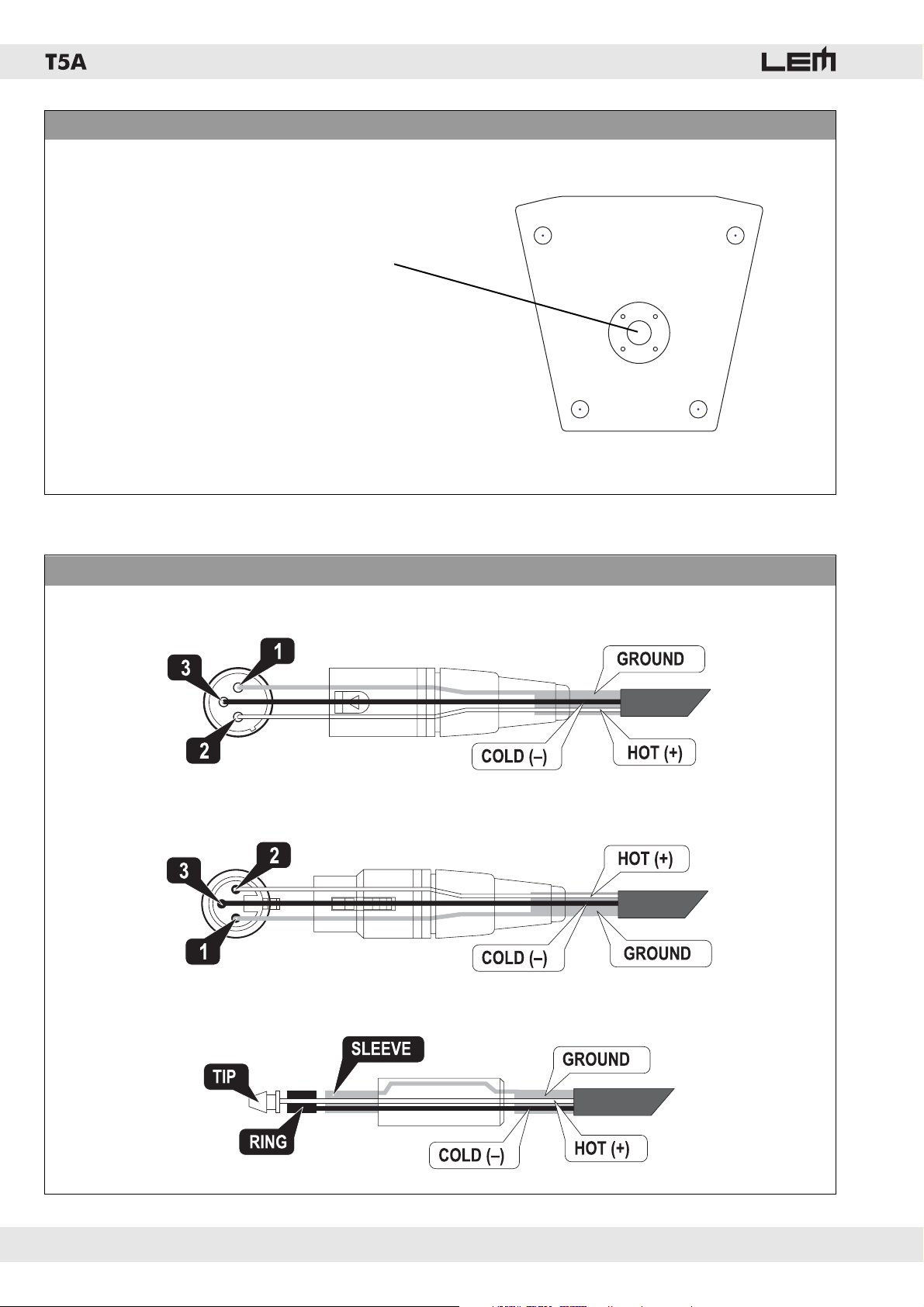
FIG. 3 - INSTALLATION
Speaker stand adaptor
FIG. 4 - CONNECTION CABLES
14
Page 15
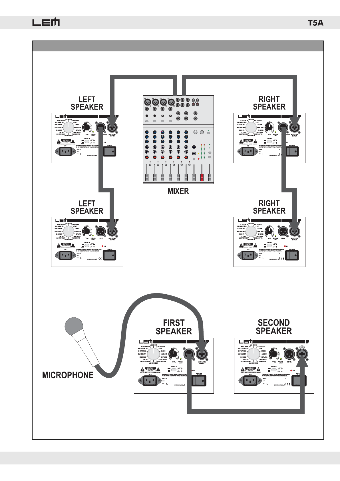
FIG. 5 - CONNECTIONS
15
Page 16
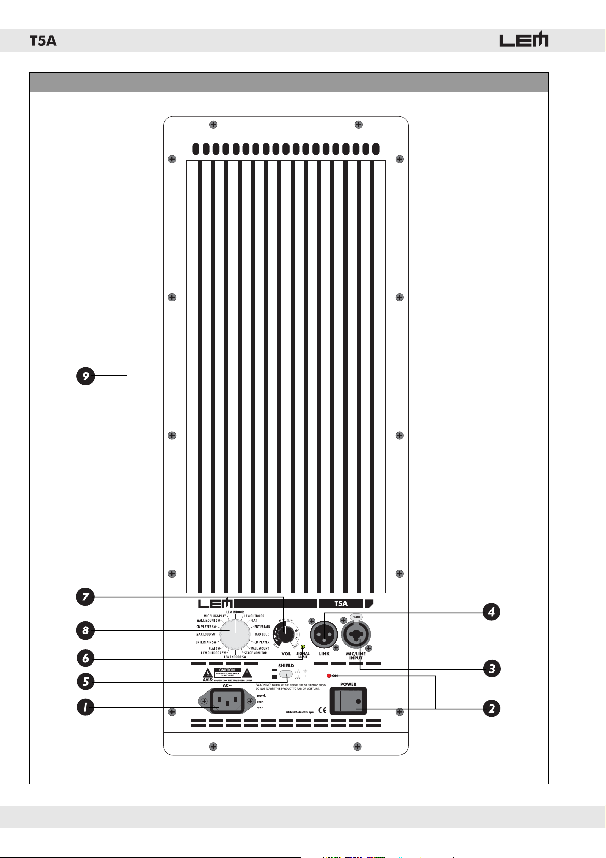
FIG. 6 - DPPM MODULE - Connection panel
16
Page 17
FEDERAL COMMUNICATIONS COMMISSION
NOTE: This equipment has been tested and found to comply with the limits for a Class A digital device,
pursuant to Part 15 of FCC Rules. These limits are designed to provide reasonable protection against harmful
interference when the equipment is operated in a commercial environment. This equipment generates, uses
and can radiate radio frequency energy and, if not installed and used in accordance with the instruction
manual, may cause harmful interference to radio communications. Operations of this equipment in a
residential area is likely to cause harmful interference in which case the user will be required to correct the
interference at his own expense.
CAUTION: Changes or modifi cations to this product not expressly approved by the manufacturer could void
the user's authority to operate this product.
Le informazioni contenute in questo documento sono state at ten ta men te redatte e controllate. Tuttavia non
è assunta alcuna re spon sa bi li tà per eventuali inesattezze.
Tutti i diritti sono riservati e questo documento non può essere copiato, fotocopiato, riprodotto per intero o
in parte senza previo consenso scritto della GENERALMUSIC S.p.A.
GENERALMUSIC si riserva il diritto di apportare senza preavviso cam bia men ti e modifi che estetiche,
funzionali o di design a ciascun proprio prodotto.
GENERALMUSIC non assume alcuna responsabilità sull’uso o sul l’ap pli ca zio ne dei prodotti o dei circuiti
qui descritti.
STAMPATO IN ITALIA
The information contained in this publication has been carefully prepared and checked. However no
responsibility will be taken for any errors.
All rights are reserved and this document cannot be copied, photocopied or reproduced in part or completely
without written consent being obtained in advance from GENERALMUSIC S.p.A.
GENERALMUSIC reserves the right to make any aesthetic, functional or design modifi cation to any of its
products without any prior notice.
GENERALMUSIC assumes no responsibility for the use or application of the products or circuits described
herein.
PRINTED IN ITALY
17
Page 18

 Loading...