

Page 1

Page 2

IMPORTANT SAFETY INSTRUCTIONS
INSTRUCTIONS PERTAINING TO A RISK OF FIRE, ELECTRIC SHOCK OR INJURY TO PERSONS
WARNING - When using electric products, basic precautions should always be followed, including
the following:
1. Read all the SAFETY INSTRUCTIONS before using the product.
2. To reduce the risk of injury, close supervision is necessary when the product is used near children.
3. Do not use this product near water - for example, near a bathtub, washbowl, kitchen sink, in a wet
basement or near a swimming poor or the like.
4. This product in combination with headphones or an amplifier, may be capable of producing sound
levels that could cause permanent hearing loss. Do not operate for a long period of time at high volume
level or at a level that is uncomfortable. If you experience any hearing loss or ringing in the ears, you
should consult an audiologist.
5. This product should be located so that its location or position does not interfere with its proper
ventilation.
6. This product should be located away from heat sources such as radiators, heat registers or other
products that produce heat.
7. The product should be connected to a power supply only of the type described on the operating
instructions or as marked on the product.
8. This product may be equipped with a polarized line plug (one blade wider than the other). This is a
safety feature. If you are unable to insert the plug into the outlet, contact an electrician to replace
your obsolete outlet. Do not defeat the safety purpose of the plug.
9. The power-supply cord of the product should be unplugged from the outlet when left unused for a
long period of time. When unplugging the power-supply cord, do not pull on the cord, but grasp it by
the plug.
10. Care should be taken so that object do not fall and liquid are not spilled into the enclosure through
openings.
11. The product should be serviced by qualified service personnel when:
A. The power-supply cord or the plug has been damaged; or
B. Objects have fallen, or liquid has been spilled into the product; or
C. The product has been exposed to rain; or
D. The product does not appear to operate normally or exhibits a marked change in performance; or
E. The product has been dropped or the enclosure damaged.
12. Do not attempt to service the product beyond that described in the user-maintenance instructions.
All other servicing should be referred to qualified service personnel.
13. WARNING - Do not place objects on the product's power cord or place it in a position where
anyone could trip over, walk on or roll anything over it. Do not allow the product to rest on or to be
installed over power cords of any type. Improper installations of this type create the possibility of fire
hazard and/or personal injury.
SAVE THESE INSTRUCTIONS
The lightning flash with arrowhead symbol within an
equilateral triangle is intended to alert the user to the
presence of uninsulated "dangerous voltage" within the
product's enclosure, that may be of sufficient magnitude to
constitute a risk of electric shock to persons.
The exclamation point within an equilateral triangle is
intended to alert the user to the presence of important
operating and maintenance (servicing) instructions in the
literature accompanying the appliance.
Page 3

rd 122 & rd 122 fx
3
1. Introduzione
Congratulazioni per l'acquisto del mixer rd 122!
Per un impiego corretto del mixer seguite le istruzioni
riportate in questo manuale. Buon divertimento e buon
lavoro.
2. Sommario
3. Norme di Installazione ed Uso . . . . . . . . . . 3
4. Canale di ingresso MONO . . . . . . . . . . . . . 3
5. Canale di ingresso STEREO . . . . . . . . . . . 4
6. Sezione MASTER . . . . . . . . . . . . . . . . . . . . 4
7. Pannello POSTERIORE . . . . . . . . . . . . . . . 5
8. 24bit Digital Effect Processor (rd 122 fx) . . 6
9. Specifiche Tecniche . . . . . . . . . . . . . . . . . . 7
3. Norme di Installazione ed Uso
1. La protezione e la manutenzione.
Evitate di collocare il mixer in vicinanza di forti fonti di
calore e di esporlo direttamente alla luce solare, alla
pioggia, all’umidità, alla polvere o ad intense vibrazioni.
Non forzate manopole, interruttori e cursori: sono
studiati per rispondere ad una leggera pressione e
potrebbero essere danneggiati se usati con forza
eccessiva. In caso di avaria non aprite il mixer, ma
rivolgetevi al più vicino Centro di Assistenza
GENERALMUSIC.
2. Prevenzione di possibili disturbi.
Verificate che il luogo di installazione non presenti
disturbi industriali o a radio frequenza. Evitate
comunque di installare la vostra apparecchiatura in
stretta prossimità di apparecchi radio, TV, telefoni
cellulari, etc., in quanto questi potrebbero causare
interferenze rumorose.
3. Collegamenti
Prima di collegare il mixer alla presa di corrente
accertatevi sempre che l’impianto elettrico e la presa
dispongano di un’appropriata messa a terra compatibile
con le norme di sicurezza. Accertatevi, inoltre, che la
tensione di rete corrisponda a quella indicata sul retro
dell’apparato (è accettata una tolleranza fino a ±10%)
e che il cavo di alimentazione non sia danneggiato e
non presenti fili scoperti. Per evitare pericolosi picchi
di segnale effettuate i collegamenti con altri apparati
sempre a mixer spento e accendete sempre prima il
mixer e poi gli amplificatori o i diffusori amplificati.
4. I cavi di collegamento
Per il collegamento del mixer agli amplificatori di
potenza o ai diffusori amplificati accertatevi di utilizzare
sempre e solo cavi di segnale schermati costituiti da due
fili più una calza che funge da schermo. L’utilizzo di cavi
non schermati potrebbe determinare l’insorgere di
fastidiosi ronzii e rumori di fondo. Verificate
periodicamente che i cavi impiegati siano in buono
stato, con le connessioni realizzate nel modo corretto
e con tutti i contatti in perfetta efficienza, in modo da
evitare inconvenienti come falsi contatti, rumori di
massa, scariche, ecc.
4. Canale di ingresso MONO (fig. 1)
1. MIC INPUT
XLR bilanciato: ingresso riservato all'utilizzo di
MICROFONI. Può ricevere una vasta gamma di segnali
bilanciati o sbilanciati a bassa impedenza, incluso il
segnale di microfoni a condensatore con alimentazione
a +48V (vedi Pannello posteriore).
2. LINE INPUT
JACK: ingresso di LINEA utilizzabile con i segnali
provenienti da tutte le apparecchiature con uscita ad
alto livello.
3. GAIN
Controllo di guadagno per la regolazione
dell'amplificazione del segnale in ingresso.
Il range è: MIC = 0/-60 dB, LINE = +15/-45 dB.
4. LO-CUT
Filtro PASSA-ALTO che consente di attenuare le
frequenze basse al di sotto dei 75 Hz con una pendenza
di 18 dB per ottava. Grazie a questo filtro è possibile
eliminare le frequenze subsoniche indesiderate, come ad
esempio il rimbombo dei microfoni o le risonanze del palco.
5. HIGH
Controllo per le frequenze ALTE: consente un
guadagno o un’attenuazione di 15 dB a 12 kHz con una
curva di tipo “SHELVING”.
6. MID
Controllo per le frequenze MEDIE: consente un guadagno
o una attenuazione di 15 dB da 100 Hz a 8 kHz con una
curva di tipo “PEAKING”. La frequenza di intervento può
essere selezionata con il potenziometro FREQ.
7. LOW
Controllo per le frequenze BASSE: consente un
guadagno o una attenuazione di 15 dB a 80 Hz con una
curva di tipo “SHELVING”.
8. AUX 1 pre
La mandata AUX 1, destinata all’utilizzo di monitors da
palco, è PRE–FADER e quindi invia verso l’esterno il
segnale prelevato prima del controllo di livello del
canale. In questo modo è possibile realizzare un
mixaggio per i monitors completamente indipendente
dal mixaggio principale.
Page 4

4
rd 122 & rd 122 fx
9. AUX 2 pre/post
La mandata AUX 2 può essere posizionata PRE o POSTFADER e, pertanto, può essere utilizzata a scelta per
l’impiego di monitors (PRE-FADER, missaggio indipendente
dal volume del canale) o di effetti esterni (POST-FADER,
missaggio dipendente dal volume del canale).
10. AUX 2 post
Tasto per la commutazione POST-FADER della
mandata AUX 2.
11. AUX 3 / DFX post
La mandata AUX 3 controlla un segnale POST FADER
e, quindi, può essere utilizzata come mandata per gli
EFFETTI esterni. Inoltre, nel modello RD122 FX la
mandata AUX 3 invia il segnale del canale all’effetto
digitale interno (DFX).
12. PAN
Potenziometro a scatto centrale per il controllo
panoramico (Left/Right) del segnale.
13. ALT 3-4
Tramite questo tasto è possibile sia escludere il segnale
del canale dal MAIN MIX (funzione MUTE) che
assegnarlo, in caso di necessità, ad un secondo master
stereo. Il master supplementare ALT 3-4 può essere
utilizzato per raggruppare un certo numero di segnali,
controllarli con un singolo slider e poi riassegnarli al
MAIN MIX tramite la funzione ALT 3-4 to MIX. Inoltre,
può essere utilizzato anche per inviare i segnali
assegnati verso una seconda uscita (ALT 3-4
OUTPUTS).
14. SOLO
Tramite questo tasto è possibile assegnare il segnale
del canale all’ascolto in cuffia, alle uscite CONTROL
ROOM e alla visualizzazione sui BARGRAPHS a LED.
A seconda della posizione del tasto SOLO MODE,
l’ascolto e la visualizzazione possono essere PRE (PFL)
o POST-FADER (AFL).
15. PEAK
LED di visualizzazione di picco del segnale: si accende
quando il livello del segnale del canale è prossimo al
massimo livello accettabile prima della distorsione.
16. LEVEL
Fader per il controllo del livello del canale.
5. Canale di ingresso STEREO (fig. 2)
1. STEREO INPUT
Connettori JACK che ricevono il segnale STEREO di
livello linea in ingresso. Inserendo un unico connettore
JACK nell’ingresso LEFT, il canale si comporta come
un canale MONO.
2. +4dB / -10dB
Controllo di guadagno per la selezione
dell'amplificazione del segnale in ingresso. I valori
disponibili sono:
a) +4dB: adatto in genere per apparecchi professionali
con uscita ad alto livello;
b) -10dB: adatto in genere ad apparati con uscita a
basso livello, come piastre di registrazione, alcuni lettori
CD ed altri strumenti.
3. HI-MID
Controllo per le frequenze MEDIO-ALTE: consente un
guadagno o una attenuazione di 15 a 8 kHz con una
curva di tipo “PEAKING”.
4. LO-MID
Controllo per le frequenze MEDIO-BASSE: consente un
guadagno o una attenuazione di 15 a 500Hz con una
curva di tipo “PEAKING”.
5. BAL
Controllo di bilanciamento del segnale verso le uscite
principali.
NOTA: le rimanenti funzioni del canale di ingresso
STEREO sono equivalenti a quelle già descritte per il
canale MONO
6. Sezione MASTER (fig. 3 - 4)
1. AUX SENDS
Connettori JACK sbilanciati: inviano verso l’esterno la
somma dei segnali provenienti dalle corrispondenti
mandate AUX dei canali di ingresso.
2. AUX RETURNS L(mono)-Right
Connettori JACK sbilanciati degli ingressi stereo
ausiliari. Possono essere utilizzati per il ritorno del
segnale da effetti esterni oppure per collegare
qualunque strumento o apparato con uscite di linea.
3. 2-TRACK input
Connettori RCA sbilanciati: sono i connettori degli
ingressi stereo per un registratore esterno (ad esempio
un DAT, un registratore a cassette o un registratore
MD).
4. 2-TRACK output
Connettori RCA sbilanciati: sono i connettori delle uscite
stereo del MIX L&R per un registratore esterno (ad
esempio una DAT, un registratore a cassette o un
registratore MD).
5. PHONES
Connettore JACK STEREO per l’uscita di cuffia:
collegate a questa uscita solo cuffie stereo con
impedenza minima di 200 Ohms.
Page 5

rd 122 & rd 122 fx
5
6. AUX SENDS
Potenziometri per il controllo del livello della somma dei
segnali provenienti dalle mandate AUX dei canali di
ingresso.
7. AUX 3/DFX RETURN
Potenziometro per il controllo del livello dell’ingresso
stereo AUX RETURN. Nel modello RD122 FX questo
potenziometro controlla anche il segnale proveniente
dall’effetto digitale interno verso il MAIN MIX.
8. AUX 3/DFX TO MONITOR
Potenziometro per il controllo del livello dell’ingresso
stereo AUX RETURN 3 e del segnale proveniente
dall’effetto digitale interno (modello RD122 FX) verso
la mandata AUX 1.
Consente di utilizzare l’effetto collegato all’AUX
RETURN 3 oppure l’effetto interno sulla mandata
monitor AUX 1.
Nota: nel modello RD122 FX, nel caso si desideri
utilizzare un effetto esterno al posto di quello interno,
è consigliabile metter quest’ultimo nella posizione di
MUTE.
9. AUX 1&2 RETURN
Potenziometri per il controllo del livello degli ingressi
stereo AUX RETURN 1 e 2.
10. SOLO MODE
Consente di scegliere se la modalità di ascolto e di
visualizzazione dei canali selezionati con il tasto SOLO:
a) PFL: PRE-FADER LEVEL, visualizza il segnale
presente in ingresso e regolato dall’EQ di canale. Da
utilizzare per regolare il livello corretto del segnale
senza distorsione (solitamente attorno al valore di 0dB).
b) AFL: POST FADER LEVEL, visualizza il segnale
controllato dal fader di canale. Da utilizzare per
ascoltare il segnale del canale inviato al MAIN MIX.
11. SOLO ACTIVE
LED di segnalazione dell’attivazione della funzione
SOLO: si accende quando viene attivato uno o più
pulsanti SOLO sui canali di ingresso con la modalità
AFL selezionata.
12. LEVEL SET
Questo LED si accende quando uno o più tasti SOLO
sono premuti ed è selezionata la modalità PFL. Questa
è la classica modalità di SOLO utilizzata per la
regolazione del livello di ingresso dei canali.
13. LEVEL
BARGRAPHS a 12 LED per la visualizzazione del livello
del segnale assegnato alle uscite MAIN MIX o
selezionato tramite i tasti SOLO oppure assegnato
tramite i tasti C.ROOM SOURCE.
I LEDs sono di 3 diversi colori:
• verde = indicano il normale livello operativo del
segnale (da -30 a +4 dB);
• giallo = indicano che il segnale si trova ad un livello
operativo elevato (da +7 a +10 dB);
• rosso (CLIP) = indicano che il segnale in uscita si trova
ad un livello troppo elevato, vicino al livello di
saturazione dello stadio di uscita del mixer.
14. MAIN MIX LEVEL
Slider stereo per il controllo del volume generale.
15. ALT 3-4 LEVEL
Slider stereo per il controllo del volume del master
supplementare ALT 3-4.
16. PHONES / C. ROOM LEVEL
Controllo di livello delle uscite cuffia e CONTROL
ROOM. Tramite i relativi tasti di assegnazione a queste
uscite è possibile assegnare il segnale del MAIN MIX,
del master supplementare ALT 3-4 e dell’ingresso 2TRK IN. Quando, però, viene premuto il pulsante SOLO
di uno o più canali, da queste uscite è possibile
ascoltare il segnale dei canali selezionati. A seconda
della posizione del tasto SOLO MODE, tale segnale può
essere PRE (PFL) o POST-FADER (AFL).
17. C. ROOM SOURCE
Tasti di assegnazione all’uscita PHONES / C.ROOM e
al bargraph a LED.
18. 2-TRK TO MIX
Tasto di assegnazione dell’ingresso 2-TRACK al MAIN MIX.
19. ALT 3-4 TO MIX
Tasto di assegnazione del master supplementare ALT
3-4 al MAIN MIX. Grazie a questo tasto è possibile
utilizzare il master supplementare ALT 3-4 come SUBGROUP per raggruppare e controllare simultaneamente
più canali di ingresso.
20. ON
LED di segnalazione dell’accensione del mixer.
21. +48V
LED di segnalazione dell’attivazione della alimentazione
phantom +48 Volt.
7. Pannello POSTERIORE (fig. 5)
1. MAIN MIX XLR OUTPUTS
Due connettori XLR-M bilanciati (+4 dB). Uscite
principali del mixer: inviano all'esterno il programma
principale proveniente dal MAIN MIX.
2. MAIN MIX JACK OUTPUTS
Due connettori JACK sbilanciati (+4 dB). Sono i
connettori ausiliari delle uscite principali del mixer e
inviano all'esterno il programma principale proveniente
dal MAIN MIX.
Page 6

6
rd 122 & rd 122 fx
8. 24bit Digital Effect Processor (rd 122
fx)
Realizzato con tecnologia LEM a 24 bit, il processore
di effetti riceve il segnale direttamente dalle mandate
AUX 3 / DFX dei canali. L’uso è di estrema facilità.
1. PRESETS
Selettore che consente di scegliere tra 16 diverse
tipologie di effetti: riverberi di varia natura, delay mono
o stereo, effetti modulati, combinazioni di due effetti.
2. VARIATIONS
Selettore che consente di scegliere tra 16 diverse
varianti (durata, profondità, contenuto armonico, etc.)
della tipologia di effetto selezionata con PRESETS.
La presenza di 16 varianti per ciascun PRESET
consente di avere a disposizione 256 effetti diversi. I
parametri principali di ciascun effetto sono riportati nella
tabella RD 122 FX PRESET LIST (pagg. 18 e 19)
3. MUTE
Tasto per l’attivazione o la disattivazione (MUTE)
dell’effetto.
NOTA: l’effetto può essere attivato/disattivato anche
attraverso un controllo a pedale collegato alla presa
DSP FOOTSWITCH.
4. LED PEAK/MUTE
Questo LED segnala due condizioni:
• luce fissa = indica la condizione di MUTE dell’effetto.
• lampeggiante = indica che il segnale inviato all’effetto
è prossimo al massimo livello
accettabile prima della distorsione.
3. MAIN MIX INSERTS
Connettori JACK STEREO: consentono l’utilizzo di una
apparecchiatura esterna per il trattamento del segnale
(equalizzatore, compressore, ecc.) sul MAIN MIX. I
connettori di INSERT presentano la mandata (SEND)
sulla punta (TIP) ed il ritorno (RETURN) sull’anello
(RING) (vedi CAVI DI COLLEGAMENTO)
4. C. ROOM OUTPUTS
Due connettori JACK sbilanciati (0dB): inviano
all’esterno il segnale dei canali selezionati tramite la
funzione SOLO oppure (quando nessun tasto SOLO è
premuto) i segnali selezionati nella sezione C. ROOM
SOURCE. Questa uscita può essere utilizzata per il
monitoraggio o anche come master ausiliario.
5. ALT 3-4 OUTPUTS
Due connettori JACK sbilanciati (0db): inviano
all’esterno il segnale dei canali selezionati tramite la
funzione ALT 3-4. Questa uscita può essere utilizzata
come master ausiliario.
6. DSP FOOTSWITCH - solo rd 122 fx
Permette di collegare un controllo a pedale col quale
attivare/disattivare il Digital Effect Processor interno.
7. CHANNEL INSERTS
Connettori JACK STEREO: consentono l’utilizzo di una
apparecchiatura esterna per il trattamento del segnale
(equalizzatore, compressore, ecc.) sui canali di ingresso
da 1 a 8. I connettori di INSERT presentano la mandata
(SEND) sulla punta (TIP) ed il ritorno (RETURN)
sull’anello (RING) (vedi CAVI DI COLLEGAMENTO)
8. +48V
Tasto per l’assegnazione dell’alimentazione PHANTOM
+48 Volt alle prese XLR dei canali mono.
NOTA
Quando attivate l’alimentazione PHANTOM assicuratevi
di utilizzare SEMPRE per il collegamento dei microfoni
cavi con connettori XLR BILANCIATI, in modo da
evitare danneggiamenti anche quando vengono utilizzati
contemporaneamente sia microfoni a condensatore, sia
microfoni convenzionali (dinamici). Attivate
l’alimentazione PHANTOM solo dopo aver collegato il
microfono all’ingresso e solo con il volume di canale
chiuso per evitare picchi di segnale in uscita.
9. POWER
Interruttore di accensione/spegnimento del mixer.
10. Presa di rete / Alloggiamento fusibile
principale
In caso di rottura del fusibile, sostituitelo sempre con
uno dello stesso tipo e dello stesso valore.
Page 7

rd 122 & rd 122 fx
7
sensibilità
da 0 a -60dB
impedenza
1.5 kohms
sensibilità
da +15 a -45dB
impedenza
10 kohms
Low cut
75Hz, 18dB/oct.
HIGH
+/-15dB @12kHz
MID
+/-15dB da 100Hz a 8kHz
LOW
+/-15dB @80Hz
sensibilità
-10dB/+4dB
impedenza
10 kohms
HIGH
+/-15dB @12kHz
HI-MID
+/-15dB @8kHz
LO-MID
+/-15dB @500Hz
LOW
+/-15dB @80Hz
Uscita MIX (bilanciata)
livello di uscit a
+4dB XLR-M bilanciato
Uscita MIX (sbilanciata)
livello di uscit a
0dB JACK sbilanciato
Uscita ALT 3-4
livello di uscit a
0dB JACK sbilanciato
Uscita CONTROL ROOM
livello di uscit a
0dB JACK sbilanciato
Mandate AUX
livello di uscit a
0dB JACK sbilanciato
Ritorni AUX
sensibilità
0dB JACK sbilanciato
IN
0dB
OUT
0dB
impedenza minima
200 ohms
livello di uscit a
2x193mW
Convertitori A/D e D/A
Risoluzione DSP
Tip i di effetto
Presets
Controlli
Risposta in frequenza da 10Hz a 55kHz, +/-3dB
Hum & Noise -93dBu
THD <0.005% a +4dBu, 1kHz
IMD <0.005% a +4dBu, 1kHz
Diafonia
FADER
PAN
-82dBu
-82dBu
Liv elli
MIC IN
TAPE IN
altri ingressi
MIX OUT (XLR)
altre uscite
+22dBu
+22dBu
+22dBu
+28dBu
+22dBu
Alimentazione vedi etichetta
Peso
kg
6.0
Dimensioni
mm (LxAxP)
392 x 392 x 80
SEZIONE DSP
RD 122 • SPECIFICHE TECNICHE
Ingresso MIC XLR-F bilanciato
Ingresso LINE JACK bilanciato
TAPE RCA phono
Uscita di CUFFIA JACK stereo
256
Selettore a 16 posizioni PRESET BANK
Selettore a 16 posizioni VARIATION
CLIP LED
Tasto MUTE con indicatore a LED
SPECIFICHE GENERALI
24 bit
24 bit
RIVERBERI Hall, Room, Vocal & Plate
Mono & Stereo DELAY (max DELAY TIME 500ms)
MODULAZIONI Chorus, Flanger & Vibrato
Combinazioni REV+DELAY, REV+CHORUS, REV+FLANGER, REV+VIBRATO
SEZIONE MASTER
CANALI DI INGRESSO STEREO (5-8)
CANALI DI INGRESSO MONO (1-8)
EQ
JACK bilanciatoIngresso STEREO LINE
EQ
Page 8

8
rd 122 & rd 122 fx
1. Introduction
Congratulations for having chosen the rd 122 mixer!
To make the best use of the mixer, please read this
manual thoroughly before operating the equipment.
2. Contents
3. Instructions for use and installation . . . . . . 8
4. MONO input channel . . . . . . . . . . . . . . . . . . 8
5. STEREO input channel . . . . . . . . . . . . . . . . 9
6. MASTER section . . . . . . . . . . . . . . . . . . . . . 9
7. REAR panel . . . . . . . . . . . . . . . . . . . . . . . . 10
8. 24bit Digital Effect Processor . . . . . . . . . . 11
9. Technical Specifications . . . . . . . . . . . . . . 12
3. Instructions for use and installation
1. Protection and maintenance.
To avoid jeopardizing correct operation, it is best not
to position the mixer for long periods in exposed places
(damp, high temperature, etc.), in dusty environments
or those subject to strong vibrations. Do not force
knobs, switches or faders: they have been designed to
respond to a light touch and could be damaged if
treated with excessive force. In the event of breakdown,
do not open the mixer, but contact the nearest
GENERALMUSIC Service Centre.
2. Prevention of possible interference.
First of all, check that the mixer is installed in a place
free from industrial or RF (radio frequency) interference.
Avoid installing your equipment very near radio or TV
sets, mobile phones, etc., as these can cause noisy
interference.
3. Connections.
Before connecting the amplifier to the mains socket,
always make certain that the electric system and mains
socket have an adequate grounding, compatible with
the safety norms. Be sure also that the mains voltage
corresponds to that shown on the rear of the unit (an
allowance of up to ±10% is accepted) and that the
power cord is not damaged and has no bare wires. It
is best to lower (or better still close) the output levels
and switch off any amplifiers connected to the line
output of the mixer before switching the mixer on or off:
this avoids annoying and sometimes dangerous
(particularly for the speaker cabinets) signal peaks.
4. Connector cables.
When connecting the mixer to the amplifiers or the
amplified speakers, make certain to always use only
screened signal cables made up of two wires plus a
braid/screen: the use of unscreened cables could in fact
probably cause annoying hum and noise. Check
periodically that your cables are in good condition,
correctly wired and with perfectly efficient contacts: in
fact many problems and drawbacks (false contacts,
ground hum, crackles, etc.) are caused by the use of
unsuitable or damaged cables.
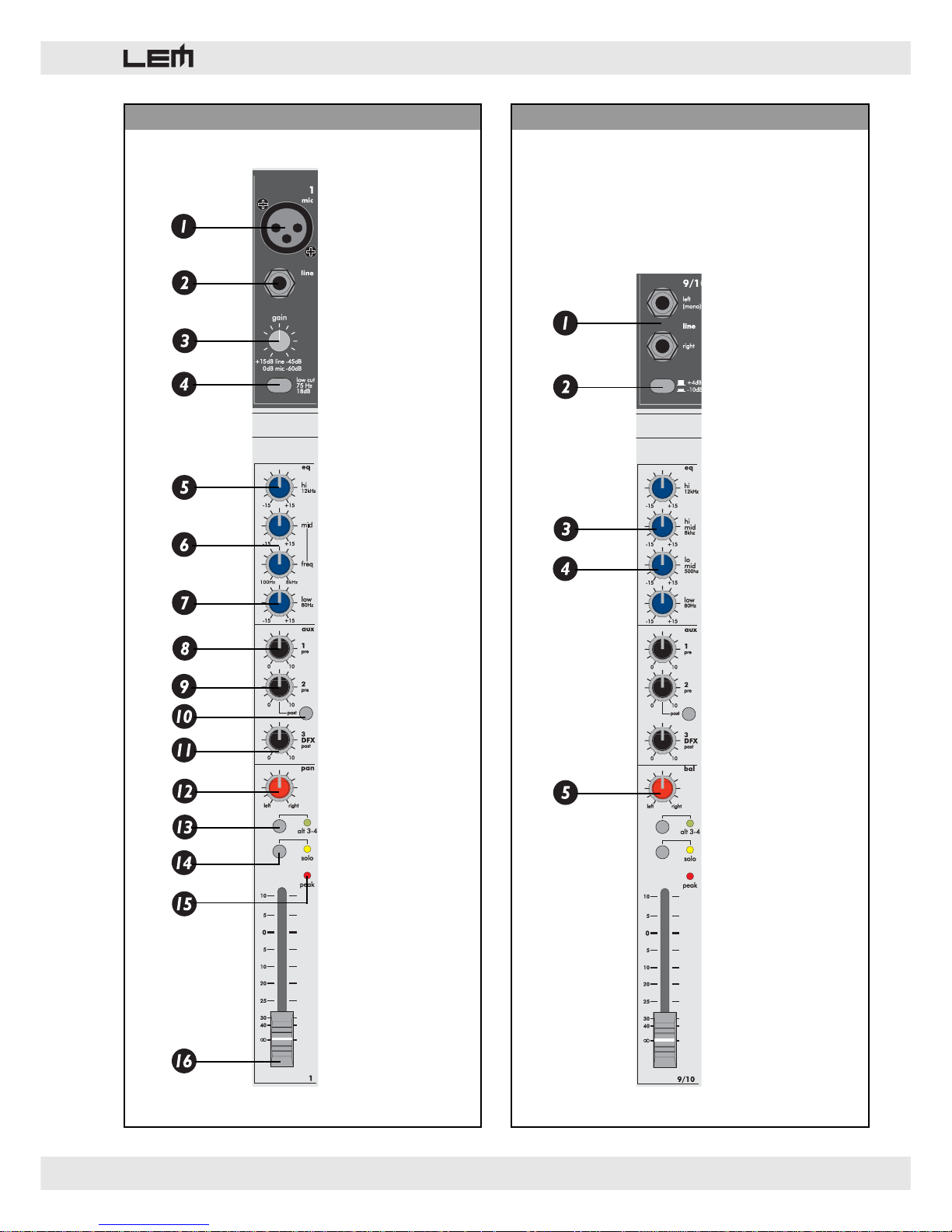
4. MONO input channel (pic. 1)
1. MIC INPUT
Balanced XLR: this input receives the MICROPHONE
signal on the channel and can accept a wide range of
balanced or unbalanced low impedance signals,
including the signal coming from condenser
microphones with +48V power supply (see Rear panel).
2. LINE INPUT
JACK: this input can receive high-impedance signals
from equipment with a LINE output.
3. GAIN
Gain control of the amplification of external signals fed
into the channel.
The range is: MIC = 0/-60 dB, LINE = +15/-45 dB.
4. LO-CUT
HI-PASS filter that allows to reduce the frequencies
below 75 Hz with a 18 dB / Oct. slope. Thanks to this
filter it’s possible to eliminate unwanted subsonic
frequencies, like, for examples the microphones rumble
due to the stage resonance.
5. HIGH
HIGH frequency control: gives a 15dB boost or cut at
12 kHz with a “SHELVING” curve.
6. MID
MID frequency control: gives 15dB boost or cut from
100 Hz to 8 kHz with a “PEAKING” curve. The EQ
frequency can be selected using the FREQ control.
7. LOW
LOW frequency control: gives 15dB boost or cut at 80Hz
with a “SHELVING” curve.
8. AUX 1 pre
The AUX 1 send, provided for the use with with stage
monitors, is PRE-FADER: this means than the signal sent
to the MONITORS is taken before the control of the
channel FADER, allowing a completely independent mix
for the monitoring respect to the main mix.
9. AUX 2 pre/post
The AUX 2 can be set as PRE or POST FADER and,
therefore, it can be used as a MONITOR (PRE-FADER,
mix independent from the channel level) or EFFECT
(POST-FADER, mix dependent from the channel level)
send.
Page 9

rd 122 & rd 122 fx
9
4. LO-MID
LO-MID frequency control: gives 15dB boost or cut at
500 Hz with a “PEAKING” curve.
5. BAL
Centre-dented control of the balance of the signal on
the main outputs.
NOTE: the remaining features of the STEREO channel
are the same as in the MONO channel.
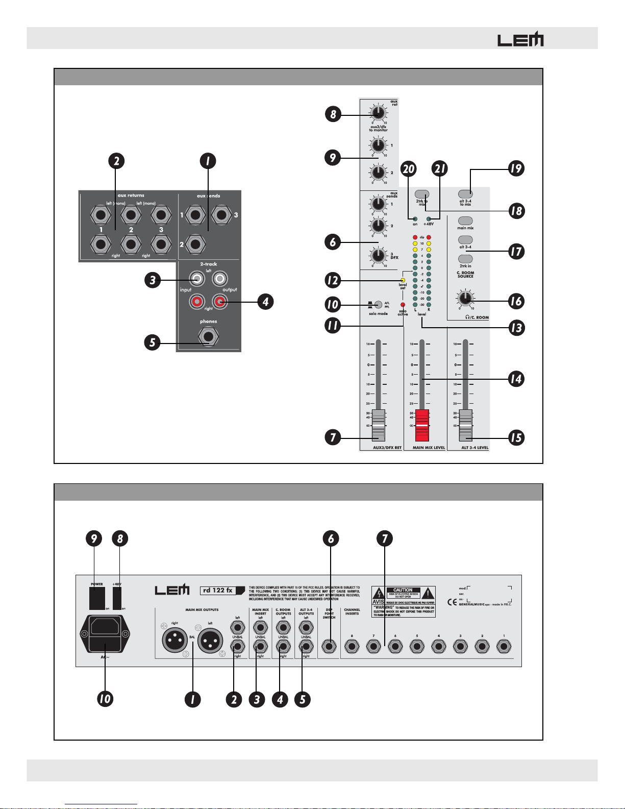
6. MASTER section (pic 3 - 4)
1. AUX SENDS
Unbalanced JACK connectors: feed out the sum of the
signals arriving from the relative AUX sends of the input
channels.
2. AUX RETURNS L(mono)-Right
Unbalanced JACK connectors: these are the connectors
of the auxiliary stereo inputs. These inputs can be used
for the return signal from outboard effects or for
connecting any instrument or equipment with a line
output
3. 2-TRACK input
Two RCA connectors: receive external signals from
STEREO tape recorders, CD player, DAT, etc.
4. 2-TRACK output
Two RCA connectors: send out the signal taken from
MIX and normally intended for STEREO recording.
5. PHONES
STEREO JACK headphone output connector: only
stereo headphones with a minimum impedance of 200
Ohms should be connected to this output.
6. AUX SENDS
Pot for controlling the level of the signals coming from
the AUX sends of the input channels.
7. AUX 3 / DFX RETURN
Slider for controlling the level of the AUX RETURN 3
stereo input. In the RD122 FX model this slider controls
also the signal coming from the built-in digital effect and
fed to the MAIN MIX.
8. AUX 3 / DFX TO MONITOR
Pot for controlling the level of the AUX RETURN 3 and
the signal coming form the built-in effect (RD122 FX
model) to the AUX 1 send.
Allows the effect connected to the AUX RETURN 2 to
be used on the MONITOR AUX 1.
Note: in the RD122 FX model, if you need to use an
external effect instead of using the internal one, it’s
better to MUTE the built-in effect.
10. AUX 2 post
Button for setting the AUX 2 send POST-FADER.
11. AUX 3 / DFX post
The AUX 3 controls a POST-FADER signal and,
therefore, can be used for external EFFECTS. In
addition, in the RD122 FX model the AUX 3 sends the
signal to the built-in digital effect (DFX).
12. PAN
Centre-dented pot for controlling the signal’s pan.
13. ALT 3-4
Using this button the channel signal can be excluded
from the MAIN MIX (MUTE function) and, at the same
time, it can be assigned to a different stereo mix. The
ALT 3-4 mix can be used to group and to control with
a single fader a number of channel and to route them
to the MAIN MIX or to e dedicated stereo output (ALT
3-4 OUTPUTS).
12. SOLO
Allows the channel signal to be selected for the listening
thru the HEADPHONES outputs, the CONTROL ROOM
outputs and the visualization on the LED BARGRAPHS.
According to the position of the SOLO MODE switch,
the listening and the visualization can be PRE- (PFL)
or POST-FADER (AFL).
11. PEAK
PEAK LED indicator: lights up when the input signal is
near to the CLIPPING point.
13. LEVEL
Fader for controlling channel level.
5. STEREO input channel (pic 2)
1. STEREO INPUT
JACK connector that receives the STEREO LINE input
signal on the channel. Inserting a single JACK
connector on the LEFT socket this channel can be used
as a MONO channel.
2. +4dB / -10dB
Sensitivity selector for setting the amplification of
external signals fed into the channel. The values
available are:
a) +4dB: suitable for professional units with high level
output;
b) -10dB: suitable for low-level output units, such as
tape players, some CD players and other instruments.
3.HI- MID
HI-MID frequency control: gives 15dB boost or cut at 8
kHz with a “PEAKING” curve.
Page 10

10
rd 122 & rd 122 fx
9. AUX 1&2 RETURNS
Pot for controlling the level of the AUX RETURN 1 and
2.
10. SOLO MODE
Allows to select if the listening and the visualization of
the channels selected with the SOLO buttons are PREFADER (PFL) or POST FADER (AFL).
a) PFL : PRE-FADER LEVEL, the input signal, already
controlled by the channel EQ, is shown on the LED
bargraphs and sent to the headphones output. The PFL
mode has to be used for setting the right level for the
input signal (usually around 0dB) and to avoid
distortions.
b) AFL : AFTER-FADER LEVEL, the input signal,
already controlled by the channel EQ and by the
channel fader, is shown on the LED bargraphs and sent
to the headphones output. The AFL mode can be used
to listen the signal sent to the MAIN MIX.
11. SOLO ACTIVE
Indicates when at least one SOLO button is pressed on
the input channels and when the AFL MODE is
selected.
12. LEVEL SET
This LED lights when one or more SOLO button are
pressed and the PFL mode is selected. This is the typical
SOLO mode used to set the input level of the channels.
13. LEVEL
12-LED BARGRAPHS for the visualization of the signal
assigned to the MAIN MIX outputs, the signal of the
channels selected by the SOLO buttons or the signal
selected in the C. ROOM SOURCE section.
The LEDs are of three different colors:
• green = show the normal operative level of the signal
(from -30 to +4 dB);
• yellow = show a high operative level of the signal
(from +7 to +10 dB);
• red (CLIP) = show a too high signal level, near to the
overload of the mixer output stage.
14. MAIN MIX LEVEL
Slider for control of the general volume.
15. ALT 3-4 LEVEL
Slider for control of the volume of the ALT 3-4 mix.
16. PHONES / C. ROOM LEVEL
Slider for controlling the level of the HEADPHONES
outputs and of the CONTROL ROOM outputs.
Using the C. ROOM SOURCE buttons, it’s possible to
assign to these outputs the signal coming from the
MAIN MIX, from the ALT 3-4 mix and from the 2-TRK
input.
When one or more SOLO buttons on the input channels
are pressed, the signal of the selected channels can be
heard from the headphones and control room outputs.
According to the position of the SOLO MODE switch,
this signal can be PRE- (PFL) or POST-FADER (AFL).
17. C. ROOM SOURCE
Buttons for assigning the signal to the headphones and
control room outputs and to the LED bargraph.
18. 2-TRK TO MIX
This button assigns the signal coming from the 2-TRK
input to the MAIN MIX.
19. ALT 3-4 TO MIX
This button assigns the signal coming from the ALT 34 mix to the MAIN MIX. Thanks to this button, the ALT
3-4 mix can be used as a stereo sub-group.
20. ON
LED indicating when the mixer is switched on.
21. +48V
LED indicating when the +48V phantom power is
switched on.
7. REAR panel (pic 5)
1. MAIN MIX XLR OUTPUTS
Two balanced XLR-M connectors (+4 dB). These are
the MAIN MIX balanced outputs.
2. MAIN MIX JACK OUTPUTS
Two unbalanced JACK connectors (+4 dB). These are
the MAIN MIX unbalanced outputs.
3. MAIN MIX INSERTS
STEREO JACK connectors: allow to use an external
device (equalizer, compressor, etc.) to process the
signal of the MAIN MIX. The INSERT connectors are
placed on the rear panel of the mixer and they have
the signal SEND on the JACK TIP and the signal
RETURN on the JACK RING (see CONNECTOR
CABLES).
4. C. ROOM OUTPUTS
Two unbalanced JACK connectors (+4dB): send out the
signal of the channel selected with the SOLO or (when
no SOLO button is pressed) the signals selected in the
C. ROOM SOURCE section. This output can be used
for monitoring or as an auxiliary bus.
5. ALT 3-4 OUTPUTS
Two unbalanced JACK connectors (+4dB): send out the
signal of the channel selected with the ALT 3-4 buttons.
This output can be used as an auxiliary bus.
6. DSP FOOTSWITCH - rd 122 fx only
Allows to connect a footswitch to turn on/off the built-in
Digital Effect Processor.
Page 11
rd 122 & rd 122 fx
11
7. CHANNEL INSERTS
STEREO JACK connectors: allow to use an external
device (equalizer, compressor, etc.) to process the
signal of the input channels from 1 to 8. The INSERT
connectors are placed on the rear panel of the mixer
and they have the signal SEND on the JACK TIP and
the signal RETURN on the JACK RING (see
CONNECTOR CABLES).
8. +48V
+48V Phantom power supply buttons: activates +48V
power supply on the MIC inputs of the MONO input
channels.
NOTE
When the PHANTOM power supply is needed, make
certain that cables with BALANCED XLR connectors are
ALWAYS used to connect the microphones: this
precaution is extremely important for avoiding damage
in the event of both condenser and normal (dynamic)
microphones being used simultaneously. Switch on the
PHANTOM power supply only after having connected
the condenser microphone to the input and only with
the channel fader closed to avoid output signal peaks.
5. POWER
Mixer on/off switch.
6. Power supply socket / Main fuse holder
In the event of breaking, always replace the fuse with
same type and rating.
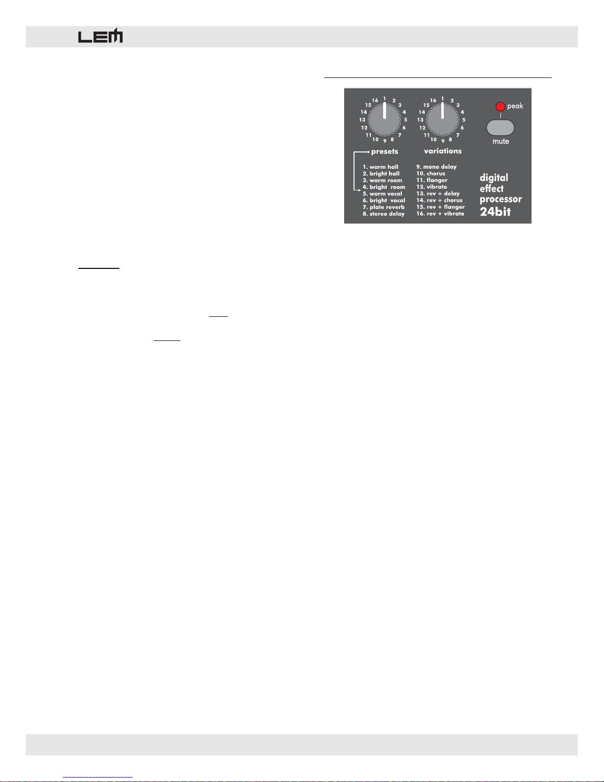
8. 24bit Digital Effect Processor (rd 122 fx)
Built on 24 bit LEM technology, the onboard Digital
Effect Processor receives the signal sent by the AUX
3 / DFX sends of the channels.
Use couldn’t be easier.
1. PRESETS
Allows to select the desired effect among 16 types:
several kinds of reverb, mono or stereo delay, effects
with modulation, 2-effect combinations.
2. VARIATIONS
Allows to choice the desired variation (decay, depth,
harmonic content, etc.) among 16 VARIATIONS of the
selected PRESET. The presence of 16 VARIATIONS
for each PRESETS allows up to 256 different effects
to be available. The main parameters of each effect
are listed in the RD 122 FX PRESET LIST table (pages
18 and 19).
3. MUTE
Effect on/off switch.
NOTE: the effect can be turned on/off also by means
of a footswitch connected to the DSP FOOTSWITCH
socket.
4. PEAK/MUTE LED
This LED shows 2 conditions:
• lighted = shows the effect is MUTED.
• flashing = shows a too high signal level, near to the
overload of the mixer output stage.
Page 12
12
rd 122 & rd 122 fx
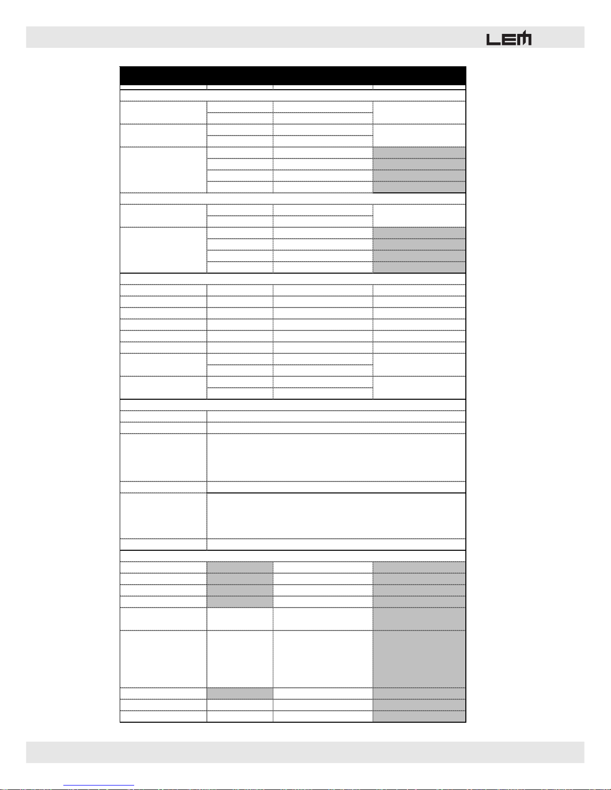
sensitivity
0 to -60dB
impedance
1.5 kohms
sensitivity
+15 to -45dB
impedance
10 kohms
Low cut
75Hz, 18dB/oct.
HIGH
+/-15dB @12kHz
MID
+/-15dB da 100Hz a 8kHz
LOW
+/-15dB @80Hz
sensitivity
-10dB/+4dB
impedance
10 kohms
HIGH
+/-15dB @12kHz
HI-MID
+/-15dB @8kHz
LO-MID
+/-15dB @500Hz
LOW
+/-15dB @80Hz
MIX output (balanced)
output level
+4dB Balanced XLR-M
MIX output (unbalanced)
output level
0dB Unbalanced JACK
ALT 3-4 output
output level
0dB Unbalanced JACK
CONTROL ROOM output
output level
0dB Unbalanced JACK
AUX sends
output level
0dB Unbalanced JACK
AUX return
sensitivity
0dB Unbalanced JACK
IN
0dB
OUT
0dB
minimum impedance
200 ohms
output level
2x193mW
A/D and D/A Converters
DSP resolution
Type of effects
Presets
Controls
CONTROL ROOM output
Frequency response 10Hz to 55kHz, +/-3dB
Hum & Noise -93dBu
THD <0.005% at +4dBu, 1kHz
IMD <0.005% at +4dBu, 1kHz
Crosstalk
FADER
PAN
-82dBu
-82dBu
Maximum levels
MIC IN
TAPE IN
other inputs
MIX OUT (XLR)
other outputs
+22dBu
+22dBu
+22dBu
+28dBu
+22dBu
Power supply see label
Weight
kg
6.0
Dimensions
mm (WxHxD)
392 x 392 x 80
MASTER SECTION
STEREO INPUT CHANNELS (5-8)
MONO INPUT CHANNELS (1-4)
EQ
Balanced JACKSTEREO LINE input
EQ
256
16-position PRESET BANK selector
16-position VARIATION selector
CLIP LED
MUTE SWITCH with LED indicator
+4dB
GENERAL SPECIFICATIONS
24 bit
24 bit
Hall, Room, Vocal & Plate REVERBS
Mono & Stereo DELAY (max DELAY TIME 500ms)
Chorus, Flanger & Vibrato MODULATIONS
REV+DELAY, REV+CHORUS, REV+FLANGER, REV+VIBRATO combinations
TAPE RCA phono
HEADPHONES output Stereo JACK
DSP SECTION (RD 82 FX version)
RD 122 • TECHNICAL SPECIFICATIONS
MIC input Balanced XLR-F
LINE input Balanced JACK
Page 13
rd 122 & rd 122 fx
13
PIC/FIG. 1 - MONO INPUT CHANNEL PIC/FIG. 2 - STEREO INPUT CHANNEL
Page 14
14
rd 122 & rd 122 fx
PIC/FIG. 5 - REAR PANEL
PIC/FIG. 3-4 - MASTER SECTION
Page 15
rd 122 & rd 122 fx
15
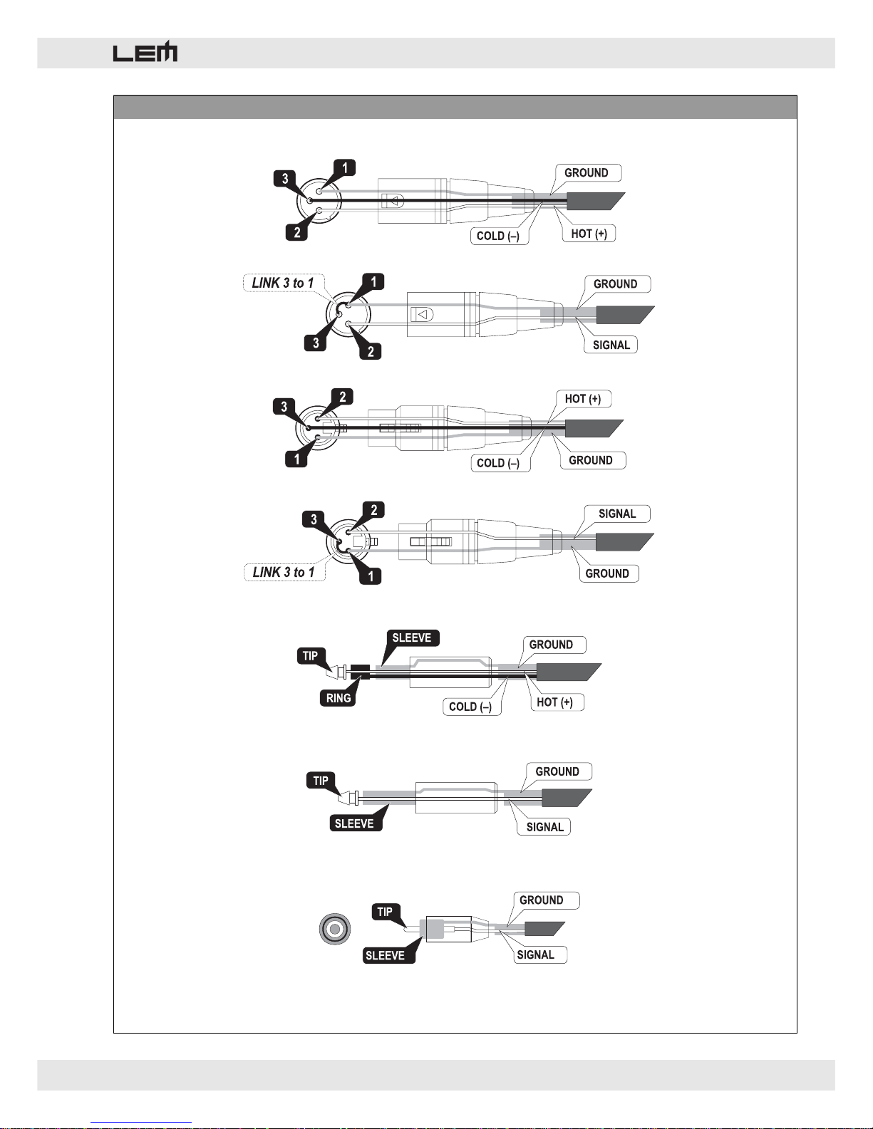
PIC/FIG. 6 - CONNECTORS
XLR-M bal
XLR-M bilanciato
XLR-M unbal
XLR-M sbilanciato
XLR-F bal
XLR-F bilanciato
XLR-M unbal
XLR-F sbilanciato
JACK bal
JACK bilanciato
JACK unbal
JACK sbilanciato
RCA (unbal)
RCA (sbilanciato)
Page 16
16
rd 122 & rd 122 fx
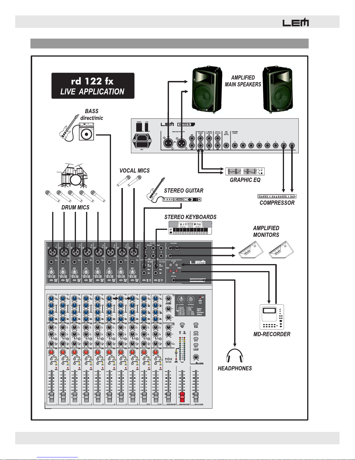
PIC/FIG. 7 - LIVE CONNECTION EXAMPLE
Page 17
rd 122 & rd 122 fx
17
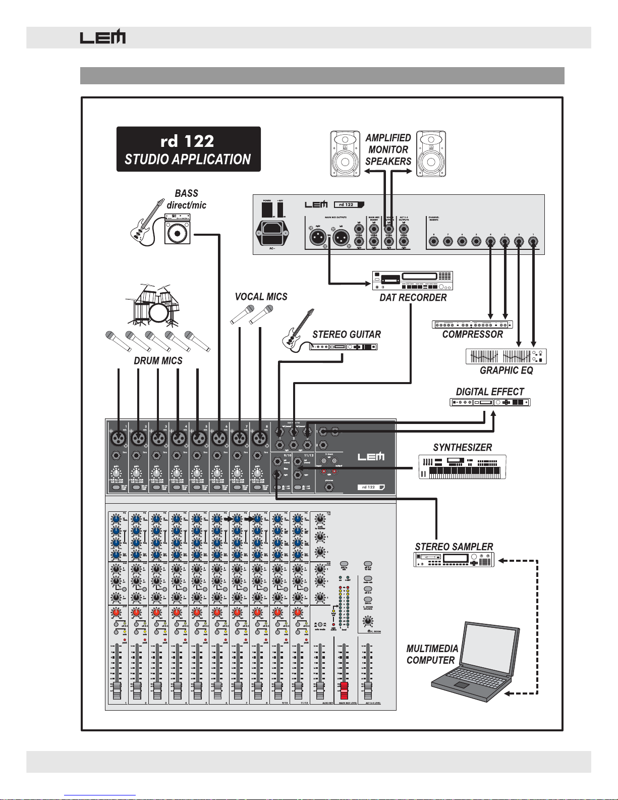
PIC/FIG. 8 - STUDIO CONNECTION EXAMPLE
Page 18
18
rd 122 & rd 122 fx
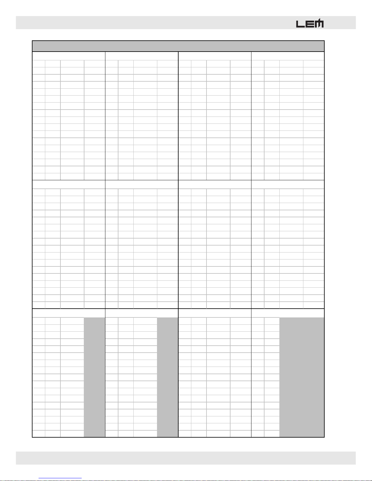
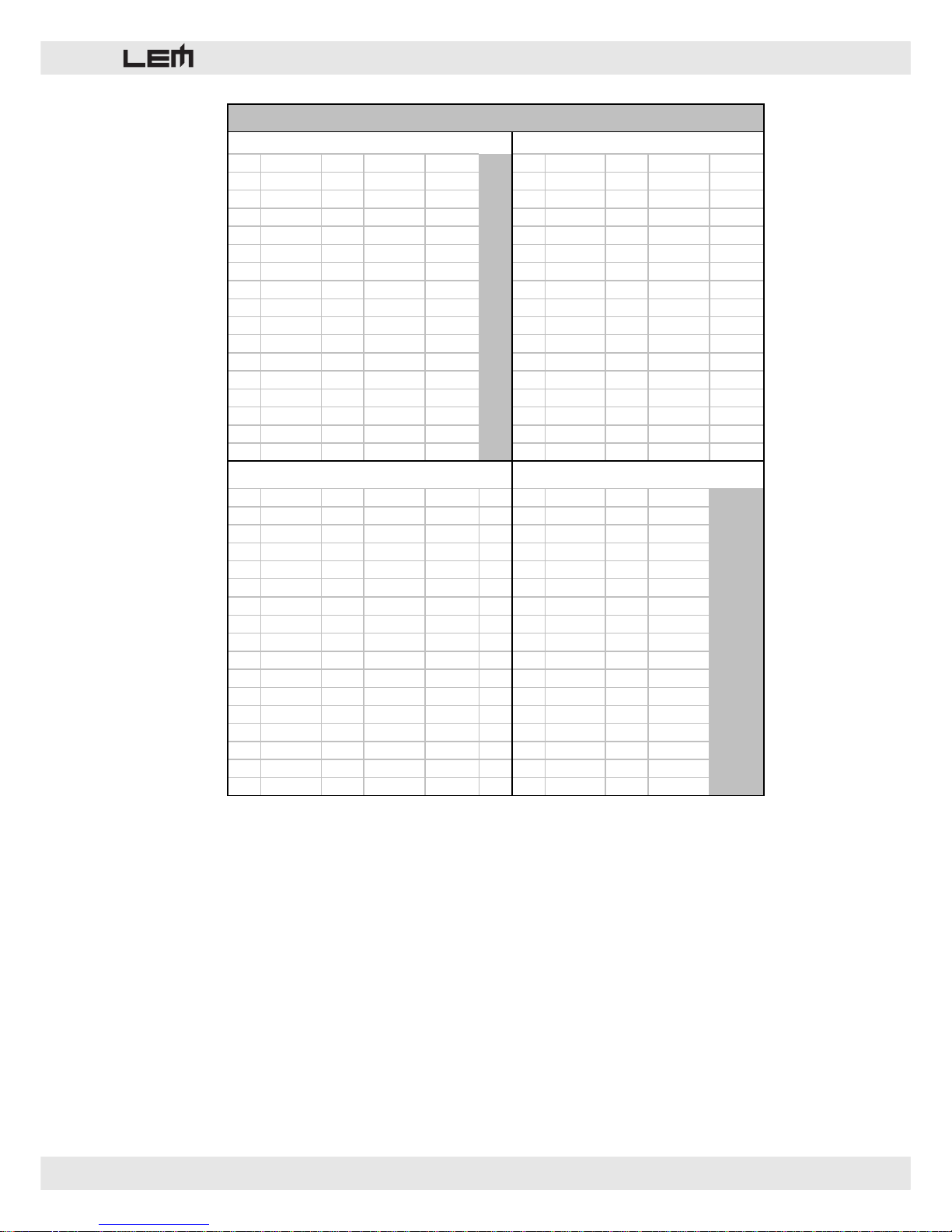
01.WARM HALL REV 02.BRIGHT HALL REV 03.WARM ROOM REV 04.BRIGHT ROOM REV
No. PD Rev Time Room No. PD Rev Time Room No. PD Rev Time Room No. PD Rev Time Room
1 20 1.00 25 1 20 1.00 25 1 20 0.70 8 1 20 0.70 8
2 20 1.50 26 2 20 1.50 26 2 20 1.00 8 2 20 1.00 8
3 20 2.10 27 3 20 2.10 27 3 20 1.50 9 3 20 1.50 9
4 23 2.90 28 4 23 2.90 28 4 23 2.10 9 4 23 2.10 9
5 23 3.60 30 5 23 3.60 30 5 23 2.90 10 5 23 2.90 10
6 27 4.00 32 6 27 4.00 32 6 27 3.60 10 6 27 3,60 10
7 27 4.50 33 7 27 4.50 33 7 27 4.00 11 7 27 4.00 11
8 40 5.40 35 8 40 5.40 35 8 40 4.50 11 8 40 4.50 11
9 40 1.00 36 9 40 1.00 36 9 40 0.70 16 9 40 0.70 16
10 40 1.50 37 10 40 1.50 37 10 40 1.00 16 10 40 1.00 16
11 40 2.10 38 11 40 2.10 38 11 40 1.50 17 11 40 1.50 17
12 45 2.90 39 12 45 2.90 39 12 45 2.10 17 12 45 2.10 17
13 45 3.60 41 13 45 3.60 41 13 45 2.90 18 13 45 2.90 18
14 50 4.00 42 14 50 4.00 42 14 50 3.60 18 14 50 3.60 18
15 50 4.50 43 15 50 4.50 43 15 50 4.00 19 15 50 4.00 19
16 55 5.40 45 16 55 5.40 45 16 55 4.50 20 16 55 4.50 20
05.WARM VOCAL REV 06.BRIGHT VOCAL REV
No. PD Rev Time Room No. PD Rev Time Room No. PD Rev Time Room No.
DelayR Delay L/R F.B.
1 10 1,20 9 1 10 1,20 9 1 10 0.60 10 1 214 107 37/73
2 25 2,40 9 2 25 2,40 9 2 10 0.70 10 2 222 111 38/73
3 40 1,00 45 3 40 1,00 45 3 10 0.80 10 3 230 115 37/73
4 84 1,00 39 4 84 1,00 39 4 10 1.00 10 4 238 119 36/73
5 79 3,60 8 5 79 3,60 8 5 10 1.20 10 5 241 120 36/73
6 0 0,90 41 6 0 1,00 41 6 10 1.30 10 6 250 125 37/73
7 50 2,10 9 7 50 2,10 9 7 10 1.50 10 7 258 129 38/73
8 30 1,00 8 8 30 1,00 8 8 10 1.70 10 8 267 133 30/66
9 45 0,8 41 9 45 0,80 41 9 10 2.10 10 9 277 138 40/66
10 45 1,50 41 10 45 1,50 41 10 10 2.40 10 10 288 144 40/66
11 45 4,50 10 11 45 4,50 10 11 10 2.90 10 11 300 150 40/72
12 0 4,50 10 12 0 4,50 10 12 10 3.60 10 12 312 156 40/72
13 114 1,00 10 13 114 1,00 10 13 10 4.00 10 13 326 163 40/72
14 114 1,00 10 14 114 1,00 10 14 10 4.50 10 14 352 176 40/72
15 55 1,70 11 15 55 1,70 11 15 10 5.40 10 15 375 187 51/72
16 55 3,60 11 16 55 3,60 11 16 10 6.10 10 16 400 200 51/72
No. Delay F.B. No. Freq. Depth No. Freq. Depth L/R F.B. No. Freq.
1 60 0 1 0.50 70 1 0.16 70 68/72 1 0.77
2 100 0 2 1.00 70 2 0.42 70 68/72 2 0.95
3 250 65 3 1.35 40 3 0.54 70 68/72 3 1.22
4 350 60 4 1.70 40 4 0.65 70 58/62 4 1.45
5 434 60 5 1.99 40 5 0.80 70 62/58 5 1.72
6 448 60 6 2.33 40 6 1.00 70 62/58 6 1.91
7 461 60 7 2.63 40 7 1.22 70 58/62 7 2.29
8 484 60 8 2.87 30 8 1.34 50 42/38 8 2.67
9 500 60 9 3.02 30 9 1.61 50 38/42 9 2.90
10 517 60 10 3.32 30 10 1.75 40 42/38 10 3.17
11 535 60 11 3.67 30 11 1.99 40 38/42 11 3.36
12 555 60 12 3.90 30 12 2.10 40 42/38 12 3.51
13 577 60 13 4.12 15 13 2.25 40 38/42 13 3.74
14 600 60 14 4.39 15 14 2.33 40 38/42 14 3.97
15 625 60 15 4.74 15 15 2.52 40 42/38 15 4.42
16 650 60 16 5.00 15 16 2.79 30 38/42 16 4.88
09.MONO DELAY 10.CHORUS 11.FLANGER
RD 122 FX - PRESET LIST
12.VIBRATO
08.STEREO DELA
Y
07.PLATE REV
Page 19
rd 122 & rd 122 fx
19
No. Rev Time Room L/R Delay L/R F.B. No. Rev Time Room Freq. Depth
1 1,00 26 211/107 28/49 1 1,50 26 0,50 70
2 1,00 26 230/115 28/49 2 1,50 26 1,35 70
3 1,50 26 241/120 28/49 3 1,50 26 1,99 40
4 1,50 26 258/129 28/60 4 1,50 26 2,63 40
5 1,50 26 277/138 28/67 5 1,50 26 3,02 40
6 1,50 26 300/150 28/67 6 1,50 26 3,67 40
7 2,10 26 326/163 28/67 7 1,50 26 4,12 40
8 2,10 26 375/187 48/82 8 1,50 26 4,74 40
9 2,40 39 211/107 28/49 9 2,90 39 0,50 70
10 2,40 39 230/115 28/49 10 2,90 39 1,35 70
11 2,40 39 241/120 28/49 11 2,90 39 1,99 40
12 2,40 39 258/129 28/60 12 2,90 39 2,63 40
13 2,90 39 277/138 28/67 13 2,90 39 3,02 40
14 2,90 39 300/150 28/67 14 2,90 39 3,67 40
15 2,90 39 326/163 28/67 15 2,90 39 4,12 40
16 2,90 39 375/187 48/82 16 2,90 39 4,74 40
No. Rev Time Room Freq. Depth F.B. No. Rev Time Room Freq.
1 1,50 26 0.16 70 70 1 1,50 26 0.77
2 1,50 26 0,54 70 70 2 1,50 26 1,22
3 1,50 26 0,80 70 60 3 1,50 26 1,72
4 1,50 26 1,22 70 60 4 1,50 26 2,29
5 1,50 26 1,61 50 40 5 1,50 26 2,90
6 1,50 26 1,99 40 40 6 1,50 26 3,36
7 1,50 26 2,25 40 40 7 1,50 26 3,74
8 1,50 26 2,52 40 40 8 1,50 26 4,42
9 2,90 39 0.16 70 70 9 2,90 39 0.77
10 2,90 39 0,54 70 70 10 2,90 39 1,22
11 2,90 39 0,80 70 60 11 2,90 39 1,72
12 2,90 39 1,22 70 60 12 2,90 39 2,29
13 2,90 39 1,61 50 40 13 2,90 39 2,90
14 2,90 39 1,99 40 40 14 2,90 39 3,36
15 2,90 39 2,25 40 40 15 2,90 39 3,74
16 2,90 39 2,52 40 40 16 2,90 39 4,42
14.REVERB + CHORUS
15.REVERB + FLANGER
RD 122 FX - PRESET LIST
13.REVERB + DELAY
16.REVERB + VIBRATO
Page 20
20
rd 122 & rd 122 fx
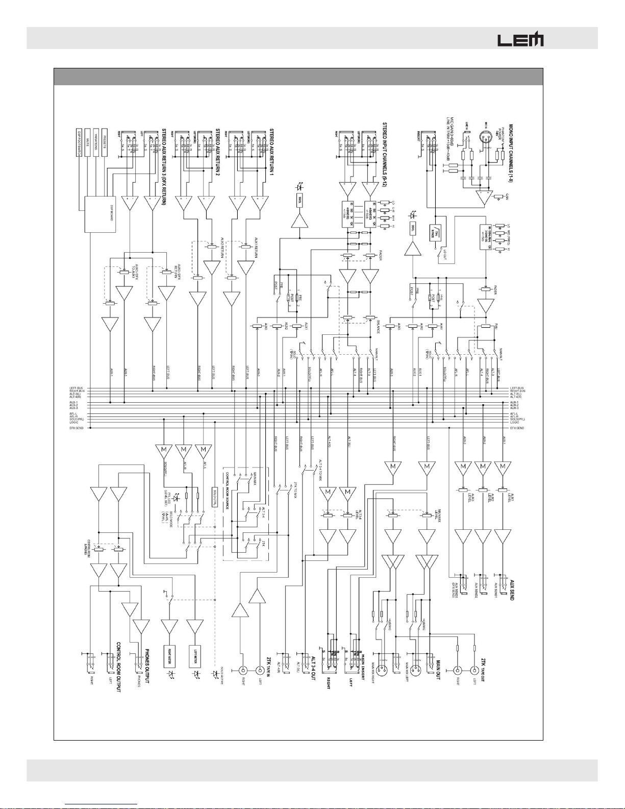
PIC/FIG. 9 - BLOCK DIAGRAM
Page 21

Le informazioni contenute in questo documento sono state attentamente redatte e controllate. Tuttavia
non è assunta alcuna responsabilità per eventuali inesattezze.
Tutti i diritti sono riservati e questo documento non può essere copiato, fotocopiato, riprodotto per intero o
in parte senza previo consenso scritto della GENERALMUSIC S.p.A.
GENERALMUSIC si riserva il diritto di apportare senza preavviso cambiamenti e modifiche estetiche,
funzionali o di design a ciascun proprio prodotto.
GENERALMUSIC non assume alcuna responsabilità sull’uso o sull’applicazione dei prodotti o dei circuiti
qui descritti.
STAMPATO IN ITALIA
The information contained in this publication has been carefully prepared and checked. However no
responsibility will be taken for any errors.
All rights are reserved and this document cannot be copied, photocopied or reproduced in part or completely
without written consent being obtained in advance from GENERALMUSIC S.p.A.
GENERALMUSIC reserves the right to make any aesthetic, functional or design modification to any of its
products without any prior notice.
GENERALMUSIC assumes no responsibility for the use or application of the products or circuits described
herein.
PRINTED IN ITALY
FEDERAL COMMUNICATIONS COMMISSION
NOTE: This equipment has been tested and found to comply with the limits for a Class A digital device,
pursuant to Part 15 of FCC Rules. These limits are designed to provide reasonable protection against
harmful interference when the equipment is operated in a commercial environment. This equipment
generates, uses and can radiate radio frequency energy and, if not installed and used in accordance with
the instruction manual, may cause harmful interference to radio communications. Operations of this
equipment in a residential area is likely to cause harmful interference in which case the user will be required
to correct the interference at his own expense.
CAUTION: Changes or modifications to this product not expressly approved by the manufacturer could
void the user's authority to operate this product.
Page 22

Sales Division: 47842 S.Giovanni in Marignano (RN) – Via delle Rose, 12 – tel. +39-0541-959511 – fax +39-0541-957404
Internet: http://www.lemaudio.com
 Loading...