

Page 1
r
Operating Instructions
Power Analyze
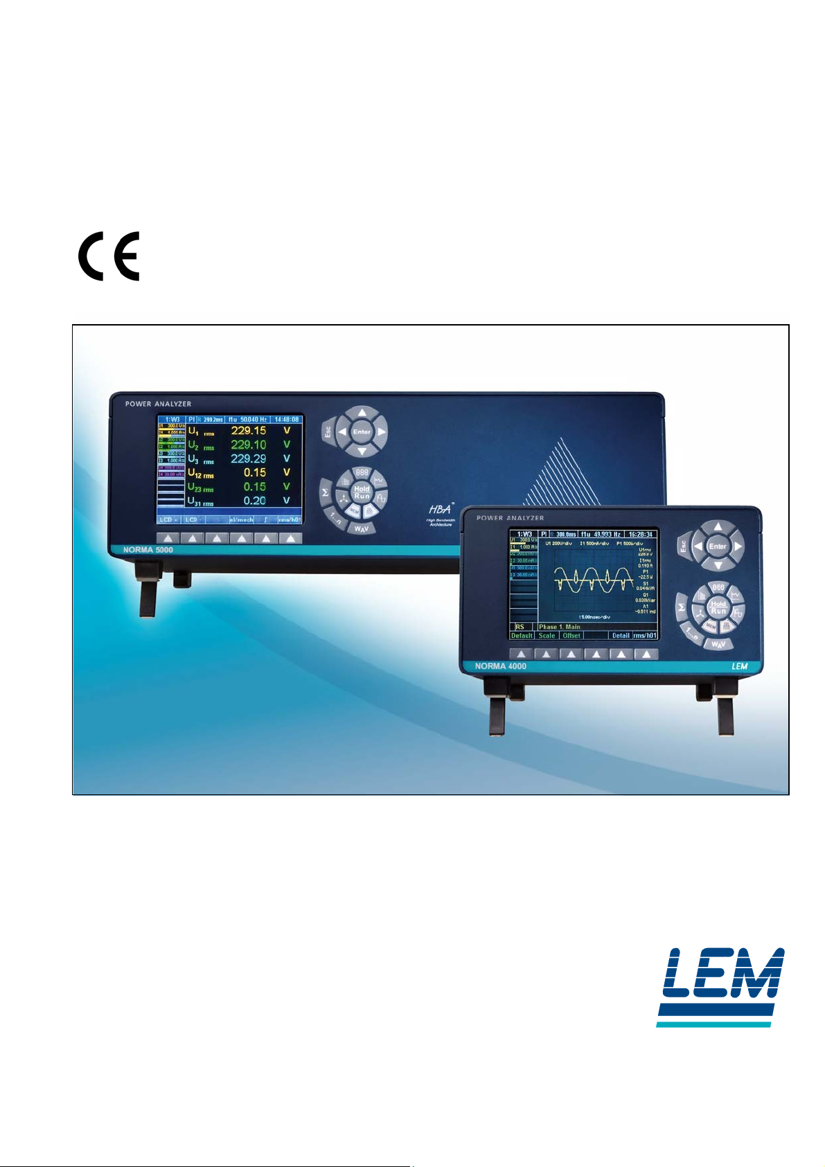
NORMA 4000
LEM NORMA GmbH
Liebermannstraße F01
CAMPUS 21
A-2345 Brunn am Gebirge
AUSTRIA
Tel.: +43(0)2236-691-0
E-Mail: [email protected]
Internet: www.lem.com
NORMA 5000
Page 2

Order no.: EO1111G
Version: Revision G
Date: 08 / 2005
The technical data contained in this document is subject to
changes without prior notice, due to continued product
development and improvements made by the manufacturer.
© LEM NORMA GmbH, All rights reserved.
Page 3

Contents
Contents
1 About this Document ......................................................................................... 3
1.1 Document structure..................................................................................... 3
1.2 Signs and symbols ...................................................................................... 3
2 General Safety Instructions ............................................................................... 4
2.1 Safety instructions on the device housing.................................................... 6
3 Design and functions ......................................................................................... 7
3.1 Terminals (rear of housing).......................................................................... 7
3.2 Operating controls and display .................................................................... 8
3.3 Functions................................................................................................... 10
4 Startup............................................................................................................... 11
4.1 Checking of delivery .................................................................................. 11
4.2 Installation and switching on...................................................................... 11
5 Connection to Circuits ..................................................................................... 12
5.1 Connecting sequence................................................................................ 12
5.2 Overview ................................................................................................... 12
5.3 1-phase measurement............................................................................... 13
5.3.1 Direct connection.......................................................................... 13
5.3.2 With shunt..................................................................................... 14
5.3.3 With voltage and current transducer ............................................. 15
5.4 Aron circuit (triaxial/guard technique)......................................................... 16
5.4.1 Direct connection.......................................................................... 16
5.4.2 With shunt..................................................................................... 17
5.4.3 With voltage and current transducer ............................................. 18
5.5 3-phase measurement in 4-wire system .................................................... 19
5.5.1 Direct connection.......................................................................... 19
5.5.2 With shunt..................................................................................... 20
6 Simple Measurement........................................................................................ 21
7 Configuration.................................................................................................... 22
7.1 Call up General Setup / Call up system information screen ....................... 23
7.2 Load configuration..................................................................................... 23
7.3 Configure data transfer to printer and PC .................................................. 23
7.4 Configure average time and synchronisation............................................. 26
7.5 Adjust date and time.................................................................................. 29
7.6 Configure current and voltage channels .................................................... 30
7.7 Switch current input to external input (BNC).............................................. 33
7.8 Integration function configuration............................................................... 34
7.9 Save configuration..................................................................................... 37
7.10 Delete configuration................................................................................... 37
7.11 Undersampling / Aliasing........................................................................... 37
8 Measuring process........................................................................................... 39
8.1 Prior to measuring..................................................................................... 39
8.2 Measure voltage, current and power ......................................................... 40
8.2.1 View the measured values for the individual channels .................. 40
8.2.2 View totals of all measured values................................................ 42
8.2.3 Compare measured values........................................................... 43
8.2.4 View fundamentals ....................................................................... 44
8.2.5 User defined screen view.............................................................. 45
Power Analyzer NORMA 4000, NORMA 5000 1
EO1111G REV G
Page 4

Contents
8.3 Change view mode.................................................................................... 47
8.3.1 Numerical display ......................................................................... 47
8.3.2 Vector graphs ............................................................................... 47
8.3.3 Oscilloscope curves...................................................................... 48
8.3.4 Recorder view............................................................................... 49
8.4 Fast Fourier analysis ................................................................................. 50
8.4.1 FFT mode ..................................................................................... 50
8.4.2 Harmonic Order mode .................................................................. 52
8.4.3 Harmonic Order mode related to fundamental in %....................... 53
8.5 Integration function / electrical work........................................................... 54
8.6 Save and print measurements................................................................... 56
8.6.1 Save measurements..................................................................... 56
8.6.2 Print measurements...................................................................... 56
9 PI1 Process Interface (optional) ...................................................................... 57
9.1 Pin assignment.......................................................................................... 57
9.2 Measured values ....................................................................................... 57
9.3 Configuring PI1.......................................................................................... 58
9.4 Measuring with PI1.................................................................................... 61
9.5 PI1 - technical data.................................................................................... 63
9.5.1 8 inputs (analog/digital)................................................................. 63
9.5.2 4 digital inputs for the detection of the sense of rotation................ 63
9.5.3 4 outputs (analog)......................................................................... 64
10 Formulas ........................................................................................................... 65
10.1 Direct current............................................................................................. 65
10.2 Alternating current ..................................................................................... 65
10.3 Fundamental and harmonics ..................................................................... 66
10.4 Frequency analysis.................................................................................... 66
10.5 Uncertainty of measurement...................................................................... 66
11 Transport and Storage ..................................................................................... 67
11.1 Transport................................................................................................... 67
11.2 Storage...................................................................................................... 67
12 Warranty............................................................................................................ 67
13 Recalibration..................................................................................................... 67
14 Maintenance...................................................................................................... 67
15 Decommissioning and Disposal...................................................................... 68
15.1 Shutting down............................................................................................ 68
15.2 Recycling and disposal.............................................................................. 68
15.3 Packaging.................................................................................................. 68
15.4 Housing ..................................................................................................... 68
15.5 Electronic components .............................................................................. 68
16 Technical Data .................................................................................................. 69
16.1 Technical data NORMA 4000.................................................................... 69
16.2 Technical data NORMA 5000.................................................................... 72
16.3 Block diagrams.......................................................................................... 75
17 Service and Accessories.................................................................................. 78
17.1 Instrument ................................................................................................. 78
17.2 Accessories............................................................................................... 79
17.3 Service ...................................................................................................... 79
2 Power Analyzer NORMA 4000, NORMA 5000
EO1111G REV G
Page 5
About this Document
1 About this Document
1.1 Document structure
This document consists of several chapters. Within these chapters,
shoulder headings in the margin identify sections in the text
focussing on the respective topic or procedure. Example:
"View details"
Symbols
Text formats
The text belonging to this shoulder heading informs you on how
the details of a measured value can be viewed, including
introductory notes, safety instructions, hints and tips, instructions
on procedures, figures and tables, if any.
1.2 Signs and symbols
The following signs and symbols are used in this document:
Symbol Description
...
...
...
– or –
...
Format Description
... identifies a requirement.
This requirement must be met before you can
proceed with the task described in this section of
the text.
... identifies a mandatory action.
You are requested to carry out a specified task.
... identifies a mandatory action to which there is
an alternative procedure. The alternative
procedure is introduced with "– or –" or by a left
indent.
... identifies general information and hints.
In the related section of the text, you find
important information regarding a certain system
feature or procedure.
... identifies important information.
The related information and instructions must
always be strictly followed.
... identifies a warning relating to a risk to life and
limb from electric shock.
If the instructions are not strictly adhered to,
there is an inevitable risk to life and limb.
... identifies a warning relating to a potential risk
or dangerous situation.
If the instructions are not adhered to, there is a
risk of death, injury or damage to property.
Detail
Power Analyzer NORMA 4000, NORMA 5000 3
EO1111G REV G
Names of software and operating elements,
lettering on the device as well as numbers and
text shown on the display are printed in italics.
Page 6

General Safety Instructions
2 General Safety Instructions
The design and manufacture of this device conform to the latest
state of technology and the safety standards laid down in IEC
61010-1/ 2nd edition. If used improperly, there is a risk of damage
to persons and property.
Protection class
Qualified
personnel
Safe operation
Proper use
Warranty
Electrical
connections
The device is assigned to protection class I according to IEC
61010-1 and is equipped with a protective earth connector.
The device may only be operated by suitably qualified
personnel.
For the purpose of these instructions, all persons who are familiar
with the installation, assembly, connection, inspection of
connections and operation of the analyzer and who have
completed training in at least one of the following areas:
- switching on/off, enabling, earthing and identification of
electrical circuits and devices/systems according to the
applicable safety standards;
- maintenance and operation of appropriate safety gear, in
accordance with the applicable safety standards;
- first aid.
Ensure that all persons using the device have read and fully
understood the operating manual and safety instructions.
The device may only be used under certain ambient
conditions. Ensure that the actual ambient conditions conform
to the admissible conditions laid down in chapter "Technical
data".
During operation, ensure that the cooling vents are not
obstructed.
Always comply with the instructions in chapter "Transport and
storage".
Do not use the device for any other purpose than the
measuring of voltages and currents that are within the
measuring ranges and categories, including voltage to earth,
laid down in chapter "Technical Data".
Improper use shall void all warranty.
The warranty period for fault free operation is limited to
2 years from the date of purchase.
The warranty period for accuracy is 2 years.
Ensure that the power and connecting cables used with the
device are in proper working order.
Ensure that the protective earth connector of the power lead is
connected according to the instructions to the low-resistance
unit earth cable.
Ensure that the power and connecting cables as well as all
accessories used in conjunction with the device are in proper
working order and clean.
4 Power Analyzer NORMA 4000, NORMA 5000
EO1111G REV G
Page 7

General Safety Instructions
Install the device in such a way that its power cable is
accessible at all times and can easily be disconnected.
For connection work, do not work on your own but in teams of
at least two persons.
Do not use the device, if the housing or an operating element
is damaged.
Risks during
operation
Ensure that the connected devices work properly.
In the case of a direct connection to current circuits (without
transformer or shunt), ensure that the circuit is protected to
max. 16 A.
Maintenance and
repairs
Do not open the housing. Do not carry out any repairs and do
not replace any component parts of the device.
Damaged connecting and power leads must be repaired or
replaced by an authorised service technician.
Damaged or defective devices may only be repaired by
authorised, specialised technicians.
Accessories
Only use the accessories supplied with the device or
specifically available as optional equipment for your model.
Ensure that any third-party accessories used in conjunction
with the device conform to the IEC 61010-2-031/-032 standard
and are suitable for the respective measuring voltage range.
Shutting down
If you detect any damage to the housing, controls, power
cable, connecting leads or connected devices, immediately
disconnect the unit from the power supply.
If you are in doubt as regards the safe operation of the device,
immediately shut down the unit and the respective
accessories, secure them against inadvertent switching on and
bring them to an authorised service agent.
Power Analyzer NORMA 4000, NORMA 5000 5
EO1111G REV G
Page 8
General Safety Instructions
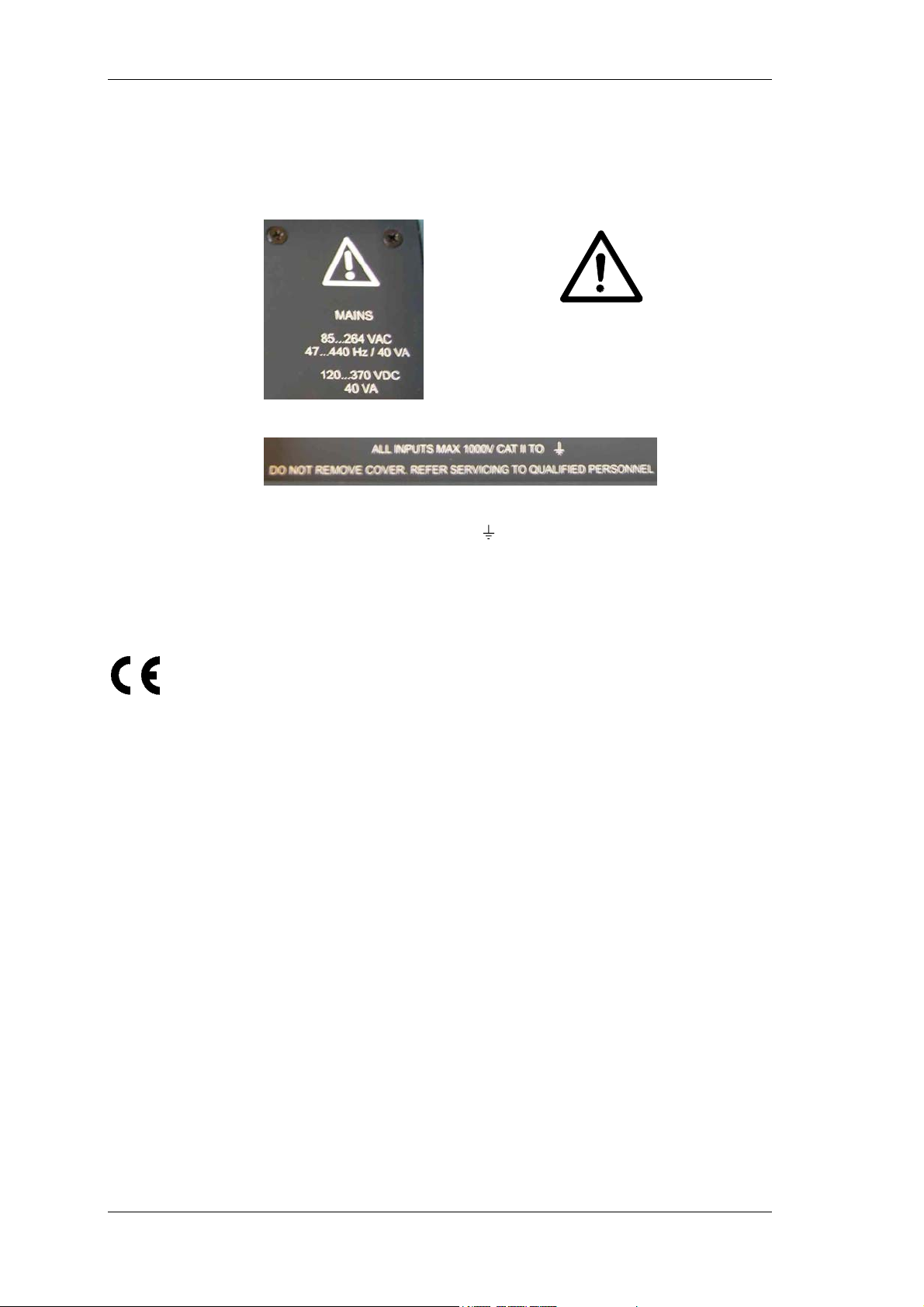
2.1 Safety instructions on the device housing
Mains connection
Input voltage and
maintenance
Indoor use only
The mains connection must conform to the following
ranges/values:
85...264 VAC, 47...440 Hz/ 40 VA
The maximum input voltage for over-voltage category CAT II may
not exceed 1000 V to earth (
Do not remove the cover.
Refer servicing to qualified personnel.
The device may only be used indoors.
Conformity mark re. EC Low Voltage Directive 73/23/EEC and
EMC Directive 89/336/EEC.
Mains:
120...370 VDC, 40 VA
).
6 Power Analyzer NORMA 4000, NORMA 5000
EO1111G REV G
Page 9
Design and functions
3 Design and functions
This chapter provides an overview of the terminals, ports and
interfaces of the power analyzer, as well as a list of display and
operating devices and a brief introduction to the basic functions of
the unit.
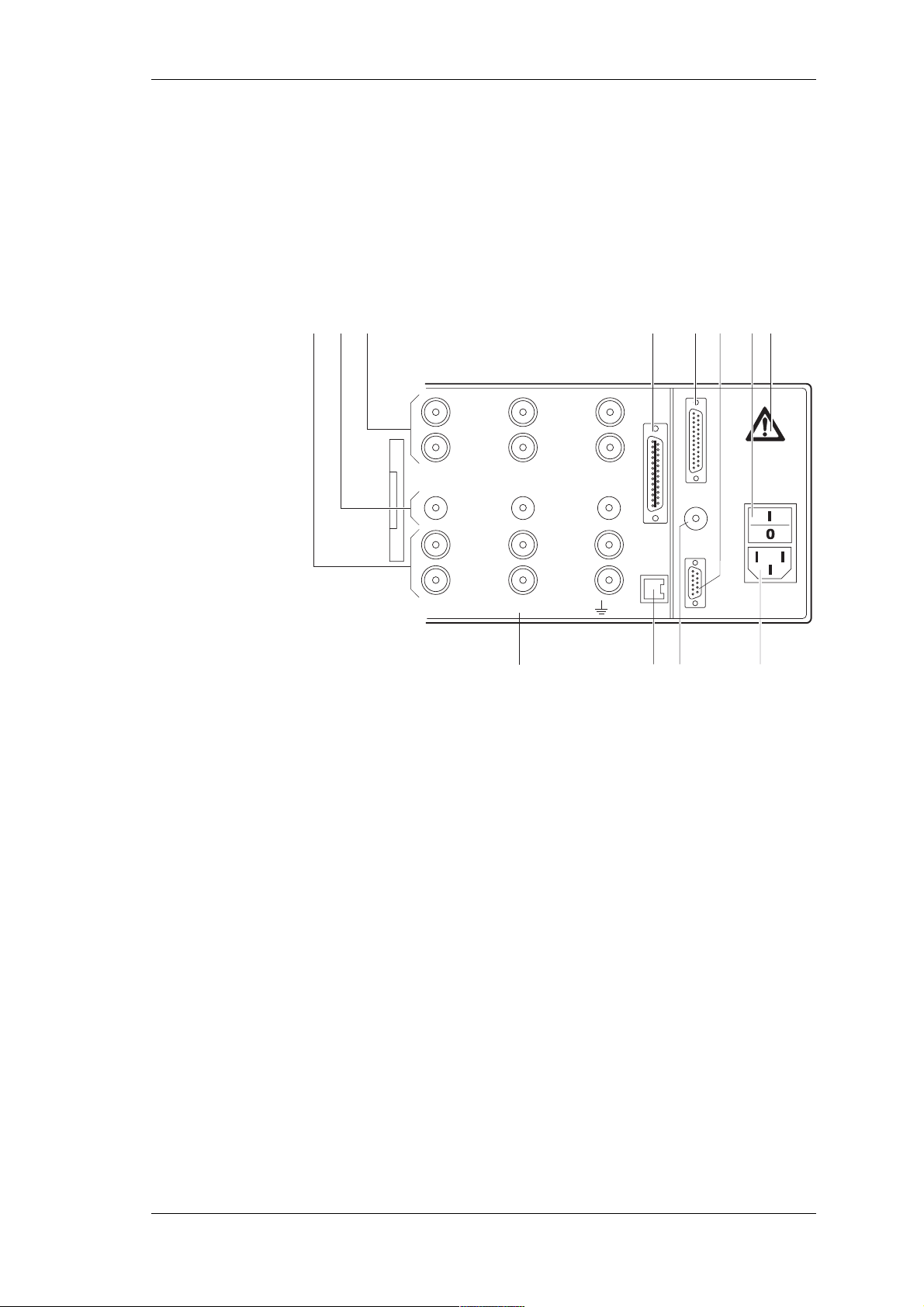
3.1 Terminals (rear of housing)
123
4 5 6 7
12
2
EXT.SHUNT
HI
VOLTAGE
1000 V max
LO
PROBE
10 V max
HI
CURRENT
10 A max
LO
1
HI
VOLTAGE
1000 V max
LO
3
PROBE
EXT.SHUNT
10 V max
HI
CURRENT
10 A max
LO
ALL INPUTS MAX 1000V CATII TO
11
1 Measuring inputs for current (channels 1 ... 6)
HI: Conductor, positive
LO: Conductor, negative
2 Measuring inputs for shunts (channels 1 ... 6)
3 Measuring inputs for voltage (channels 1 ... 6)
HI: Conductor, positive
LO: Conductor, negative
4 IEEE488 interface (optional)
5 Port for PI1 interface
6 Serial interface (RS 232)
7 Power switch
I: ON
0: OFF
8 Mains connection
9 Input for external synchronisation signal
10 IF2 network adapter (LAN) (optional)
11 Warning regarding max. voltage to earth
12 Warning symbol; danger, observe operating instructions
8910
Power Analyzer NORMA 4000, NORMA 5000 7
EO1111G REV G
Page 10
Design and functions
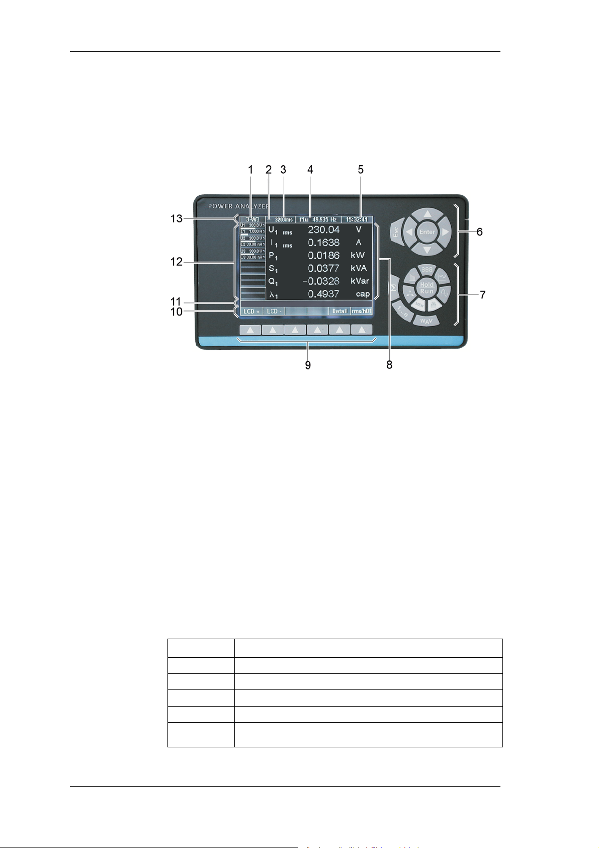
3.2 Operating controls and display
The display, operating controls and function keys are located at
the front of the device. The display consists of a menu bar, a
section in which the measured values and the channel settings are
shown and the assignment bar for the function keys.
1 Display of configuration;
menu item General Setup
2 Menu item Integration Setup / Motor-Generator Setup
3 Measurement status / display of average time
4 Display of synchronisation source frequency;
menu item Timing & Sync Setup
5 Display of time;
menu item Clock Setup
6 Navigation keys
7 Measuring keys
8 Display for measured values
9 Function keys
10 Assignment bar for function keys
11 Information row
12 Status display for channels 1 to 6 (including measuring
range, coupling and modulation bar);
menu items Current Channel Setup and Voltage
Channel Setup
13 Menu bar with menu items
Status Description
M
T
R
H
∫
Memory record active
Wait for Trigger start condition(memory)
Measurement active (Run mode)
Measurement stopped (Hold mode)
Integration of selected values active
8 Power Analyzer NORMA 4000, NORMA 5000
EO1111G REV G
Page 11
Design and functions
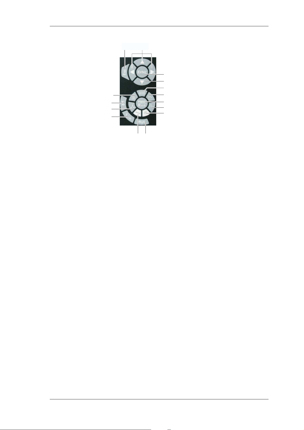
Navigation and
measuring keys
25
24
23
22
26 27
14
27
15
16
17
18
19
Navigation
through display
21 20
14 Enter: confirm; call up menu
15 Numerical display
16 Recorder
17 Hold/Run: start/stop measurement
18 Oscilloscope diagrams
19 Print
20 Show power, current, voltage
21 Save
22 Select channel
23 Vector display
24 Show totals of all channels
25 Frequency analysis
26 Esc: cancel, up one menu level
27 Cursor keys: up/down; left/right
Use the navigation keys (6, page 8) and (27) to navigate through
the display and the menus.
The active menu item, display or entry field in which your cursor is
located is backlit.
Press Esc (26) to cancel an entry without saving or to go to the
next higher menu level.
Press Enter (14) to call up a menu or to confirm an entry made in a
menu.
Press the measuring keys (7, page 8) and (15) to (25) to select the
display mode and the saving/output functions for measured values.
The assignment of the function keys (9, page 8) varies, depending
on the current menu. The current key assignment is shown on the
assignment bar (10, page 8) located above the function keys.
Power Analyzer NORMA 4000, NORMA 5000 9
EO1111G REV G
Page 12
Design and functions
Overview of
function keys
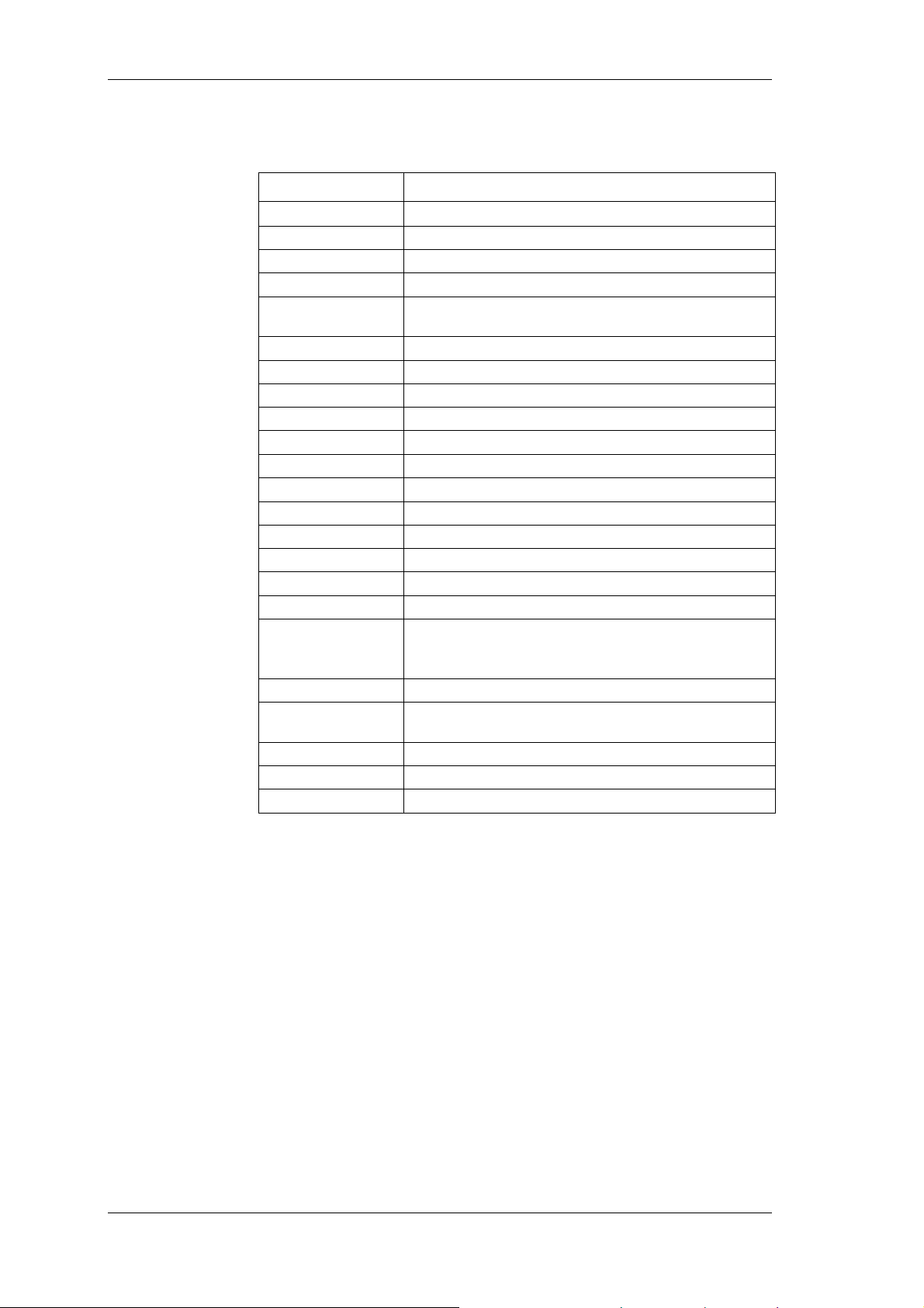
The assignment of the function keys varies, depending on the
display or menu you have selected.
Name Function
Default
DELETE
Detail
Freq
Info…
LCD LCD +
lin/log
LOAD
mode
Offset
rms/h01
SAVE
Scale
scroll
Set all
tab/gra
U/I
zoom
∫
∫ Clear
∫ Start
∫ Stop
Scale axes automatically
Delete configuration
View details of a measured value
Set frequency analysis filter
View system information and version number of
unit firmware
Reduce brightness of display
Increase brightness of display
View linear/logarithmic scale
Load configuration
View table with harmonics
Adjust zero (with cursor keys)
View rms values or H01 fundamental
Save configuration
Adjust scales of axes (with cursor keys)
Scroll through display
Adopt configuration or set value for all channels
View measured values in table/graph
Switch between voltage channel configuration
and current channel configuration (in General
Setup)
Adjust scales of axes (with cursor keys)
View electrical work reference power or
recuperated power
Set electrical work integration to zero
Start electrical work integration
Stop electrical work integration
3.3 Functions
The power analyzer allows for the analysis of currents from DC to
several MHz. Voltage values up to 1000 V and currents up to 20 A
are measured accurately, and the respective real, idle and
apparent power is calculated. The limit of error is between 0.1%
and 0.3%, depending on the model. For DC and AC up to a few
MHz, it is not affected by the wave shape, frequency or phase
position. The measuring range can be extended by connecting
shunts or clamps. When extending the range using third-party
shunts or clamp the extra errors due to these devices should be
considered. The device caters for simultaneous measuring in up to
6 channels.
10 Power Analyzer NORMA 4000, NORMA 5000
EO1111G REV G
Page 13
Startup
4 Startup
4.1 Checking of delivery
Before commencing work with the analyzer, check the delivery
to ensure that it is compete, using the following list and the
delivery specifications:
- 1 power analyzer
- 1 operating manual
- 1 mains cable
- 1 calibration certificate
- 1 to 6 voltage and current channel modules, according to
the delivery specifications
4.2 Installation and switching on
Installation
Fehler! AutoText-Eintrag nicht definiert.
Switching device
on
Follow the safety instructions regarding ambient conditions and
location of installation.
Danger! Risk of electrocution
Caution! The device is connected to the power mains, and a
number of internal components are live with dangerous voltage
levels. To remain safe during operation, the device must be
equipped with a low-resistance connection to the earth.
Therefore check the mains socket and its wiring!
Place the device onto a clean and stable surface.
If necessary adjust the feet at the base of the unit to improve
the view onto the display.
Connect the device to the mains socket, using the power lead.
Set the power switch at the rear of the housing to position "I".
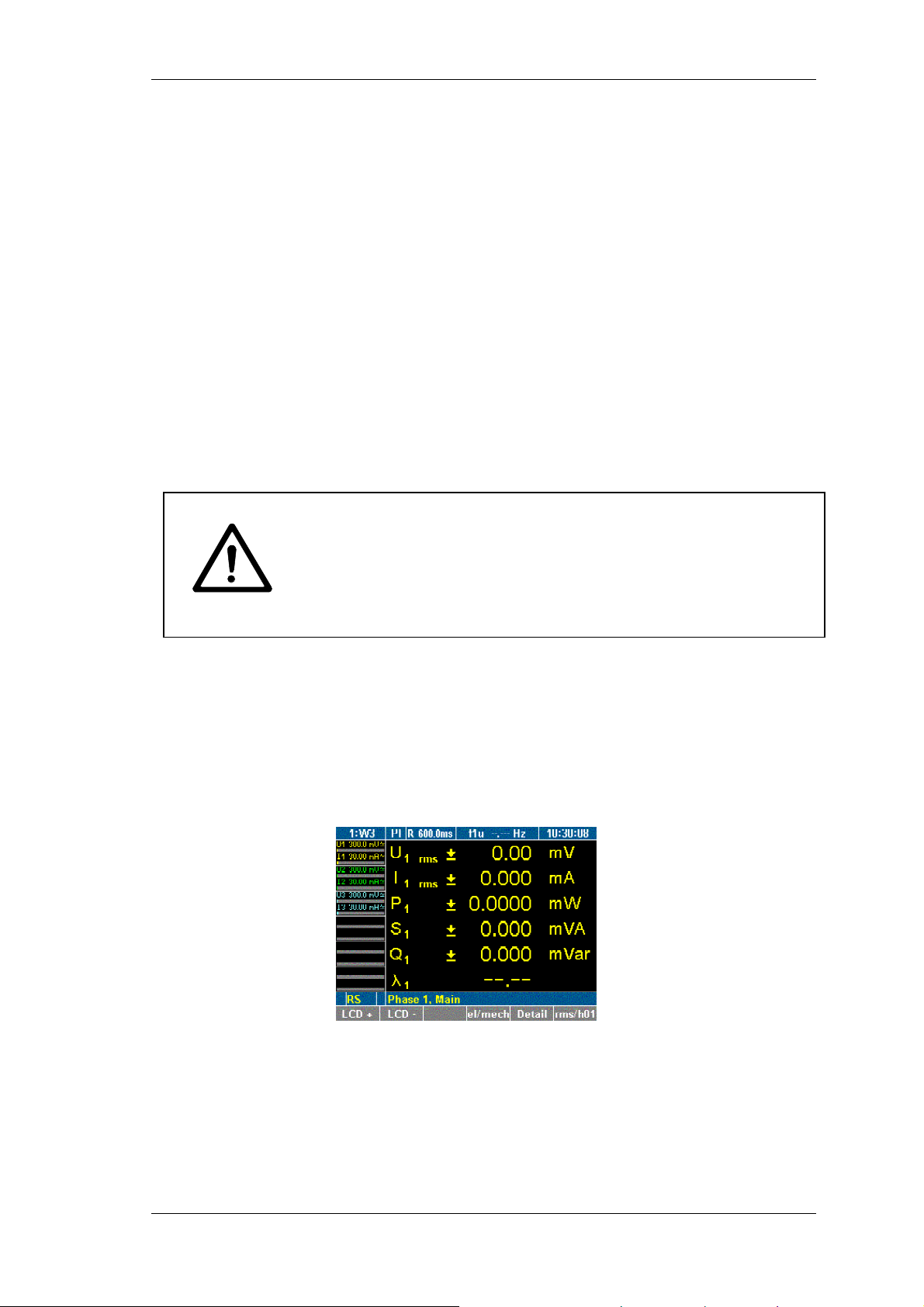
The device is now ready for operation. The start screen is
displayed.
Switching device
off
Power Analyzer NORMA 4000, NORMA 5000 11
EO1111G REV G
Set the power switch at the rear of the housing to position "0".
If the device is not to be used for a prolonged period of time,
disconnect the plug from the mains socket.
Page 14
Connection to Circuits
5 Connection to Circuits
Fehler! AutoText-Eintrag nicht definiert.
Danger! Risk of electrocution!
By connecting the unit to circuits, the terminals and certain
parts inside the device are live.
In order to ensure safe operation, first connect the device to the
power supply.
If possible, open the circuit before establishing a connection to
the analyzer.
Prior to connecting the circuits, ensure that the maximum
measuring voltage and max. voltage to earth (1000V CATII and
600V CATIII respectively) are not exceeded.
Do not use leads and accessories that do not fulfil the relevant
safety standards, as this could lead to serious injury or death
from electric shock!
5.1 Connecting sequence
When connecting a circuit to the power analyzer, for safety
reasons, proceed in the sequence outlined below:
1. Connect the power analyzer to the mains socket.
The analyzer is now connected to the protective earth wire.
2. Switch on the power analyzer.
3. Connect the measuring circuit as shown in the connection
diagram.
Ensure that the phase is connected to HI so that the energy
flow is from HI to LO; to ensure that the measured values are
indicated correctly.
4. Connect the circuit to the power supply.
5.2 Overview
The power analyzer offers the following options for connection:
Measurement direct with shunt with
transducer
1-phase
measurement
Aron connection
3-phase
measurement in 4wire system
Note
When connecting a 4-channel device for electrical efficiency
analysis, the 3-phase power cables for this measurement should be
connected to the measuring channels 1 to 3, so that the efficiency
can be calculated and displayed directly on the device.
12 Power Analyzer NORMA 4000, NORMA 5000
EO1111G REV G
page 13 page 14 page 15
page 16 page 17 page 18
page 19 page 20 -
Page 15
Connection to Circuits
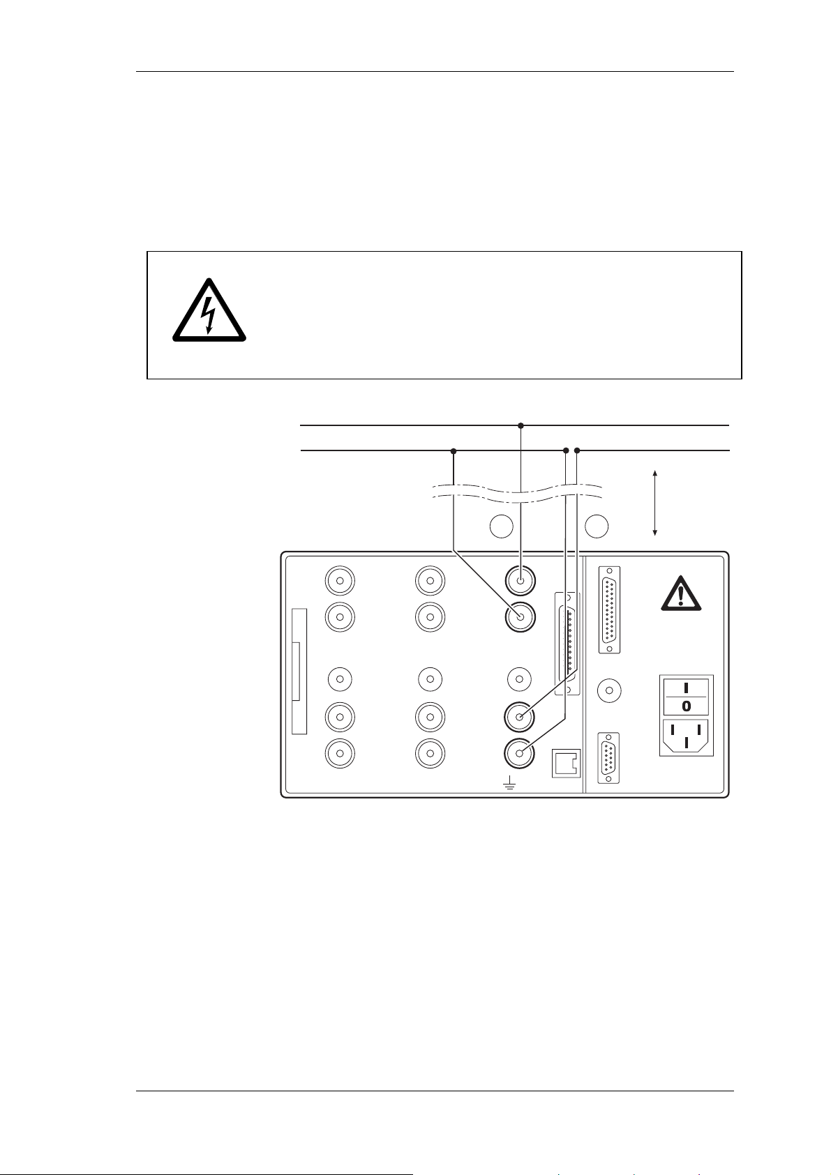
5.3 1-phase measurement
5.3.1 Direct connection
Ensure that there is no overload at the current input of the
power analyzer.
If necessary, install appropriate fuses.
Fehler! AutoText-Eintrag nicht definiert.
Danger! Risk of electrocution!
Risk of injury when touching connections, internal circuits and
measuring devices that are not earthed.
Always adhere to the instructions regarding the sequence of
connection (see page 12).
L1
N
max. 10 m
I
HI
VO LTAGE
1000 V max
LO
3
PROBE
EXT.SHUNT
10 V max
HI
CURRENT
10 A max
LO
ALL INPUTS MAX 1000V CATII TO
VO LTAGE
2
EXT.SHUNT
HI
1000 V max
LO
PROBE
10 V max
HI
CURRENT
10 A max
LO
U
1
Power Analyzer NORMA 4000, NORMA 5000 13
EO1111G REV G
Page 16
Connection to Circuits
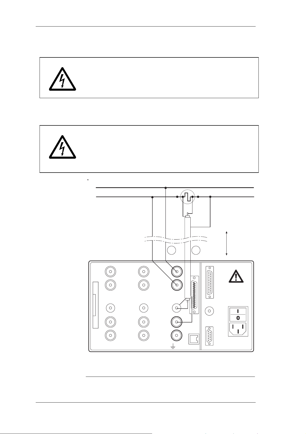
5.3.2 With shunt
Fehler! AutoText-Eintrag nicht definiert.
Danger! Risk of electrocution! Do not touch sense terminals!
The sense terminals at the shunts are powered with the same
voltage as the power connections.
Shunts are not isolated.
Never touch the sense terminals at the shunts.
The connecting leads to the shunts should be as short as
possible in order to prevent noise voltages.
Fehler! AutoText-Eintrag nicht definiert.
Danger! Risk of electrocution!
Risk of injury when touching connections, internal circuits and
measuring devices that are not earthed.
Always adhere to the instructions regarding the sequence of
connection (see page 12).
Last
L1
LOHI
N
Guard
*1
max. 10 m
I
U
HI
HI
VOLTAGE
VOLTAGE
1000 V max
1000 V max
LO
LO
1
2
3
PROBE
PROBE
EXT.SHUNT
EXT.SHUNT
10 V max
10 V max
HI
HI
CURRENT
CURRENT
10 A max
10 A max
LO
LO
ALL INPUTS MAX 1000V CATII TO
L1
N
Last
LO HI
Guard
*1
max. 10 m
I
VOLTAGE
2
EXT.SHUNT
HI
1000 V max
LO
PROBE
10 V max
HI
CURRENT
10 A max
LO
3
EXT.SHUNT
HI
VOLTAGE
1000 V max
LO
PROBE
10 V max
HI
CURRENT
10 A max
LO
ALL INPUTS MAX 1000V CATII TO
U
1
*1
We recommend using MCS measuring leads for triaxial shunts and MCP leads
for planar shunts. Triaxial shunts are equipped with guard connectors in the
plugs, while planar shuts are equipped with guard sockets.
14 Power Analyzer NORMA 4000, NORMA 5000
EO1111G REV G
Page 17
Connection to Circuits
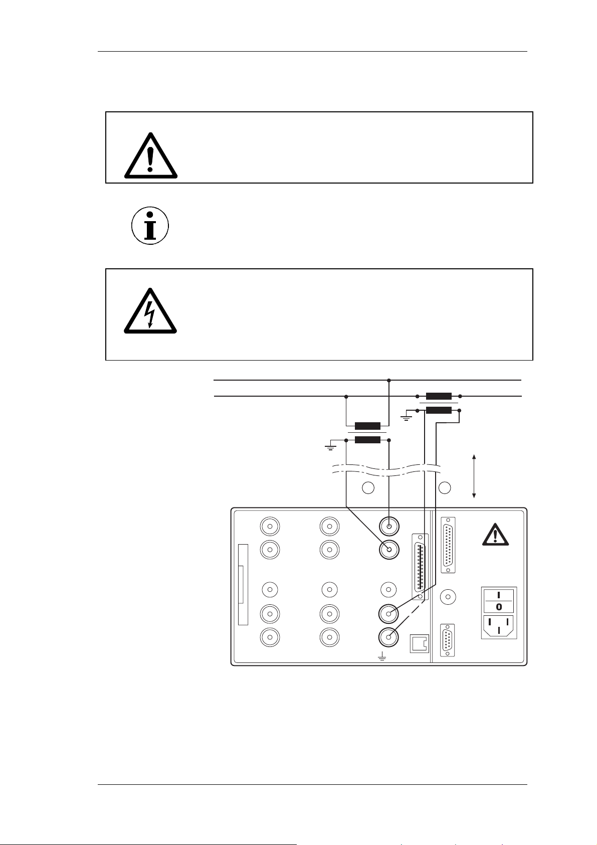
5.3.3 With voltage and current transducer
Fehler! AutoText-Eintrag nicht definiert.
Risk of damage to transducer, due to overload!
Check rating of transducer.
Note
When using transducers, please note that transducer errors limit
the measuring bandwidth and reduce the intrinsic uncertainty.
Fehler! AutoText-Eintrag nicht definiert.
Danger! Risk of electrocution!
Risk of injury when touching connections, internal circuits and
measuring devices that are not earthed.
Always adhere to the instructions regarding the sequence of
connection (see page 12).
L1
N
P
1
S
1
AN
P
2
S
2
an
max. 10 m
U I
2
EXT.SHUNT
HI
VOLTAGE
1000 V max
LO
PROBE
10 V max
HI
CURRENT
10 A max
LO
1
HI
VOLTAGE
1000 V max
LO
3
PROBE
EXT.SHUNT
10 V max
HI
CURRENT
10 A max
LO
ALL INPUTS MAX 1000V CATII TO
Power Analyzer NORMA 4000, NORMA 5000 15
EO1111G REV G
Page 18
Connection to Circuits
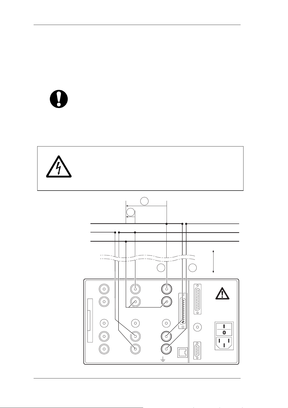
5.4 Aron circuit (triaxial/guard technique)
5.4.1 Direct connection
the Aron circuit is only available for 3-wire networks.
It is only required to measure two phases (currents I1 and I2 in the
connection diagram), as I1+I2+I3 must be 0.
Important
In most cases, the Aron circuit is not acceptable for measurements
on inverters, as there are capacitive leakage currents from the
windings to the housing!
Ensure that there is no overload at the current input of the
power analyzer.
If necessary, install appropriate fuses.
Fehler! AutoText-Eintrag nicht definiert.
Danger! Risk of electrocution!
Risk of injury when touching connections, internal circuits and
measuring devices that are not earthed.
Always adhere to the instructions regarding the sequence of
connection (see page 12).
U
13
L1
L2
L3
3
EXT.SHUNT
HI
VOLTAGE
1000 V max
LO
PROBE
10 V max
HI
CURRENT
10 A max
LO
U
23
2
HI
VOLTAGE
1000 V max
LO
PROBE
EXT.SHUNT
10 V max
HI
CURRENT
10 A max
LO
max. 10 m
I
2
I
1
1
ALL INPUTS MAX 1000V CATII TO
16 Power Analyzer NORMA 4000, NORMA 5000
EO1111G REV G
Page 19
Connection to Circuits
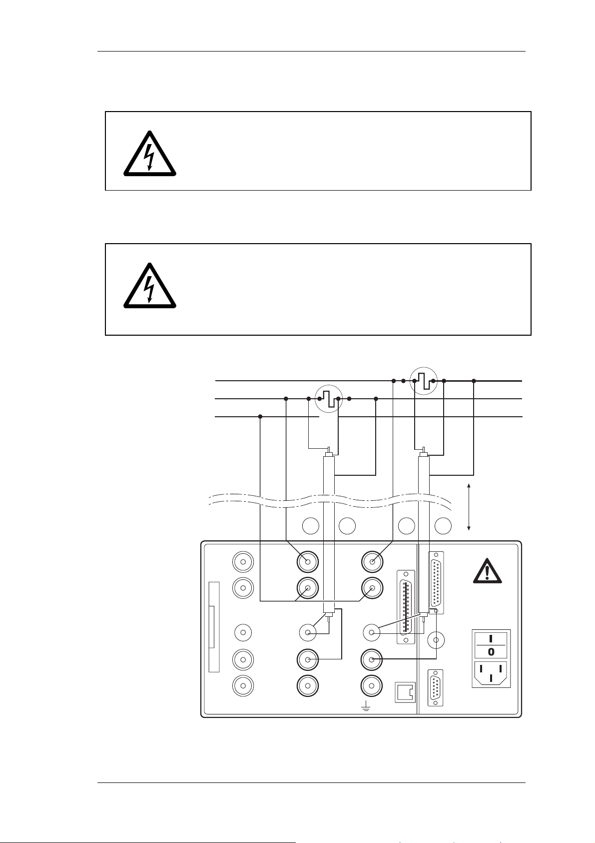
5.4.2 With shunt
Fehler! AutoText-Eintrag nicht definiert.
Danger! Risk of electrocution! Do not touch sense terminals!
The sense terminals at the shunts are powered with the same
voltage as the power connections.
Shunts are not isolated.
Never touch the sense terminals at the shunts.
The connecting leads to the shunts should be as short as
possible in order to prevent noise voltages.
Fehler! AutoText-Eintrag nicht definiert.
Danger! Risk of electrocution!
Risk of injury when touching connections, internal circuits and
measuring devices that are not earthed.
Always adhere to the instructions regarding the sequence of
connection (see page 12).
LO
Last
L1
L2
HI
HI
LO
L3
U
23
2
HI
VOLTAGE
1000 V max
LO
PROBE
EXT.SHUNT
10 V max
HI
CURRENT
10 A max
LO
HI
VOLTAGE
1000 V max
LO
3
PROBE
EXT.SHUNT
10 V max
HI
CURRENT
10 A max
LO
ALL INPUTS MAX 1000V CATII TO
Guard
*1
I
2
Guard
*1
max. 10 m
U
13
I
1
1
Power Analyzer NORMA 4000, NORMA 5000 17
EO1111G REV G
Page 20
Connection to Circuits
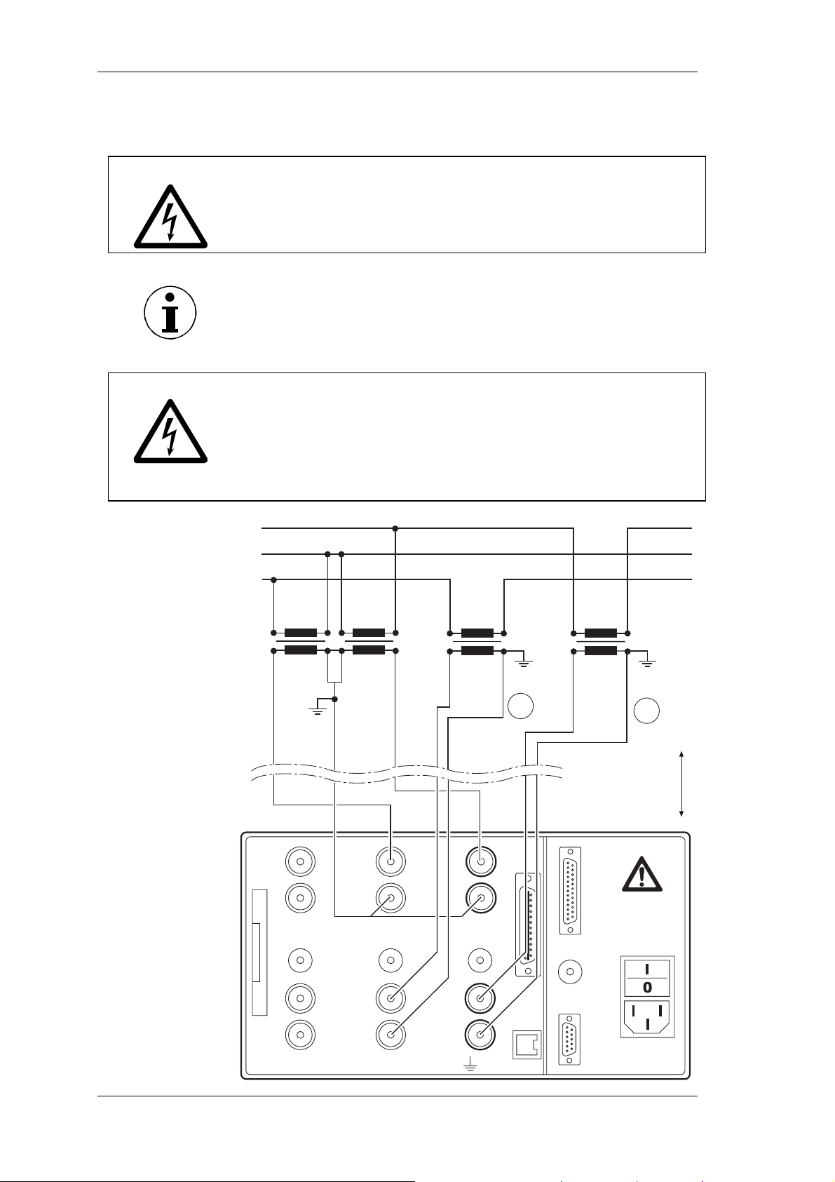
5.4.3 With voltage and current transducer
Fehler! AutoText-Eintrag nicht definiert.
Risk of damage to transducer due to overload!
Check rating of transducer.
Note
When using transducers, please note that transducer errors limit
the measuring bandwidth and reduce the intrinsic uncertainty.
Fehler! AutoText-Eintrag nicht definiert.
Danger! Risk of electrocution!
Risk of injury when touching connections, internal circuits and
measuring devices that are not earthed.
Always adhere to the instructions regarding the sequence of
connection (see page 12).
L1
L2
L3
CBA
HI
VOLTAGE
1000 V max
LO
3
PROBE
EXT.SHUNT
10 V max
abc
VOLTAGE
2
EXT.SHUNT
P1
L3
S1
L3
HI
1000 V max
LO
PROBE
10 V max
P2
S2
P1
L1
L3
S1
L1
L3
I
3
P2
S2
L1
L1
I
1
max. 10 m
1
HI
CURRENT
10 A max
LO
ALL INPUTS MAX 1000V CATII TO
HI
CURRENT
10 A max
LO
18 Power Analyzer NORMA 4000, NORMA 5000
EO1111G REV G
Page 21
Connection to Circuits
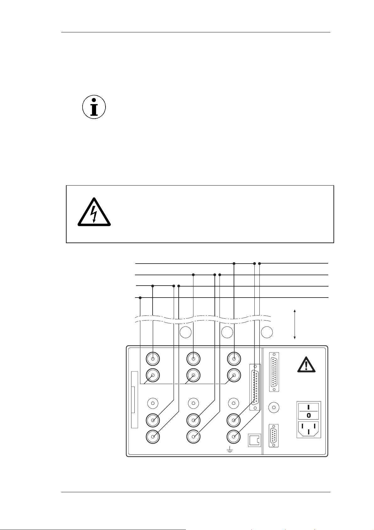
5.5 3-phase measurement in 4-wire system
5.5.1 Direct connection
Note
3-phase measurements in 3-wire systems are only possible via a
star point adapter (creates neutral point) plugged into the voltage
inputs.
Ensure that there is no overload at the current input of the
power analyzer.
If there is a potential risk of overload at the current input,
incorporate a shunt or transducer into the circuit.
If necessary, install appropriate fuses.
Fehler! AutoText-Eintrag nicht definiert.
Danger! Risk of electrocution!
Risk of injury when touching connections, internal circuits and
measuring devices that are not earthed.
Always adhere to the instructions regarding the sequence of
connection (see page 12).
L1
L2
L3
N
I
3
2
HI
VOLTAGE
1000 V max
LO
PROBE
EXT.SHUNT
10 V max
HI
CURRENT
10 A max
LO
HI
VOLTAGE
1000 V max
LO
3
PROBE
EXT.SHUNT
10 V max
HI
CURRENT
10 A max
LO
ALL INPUTS MAX 1000V CATII TO
max. 10 m
I
2
I
1
1
Power Analyzer NORMA 4000, NORMA 5000 19
EO1111G REV G
Page 22
Connection to Circuits
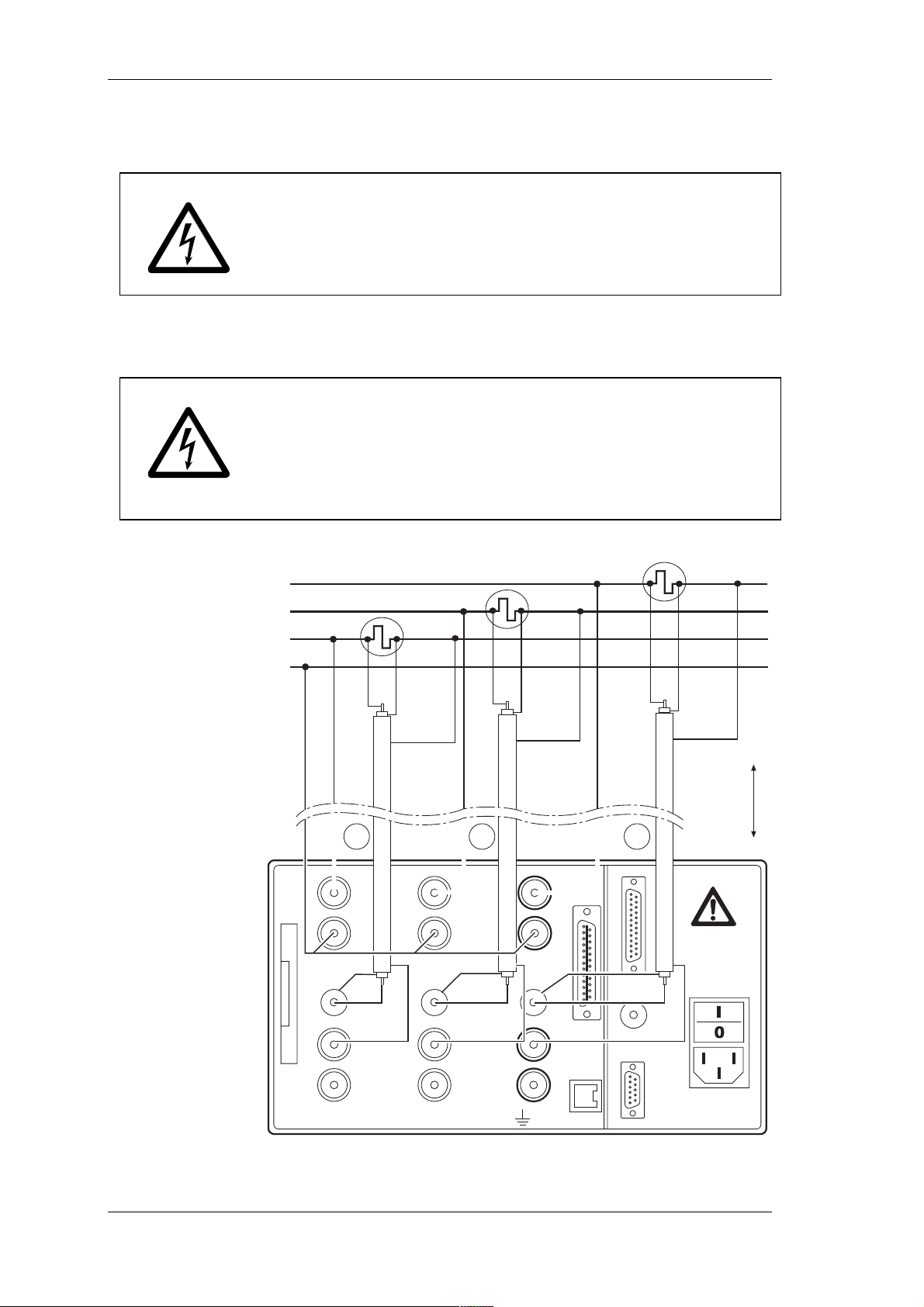
5.5.2 With shunt
Fehler! AutoText-Eintrag nicht definiert.
Danger! Risk of electrocution! Do not touch sense terminals!
The sense terminals at the shunts are powered with the same
voltage as the power connections.
Shunts are not isolated.
Never touch the sense terminals at the shunts.
The connecting leads to the shunts should be as short as
possible in order to prevent noise voltages.
Fehler! AutoText-Eintrag nicht definiert.
Danger! Risk of electrocution!
Risk of injury when touching connections, internal circuits and
measuring devices that are not earthed.
Always adhere to the instructions regarding the sequence of
connection (see page 12).
L1
L2
L3
N
HI LO
Guard
HI LO
*1
Guard
*1
HI LO
Guard
Last
*1
max. 10 m
I
3
HI
HI
VOLTAGE
VOLTAGE
1000 V max
1000 V max
LO
LO
3
3
PROBE
PROBE
EXT.SHUNT
EXT.SHUNT
10 V max
10 V max
HI
HI
CURRENT
CURRENT
10 A max
10 A max
LO
LO
ALL INPUTS MAX 1000V CATII TO
2
2
I
HI
HI
VOLTAGE
VOLTAGE
1000 V max
1000 V max
LO
LO
PROBE
PROBE
EXT.SHUNT
EXT.SHUNT
10 V max
10 V max
HI
HI
CURRENT
CURRENT
10 A max
10 A max
LO
LO
2
1
1
I
1
20 Power Analyzer NORMA 4000, NORMA 5000
EO1111G REV G
Page 23
Simple Measurement
6 Simple Measurement
This chapter contains an introduction to the measuring procedures
that can be carried out with the power analyzer, based on a simple
sample measurement. The example used here is a measurement
at the frequency converter with a fundamental below 100 Hz.
Connection to
circuits
Configuration
Connect the outputs of the frequency converter to the current
and voltage channels of the power analyzer (see chapter 5.5.1
“Direct connection”, page 19).
Switch on the power analyzer.
Measuring
Ensure that factory configuration 1:W3 is loaded (see chapter
7.2: "Load configuration", page 23).
The settings of factory configuration 1:W3 are as follows:
- Low-pass filter on, set to 100 Hz
- Average time set to approx. 300 ms, depending on the
measured frequency
- Synchronisation source is U1.
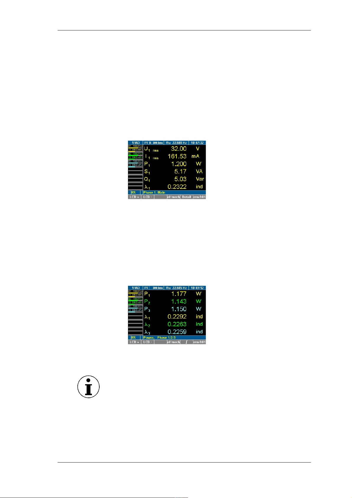
Press measuring key WAV three times.
The rms values for power in channels 1 ... 3 are displayed.
The numbers in subscript (e.g. U
channel.
or U2) indicate the respective
1
Note
As the power analyzer requires a complete voltage and current
cycle for an accurate measurement, a full period is automatically
added to the average time of 300 ms of configuration 1:W3, and the
new average time is displayed. Example: 309.9 ms at 22.585 Hz,
corresponding to 7 periods.
Power Analyzer NORMA 4000, NORMA 5000 21
EO1111G REV G
Page 24
Configuration
7 Configuration
Prior to measuring, you must configure the default settings, adjust
channels, measuring ranges and times and synchronise current
and voltage sources.
If you wish to reapply certain settings at a later stage, you must
save the configuration. You have the option to save up to 15 userdefined configurations, which are automatically assigned the
names 10:USER to 24:USER.
Configuration
1:W3
You may ...
When first switching on the analyzer, factory configuration 1:W3 is
used. This configuration is suitable for measurements with
fundamentals below 100 Hz (average time 300 ms,
synchronisation source U1, low-pass filter 100 Hz).
Note
You have the option to modify the settings of configuration 1:W3. If
you wish to save the new settings, you must do this in a new
configuration. Default configuration 1:W3 cannot be overwritten.
You may save new settings in the process or at the end of the
configuration procedure. Settings that have not been saved are lost
when the device is switched off or when a different configuration is
loaded.
- modify configuration 1:W3 loaded upon startup of the
device,
- load an existing configuration,
- create a new configuration,
- delete or modify an existing configuration.
The power analyser features the following configuration menus:
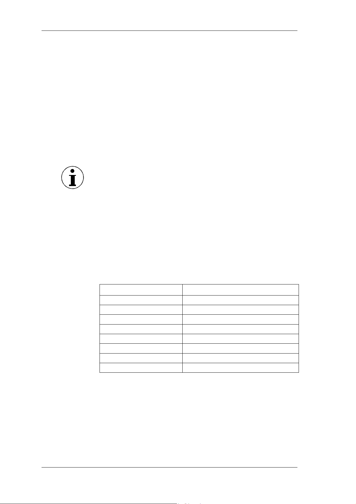
Configuration menu Description
General Setup
Timing & Sync Setup
Clock Setup
Current Channel Setup
Voltage Channel Setup
Motor / Generator Setup
Analog Output Setup
Integration Setup
Interfaces, printer output
Average time and synchronisation
Date and time
Current channels 1 … 6
Voltage channels 1 … 6
PI1 process interface inputs
PI1 process interface outputs
Integration function / energy
5 steps
To set up a configuration, complete the following steps:
- Call up General Setup
- Configure current and voltage channels
- Configure average time and synchronisationConfigure data
transfer to printer and PCSave configuration
For instructions on how to configure the PI1 process interface,
please refer to chapter 9: "PI1 Process Interface (optional)", page
57
For instructions on how to delete a configuration, please refer to
chapter 7.10 ”Delete configuration", page 37.
22 Power Analyzer NORMA 4000, NORMA 5000
EO1111G REV G
Page 25
Configuration
7.1 Call up General Setup / Call up system
information screen
Call up General
Setup
Call up system
information
screen
Analyzer is switched on; start screen is displayed.
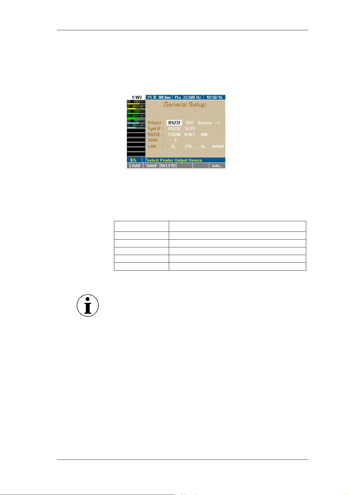
Move the cursor to menu item General Setup that shows the
name of the currently loaded configuration and press Enter.
The General Setup menu is displayed.
General Setup menu is displayed.
Press function key F6 Info.
The System Info menu is displayed.
This screen shows the main information about the unit.
Line Description
System
Phases
Options
Serial
Version
Devices type and sample rate
Type and number of equipped power phases
Equipped interfaces and options
Serial number
Firmware version
7.2 Load configuration
Note
If you have not set up and saved a new configuration before, you
are currently working with factory configuration 1:W3.
Proceed as described in chapter 7.3: "Configure data transfer to
printer and PC" 23.
Load
configuration
(optional)
Press function key LOAD.
A list showing all existing configurations is displayed.
Select a configuration and confirm with Enter.
The name of the loaded configuration, e.g. 10:USER, is
displayed in menu item General Setup.
To modify the loaded configuration, proceed as described below.
7.3 Configure data transfer to printer and PC
If you wish to use an internal or external printer, of if you intend to
connect a PC, you must configure the parameters for the data
exchange. This procedure consists of the following steps:
- Configure external printer
- Configure interface to PC
- Configure RS 232
- Configure IEEE488 device address
- Configure LAN network addresses
Power Analyzer NORMA 4000, NORMA 5000 23
EO1111G REV G
Page 26
Configuration
Note
The actual selected Interface is displayed in the Information row
(see Chapter 3.2). RS Æ RS232 , GP Æ IEEE488, EN Æ Ethernet,
US Æ USB
In the General Setup menu, define the following settings:
Line Function
Printer
Syst IF
RS232
GPIB
LAN
Configure printer
Configure interface to PC
Configure RS232 interface
Configure IEEE488 device address
Configure network addresses
The device can be equipped with an IEEE 488 and/or an Ethernet
interface instead of a serial RS232 interface.
Configure
external printer
Settings Description
RS232
intern
On key
Off
Screen
Num
1/page
3/page
PCL
EPS 9p
EPS 24p
S/W
Print via RS232 interface on external printer or
use internal printer
Printer activated
Printer deactivated
Print screenshot
Print numerical data
Print 1 screenshot per page
Print 3 screenshots per page
PCL printer
Epson 9-pin printer
Epson 24-pin printer
Printing color is black/white
Note
The PCL setting is suitable for most inkjet printers.
Move the cursor to the field with the value you wish to change,
enter the new value and confirm with ENTER.
Select the settings and confirm with Enter.
The applied settings are shown in line Printer.
Configure
interface to PC
Settings Description
RS232
GPIB
USB
LAN
SCPI
D5255S
D5255T
D5255M
Serial interface
IEEE488 interface (optional)
USB2.0 interface (optional)
Ethernet (LAN) interface (optional)
Standard set of commands
Previous set of commands (emulation)
Previous set of commands (emulation)
Previous set of commands (emulation)
24 Power Analyzer NORMA 4000, NORMA 5000
EO1111G REV G
Page 27
Configuration
Move the cursor to the field with the value you wish to change,
enter the new value and confirm with ENTER.
Select the settings and confirm with Enter.
The applied settings are shown in line Syst IF.
Note
A driver CD to install USB support to the PC is included in the
delivery content. USB interface is installed as a virtual COM port.
Configure RS 232
Settings Description
115200 ...1200
8/N/1 …7/O/1
none
Baud rate of serial interface
Data bits/parity/stop bits of the serial interface
Handshake (protocol) of the serial interface
HW
XON
Note
The factory settings of the RS232 interface are optimised for
communication with a PC. We recommend adjusting the settings of
the PC to suit these parameters.
Factory configuration: 115200 8/N/1 HW
At the connected PC, call up the Device Manager and open the
dialog showing the settings for the serial port.
Adjust these settings to those of the power analyzer.
Note
If the cable connecting the two devices is extremely long, or if the
PC is unable to handle data at the set rate, you might consider
adjusting the settings for the RS232 at the power analyzer to those
of the PC. To do this, proceed as follows:
Move the cursor to the first field in line RS232.
Enter the settings for baud rate, data bits/parity/stop bits and
handshake and confirm with Enter.
The new settings are now shown in the fields of line RS232.
Save the settings with SAVE in the desired configuration.
Configure GPIB
address
The GPIB port is an IEEE488 interface. It works like an IP address
in a network. The power analyzer is assigned a unique device
address (numerical code) for communication on the GPIB bus. If
more than one device is used simultaneously in the network, the
device address can be adjusted accordingly.
Move the cursor to the field in line GPIB and press Enter.
A list with available addresses is displayed.
Select an address that has not yet been assigned at the GPIB
bus and confirm with Enter.
The selected address is shown in line GPIB.
Power Analyzer NORMA 4000, NORMA 5000 25
EO1111G REV G
Page 28
Configuration
Configure
Ethernet
Settings Description
0.....
0.....
0….
Telnet
Device IP address
IP subnet mask address
IP gateway address
Protocol (fixed)
Before the Ethernet interface can be operated properly, enter the
correct network addresses.
Move the cursor to the field in line LAN and press Enter.
A window with a numerical entry field is displayed.
Enter the required address and confirm with Enter.
The address is shown in line LAN.
Save the settings with SAVE in the desired configuration.
Press ESC to leave the entry field without changing the address.
Note
The default address is 0.0.0.0 (factory settings). Addresses can
only be entered in conjunction with IP network addressing (e.g.
address 193.0.255.4).
Important
Network addresses are available from your network administrator.
Call up Timing &
Sync Setup
7.4 Configure average time and synchronisation
This configuration concerns important parameters required for the
synchronisation of the measuring procedure. To configure these
parameters, proceed as follows:
- Call up Timing & Sync Setup
- Enter average time
- Select synchronisation source
- Set trigger level
- Select slope direction
- Select low-pass filter
- Configure signal output
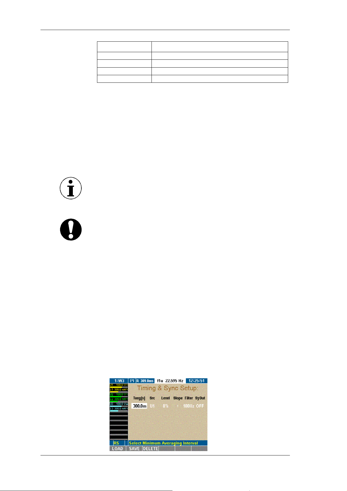
Move the cursor to menu item Timing & Sync Setup and press
Enter.
The Timing & Sync Setup menu is displayed. The value in
column Tavg[s] is highlighted.
26 Power Analyzer NORMA 4000, NORMA 5000
EO1111G REV G
Page 29
Configuration
In the Timing & Sync Setup menu, define the following settings:
Column Settings Description
Tavg[s] 15 ms... 3600 s
Minimum average time (in
seconds)
Src U1 / I1 … U6 / I6
ext
Off
Level −150 % ... +150 %
Synchronisation source
Fixed average time
Trigger level
(in % of measuring range)
Slope
↑
oder
↓
Filter 10 kHz
1k Hz
Slope direction
Synchronisation filter
(filter is not in signal path)
100 Hz
off
SyOut On
Off
Signal output enabled
Signal output disabled
(at Sync Ext output)
Set average time
The average time is a multiple of the period of the voltage of
current source. The settings are automatically adjusted during
measuring. Example: the average time is set to 19 ms; at a
frequency of 50 Hz, it is automatically adjusted to 1 period, i.e.
20 ms.
Note
Short average times are useful, if you wish to analyse individual
periods, measuring even minute interferences. With long average
times (e.g. 300 ms at 50 Hz), short-term interferences are not
shown.
Value in column Tavg[s] is highlighted.
Press Enter.
A window with a numerical entry field is displayed.
Enter the first digit of the average time and confirm with Enter.
Repeat the above step for the other digits.
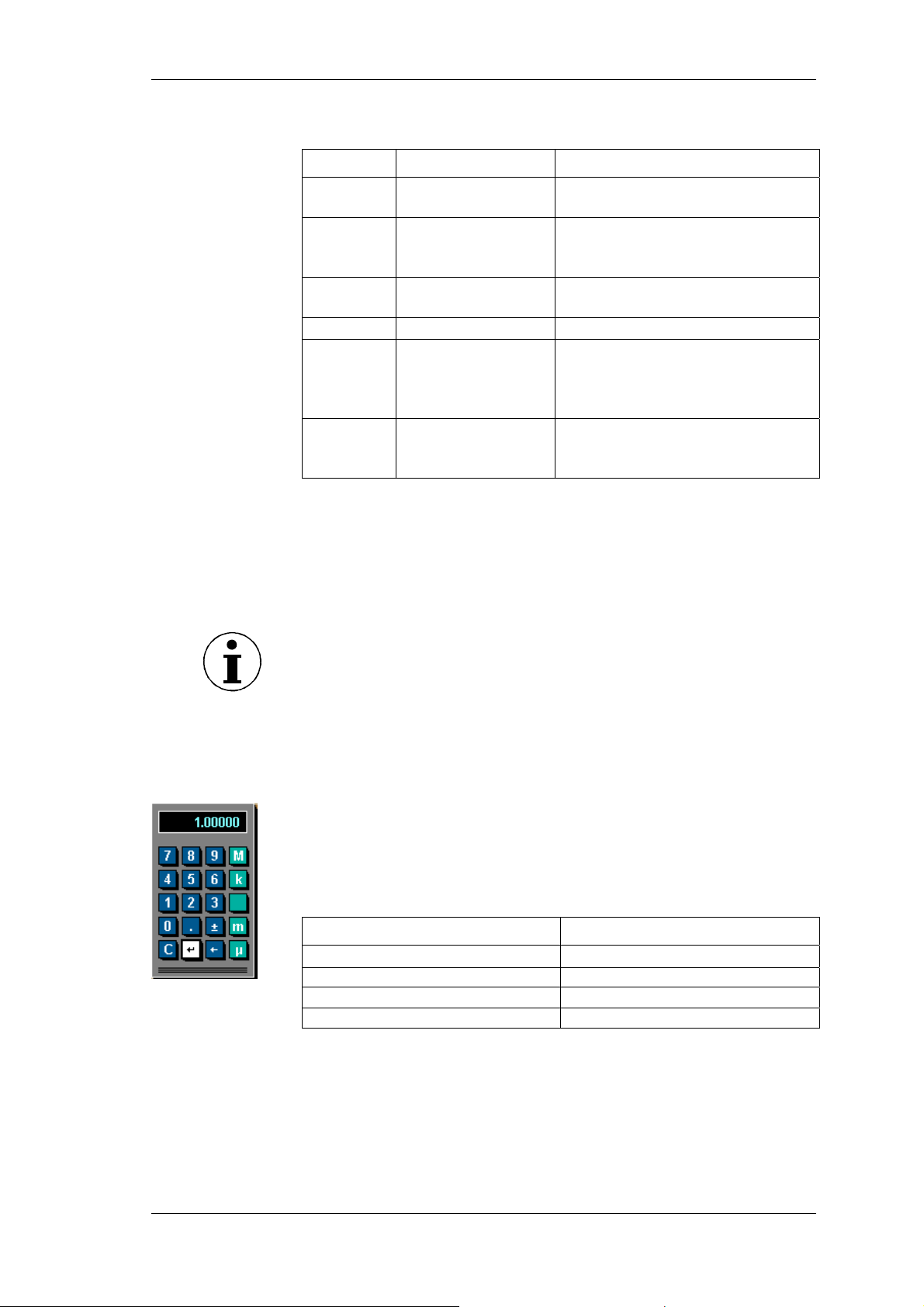
The measuring time is entered in seconds. For exponential
powers, use the following keys on the numerical keypad:
Exponential power Key
micro [10–6]
milli [10–3] m
µ
kilo [103] k
mega [106] M
Enter the exponential power and confirm with Enter.
Move the cursor to the return field of the calculator and press
Enter.
The average time is shown in column Tavg[s].
Save the settings with SAVE in the desired configuration.
Power Analyzer NORMA 4000, NORMA 5000 27
EO1111G REV G
Page 30
Configuration
w
Select
synchronisation
source
Set trigger level
Select slope
direction
Select lo
-pass
filter
The synchronisation source determines the frequency on which
the analysis is based. In factory configuration 1:W3, the
synchronisation source is U1, as this signal tends to be reliable in
most cases.
The following options are available:
- Input at device (channel 1 ... 6), current or voltage
respectively (U1 ... U6, I1 ... I6)
- Ext for external synchronisation signal (connection to port
for external synchronisation signal)
- OFF, if no synchronisation source is used (e.g. measuring
+
of direct current)
Note
To measure the start-up of a machine, you might opt for an external
synchronisation signal (0,2Hz to sample rate, max. 50V), as there is
otherwise no signal at the beginning of the measuring procedure,
and thus no measured values.
Value in column Src is highlighted.
Press Enter.
Select a source or OFF and confirm with Enter.
The selected source or OFF is shown in column Src.
Save the settings with SAVE in the desired configuration.
The trigger level is in percentages of the measuring range, and
measured from the end value of the range. In factory configuration
1:W3, the trigger level is set to 0%.
Note
By increasing the trigger level, the level of the average is also
increased. In other words: if there are several positive slopes in the
zero crossing, a higher modulated signal can be triggered.
Value in column Level is highlighted.
Press Enter.
Enter the desired power and confirm with Enter.
The value is displayed in column Level.
Save the settings with SAVE in the desired configuration.
The value entered here determines the zero crossing at which the
measurement begins, i.e. zero crossing with positive or with
negative slope. In factory configuration 1:W3, a positive slope is
↑
set. The arrow symbol "
" indicates to a positive slope; symbol "↓"
indicates a negative slope.
Value in column Slope is highlighted.
Press Enter.
Select the desired arrow symbol and confirm with Enter.
The selected arrow symbol is shown in column Slope.
Save the settings with SAVE in the desired configuration.
The low-pass filter enables you to modify signals with high
harmonic content (e.g. PWM) so that they are synchronised to the
resulting fundamental. This ensures that all measured values refer
28 Power Analyzer NORMA 4000, NORMA 5000
EO1111G REV G
Page 31
Configuration
to this fundamental. The low-pass filter is not located in the signal
path so that the input signal is not in any way interfered with.
Value in column Filter is highlighted.
Press Enter.
Select a value or OFF, depending on the expected
fundamental, and confirm with Enter.
The entered value, or OFF, is shown in column Filter.
Save the settings with SAVE in the desired configuration.
Configure signal
output
Value in column SyOut is highlighted.
Press Enter.
To activate output, select ON.
– or –
To deactivate output, select OFF.
Confirm with Enter.
The entered value is shown in column SyOut.
Save the settings with SAVE in the desired configuration.
Note
The synchronisation output is connected at the Sync-BNC plug on
the backside of the unit. The output signal is a TTL pulse with 5Volt.
Important
The BNC can be used either as input or output. As soon as the
BNC plug is switched to input (EXT sync source or OFF selected)
the sync output menu is automatically switched to OFF (disabled).
Adjust date and
time
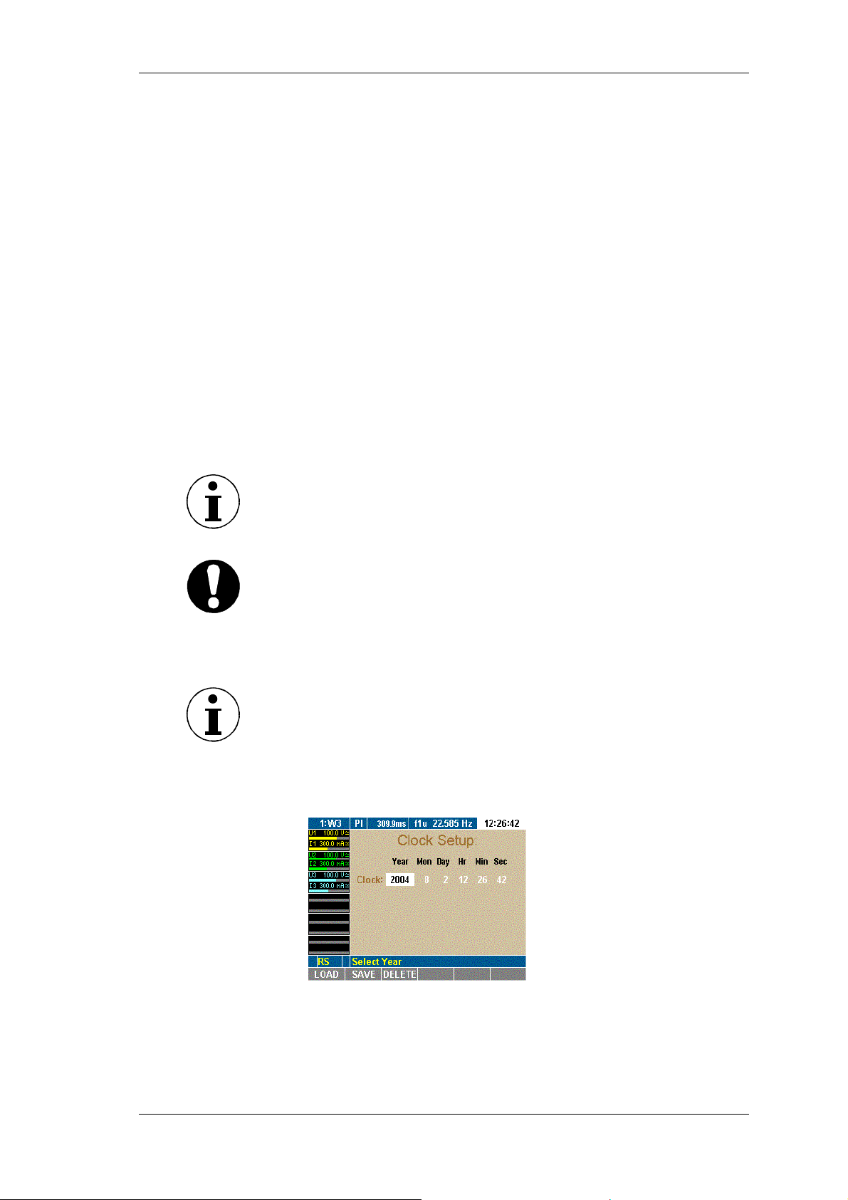
7.5 Adjust date and time
Note
Normally, date and time must be set only once, as they do not
change with different configurations.
Move the cursor to menu item Clock Setup and press Enter.
The Clock Setup menu is displayed. The value in column Year
is highlighted.
Press Enter, select a year and confirm with Enter.
The selected year is displayed.
Move the cursor to the next field and repeat the above step
until the correct date and time are shown.
Menu field Clock Setup shows the time in hours, minutes and
seconds.
Power Analyzer NORMA 4000, NORMA 5000 29
EO1111G REV G
Page 32
Configuration
7.6 Configure current and voltage channels
Prior to each measurement, you must configure the device inputs
(channels) to be used. The following example explains the
configuration procedure for current channel I1: The other current
and voltage channels can be configured in the same way.
The configuration procedure consists of the following steps:
- Call up Current Channel Setup
- Configure input range
- Configure scale
- Configure coupling
- Configure anti-aliasing filter
- Call up Voltage Channel Setup
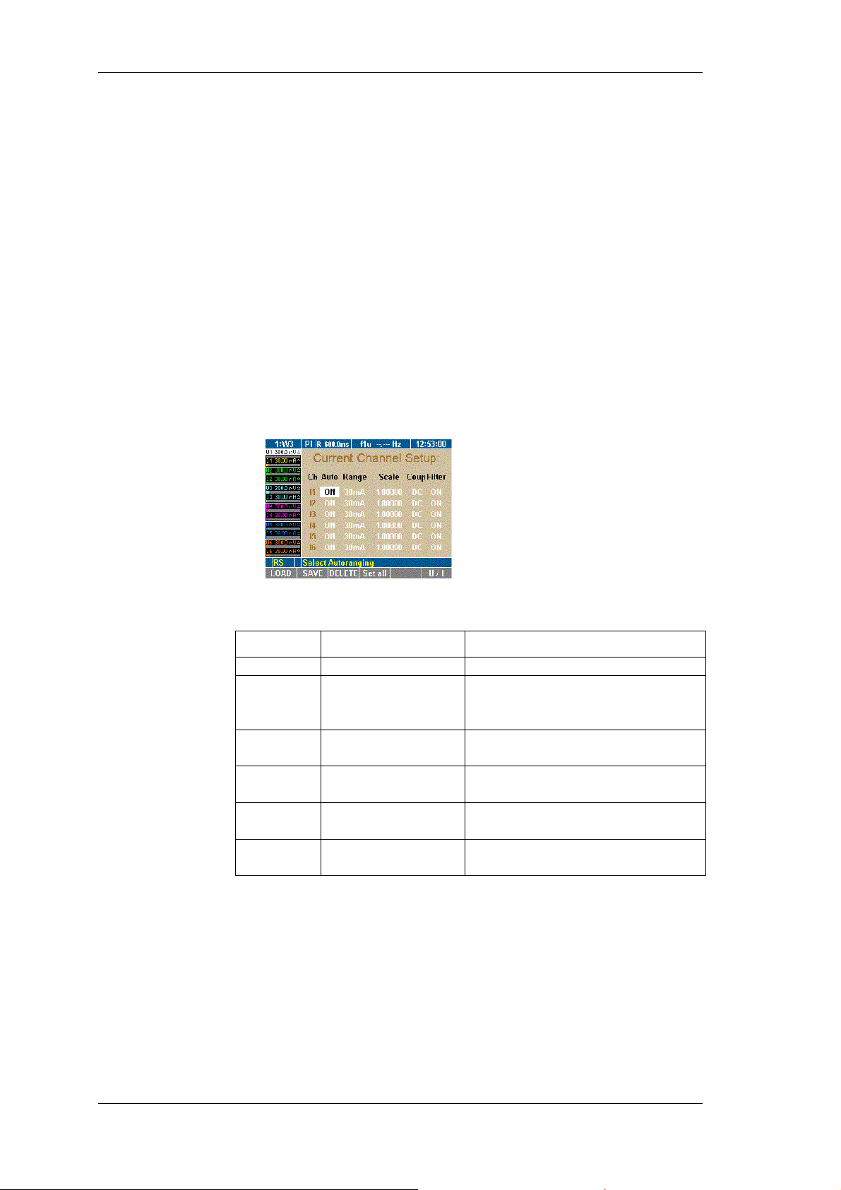
Call up Current
Channel Setup
Move the cursor to the status display of current channel I1 and
press Enter.
The Current Channel Setup menu is displayed. The first field in
column Auto of line I1 is highlighted.
Configure input
range
Automatic range
adjustment (Auto)
In the Current Channel Setup menu, define the following settings:
Column Settings Description
Ch I1 … I6
Auto
ON
OFF
Range 30 mA ...10 A
30 mV ... 10 V
Scale
Scale factor and
A/V ratio
Coup AC
Select input (channel)
Automatic range adjustment
activated
... deactivated
Measuring range (in ampere or
volt)
Scale for external
probes/converters
Coupling
DC
Filter ON
OFF
Filter activated
... deactivated
You have the option to select automatic range configuration for the
connected current source (Auto). Alternatively, you can configure
the range manually (Range).
With automatic configuration, the analyzer determines and
selected the correct range for the connected current source.
First field in column Auto is highlighted.
Press Enter.
Select ON and confirm with Enter.
The selected settings are shown in column Auto.
30 Power Analyzer NORMA 4000, NORMA 5000
EO1111G REV G
Page 33
Configuration
If you wish to configure all three current channels in this way,
press Set All.
All channels are now set to ON.
Save the settings with SAVE in the desired configuration.
Manual range
adjustment
(Range)
To manually configure the range for I1, enter the range in ampere
or, if e.g. shunts are used, in volt.
First field in column Auto is highlighted.
Press Enter, select OFF and confirm with Enter.
Automatic range adjustment is now disabled.
Move the cursor to the value in column Range and press
Enter.
Select a value in ampere,
– or –
if you use a shunt, select a value in volt.
Note
When a value in volt is entered, automatic configuration (Auto) is
set to Off. Below Scale, option menu A/V is displayed.
Confirm with Enter.
The settings are shown in column Range. Off is displayed in
column Auto.
If you wish to configure all three current channels in this way,
press Set All.
Save the settings with SAVE in the desired configuration.
Configure scale
If you intend to use a shunt or a probe, you must adjust the scale
for the output of the measuring signal.
Note
The correct parameter settings are shown on the type plate of the
shunt or probe.
You can ...
- enter the transducer ratio (U over I) at the external current
meters and instruct the device to calculate the final scale
factor
or
- enter the scale factor at the current transducer so that the
final scale factor can be calculated.
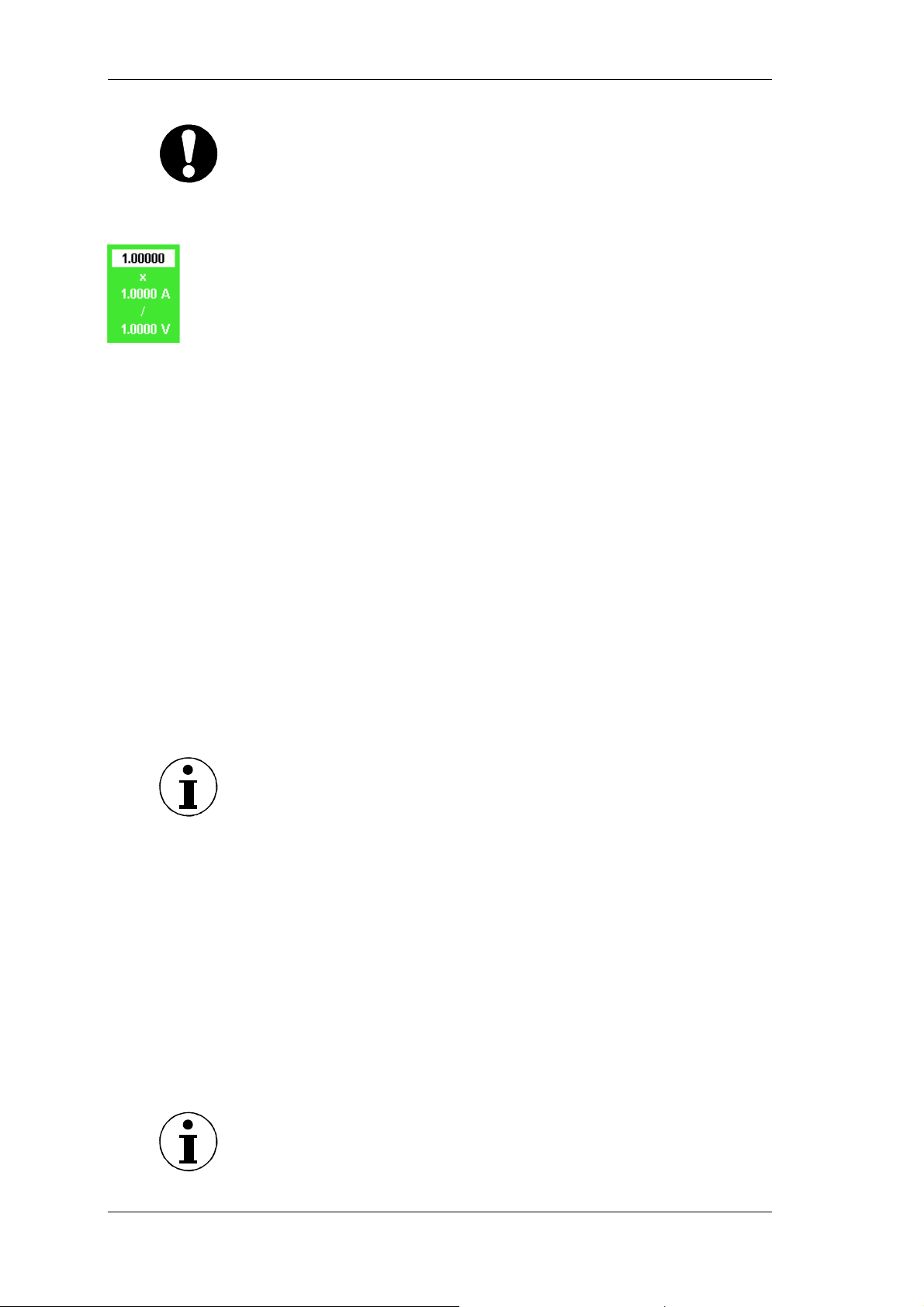
The parameters of the formula must be entered as follows:
- scale factor x transducer ratio
whereby
- scale factor: generally "1.0000" (one)
- transducer ratio: current (in ampere) to voltage (in volt)
Power Analyzer NORMA 4000, NORMA 5000 31
EO1111G REV G
Page 34
Configuration
Important
If you select Set all to apply the configuration to all channels, only
the scale factor is transferred. If shunt values U/I are entered, the
scale factor is always 1, and Set all is not available. If probes are
used, it is generally easier to enter the transducer ratio, and Set all
is thus not recommended.
Move the cursor to the value in column Scale and press Enter.
A dialog window showing the scale formula is displayed.
Select a value for each parameter and confirm with Enter.
The settings are shown in column Scale.
Save the settings with SAVE in the desired configuration.
Configure
coupling
By configuring the coupling, you determine the current you wish to
analyse. Select AC to analyse alternating currents; select DC to
analyse direct and alternating current.
Move the cursor to the field in column Coup and press Enter.
The options AC and DC are displayed.
Select AC or DC and confirm with Enter.
The settings are shown in column Coup.
If you wish to configure all three current channels in this way,
press Set All.
Save the settings with SAVE in the desired configuration.
Configure filter
The anti-aliasing filter is located in the measuring channel. It is a
prerequisite for the correct analysis of FFT data. The default
configuration is ON. The anti-aliasing filter has a cut-off frequency
of 1/10 of the sampling frequency. At half the sampling frequency,
no signal reaches the A/D converter.
Note
For broadband numerical measurements in lighting technology, set
the filter to OFF.
If measurements at high frequency are made without filter, it is not
possible to correctly analyse the signals, due to aliasing. Please
refer to chapter 7.11 ”Undersampling / Aliasing” page 37
Move the cursor to the value in column Level and press Enter.
The options AC and DC are displayed.
Select the desired value and confirm with Enter.
The entered value is shown in column Level.
If you wish to configure all three current channels in this way,
press Set All.
Save the settings with SAVE in the desired configuration.
Call up Voltage
Channel Setup
Call up Current Channel Setup.
Note
To configure the voltage channels, proceed as described for the
current channels.
32 Power Analyzer NORMA 4000, NORMA 5000
EO1111G REV G
Page 35
Configuration
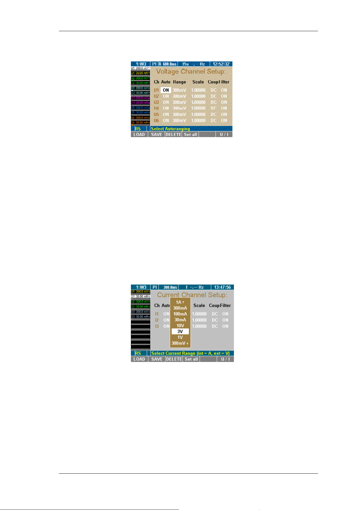
Press function key U/I.
The Voltage Channel Setup menu is displayed.
Configure voltage channels 1 to 6.
7.7 Switch current input to external input (BNC)
If you want to use an external shunt or probe you have to change
the current input from direct measurement to the BNC input. This
has to be done in the Current Channel Setup menu.
This procedure consists of the following steps:
- Call up Current Channel Setup
- Switch input
- Configure input range
- Configure scale
Switch Current
input
First filed in column Range is highlighted.
Press Enter, select a voltage range (e.g. 3V ) and confirm with
Enter.
If you wish to configure all three current channels in this way
press Set All.
Save the settings with SAVE in the desired configuration.
The current input is now changed to the external BNC input.
Configure autorange selection
First filed in column Auto is highlighted.
Press Enter, select ON and confirm with Enter.
If you wish to configure all three current channels in this way
press Set All.
Save the settings with SAVE in the desired configuration.
Auto range is now enabled.
Power Analyzer NORMA 4000, NORMA 5000 33
EO1111G REV G
Page 36
Configuration
Configure scale
If you intend to use a shunt or a probe, you must adjust the scale
for the output of the measuring signal.
Note
The correct parameter settings are shown on the type plate of the
shunt or probe.
You can ...
- enter the transducer ratio (U over I) at the external current
meters and instruct the device to calculate the final scale
factor
or
- enter the scale factor at the current transducer so that the
final scale factor can be calculated.
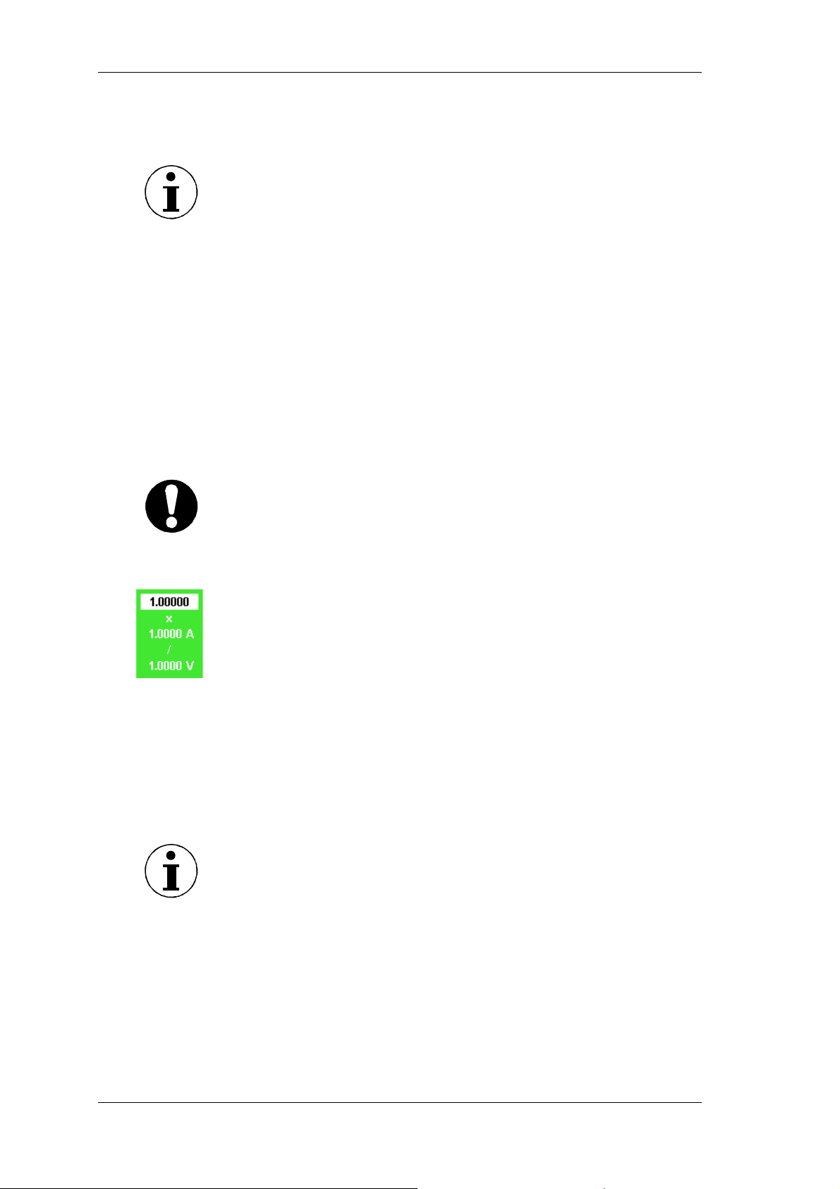
The parameters of the formula must be entered as follows:
- scale factor x transducer ratio
whereby
- scale factor: generally "1.0000" (one)
- transducer ratio: current (in ampere) to voltage (in volt)
Important
If you select Set all to apply the configuration to all channels, only
the scale factor is transferred. If shunt values U/I are entered, the
scale factor is always 1, and Set all is not available. If probes are
used, it is generally easier to enter the transducer ratio, and Set all
is thus not recommended.
Move the cursor to the value in column Scale and press
Enter.
A dialog window showing the scale formula is displayed.
Select a value for each parameter and confirm with Enter.
The settings are shown in column Scale.
Save the settings with SAVE in the desired configuration.
7.8 Integration function configuration
This configuration concern important parameters required for the
calculation of integrated values over time.
Note
You can select up to six different integration parameter (values) out
of a list. Active power P1 to P3 and the sum power are preselected.
Call up
Integration Setup
34 Power Analyzer NORMA 4000, NORMA 5000
Analyzer is switched on; start screen is displayed.
Press function key WAV.
The integration symbol is displayed in the assignment bar for
function keys.
EO1111G REV G
Page 37
Configuration
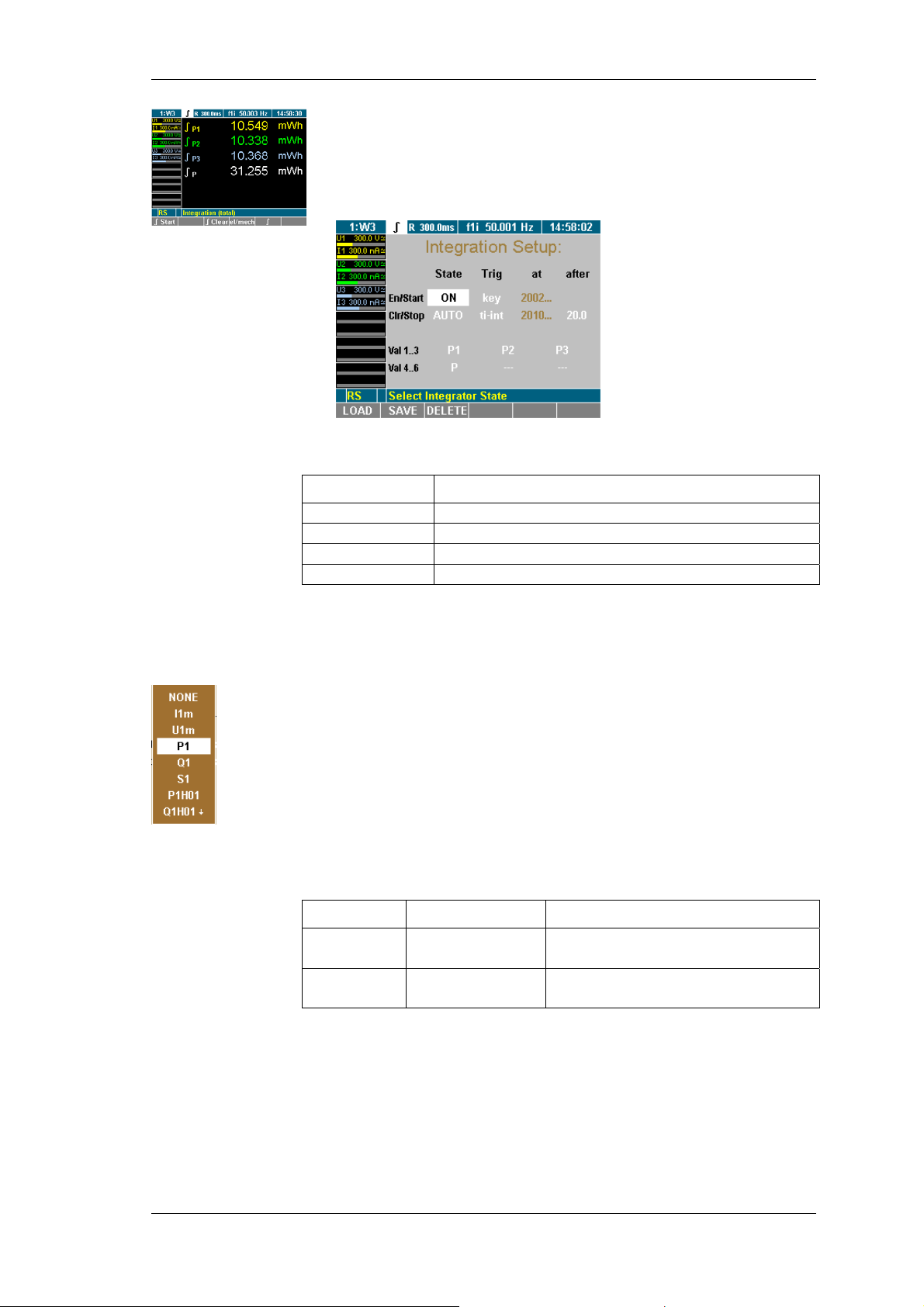
Press the function key ∫.
Integration symbol is displayed in the menu bar.
Move Cursor to ∫ display and press Enter.
The Integration Setup menu is displayed.
Select integration
value
Configure status
In the Integration Setup menu, define the following settings:
Line Function
En/Start
Clr/Stop
Val 1..3
Val 4..6
Menu Integration Setup is displayed on the screen
Enable integration function/ set start conditions
Configure data reset / set stop conditions
Select first three values
Select next three values
Select with the cursor in line Val 1..3 or Val 4..6 a value and
confirm with Enter .
A dialog window showing the selectable values is displayed.
Move the Cursor in the window to the wanted value and
confirm with Enter.
The parameter is now shown on the display
Configure the other values accordingly
Save the settings with SAVE in the desired configuration.
In this menu you can enable / disable the integration function. Also
the way of clearing the values can be configured. This is done in
the Integration Setup menu at column State.
Line Settings Description
En ON
OFF
Clr MAN
AUTO
Integration function active
Integration function inactive
Clear manual
Auto clear at start
Menu Integration Setup, first field column State is highlighted
Press Enter, select ON and confirm with Enter.
The integrations function is now enabled . If you want to
disable it, select OFF and confirm with Enter
Save the settings with SAVE in the desired configuration.
Power Analyzer NORMA 4000, NORMA 5000 35
EO1111G REV G
Page 38
Configuration
Note
The integration function is enabled (ON) in the factory configuration
1:W3 .
Menu Integration Setup, second field column State is highlighted
Press Enter, select AUTO and confirm with Enter.
Clear values at start is now enabled. If you want to change it,
select MAN and confirm with Enter
Save the settings with SAVE in the desired configuration.
Note
In the factory configuration 1:W3 the function clear manual (MAN)
is preselected.
Configure start
You can select different start conditions:
Column Settings description
Trig remote
time
key
Start via Interface command
Start on date and time
Start when key pressed (Key F1)
at -Date- Start time(only active at Trig time)
after -
No function
Menu Integration Setup, first field column Trig is highlighted
Press Enter, select start condition and confirm with Enter.
Start condition is now set. If you have selected a time to start
(time) enter the time in the column at. Proceed as described
below:
Menu Integration Setup, first field column at is highlighted
Press Enter, select year, month, day, hour minute and seconds
with the cursors and confirm with Enter.
Start time is now set.
Save the settings with SAVE in the desired configuration.
Note
Date and time for start is taken from the clock in the unit. Please
control date and time of the unit before you start the integration
calculation (7.5“Adjust date and time” page 29).
Configure stop
You can select different stop conditions:
Column Settings Description
Trig remote
time
key
ti-int
at -Date-
Stop via Interface command
Stop at date and time
Stop when key pressed (Key F2)
Stop after time window
Stop on date and time (only
active at Trig time)
after -time-
Integrations time window in sec.
((only active at Trig ti-int)
36 Power Analyzer NORMA 4000, NORMA 5000
EO1111G REV G
Page 39

Configuration
Menu Integration Setup, second field column Trig markiert
Press Enter, select stop condition and confirm with Enter.
Stop condition is now set. If you have selected a time to start
(time) enter the time in the column at. Proceed as described
below:
Menu Integration Setup, first field column at is highlighted
Press Enter, select year, month, day, hour minute and seconds
with the cursors and confirm with Enter.
Stop time is now set. If you have an integration time window
selected (ti-int) proceed as follow:
Menu Integration Setup, second field column after is
highlighted
Press Enter, select time with the cursors and confirm with
Enter.
Stop time is now set.
Save the settings with SAVE in the desired configurationPress
7.9 Save configuration
A configuration menu is displayed on the screen (for a list of
configuration menus, refer to page 22).
Press function key SAVE.
A list showing all existing configurations is displayed.
Select a configuration (e.g. 10:USER) and confirm with Enter.
The configuration is now being saved with the new name. The
name of the new configuration, e.g. 10:USER, is displayed in
the menu item.
At the next startup of the device, the last saved and loaded
configuration is applied by default.
7.10 Delete configuration
A configuration menu is displayed on the screen (for a list of
configuration menus, refer to page 22).
Press function key DELETE.
A list showing all existing configurations is displayed.
Select a configuration (e.g. 10:USER) and confirm with Enter.
The configuration is now being deleted.
Press Enter or Esc to return to the previous screen.
7.11 Undersampling / Aliasing
If you want to make signal analyses like DSO (scope) or harmonic
analyses (FFT) with a digital sampling procedures you need to
take care about Shannon’s sampling theorem which says: “The
sample frequency must be minimum double than the highest signal
frequency”. If you do not keep this rule you will get results
(frequencies or waveforms) that do not exist in truth (=Aliasing).
Power Analyzer NORMA 4000, NORMA 5000 37
EO1111G REV G
Page 40
Configuration
If you want to measure a numeric time based mean values like
rms, rectified mean, mean…you do not need to take care about
Shannon’s theorem. For the precision of the results only the
number of samples is important, not the sampling frequency
(average time >> cycle duration). But you have to consider that the
sampling signal must be statistical independent, that means the
sampling frequency must not be close or a multiple of the signal
frequency.
Note
To work in the “undersampling mode” the anti-aliasing filter has to
be turned OFF at the current and voltage channel (see chapter 7.6
“Configure current and voltage channels“ page: 30).
38 Power Analyzer NORMA 4000, NORMA 5000
EO1111G REV G
Page 41
Measuring process
8 Measuring process
The power analyzer is designed for the measuring of currents and
voltages through up to three different channels. It calculates rms
values, real, apparent and idle power and other derived values.
The accuracy is thereby not affected by the wave form, frequency
or phase shift. Harmonics are output to maximum half the
sampling frequency.
You have the option to apply the default settings or a user-defined
configuration. If you wish to use a user-defined configuration, you
must first define and save the respective settings and then load the
relevant configuration (see chapter 7: "Configuration", page 22).
The power analyzer begins to measure as soon as the measuring
arrangement is set up and the device is switched on.
8.1 Prior to measuring
Connect power analyzer to the mains socket.
Check the measuring connections at the power analyzer.
Switch on the power analyzer.
Measuring with
default
configuration
Measuring with
user-defined
configuration
If you want to complete an analysis using the default configuration,
no additional steps are required.
Ensure that the factory configuration is loaded (see chapter
7.2: "Load configuration", page 23).
If you want to complete an analysis using a user-defined
configuration, load the respective configuration see chapter 7
"Configuration", page 22).
Important
If you want to measure with external shunt or probe please make
sure that there is no signal connected at the direct current inputs.
Signals on both inputs (external- and direct current input) can
damage the measurement unit.
Power Analyzer NORMA 4000, NORMA 5000 39
EO1111G REV G
Page 42
Measuring process
V
V
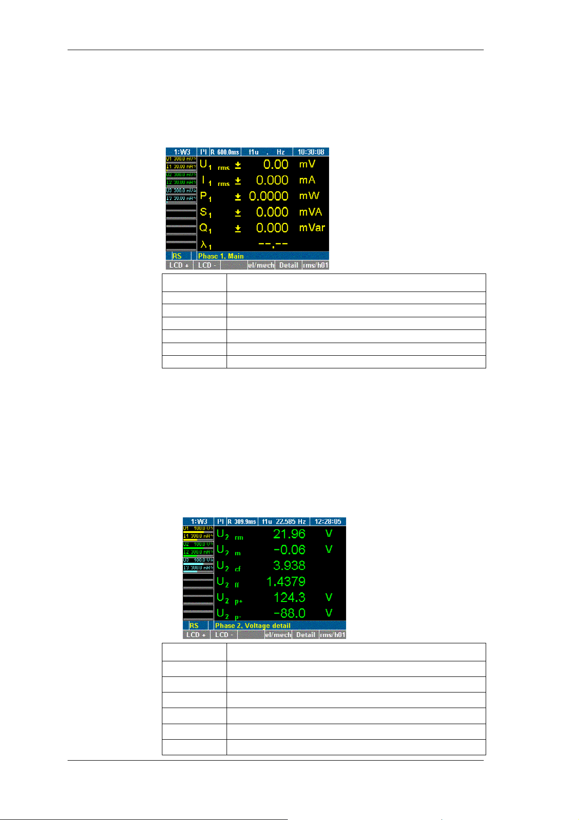
8.2 Measure voltage, current and power
8.2.1 View the measured values for the individual channels
iew the values
of one channel
iew detailed
values of one
channel
After switching on the power analyzer, the display shows the
numerical values measured in channel 1.
Display Description
U
I
1 rms
P1
S1
Q1
λ1
1 rms
rms voltage value
rms current value
Real power
Apparent power
Idle power
Power factor lambda (cap. or ind.)
Press measuring keys 1...n to view the values of the respective
channels.
You have the option to view detailed data regarding the measured
values of a channel.
Press measuring keys 1...n to view the measured values of the
respective channel.
Press function key Detail.
Details regarding the voltage values, e.g. for channel 2, are
shown.
Display Description
U
2 rm
U
2 m
U
2 cf
U
2 ff
U
2 p+
U
2 p-
Rectified mean value
Mean value
Crest factor
Form factor
Positive peak value
Negative peak value
40 Power Analyzer NORMA 4000, NORMA 5000
EO1111G REV G
Page 43
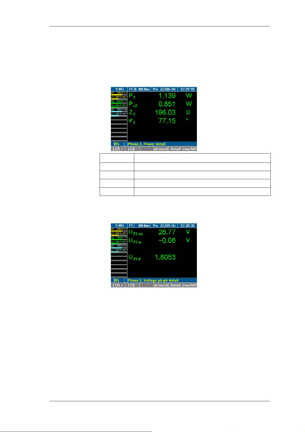
Measuring process
Press function key Detail again.
Details regarding the current values are displayed. The
equivalent parameters to those shown above for voltage are
displayed.
Press function key Detail again.
Details regarding the power values, e.g. for channel 2, are
shown.
Display Description
P2
Pc2
Z2
φ2
Power
Corrected power
Apparent impedance
Angle between U2 and I2
Press function key Detail again.
Details regarding the measured values for phase-to-phase
voltage are displayed.
To return to the measured values for channel 2, press function
key Detail again.
Power Analyzer NORMA 4000, NORMA 5000 41
EO1111G REV G
Page 44
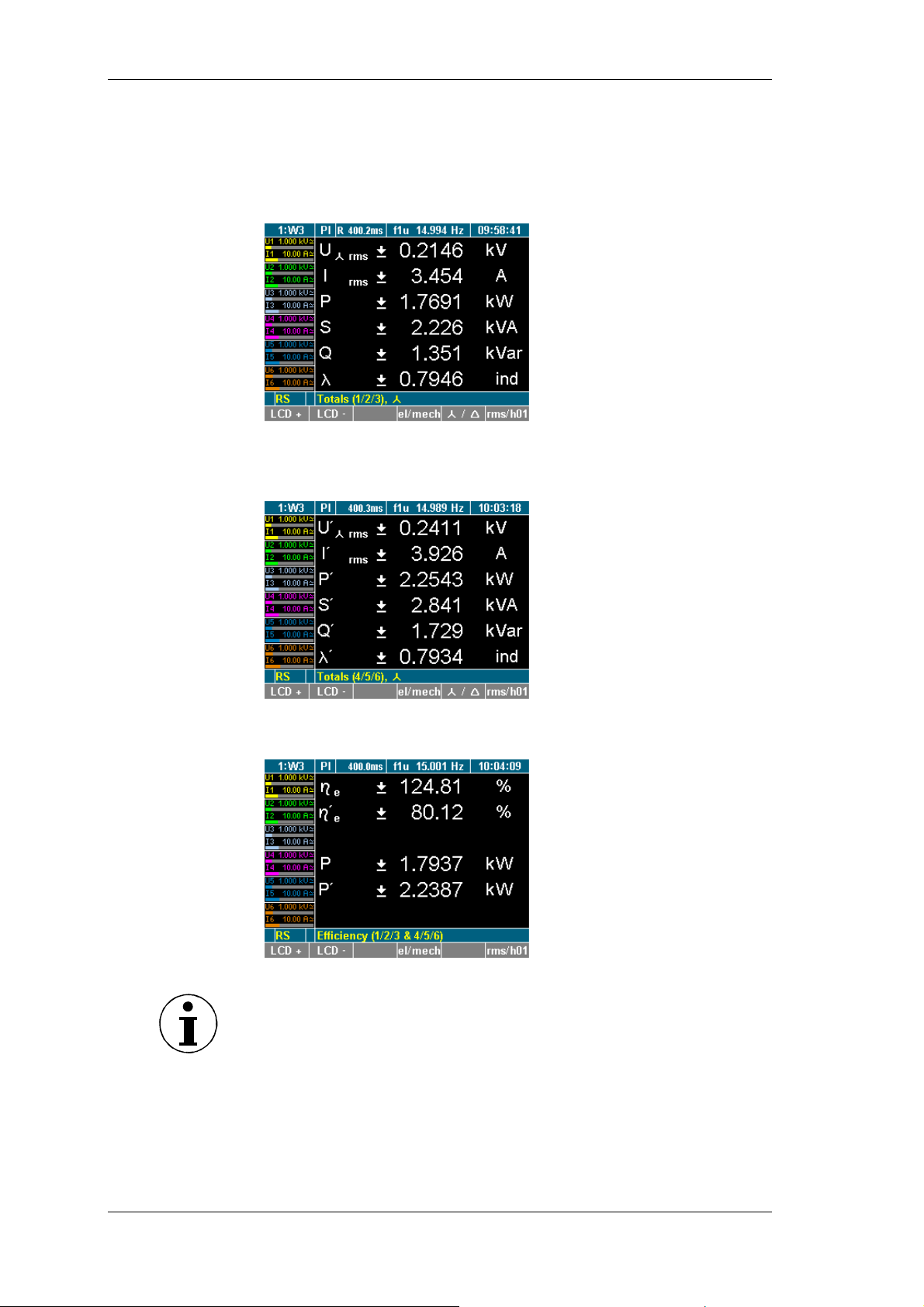
Measuring process
V
V
8.2.2 View totals of all measured values
iew totals
Press measuring key ∑.
The totals of the measured values of the first three channels
are displayed (channel 1-3).
iew efficiency
Press measuring key ∑. again
The totals of the measured values of the second three channels
are displayed (P channel 4-6).
Press measuring key ∑. three times (or again)
The efficiency and the total active power are displayed.
Note
The efficiency screen and totals channels 4-6 screen only appear if
there are 4 to 6 power phases equipped
42 Power Analyzer NORMA 4000, NORMA 5000
EO1111G REV G
Page 45
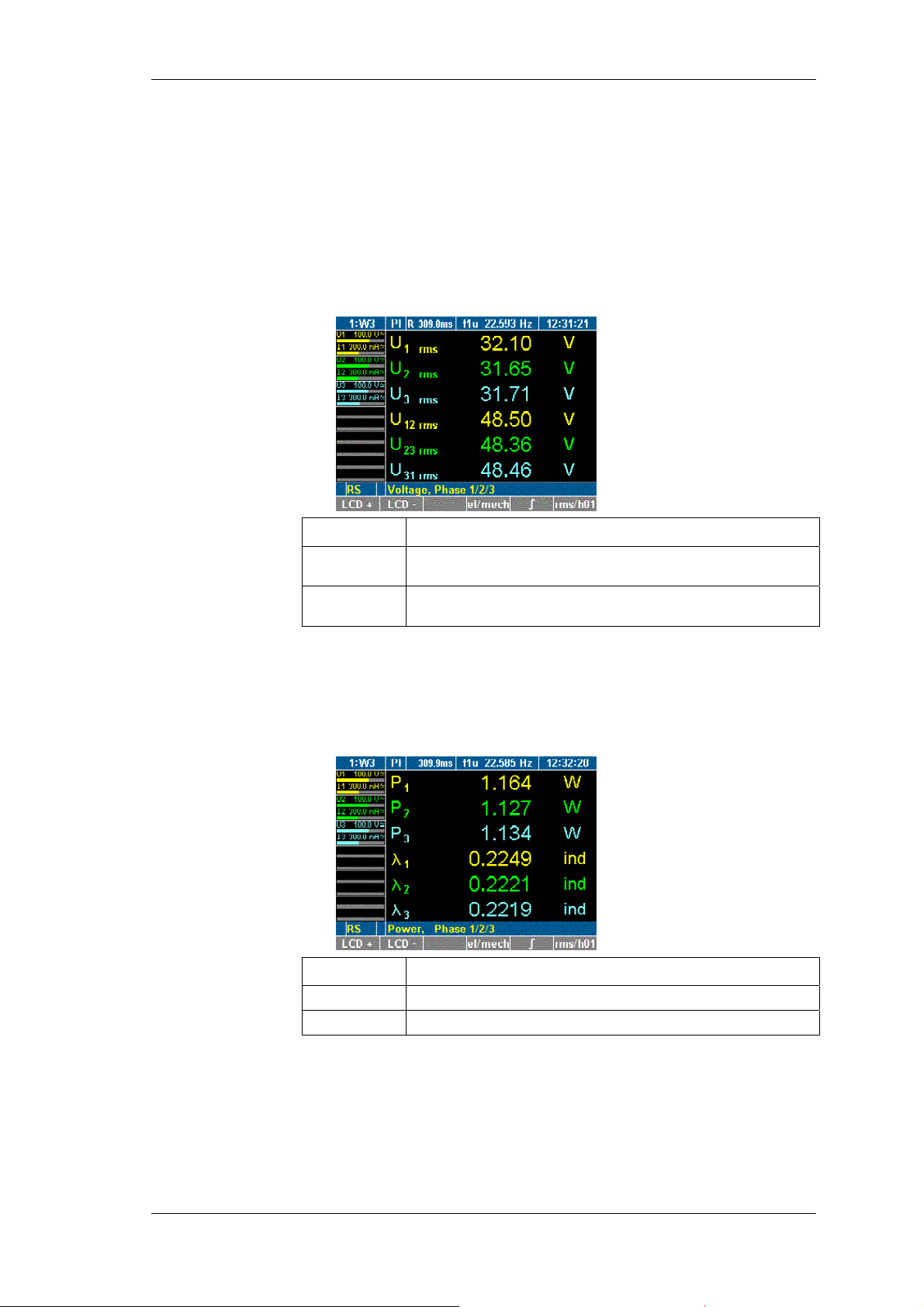
Measuring process
8.2.3 Compare measured values
Compare
measured values
You have the option to compare the values measured at the
different channels, e.g. all voltages measured at all channels.
When pressing measuring key WAV, the comparative display
switches from voltage to current and power, showing the
respective values of all three channels.
Press measuring key WAV.
The measured voltages and phase-to-phase voltages are
displayed.
Display Description
U
U
U
U
1 rms
3 rms
12 rms
31 rms
...
...
rms voltage at channels 1 to 3
Phase-to-phase voltage at channels 1/2, 2/3 and 3/1
Press key WAV again.
The measured current values I1 to I3 for the three channels
are displayed.
Press key WAV again.
The power and power factor values are displayed.
Display Description
P1 ... P3
λ1 ... λ3
Power at channels 1 to 3
Power factors at channels 1 to 3
To select channels 4 to 6, repeatedly press key WAV.
Power Analyzer NORMA 4000, NORMA 5000 43
EO1111G REV G
Page 46
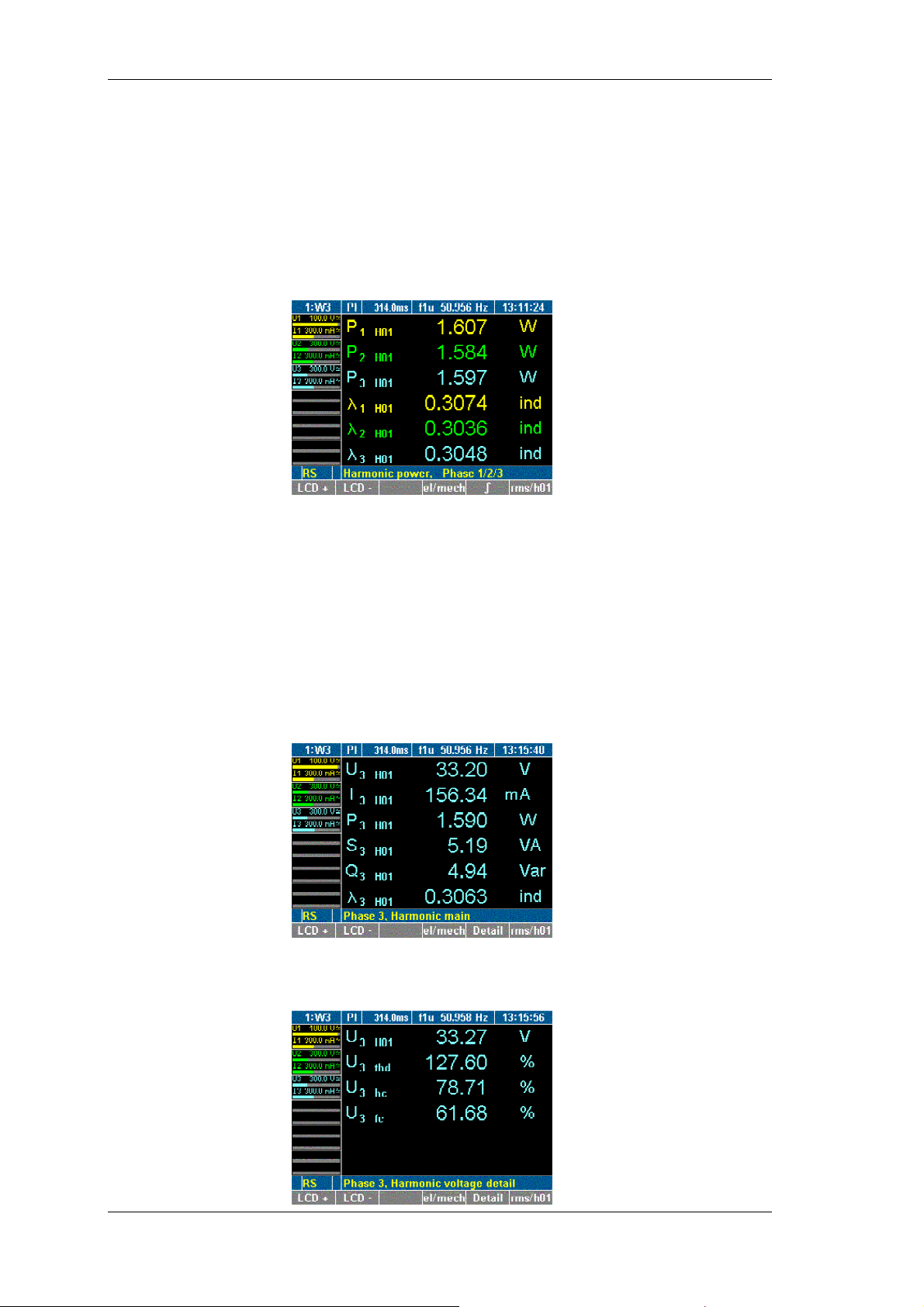
Measuring process
V
V
8.2.4 View fundamentals
iew
fundamentals
For each measured value, the power analyzer calculates the
fundamental by means of Fourier transformation (DFT).
Press measuring keys ∑ or 1...n and WAV to call up the
desired values, e.g. power at channels 1 to 3.
Press function key rms/h01.
The power of the fundamentals is displayed.
To return to the power values, press function key rms/h01
again.
iew details of
fundamentals
You have the option to view detailed data regarding a
fundamental, such as voltage, current, power and phase-to-phase
voltage.
Press measuring keys ∑ or 1...n and WAV to call up the
desired values, e.g. values measured at channels 3.
Press function key rms/h01.
Detailed measured values in connection with the fundamentals
at channel 3 are shown.
Press function key Detail.
Details of the voltage of the fundamental at channel 3 are
shown.
44 Power Analyzer NORMA 4000, NORMA 5000
EO1111G REV G
Page 47
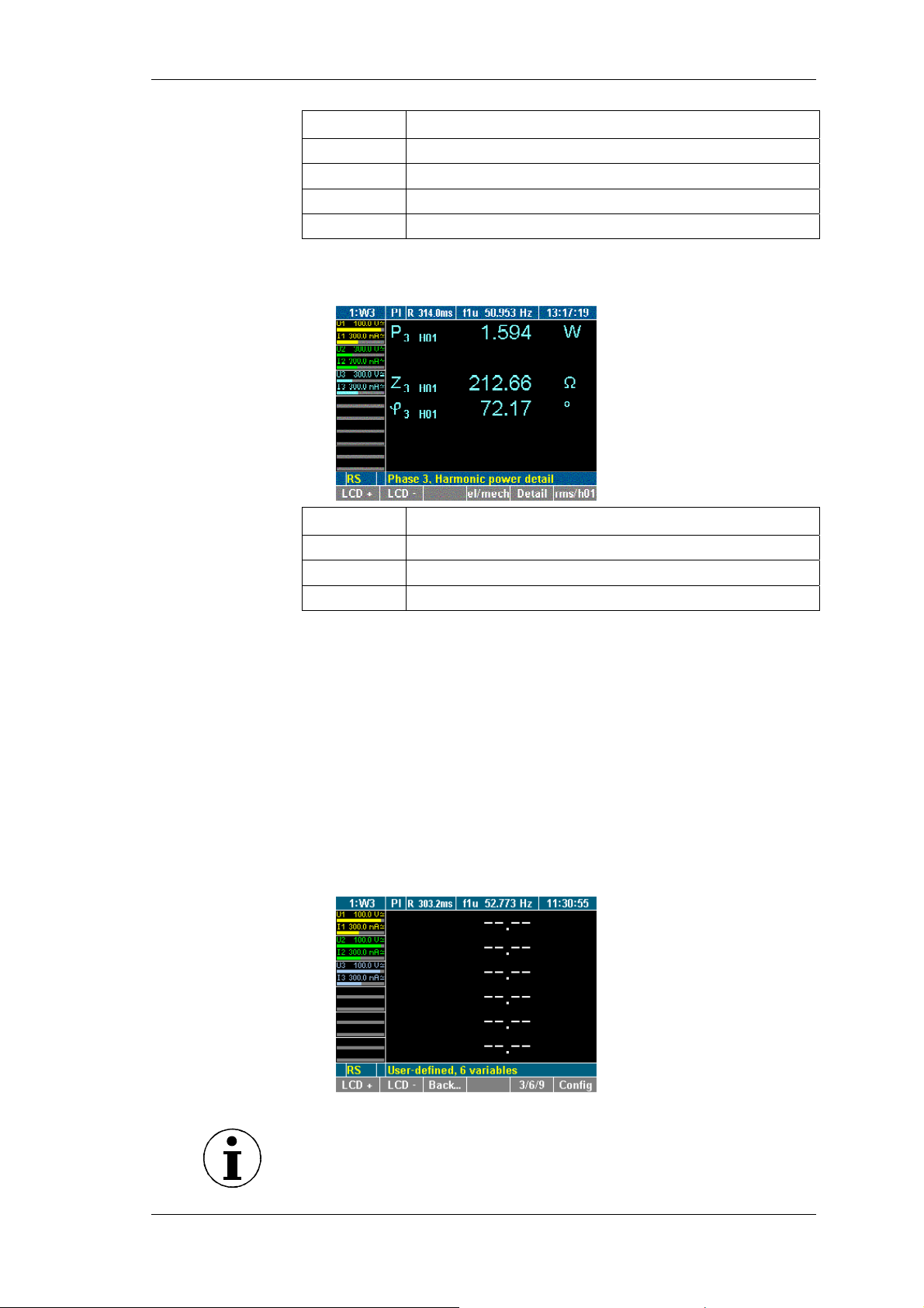
Measuring process
V
Display Description
U
U
U
U
2 H01
2 thd
2 hc
2 fc
rms value of fundamental
Total harmonic distortion (according to IEC)
Harmonic content (according to DIN)
Fundamental content
Press function key Detail twice.
Details of the power of the fundamental at channel 3 are
shown.
Display Description
iew user defined
screen
P
Z
φ
2 H01
2 H01
2 H01
Power of fundamental
Apparent impedance of fundamental
Angle between U3 and I3 of fundamental
To return to the display of the fundamentals for channel 3,
press function key Detail twice.
To return to the measured values for channel 3, press function
key rms/h01 again.
8.2.5 User defined screen view
In this menu you can configure your own defined numeric screen.
Furthermore you can change this user defined screen to get 3, 6 or
even 9 values displayed on one screen.
Press function key User
The display shows the user defined screen.
Note
If you enter the user defined screen the first time it is empty,
showing dashes. In all other cases it shows the last saved
configuration or the recently selected values.
Power Analyzer NORMA 4000, NORMA 5000 45
EO1111G REV G
Page 48
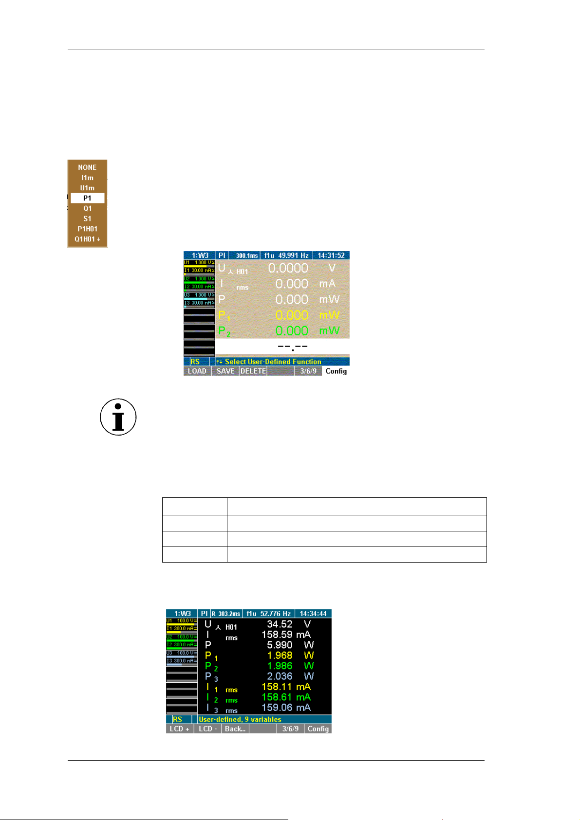
Measuring process
Select numeric
values
You can select values out of list of more than 450 variables
depending with how many channels the unit has equipped.
Press function key Config
The configuration menu is shown.
Select desired row with the Cursor and confirm with Enter.
A dialog window showing the selectable values is displayed
Select desired values with the cursor (up/down and left/right)
and confirm with Enter.
The selected values are shown on the display.
Repeat until all desired values are on the display screen
Press Esc to leave the configuration menu
Change user
defined display
size
Note
You can configure and display up to nine variables (values). Please
change the user defined display size (see “Change user defined
display size” below) to configure all nine values.
You can change the size of the numeric display in the user defined
screen. You can select between three sizes:
size description
3
6
9
3 numeric values, double size
6 numeric values, common size (7mm)
9 numeric values, with size 5mm
Press function key 3/6/9
User defined values are shown in desired size .
46 Power Analyzer NORMA 4000, NORMA 5000
EO1111G REV G
Page 49
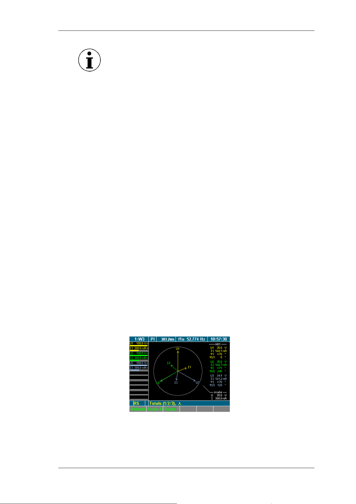
Measuring process
V
Note
The changing of the display size is done in a loop, every time you
press the function key 3/6/9.
You can change the size in the configuration menu and also in the
measurement menu.
Save user
defined screen
Save the settings with SAVE in the desired configuration
See details about saving a configuration in chapter 7.9 Save
configuration
Back to common
numeric screen
Press function keys Back... or Esc
The recently used numeric screen is shown.
8.3 Change view mode
After having selected a channel and the relevant measured values,
you have the option to change to different view modes where the
parameters are shown in the form of numerical values, vector
graphs or oscilloscope graphs.
iew vector
graphs
8.3.1 Numerical display
For details regarding the numerical display of measured values,
refer to chapter 8.2 "Measure voltage, current and power", page 40
8.3.2 Vector graphs
Up to 6 signals of the H01 fundamentals can be viewed as vector
graphs.
The vector graphs show voltage and current with amplitude and
phase shift, and allow fro the fast assessment of signals and
detection of errors in the connections.
∑
Press measuring keys
or 1...n and WAV to call up the
desired values, e.g. values measured at WAV power.
Press measuring key Vector graphs.
The measured values are shown in the form of vector graphs.
Power Analyzer NORMA 4000, NORMA 5000 47
EO1111G REV G
Page 50
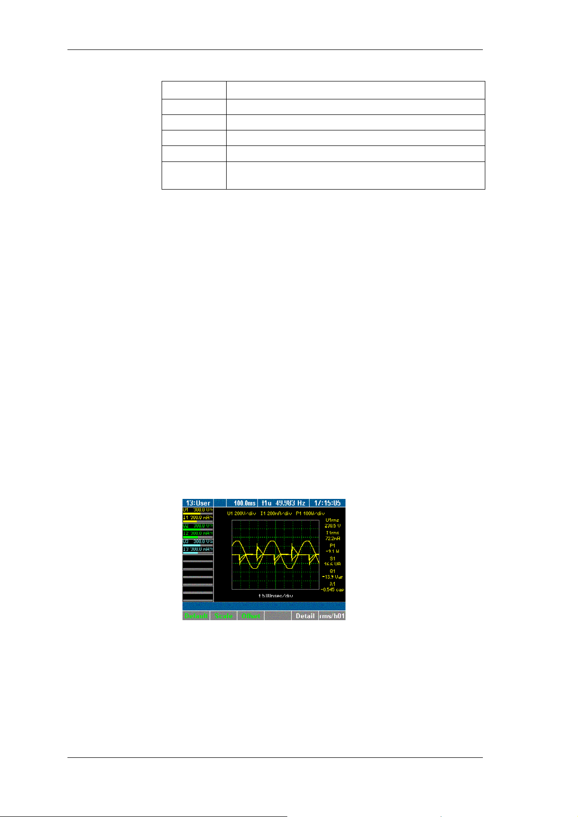
Measuring process
V
Display Description
Adjust scale
iew
oscilloscope
display
φ1 ... φ3
φU1
φU2
φU3
scale
Phase angle between U and I
... reference point (always = 0)
Angle between U2 and U1
Angle between U3 and U1
Range (reference value for the diameter of the outer
circle)
To view a different channel or different measured values in
∑
vector graph form, press measuring keys
or 1...n and WAV.
The scale of the vector in the vector diagram can de zoomed.
To automatically optimise the scale of the graph, press
function key Default.
The scale is set to the measurement range.
To change the scale of the axes, press function key Scale U or
Scale I.
Adjust the scale, using the cursor keys up / down press Enter
to confirm or Esc to exit. I.
8.3.3 Oscilloscope curves
The digital oscilloscope function (DSO) allows for display of signals
in curves, so that signal distortions can be quickly detected.
Press measuring keys ∑ or 1...n and WAV to call up the
desired values, e.g. values measured at channels 1.
Press measuring key Oscilloscope curves.
The measured values are shown in the form of oscilloscope
curves.
To view the details regarding a measured value, press function
key Detail.
The display shows the measured voltage.
48 Power Analyzer NORMA 4000, NORMA 5000
EO1111G REV G
Page 51
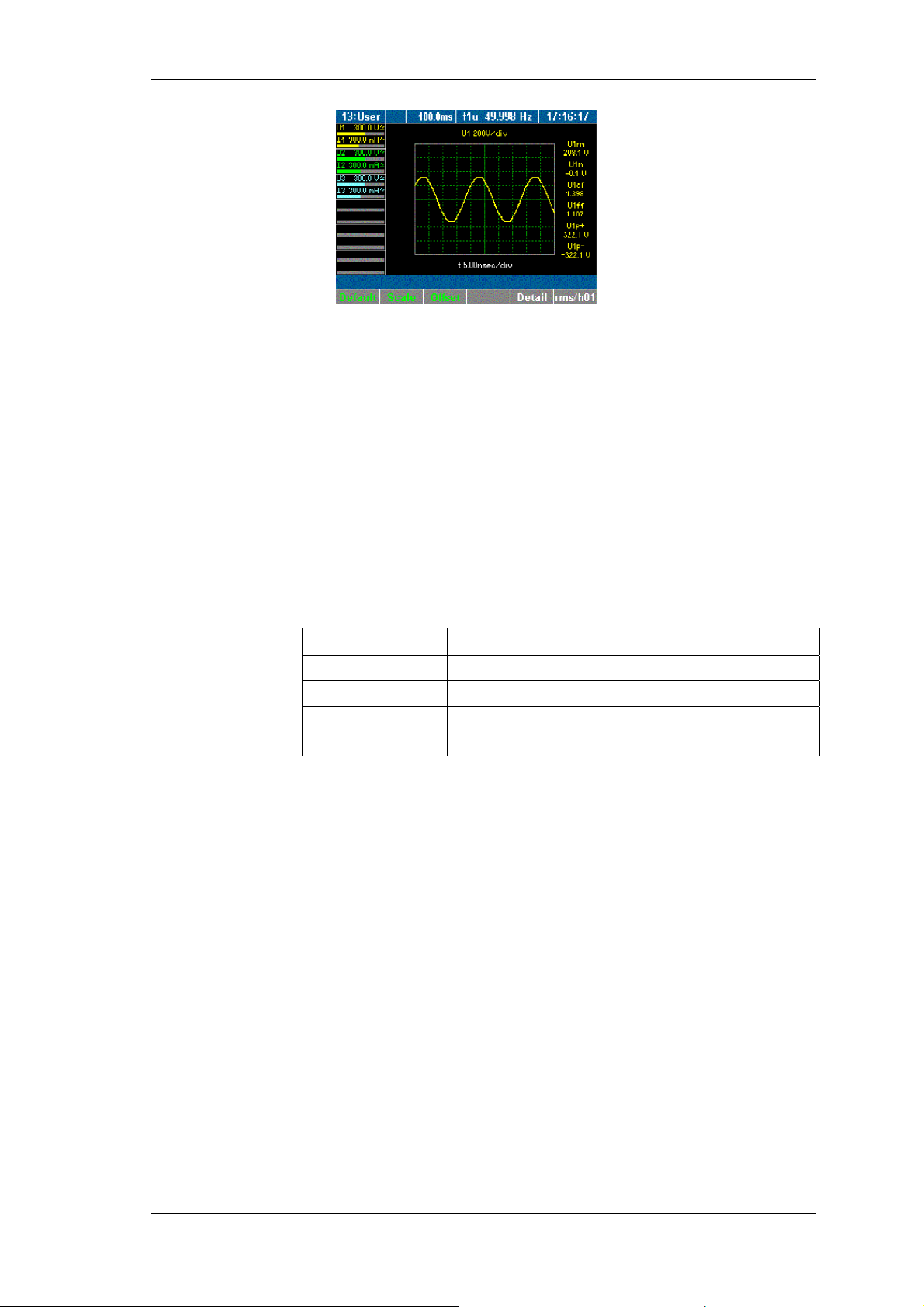
Measuring process
V
To view a different measure parameter, press function key
Detail again.
To return to an overview of all measured values for channel 1
in oscilloscope format, press function key Detail again.
To view a different channel or different measured values in
∑
oscilloscope graph form, press measuring keys
or 1...n and
WAV.
Adjust axial scale
The oscilloscope display can be optimised in a number of ways.
To automatically optimise the scale of the graph, press function
key Default.
The scale is set to steps of 5 ms.
To change the scale of the axes, press function key Scale.
Adjust the scale, using the cursor keys as described below:
Cursor key Function
left, right
up, down
Enter
Esc
Adjust scale of time axis
Adjust scale of amplitude axis
Confirm settings
Exit scale mode
Adjust the scale of the axes, using the cursor keys, and press
Enter and Esc.
The oscilloscope display with the adjusted axes is shown.
Adjust zero
Press function key Offset.
Adjust the zero point by using the cursor keys and confirm with
Enter.
The oscilloscope display with the adjusted zero point is shown.
8.3.4 Recorder view
The recorder allows you to monitor measured values, by recording
the mean measured values over time. This function is particularly
useful for the detection of trends and amplitude variations. The
actual graph depends on the configured range and average time
(see chapter 7.1 "Call up General Setup", page 23). Prominent
variations in the graph indicate errors in the measuring system.
iew recorder
Press measuring keys
∑
or 1...n and WAV to call up the
desired values, e.g. current measured at channels 1 to 3.
Press measuring key Recorder.
The display shows a recording of the measured values.
Power Analyzer NORMA 4000, NORMA 5000 49
EO1111G REV G
Page 52
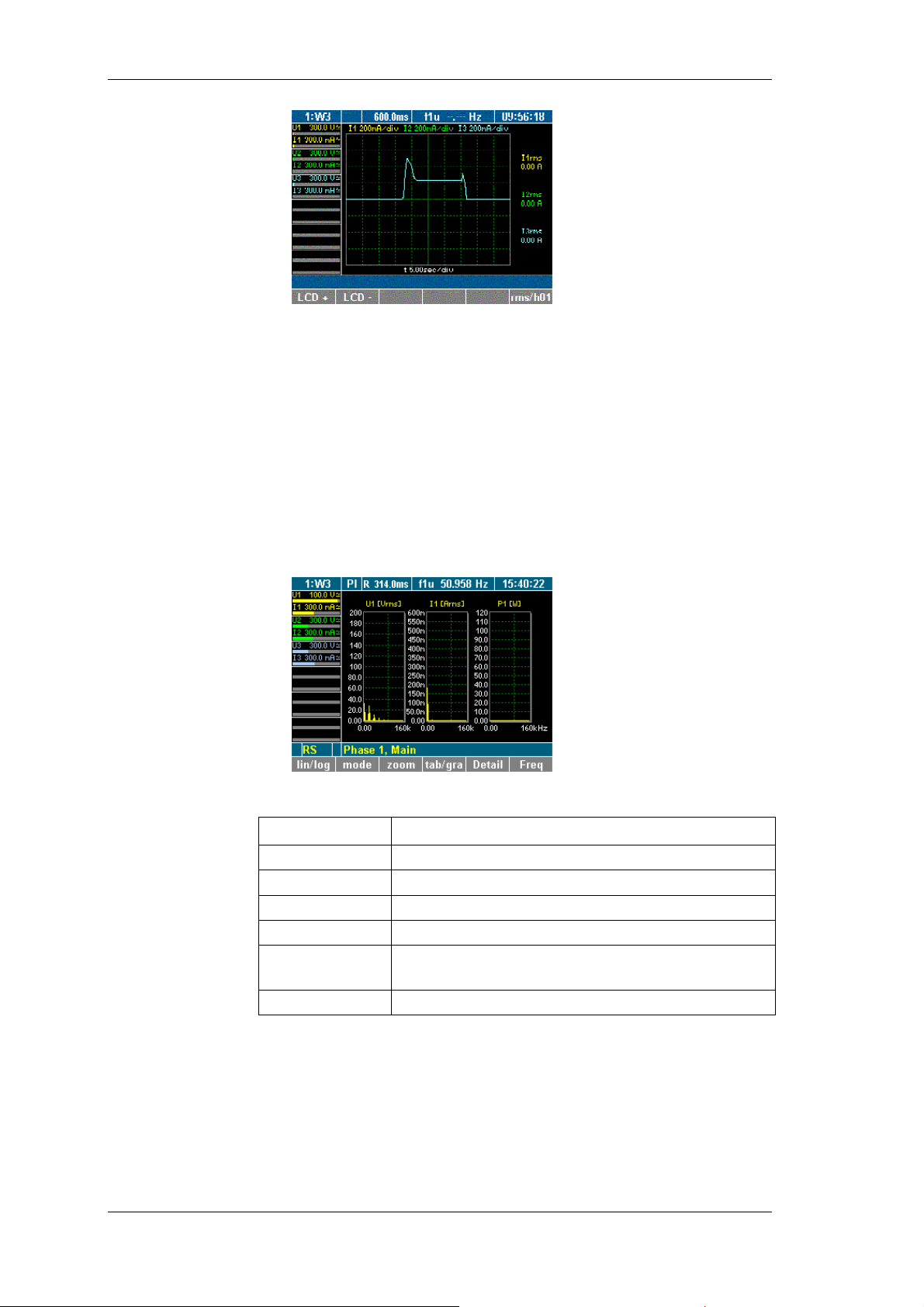
Measuring process
drücken Sie nochmals die Funktionstaste rms/h01.
8.4 Fast Fourier analysis
Fast Fourier transformation (FFT) allows for the analysis of the
individual frequency components of a signal. The harmonics may
be viewed in graphical or tabluar format as percentages of
fundamental H01.
Press measuring keys 1...n to call up the desired values, e.g.
values measured at channels 1.
Press measuring key Fast Fourier analysis.
The frequency analysis is shown.
Adjust scale
The following function keys are available:
Function key Description
lin/log
mode
zoom
tab/gra
Detail
Switch between linear and logarithmic Y axis
View harmonics
Shift X axis
Switch between table and graphic display
Switch between U, I and P of one phase; switch
between displays of 1 or 3 values
Freq
Select frequency range
8.4.1 FFT mode
You have the option choose between a linear or logarithmic Y-axis.
By using the cursor keys, you can adjust the positions of the axes.
Press function key lin/log.
The scale of the graph changes from linear to logarithmic or
vice versa (here: change to logarithmic).
50 Power Analyzer NORMA 4000, NORMA 5000
EO1111G REV G
Page 53
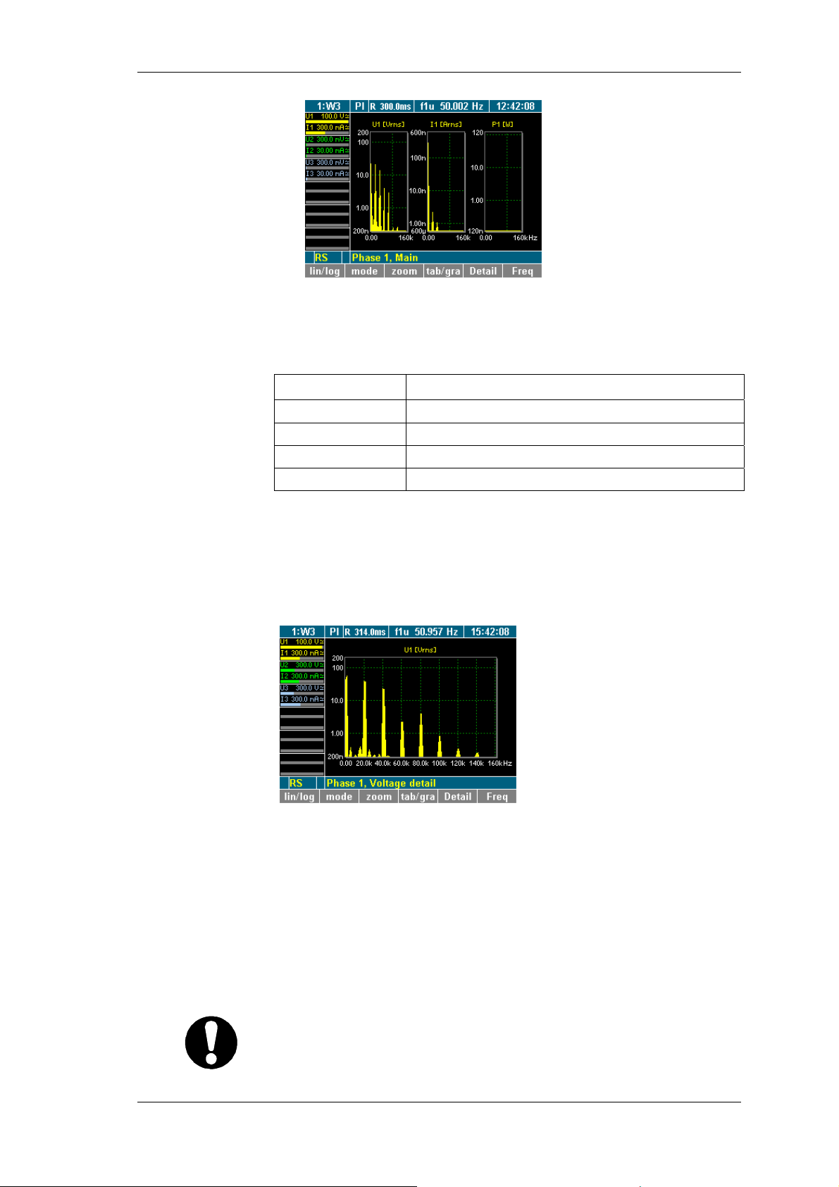
Measuring process
V
To change the scale of the axes, press function key Zoom.
Adjust the scale, using the cursor keys:
Cursor key Function
iew details of a
measured value
Set frequency
range
left, right
up, down
Enter
Esc
Shift frequency axis
Change frequency
Confirm settings
Exit scale mode
Adjust the scale of the axes, using the cursor keys, and press
Enter and Esc.
The graph with the adjusted axes is shown.
Press function key Detail.
The details of measured value U1 (voltage) are displayed.
Press function key Detail again.
The details of measured value I1 (current) are displayed.
Press function key Detail again.
The details of measured value P1 (power) are displayed.
To return to the overview of measured values of the selected
channel, press function key Detail again.
The default frequency range is set to maximum half of the
sampling frequency.
Important
For signals with a lower frequency (e.g. 10 Hz), the frequency
range must be adjusted, as measurements would otherwise be
inaccurate.
Power Analyzer NORMA 4000, NORMA 5000 51
EO1111G REV G
Page 54
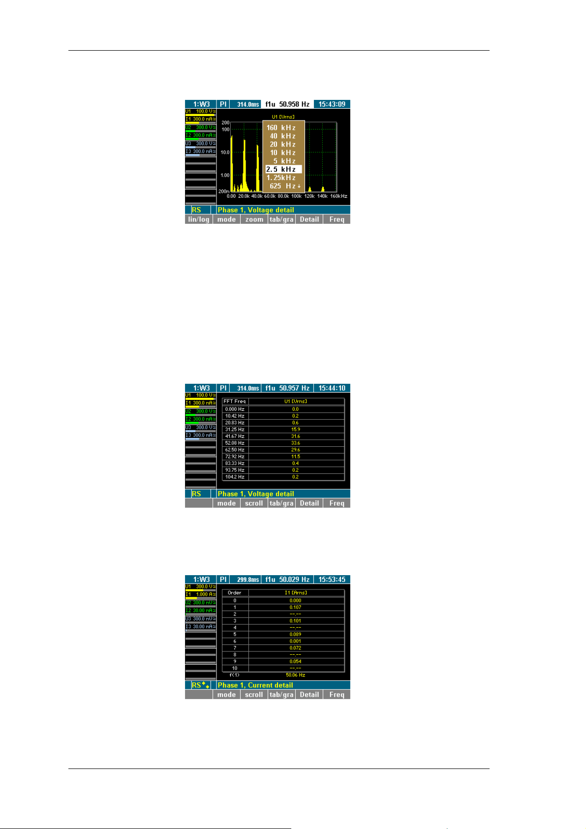
Measuring process
V
Press function key Freq.
A list of possible values is displayed.
Select a value, using the cursor keys, and press Enter.
The frequency analysis is carried out up to the selected value,
and the result is displayed.
Change view
mode
You have the option to view individual measured values or a group
of up to three values (e.g. all measured values of channel 1) in
graphic or table format. By default, the measured values are
shown in graphic format.
Press function key tab/gra.
The raw data is now shown in a table (here: voltage on
channel 1).
8.4.2 Harmonic Order mode
iew harmonics
Press function key mode to call up a table showing the
harmonics.
The table shows the integer harmonics (here: voltages of the
individual harmonics on channel 1).
52 Power Analyzer NORMA 4000, NORMA 5000
EO1111G REV G
Page 55
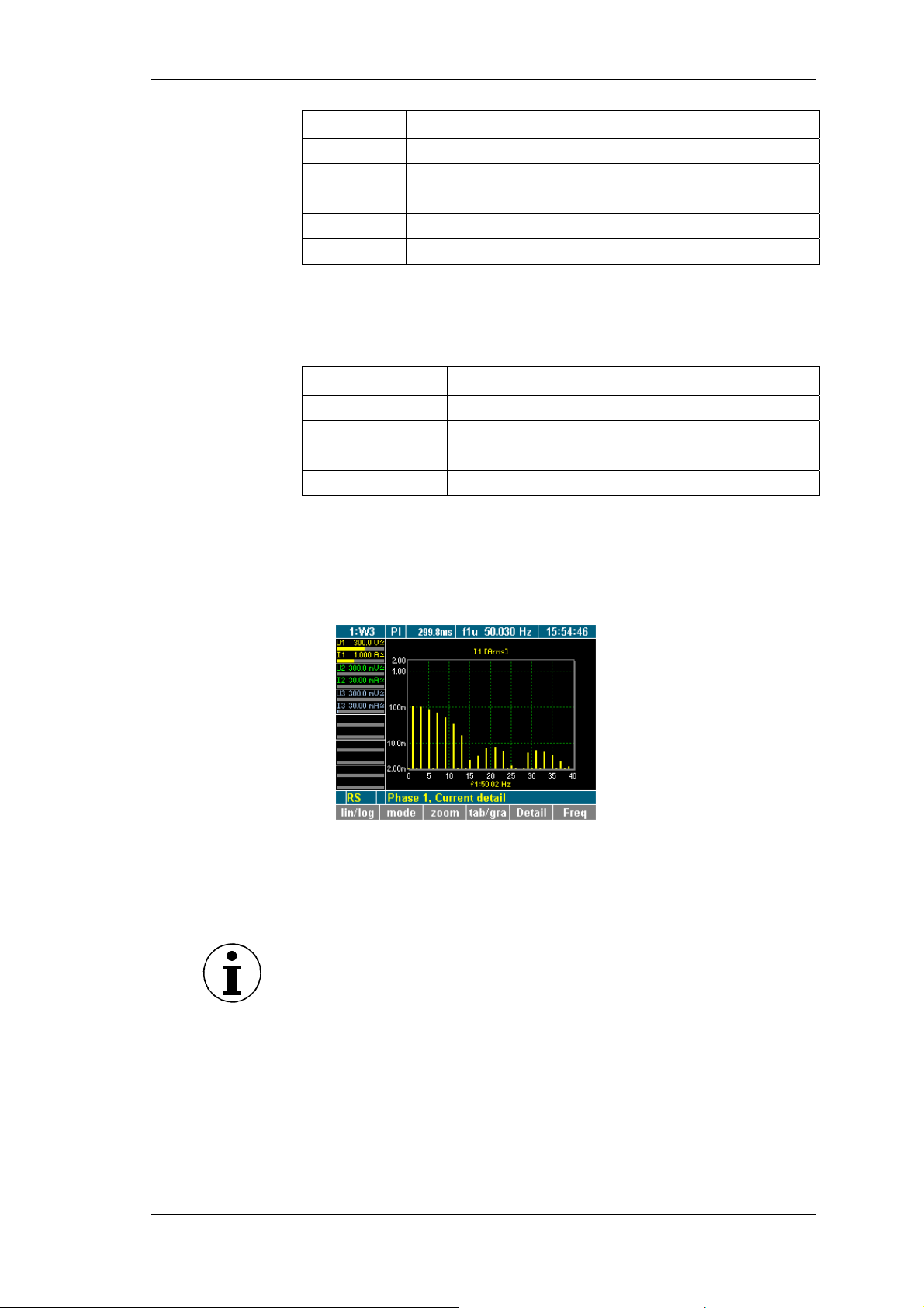
Measuring process
V
Display Description
Order 0
Order 1
Order 2
Order 3
Order ...
DC content
Fundamental
2 x fundamental frequency
3 x fundamental frequency
n x fundamental frequency
Press function key scroll to enable scrolling and paging
through the table.
To scroll and page, use the cursor keys:
Cursor key Function
left, right
up, down
Enter
Esc
Page through table (screen by screen)
Scroll through table (line by line)
Confirm view and exit scale mode
Exit scale mode
When you have reached the table section you wish to study in
more detail, press Enter or Esc.
The selected table section is now displayed.
To change to a graphic display of the harmonics, press
function key tab/gra.
8.4.3 Harmonic Order mode related to fundamental in %
iew spectrum
relative to H01
The harmonic spectrum can be viewed in percentages of
fundamental H01.
Note
This view is important for the analysis of the input signal.
Press function key mode.
Power Analyzer NORMA 4000, NORMA 5000 53
EO1111G REV G
Page 56
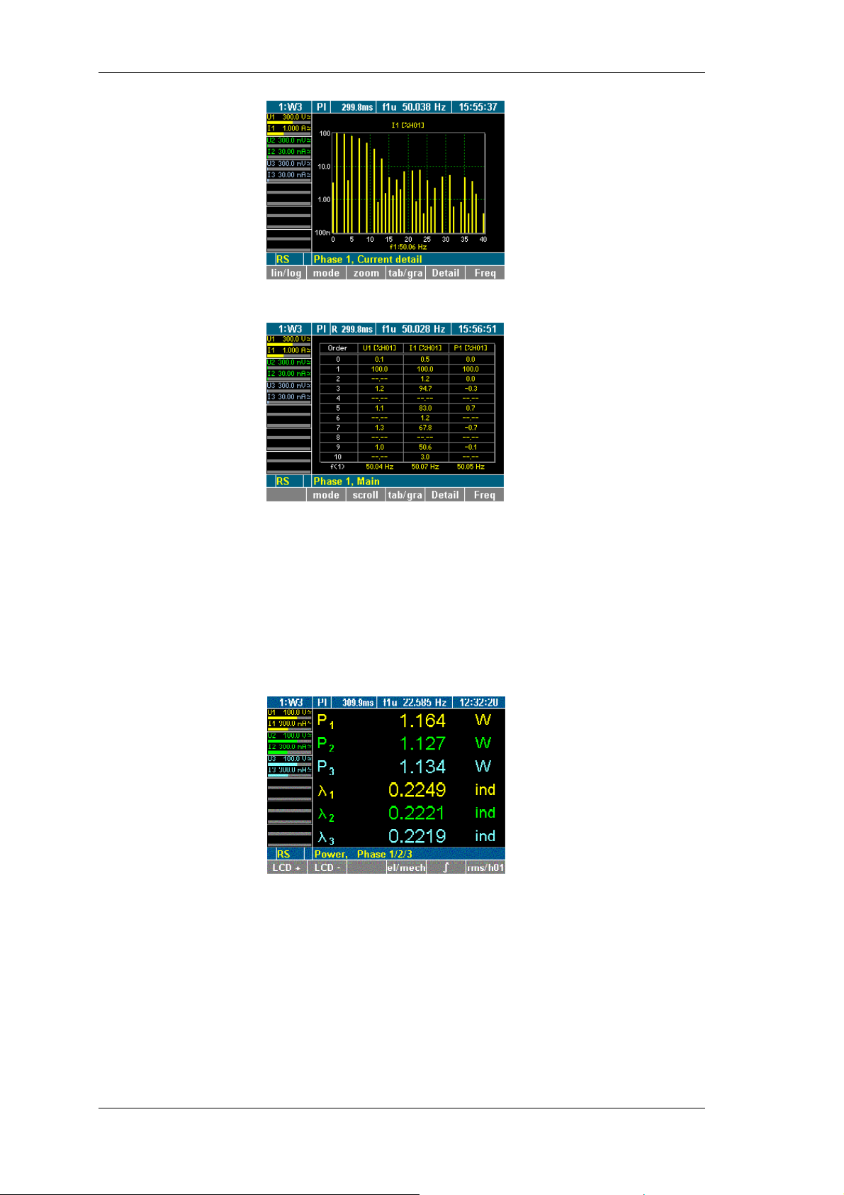
Measuring process
To change to the table view of the spectrum, press function
key tab/gra.
8.5 Integration function / electrical work
For the calculation of integrated values the values are measured
over time. You can configure up to six independent values (Um,
Im, S, P, Q) for the calculation.
Press measuring key WAV.
A key for the calculation of the electrical work is shown in the
assignment bar for function keys.
Press function key ∫.
The assignment bar shows the functions used for the
calculation.
54 Power Analyzer NORMA 4000, NORMA 5000
EO1111G REV G
Page 57
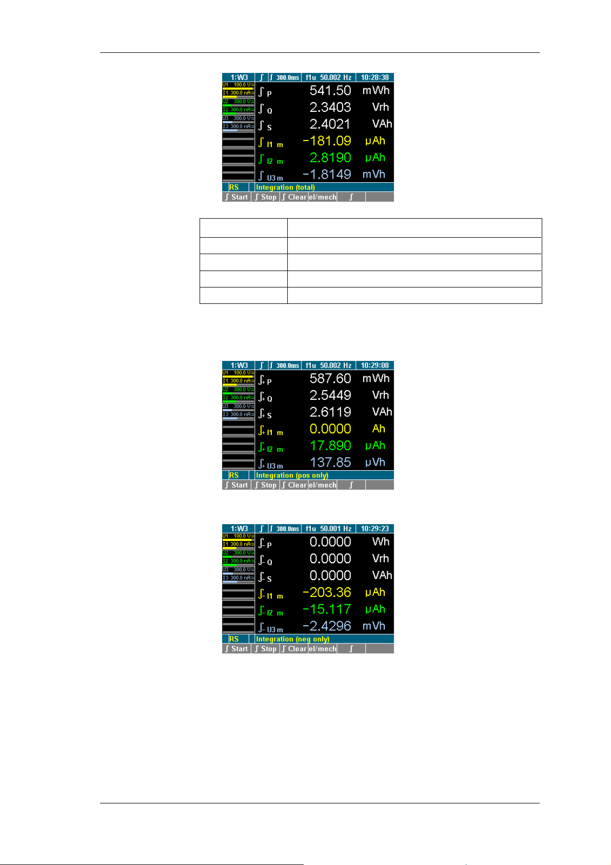
Measuring process
Function key Function
∫ Start
∫ Stop
∫ Clear
∫
Start measurement (integration)
Stop measurement (integration)
Reset measurement (integration) to zero
Change to display of measured values
Press function key ∫ Start to start the measuring process.
Press function key ∫ Stop to stop the measuring process.
The totals of the reference power are shown.
Press function key ∫.
The totals of the output power are shown.
To return to the overview of measured values for the selected
channel, press function key ∫ again.
Power Analyzer NORMA 4000, NORMA 5000 55
EO1111G REV G
Page 58
Measuring process
8.6 Save and print measurements
8.6.1 Save measurements
You have the option to save the sampling values or measurements
for later offline analyses, e.g. FFT, average startup currents or
transient processes.
Note
Measuring key Storage works only in conjunction with PowerView
Storage or NormaX software.
For more details, please refer to the user manuals of the
respective software product.
8.6.2 Print measurements
Check whether a printer is connected.
Ensure that the interface is properly configured (see chapter
7.3: "Configure data transfer to printer and PC", page 23.)
Press measuring key Print.
The measured values are printed.
56 Power Analyzer NORMA 4000, NORMA 5000
EO1111G REV G
Page 59
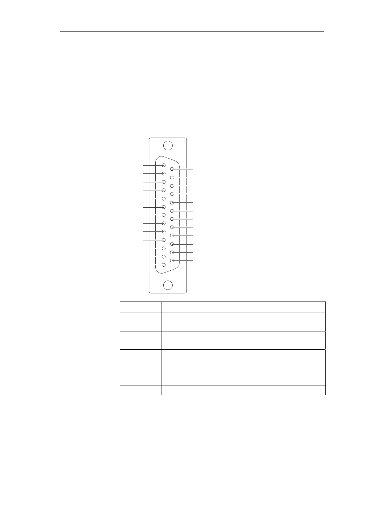
PI1 Process Interface (optional)
9 PI1 Process Interface (optional)
The PI1 interface allows you to simultaneously analyse the
electrical and mechanical power of up to 4 motors (generators).
The torque and rotational speed are thereby measured as analog
signals or via frequency inputs.
9.1 Pin assignment
The PI1 is located on the rear panel of the power analyzer (see
chapter 3 "Design and functions", page 7).
1
13
14
25
M 1–
N 1–
M 2+
N 2+
D 2+
M 3–
N 3–
M 4+
N 4+
D 4+
A 1
A 3
M 1+
N 1+
D 1+
M 2–
N 2–
M 3+
N 3+
D 3+
M 4–
N 4–
AGND
A 2
A 4
Torque
Rotational speed
Pin Assignment
M1+...M4+
M1-...M4N1+...N4+
N1-...N4D1+...D4+
4 inputs for torque; configurable for analog or digital
signals
4 inputs for rotational speed; configurable for analog
or digital signals
4 inputs for sense of rotation; only for motor analyses
with digital speed inputs; corresponding inputs, e.g.
N1/D1 share a LO port
AGND
A1...A4
Input of analog ground
4 analog outputs
9.2 Measured values
The torque is measured by means of a force transducer or torque
measuring shaft with a ± 10V DC output or a frequency output.
The speed is measured by means of an incremental encoder with
TTl or AC output; alternatively, an analog signal, e.g. from a
speedometer might be used.
Power Analyzer NORMA 4000, NORMA 5000 57
EO1111G REV G
Page 60
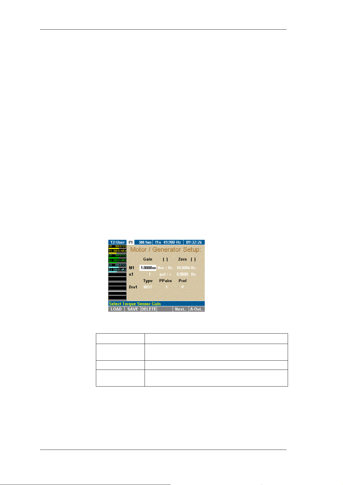
PI1 Process Interface (optional)
Sense of
direction
Call up Motor /
Generator Setup
The sense of direction is detected by means of a permanent signal
(L = sense of direction positive, H = sense of direction negative);
alternatively, it might be determined using an incremental encoder.
In this case, the following applies: if the signal is leading, the sense
of direction is positive; if the signal is lagging, the sense of
direction is negative.
9.3 Configuring PI1
Prior to starting the measuring process, the torque sensor and the
speed sensor must be configured. To configure the process
interface, select menu Motor / Generator Setup. The configuration
procedure consists of the following steps:
- Call up Motor / Generator Setup
- Select motor
- Configure torque sensor
- Configure speed sensor
- Configure other motors
- Configure analog outputs
The device must be equipped with a PI1 process interface.
Menu item PI must be shown in the menu bar
If the analyzer is equipped with a process interface, menu item PI
is shown automatically in the menu.
Move the cursor to menu item PI and press Enter.
Menu Motor / Generator Setup is displayed, showing the
settings for motor 1 (M1).
Adjust the settings as follows:
Line Description
M1
Configure torque measurement (input, slope and
zero) for each motor
n1
Drv1
Configure speed measurement (speed sensor)
Set type (Type), pole pairs (PPairs) and
reference power (Pref)
If you have already saved a configuration that suits the
measuring layout: press function key LOAD, select this
configuration and confirm with Enter.
Adjust configuration as described below.
58 Power Analyzer NORMA 4000, NORMA 5000
EO1111G REV G
Page 61
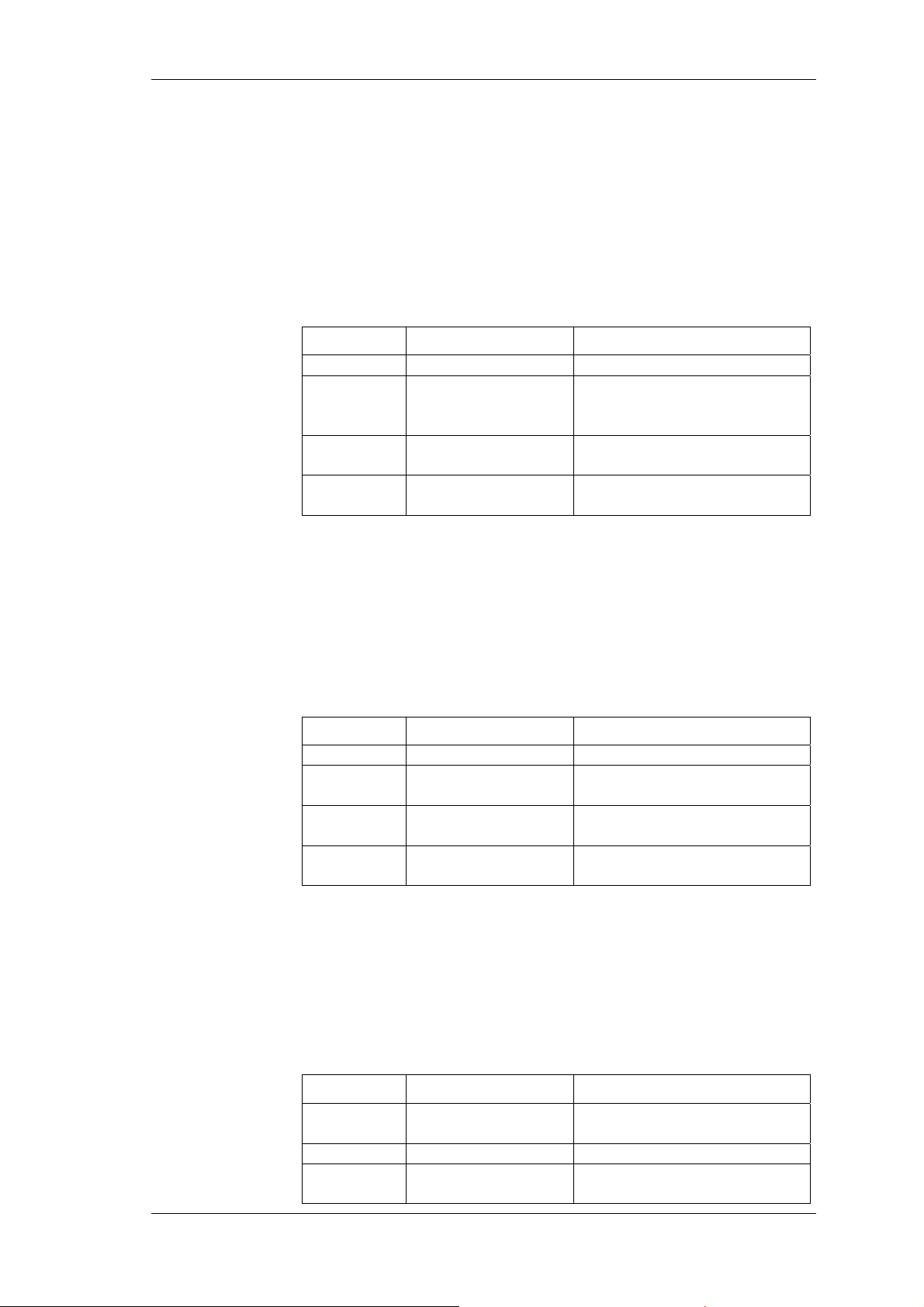
PI1 Process Interface (optional)
Select motor
To configure the system for motor 1, go to "Configure torque
sensor"
– or –
To configure another motor, press Next ... until the
respective motor code (M2, M3 or M4) is displayed.
Configure torque
sensor
The torque can be measured by means of force transducers or a
torque-measuring shaft. The signal is transferred via a ± 10V AC
output or a frequency output. In line M.. (e.g. for motor 1: M1),
adjust the following settings:
Column Settings Description
Gain 1...
Unit
Nm/Hz
Nm/V
Slope
Depending on force
transducer or sensing shaft
type
Zero 1...
Voltage or frequency
corresponding to speed = 0
Unit
Hz, V
Unit for zero, depending on
sensor type
Move the cursor to a field in line M1 and press Enter.
A list of possible options is displayed.
Select a value and confirm with Enter.
The value is now shown in the display field.
Configure speed
sensor
Possible speed sensors are: Incremental encoder (measuring with
TTL / AC output) or an analog signal. In line n.. (e.g. for motor 1:
n1), adjust the settings as follows:
Column Settings Description
Gain 1 ...
Unit
pul/r
rpm/V
Zero 1 ...
Slope
Pulses per revolution
Revolutions per volt
Voltage or frequency
corresponding to speed = 0
Unit
Hz, V
Unit for zero, depending on
sensor type
Move the cursor to a field in line n1 and press Enter.
A list of possible options is displayed.
Select a value and confirm with Enter.
The value is now shown in the display field.
Configure motor
or generator
The analyzer can be used for the analysis of both motors and
generators. To configure the device, adjust the settings in line Drv1
(for motor 1):
Column Settings Description
Type MOT
GEN
PPairs 1 ... 999
Pref P ... P3
Motor
Generator
Number of pole pairs
Reference power for
efficiency calculation
Power Analyzer NORMA 4000, NORMA 5000 59
EO1111G REV G
Page 62
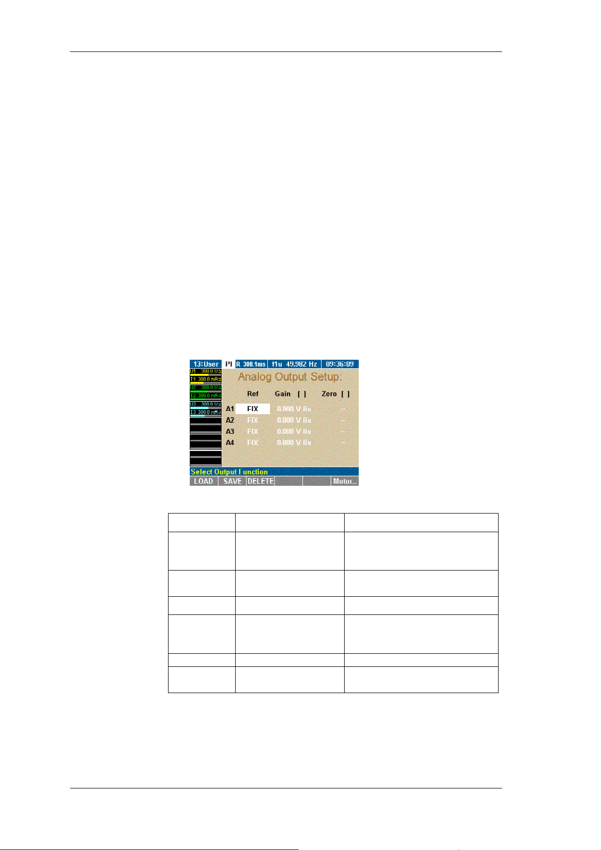
PI1 Process Interface (optional)
Move the cursor to the field in line Drv1 and press Enter.
A list of possible options is displayed.
Select a value and confirm with Enter.
The value is now shown in the display field.
Save the configuration for the motor by pressing SAVE.
Configure other
motors
Press function key Next....
The settings for motor 2 are displayed.
Adjust settings for motors 2 to 4, following the above
instructions for motor 1.
Save the configurations for the motors by pressing SAVE.
Configure analog
output
The 4 analog outputs (A1...A4) can be used to output the measured,
calculated or averaged values or to transfer them to an external
device for further processing. By default, the analog outputs are
configured as voltage output for ±10 V. In order to output higher
voltages, you must enter the relevant transducer ratio, e.g. 10 mV/V
for a measured voltage of 220 V and an output of 2.2 V.
Press function key A-Out.
The Analog Output Setup menu is displayed.
Adjust the settings as follows:
Column Settings Description
Ref FIX
U1, M1, P
M1
...
Fixed DC voltage, or
selection from available
average measured values
Gain 1...
Transducer ratio or fixed
value (-10.3 V to +10.3 V)
Column Settings Description
Unit
Zero 1...
Unit
V/A, V/V, V/Ohm,
V/Hz (depending no
selected Ref)
A, W, V, Hz, Ohm
e.g. 10 mV/V, i.e. 10 mV at
the output correspond to 1 V
of the measured value
Set zero/offset
Unit for zero, depending on
selected Ref
Move the cursor to a field in line A1 and press Enter.
A list of possible options is displayed.
Select a value and confirm with Enter.
The value is now shown in the display field.
Configure analog outputs A2 to A4 accordingly.
60 Power Analyzer NORMA 4000, NORMA 5000
EO1111G REV G
Page 63
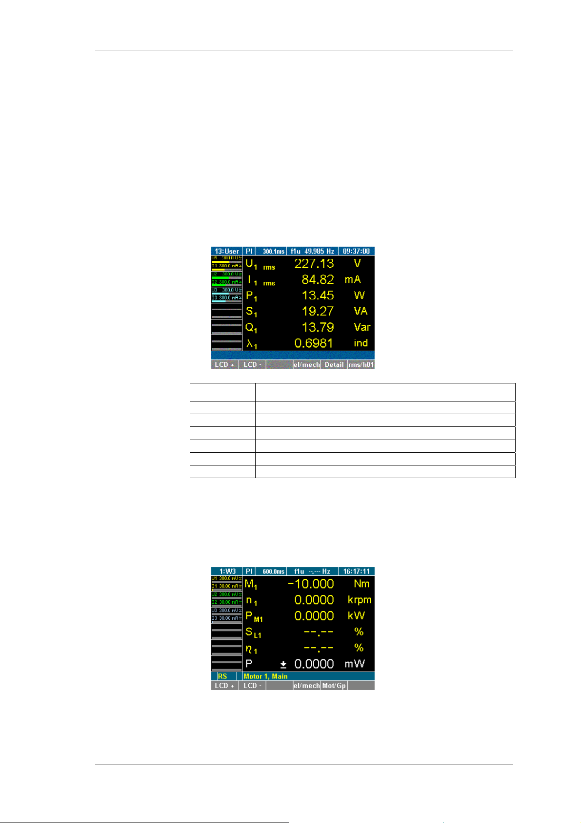
PI1 Process Interface (optional)
V
V
9.4 Measuring with PI1
Torque, rotational speed and mechanical power are measured in
real-time and averaged. They are combined with the measured
electrical values so that slip and mechanical efficiency can be
calculated.
The device must be equipped with a PI1 process interface
Menu item PI must be shown in the menu bar
If the analyzer is equipped with a process interface, menu item PI
is shown automatically in the menu.
Press the measuring key for numerical display.
iew measured
electric values
The measured values of channel 1 are shown.
iew mechanical
values
Display Description
U
1 rms
I
1 rms
P1
S1
Q1
rms voltage value
rms current value
Real power
Apparent power
Idle power
λ1 Power factor
Press measuring keys 1...n to view the values of the respective
channels.
Press function key el/mech.
The measured values of motor 1 are shown.
Press measuring keys 1...n to view the values of the respective
inputs.
Power Analyzer NORMA 4000, NORMA 5000 61
EO1111G REV G
Page 64
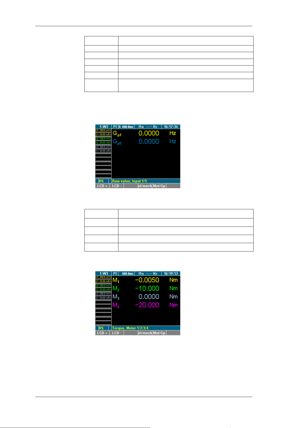
PI1 Process Interface (optional)
V
V
V
Display Description
M1
n1
PM1
SL1
η1
P
Torque of motor 1
Speed of motor 1
Mechanical power of motor 1
Slip of motor 1
Efficiency of motor 1
Electrical reference power, depending on
configuration
iew raw values
Raw values are unscaled values measured in a channel.
Press function key Mot/Gp.
The measured value of motor 1 is shown.
iew all torques
iew all speeds
Press measuring keys 1...n to view the values of the respective
inputs.
Display Description
Gp1
Gp2 ...
Gp5
Gp6 ...
Torque of motor 1
Torque of motor 2
Speed of motor 1
Speed of motor 2
Press measuring key WAV.
The torques of motors 1 to 4 are shown.
Press key WAV again.
The rotational speeds of motors 1 to 4 are shown.
62 Power Analyzer NORMA 4000, NORMA 5000
EO1111G REV G
Page 65
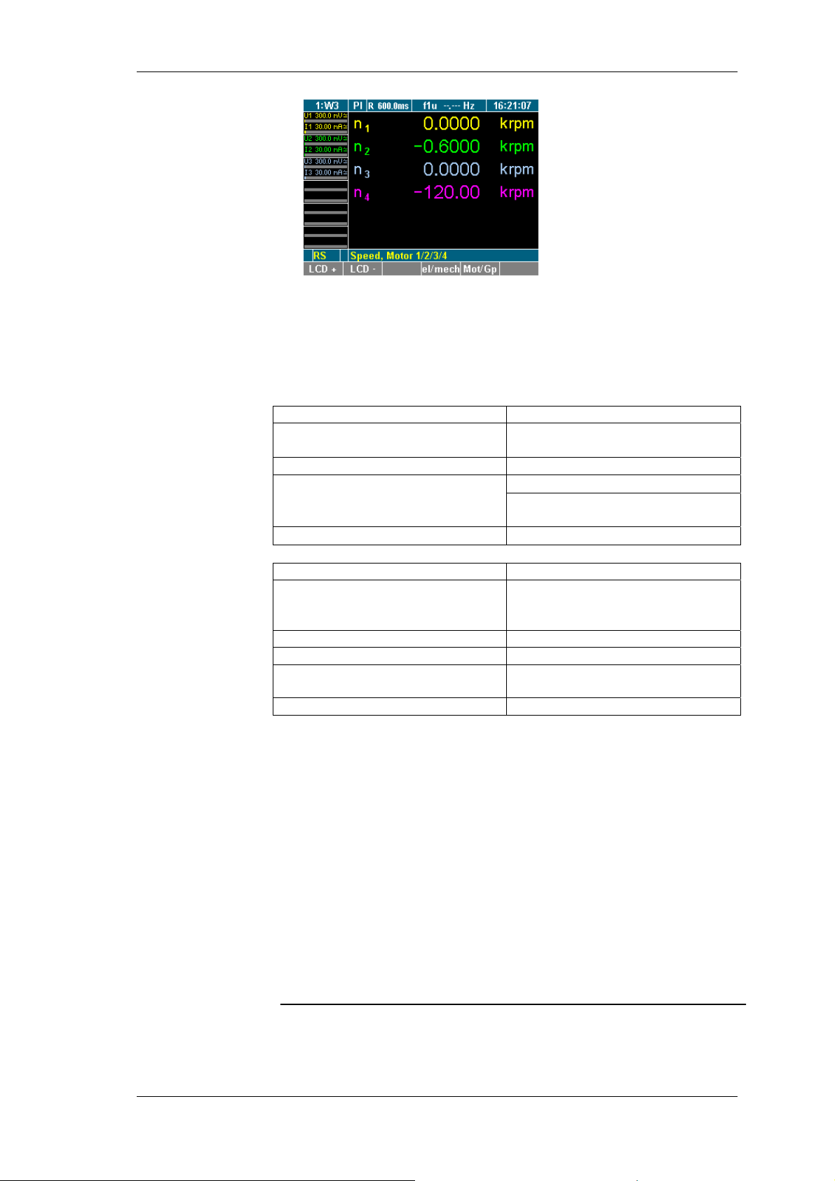
PI1 Process Interface (optional)
9.5 PI1 - technical data
9.5.1 8 inputs (analog/digital)
Each differential input can be configured individually as an analog
or a digital input.
Input configured
as analog input
Input configured
as digital input
Parameter Voltage
Range
±10 V nominal (saturation region
approx. +2 %)
Max. input voltage
Max. common mode voltage to
ground
±50 Vrms
±10 V (without additional error)
±25 V (without limitation by
protective components)
Uncertainty of measurement
±(0.1 % of AVG+ 0.08 % of AVGR)
Parameter Frequency
Measuring signal TTL-compatible or AC (switching
threshold approx. +1.5 V ±0.5 V
hysteresis)
Range 0.5 Hz ... 500 kHz *1
Max. input voltage
Max. common mode voltage to
ground
Uncertainty of measurement
±50 Vrms
±25 V
±0.025 % of AVG
9.5.2 4 digital inputs for the detection of the sense of
rotation
Inputs for the detection of the sense of rotation are only used for
motors and in conjunction with the corresponding digital speed
inputs.
1
The number of pulses per revolution must be synchronised with the rotational
*
speed of the motor in such a way that the maximum measuring frequency is not
exceeded. On the other hand, ensure that the resolution is sufficient to measure
the frequency at low motor speeds.
Power Analyzer NORMA 4000, NORMA 5000 63
EO1111G REV G
Page 66
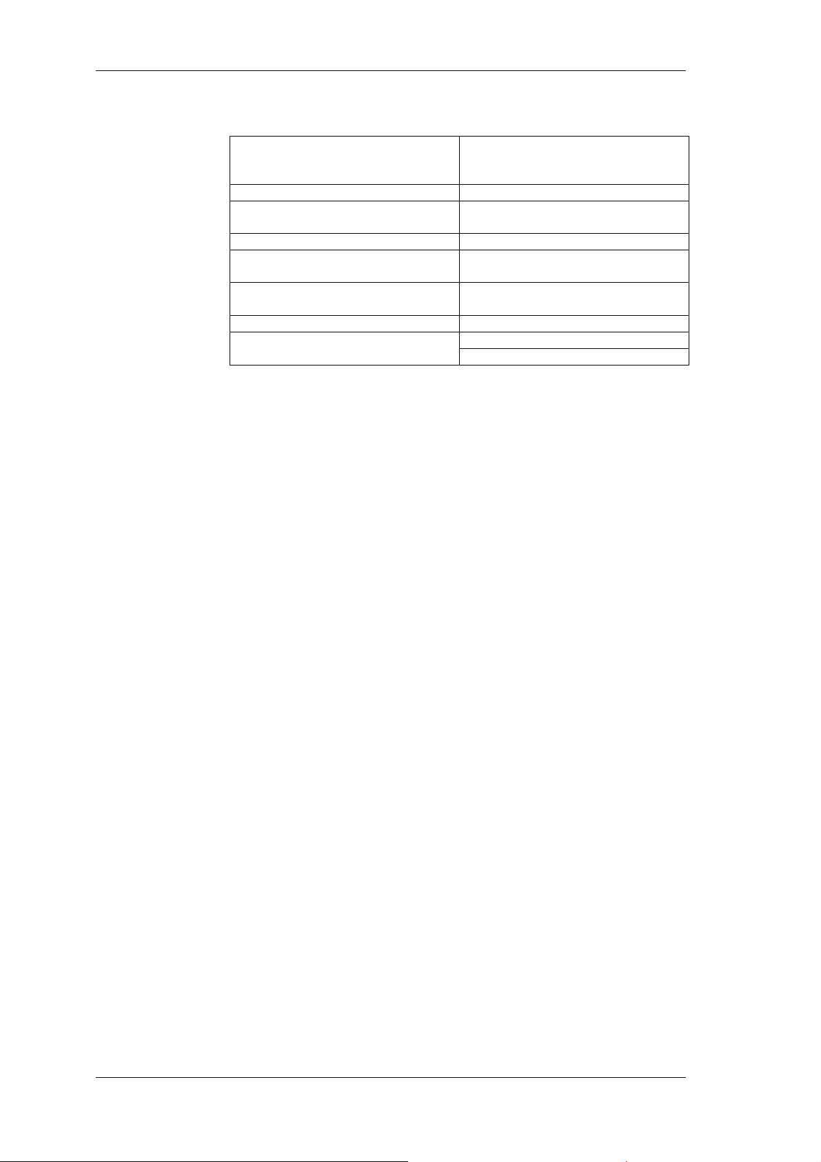
PI1 Process Interface (optional)
9.5.3 4 outputs (analog)
Output voltage max. ± 10.3 V; max. load 5 mA,
Allowable external voltage max. 50 Vrms at HI input
Additional error ± (0.15 % of AVG + 0.05 % of FV),
Temperature coefficient < 0.2 x fault limit/K
Output rate corresponds to current average
Resolution approx. ± 8000 counts for ± 10 V, 1
Rise time 10...90 %: approx. 10 ms
short-circuit protected, shared LO
connection to ground potential
final value FV = 10 V
time
count ≈ 1.25 mV
to ± 0.2 %: 25 ms Response time
to ± 1.0 %: approx. 20 ms
64 Power Analyzer NORMA 4000, NORMA 5000
EO1111G REV G
Page 67

Formulas
π
I
10 Formulas
10.1 Direct current
Resistance:
Power (P):
Arithmetic mean:
RMS value:
Rectified mean
value:
Crest factor:
Form factor:
Rectified mean
value corrected
Active power:
Apparent power:
Reactive power:
Power factor:
Apparent
impedance:
10.2 Alternating current
Typical values for 230-V AC grid (50 Hz):
U
p
U
rms
U
gw
U
U
U
cf =
ff =
P
Z =
IUR =
IUP ⋅=
= 325 V Periodic time t = 0.02 seconds
= 230 V ( = 0.707 * Up
= U
1
=
m
T
=
rms
=
rm
T
U
U
rms
1
T
P
S
S
1
p
T
∫
0
= 207 V ( = 0.637 * Up
rm
T
udt
(pure AC sine = 0)
∫
0
T
U
IUS ⋅=
rms
1
(
T
T
∫
0
rms
U
rm
⋅=
cos
2
)²
dtu
∫
0
//
dtiu
)(
dtu
UUU
)1107,1(
²)²( PSQ −=
(+...inductive, -...capacitive)
g
⋅→=
ϕλ
rmrmrmc
⋅=⋅=
H
01
22
⋅
P
01
H
)(cos
ϕλ
==
S
01
H
Power Analyzer NORMA 4000, NORMA 5000 65
EO1111G REV G
Page 68
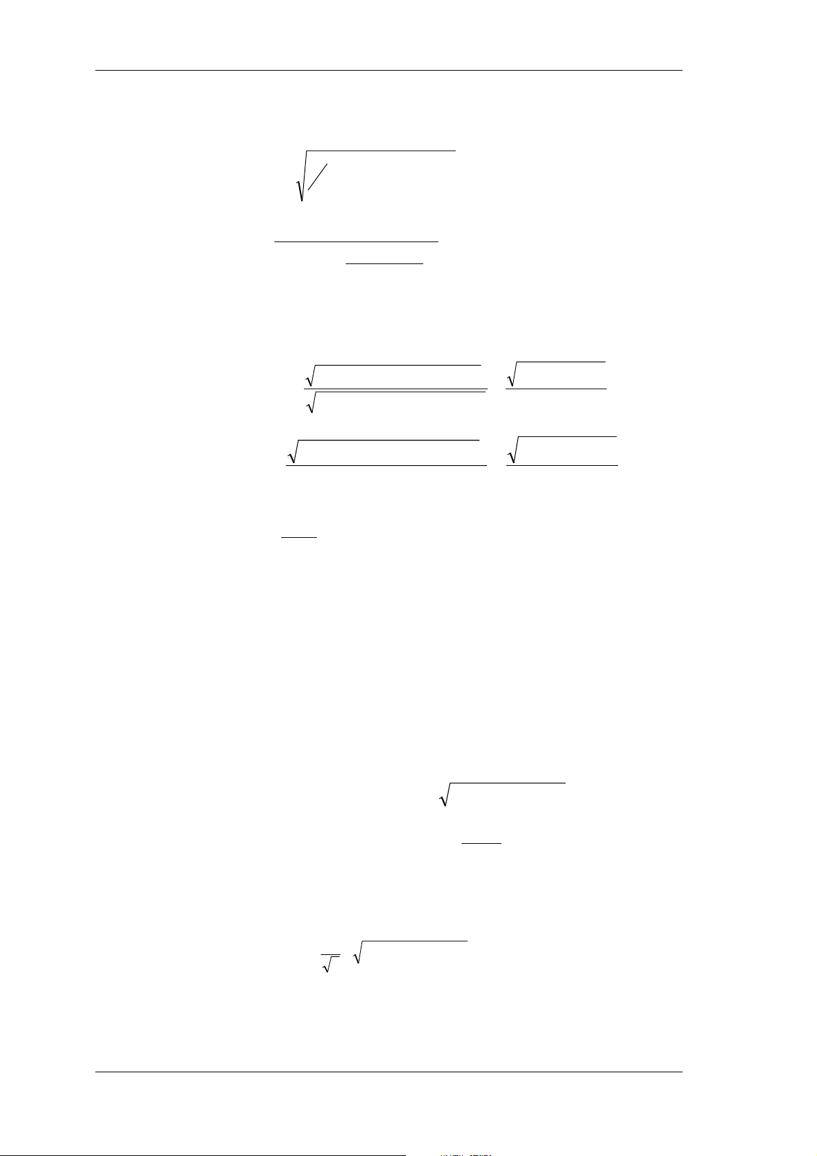
Formulas
=
+
ω
Active energy:
Voltage phase to
phase:
Power corrected:
Harmonic content
(according to DIN):
Harmonic
distortion
(according to IEC):
⋅= dtiuW )(
∫
U
P
=
cx
T
1
∫
T
0
(5,05,0
⋅+
U
−=
P
U
rms
1107,1
⋅
rm
dtUU
)²(
tytxrms
)()(12
x = 1...6
2
)
10.3 Fundamental and harmonics
UUU
)²....²²(
HnHH
=
UUU
²)....²²(
HnHH
)²....²²(
UUU
HnHH
=
U
hc
thd
+++
+++
+++
U
32
21
32
01
H
kU
==
=
U
U
2
−
UU
²
01
Hrms
rms
2
−
H
2
UU
01
Hrms
01
Fundamental
content:
Fourier
transformation:
Uncertainty of
measurement power:
I
fc
I
rms
⇒ fck
1²²
I
H
01
=
10.4 Frequency analysis
∞
∫
0
⋅+⋅=
)]sin()()cos()([)(
ωωωωω
dtStCtF
)(ωC Amplitude of cosine wave
Amplitude of sine wave
)(ωS
The coherence with f(p) results in:
[]
amplitude spectrum:
phase angular:
)()()(
ωωπ
jSCpf −×=
)(
C
ωϕ
)(tan
=
)(
ω
S
10.5 Uncertainty of measurement
M
M
M
Uncertainty of measurement - voltage
U
Uncertainty of measurement - current
I
Uncertainty of measurement - angle
W
2
3
22
2
MMMM ++×=
WIUP
)²)()²(()(
ωωω
SCF +=
66 Power Analyzer NORMA 4000, NORMA 5000
EO1111G REV G
Page 69

Transport and Storage
11 Transport and Storage
11.1 Transport
Transport the device only in its original packaging.
Keep the operating manual supplied with the device for future
reference.
Protect the device during transport against heat and moisture;
do not exceed temperature range of -20 °C to + 50 °C and
max. humidity of 85%.
Protect the device against impacts and loads.
11.2 Storage
Keep original packaging, as it might be required at a later
stage for transport purposes or to return the device for repairs.
Only the original packaging guarantees proper protection
against mechanical impacts.
Store the device in a dry room; the temperature range of -20°C
to + 50 °C and maximum humidity of 85 % may not be
exceeded.
Keep the operating manual supplied with the device for future
reference.
Protect the device against direct sunlight, heat, moisture and
mechanical impacts.
12 Warranty
The warranty period for faultless operation and compliance
with the specified uncertainty of measurement is limited to 2
years from the date of purchase.
Damage due to improper use, overload or operation under
conditions that are outside the range of permitted ambient
conditions are not covered by the warranty.
Warranty covers only technical data that is specified with a
tolerance range. Values or limits for which there are no
tolerances specified are intended for information purposes
only.
13 Recalibration
The manufactorer recommends recalibrating the device every
2 years. The device can be calibrated by the manufactorer
service department or any other calibration specialist.
14 Maintenance
Ensure that the ventilation slots are not blocked. Otherwise,
the device is maintenance-free.
Power Analyzer NORMA 4000, NORMA 5000 67
EO1111G REV G
Page 70

Decommissioning and Disposal
15 Decommissioning and Disposal
15.1 Shutting down
Ensure that all connected devices are switched off and
disconnected from the power supply.
Switch off the power analyzer.
Disconnect the plug from the mains socket.
Remove all connected devices.
Secure the unit against inadvertent switching on.
Ensure that the operating manual is kept near the device.
15.2 Recycling and disposal
Always adhere to the applicable statutory regulations for
recycling and waste disposal.
15.3 Packaging
The following licence agreements have been entered into for
the disposal of the packaging: ARA licence no. 1544 (Austria),
DSD no. 2170305 (Germany).
15.4 Housing
The housing is made in metal and can be recycled.
15.5 Electronic components
The electronic components including the power adapter, filter,
plug-in modules and wires have a weight of approx. 1500 g
and a volume of approx. 3000 cm
3
.
68 Power Analyzer NORMA 4000, NORMA 5000
EO1111G REV G
Page 71
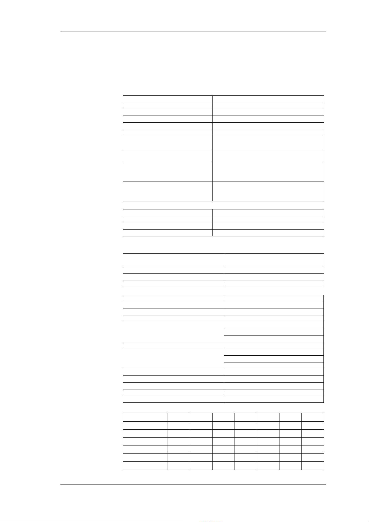
Technical Data
V
16 Technical Data
16.1 Technical data NORMA 4000
General technical data
Compact system With 1 to 3 phases
Continuous averages
Interface Compatible to D5255
Housing Metal housing
Weight approx. 5 kg
Dimensions (W,H,D) 237 mm, 150 mm (3HU), 315 mm
Display 5.7“, 320 x 240 pixel; background
illumination and contrast adjustable
Operation Membrane keyboard, with cursor, function
keys and direct functions
Mains connection 85 ... 264 V AC, 47 ... 440 Hz, DC 120 ...
370 V, approx. 40 VA
Euro plug with switch
Measuring terminals 4 mm guard sockets, 2 each per input; or
screw terminals
external shunt connection via BNC socket
Ambient
conditions
Operating temperature range +5 ... +35 °C
Storage temperature range −20 ... +50 °C
Climatic class B2 (according to IEC 60654-1)
Relative humidity max. 85 %, noncondensing
oltage
Current
Limit of error
Specifications
8 measuring range for U 0.3 – 1 – 3 – 10 – 30 – 100 – 300 –
1000 V
U
peak
Input impedance 2 Mohm // 20 pF
Common mode rejection 120 dB at 100 kHz
2 x measuring range
6 measuring ranges for I direct (10A) 30 – 100 mA – 0.3 – 1 – 3 – 10 A
6 measuring ranges for I direct (20A) 60 – 200 mA – 0.6 – 2 – 6 – 2 A
I
2 x range
peak
Input impedance with integrated shunts (10A)
Ranges
Input impedance with integrated shunts (20A)
Ranges
Measuring connection for shunt or probe
BNC socket 100 kOhm // 30pF
Ranges 30 – 100mV – 0.3 – 1 – 3 – 10 V
Overload max. 20 V
Common mode rejection 120 dB at 100 kHz
Power phase PP30 PP40 PP42 PP50 PP51 PP52 PP54
Limit of error U U U U U U U
reading 0,15% 0,10% 0,10% 0,05% 0,05% 0,05% 0,05%
range 0,15% 0,10% 0,10% 0,05% 0,05% 0,05% 0,05%
Limit of error I I I I I I I
reading 0,15% 0,10% 0,10% 0,05% 0,05% 0,05% 0,05%
range 0,15% 0,10% 0,10% 0,05% 0,05% 0,05% 0,05%
30, 100 mA: 1 ohm
0.3, 1 A: 0.1 ohm
3, 10 A: 0.01 ohm
6, 20 mA: 0.5 ohm
0.6, 2A: 0.05 ohm
6, 2 A: 0.005 ohm
eff
Power Analyzer NORMA 4000, NORMA 5000 69
EO1111G REV G
Page 72
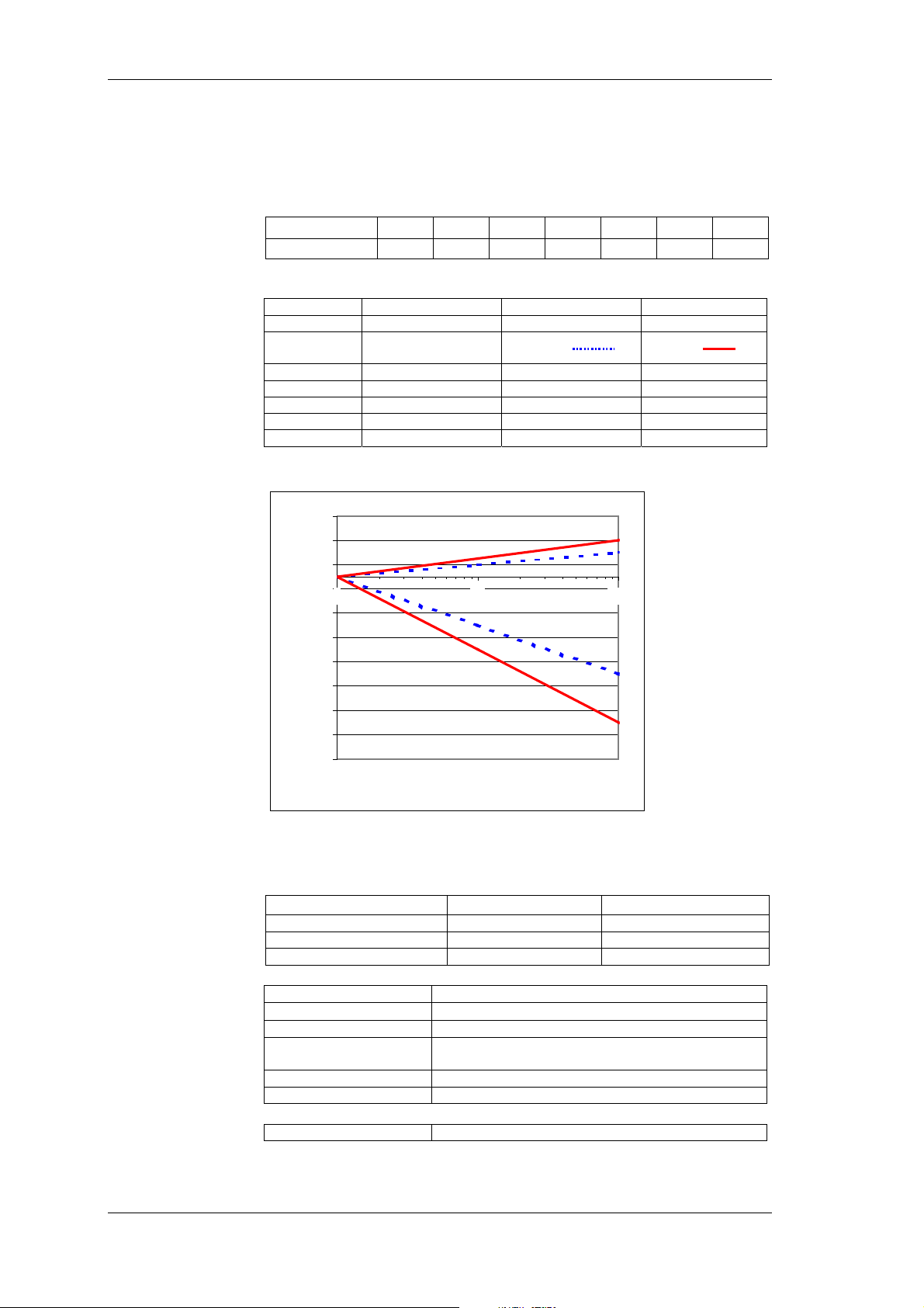
Technical Data
This data is valid for averages and the following reference
conditions:
Ambient temperature 23 +- 0.5 °C, frequency 50 Hz, heat-up
time of minimum 1 hour and incoming measuring signal.
Sample rate
Power Phase PP30 PP40 PP42 PP50 PP51 PP52 PP54
Sample rate 102kHz 341kHz 341kHz 1MHz 1MHz 341kHz 341kHz
Bandwidth
Bandwidth U direct I via BNC I direct measured
PP30 1 MHz 1 MHz 0,3 MHz
PP40 3 MHz 3 MHz 1 MHz
PP42 3 MHz 3 MHz 0,5 MHz
PP50 10 MHz 10 MHz 1 MHz
PP51 3 MHz 3 MHz 1 MHz
PP52 3 MHz 3 MHz 0,5 MHz
PP54 3 MHz 3 MHz 1 MHz
Diagram Bandwidth (limit of error) Power Phase PP40
0,50%
0,30%
0,10%
-0,10%
-0,30%
-0,50%
-0,70%
-0,90%
-1,10%
-1,30%
-1,50%
1 10 100
f[kHz]
For accurate measurements, harmonics over 1 MHz may reach
maximum half of the range.
Angle error
Power phase PP30
Angle error 0,1° + 0,1° /kHz 0,1° + 0,1° /kHz
All other power phases
Angle error 0,005° + 0,005° /kHz 0,025° + 0,015° /kHz
between U and I
between U and I
BNC
direc t
Frequency and
synchronisation
Range 0.2Hz ... Sample rate (102kHz / 341kHz / 1MHz)
Measurement error
Channel selection all channels U/I, or external input
Low-pass filter optionally integratable, with 3 different limit
External Sync-input Max. 50V, 0,2Hz to sample rate
Sync-output Pulsed TTL signal 5V
±0.01% rdg
frequencies
Data memory
Measured data memory approx. 4 MB
70 Power Analyzer NORMA 4000, NORMA 5000
EO1111G REV G
Page 73
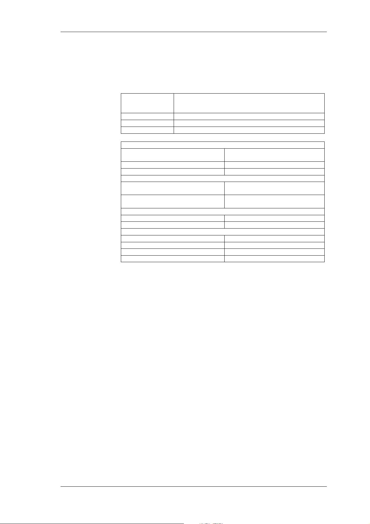
Technical Data
Configuration
memory
The current instrument settings can be stored as configurations in
a non-volatile memory for subsequent reloading. Changes that are
not saved in a configuration are lost when the device is switched
off. Up to 15 user-defined configurations can be permanently
stored under predefined names.
Interfaces
RS 232 RS 232 interface for firmware upload and data exchange
with PC; the device can be connected to a printer through
an external adapter
GPIB IEEE 488.2 / 1 MBit/s
LAN Ethernet / 10 MBits/s or 100 MBits/s
USB USB 2.0
Standards
Electrical safety
EN 61010-1/ 2. edition 1000V CAT II
(600V CAT III)
EN 61558 for transformer
EN 61010-2-031/032 for accessories
Electromagnetic compatibility
Emission IEC 61326-1, EN 50081-1, EN 55011
Immunity IEC 61326-1 / annex A (industrial), EN
Max. input voltage
for voltage inputs Range 1000 V
for current inputs Range 10 A
Test voltages
Mains input housing (earth connector) 1.5 KV a.c.
Mains connection measuring inputs 5.4 kV a.c.
Measuring inputs housing 3.3 kV a.c.
Measuring input measuring input 5.4 kV
Degree of pollution 2,
Protection class I
class B
50082-1
, 2 kV
eff
, 20 A
eff
peak
peak
Power Analyzer NORMA 4000, NORMA 5000 71
EO1111G REV G
Page 74
Technical Data
V
16.2 Technical data NORMA 5000
General technical data
Compact system With 1 to 6 phases
Continuous averages
Interface Compatible to D5255
Housing Metal housing
Weight approx. 7 kg
Dimensions (W,H,D) 447 mm, 150 mm (3HU), 315 mm
Display 5.7“, 320 x 240 pixel; background
Operation Membrane keyboard, with cursor, function
Mains connection 85 ... 264 V AC, 47.. 440Hz, DC 120 ...
Measuring terminals 4 mm guard sockets, 2 each per input; or
Ambient
conditions
Operating temperature range +5 ... +35 °C
Storage temperature range −20 ... +50 °C
Climatic class B2 (according to IEC 60654-1)
Relative humidity max. 85 %, noncondensing
illumination and contrast adjustable
keys and direct functions
370 V, approx. 40 VA
Euro plug with switch
screw terminals
external shunt connection via BNC socket
oltage
Current
Limit of error
Specifications
8 measuring range for U 0.3 – 1 – 3 – 10 – 30 – 100 – 300 –
1000 V
U
peak
Input impedance 2 Mohm // 20 pF
Common mode rejection 120 dB at 100 kHz
2 x measuring range
6 measuring ranges for I direct (10A) 30 – 100 mA – 0.3 – 1 – 3 – 10 A
6 measuring ranges for I direct (20A) 60 – 200 mA – 0.6 – 2 – 6 – 20 A
I
2 x measuring range
peak
Input impedance with integrated shunts (10A)
Ranges
Input impedance with integrated shunts (20A)
Ranges
Measuring connection for shunt or probe
BNC socket 100 kOhm // 30pF
Ranges 30 – 100mV – 0.3 – 1 – 3 – 10 V
Overload (bar) max. 20 V
Common mode rejection 120 dB at 100 kHz
Power phase PP30 PP40 PP42 PP50 PP51 PP52
Limit of error U U U U U U
reading 0,15% 0,10% 0,10% 0,05% 0,05% 0,05%
range 0,15% 0,10% 0,10% 0,05% 0,05% 0,05%
Limit of error I I I I I I
reading 0,15% 0,10% 0,10% 0,05% 0,05% 0,05%
range 0,15% 0,10% 0,10% 0,05% 0,05% 0,05%
30, 100 mA: 1 ohm
0.3, 1 A: 0.1 ohm
3, 10 A: 0.01 ohm
60, 200 mA: 0.5 ohm
0.6, 2 A: 0.05 ohm
6, 20 A: 0.005 ohm
eff
72 Power Analyzer NORMA 4000, NORMA 5000
EO1111G REV G
Page 75
Technical Data
This data is valid for averages and the following reference
conditions:
Ambient temperature 23 +- 0.5 °C, frequency 50 Hz, heat-up
time of minimum 1 hour and incoming measuring signal.
Sample rate
Power Phase PP30 PP40 PP42 PP50 PP51 PP52 PP54
Sample rate 102kHz 341kHz 341kHz 1MHz 1MHz 341kHz 341kHz
Bandwidth
Bandwidth U direct I via BNC I direct measured
PP30 1 MHz 1 MHz 0,3 MHz
PP40 3 MHz 3 MHz 1 MHz
PP42 3 MHz 3 MHz 0,5 MHz
PP50 10 MHz 10 MHz 1 MHz
PP51 3 MHz 3 MHz 1 MHz
PP52 3 MHz 3 MHz 0,5 MHz
PP54 3 MHz 3 MHz 1 MHz
Diagram Bandwidth (limit of error) Power Phase PP50:
0,40%
Angle error
Frequency and
synchronisation
Data memory
0,20%
0,00%
1 10 100 1000
-0,20%
U/I
-0,40%
-0,60%
-0,80%
-1,00%
f[kHz]
BNC
I
direct
For accurate measurements, harmonics over 1 MHz may reach
maximum half of the range.
Power phase PP30
Angle error 0,1° + 0,1° /kHz 0,1° + 0,1° /kHz
All other power phases
Angle error 0,005° + 0,005° /kHz 0,025° + 0,015° /kHz
between U and I
between U and I
BNC
direc t
Range 0.2Hz ... Sample rate (102kHz / 341kHz / 1MHz)
Measurement error
Channel selection all channels U/I, or external input
Low-pass filter optionally integratable, with 3 different limit
External Sync-input Max. 50V, 0,2Hz to sample rate
Sync-output Pulsed TTL signal 5V
±0.01% rdg
frequencies
Measured data memory approx. 4 MB
Power Analyzer NORMA 4000, NORMA 5000 73
EO1111G REV G
Page 76
Technical Data
Configuration
memory
The current instrument settings can be stored as configurations in
a non-volatile memory for subsequent reloading. Changes that are
not saved in a configuration are lost when the device is switched
off. Up to 15 user-defined configurations can be permanently
stored under predefined names.
Interfaces
RS 232 RS 232 interface for firmware upload and data exchange
with PC; the device can be connected to a printer through
an external adapter
GPIB IEEE 488.2 / 1 MBit/s
LAN Ethernet / 10 MBits/s or 100 MBits/s
USB USB2.0
Standards
Electrical safety
EN 61010-1/ 2. edition 1000V CAT II
(600V CAT III)
EN 61558 for transformer
EN 61010-2-031/032 for accessories
Electromagnetic compatibility
Emission IEC 61326-1, EN 50081-1, EN 55011
Immunity IEC 61326-1 / annex A (industrial), EN
Max. input voltage
for voltage inputs Range 1000 V
for current inputs Range 10 A
Test voltages
Mains input housing (earth connector) 1.5 KV a.c.
Mains connection measuring inputs 5.4 kV a.c.
Measuring inputs housing 3.3 kV a.c.
Measuring input measuring input 5.4 kV
Degree of pollution 2,
Protection class I
class B
50082-1
, 2 kV
eff
, 20 A
eff
peak
peak
74 Power Analyzer NORMA 4000, NORMA 5000
EO1111G REV G
Page 77
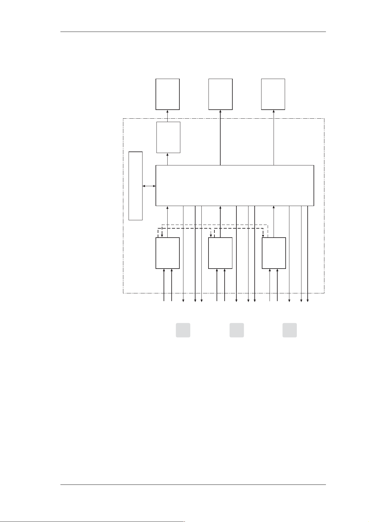
Technical Data
w
16.3 Block diagrams
Overvie
Option: RAM
L12
Display
Graphic
Interface
DSP
Keyboard
m-
Prozessor
L23
DSP
Option:
I/O-Interface
L31
DSP
Logic
Flash-ROM
CLK
U
Settings
I
I
U
Data
L1
I
U
Data
CLK
I
U
SettingsL2Data
I
U
L3
CLK
I
U
Settings
Power Analyzer NORMA 4000, NORMA 5000 75
EO1111G REV G
Page 78
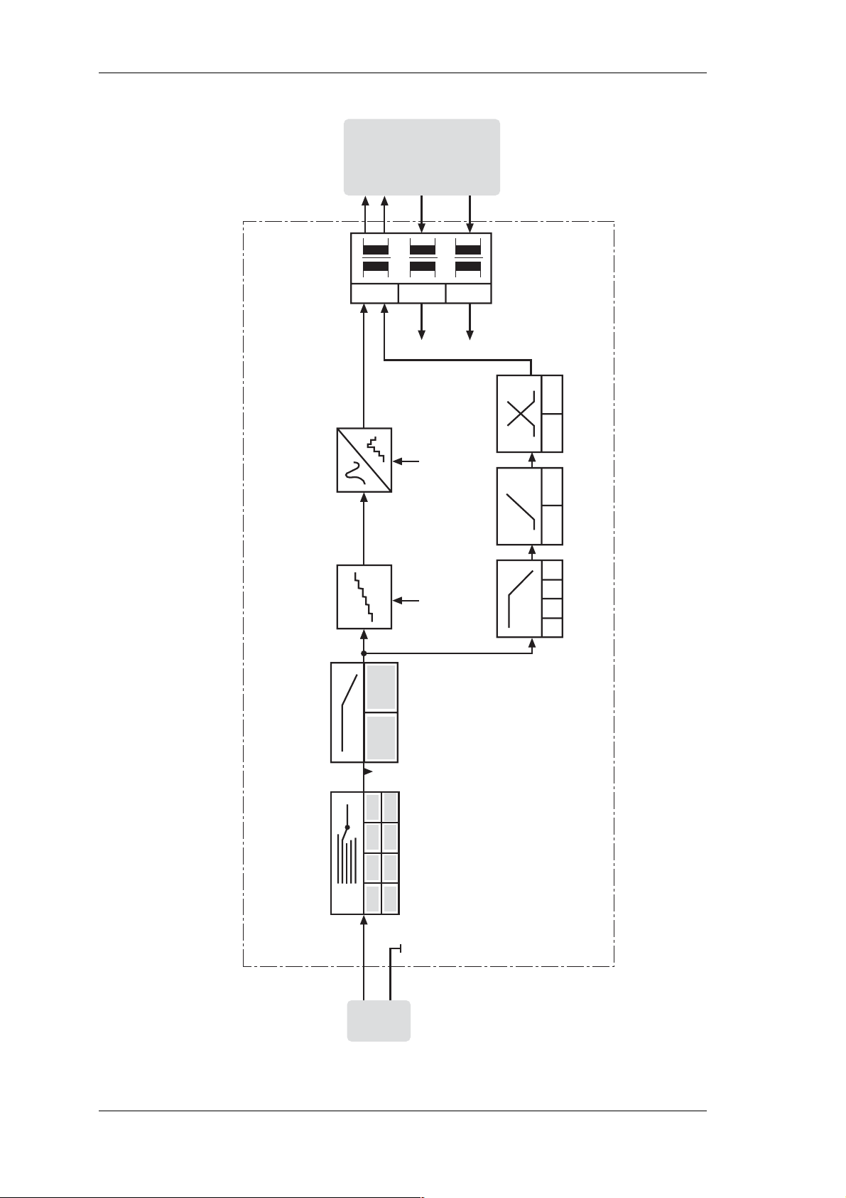
Technical Data
V
oltage channels
Galvanic
separation
Converter
Analog-Digital
Sample/HoldAnti-Aliasing
Data U
CLK
CLK
CLK
CLK
Settings U
Settings
Filter Triggerlevel Slope
off
10
1
100
kHz
kHz
Hz
Filter
Hi
1 V 3 V 10 V0,3 V
offon
100 V 300 V 1000 V30 V
Lo
76 Power Analyzer NORMA 4000, NORMA 5000
EO1111G REV G
Page 79
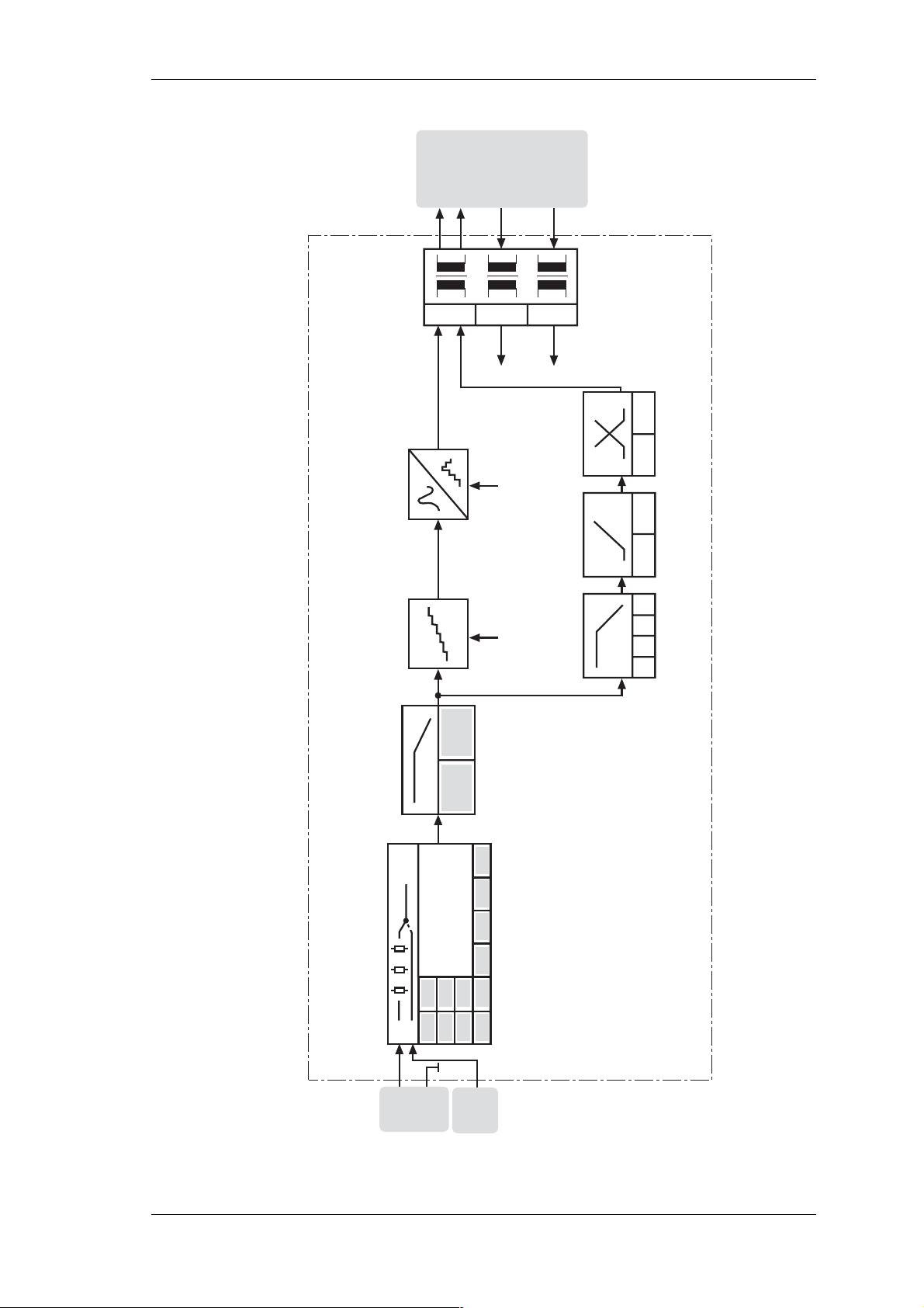
Technical Data
Current channels
Galvanic
separation
Converter
Analog-Digital
Sample/HoldAnti-Aliasing
Data I
CLK
CLK
CLK
CLK
Settings I
Settings
Filter Triggerlevel Slope
off
10
1
100
kHz
kHz
Hz
offon
Filter
1 W ... int. Shunt 1
0,1 W ... int. Shunt 2
0,3 V 1 V 3 V 10 V
0,1 A
0,03 A
Lo
0,01 W ... int. Shunt 3
1 A
10 A
3 A
0,3 A
Ext.
0,03 V 0,1 V
Shunt
Ranges I
Hi
Power Analyzer NORMA 4000, NORMA 5000 77
EO1111G REV G
Page 80
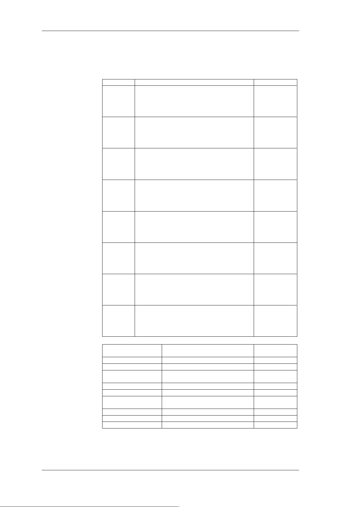
Service and Accessories
17 Service and Accessories
17.1 Instrument
Analyzer
Optional
equipment
Product Description/technical specifications Prod. no.
NORMA
4000
BU 43
NORMA
5000
BU 56
PP 30
PP 40
PP 42
PP 50
PP 52
PP 54
Basic unit 2/3 19“, with power adapter, 5.7"
colour display, back lighted
RS 232 interface for firmware upload,
catering for 3 power phases and optional
extensions
Basic unit 19“, with power adapter, 5.7" colour
display, back lighted
RS 232 interface for firmware upload,
catering for 6 power phases and optional
extensions
Power phase for voltage, current (10A) and
power measurement,
bandwidth 1 MHz, sampling rate 102kHz
limit of error ±0.15% measured value and
±0.15% range
Power phase for voltage, current (10A) and
power measurement,
bandwidth 3 MHz, sampling rate 1/3 MHz
limit of error ±0.1% measured value and ±0.1%
range
Power phase for voltage, current (20A) and
power measurement,
bandwidth 3 MHz, sampling rate 1/3 MHz
limit of error ±0.1% measured value and ±0.1%
range
Power phase for voltage, current (10A) and
power measurement,
bandwidth 10 MHz, sampling rate 1 MHz
limit of error ±0.05% measured value and
±0.05% range
Power phase for voltage, current (20A) and
power measurement,
bandwidth 3 MHz, sampling rate 1/3 MHz
limit of error ±0.05% measured value and
±0.05% range
Power phase for voltage, current (10A) and
power measurement,
bandwidth 3 MHz, sampling rate 1/3 MHz
limit of error ±0.05% measured value and
±0.05% range
Product Description/technical
specifications
IF3 interface USB USB2.0 and Ethernet EA 1001 Z
IF2 interface IEEE488 IEEE 488 and Ethernet EA 1002 Z
PI1 process interface 8 analog/pulse inputs,
4 analog outputs
Internal printer Thermal printer for NORMA 5000 EA 1006 Z
PC printer cable RS-232 Centronics, 1.8 m EA 1007 Z
Additional memory 128 MB additional memory for
NORMA 5000
Rs232 cable 1,5m length 1:1 connected EA 1011Z
LAN cable 2m length, crossed EA 1012Z
USB cable 1,5m length, A to B plug EA 1013Z
EA 1430 Z
EA 1560 Z
EA 1300 Z
EA 1400 Z
EA 1420 Z
EA 1500 Z
EA 1520 Z
EA 1540 Z
Prod. no.
EA 1003 Z
EA 1010 Z
78 Power Analyzer NORMA 4000, NORMA 5000
EO1111G REV G
Page 81
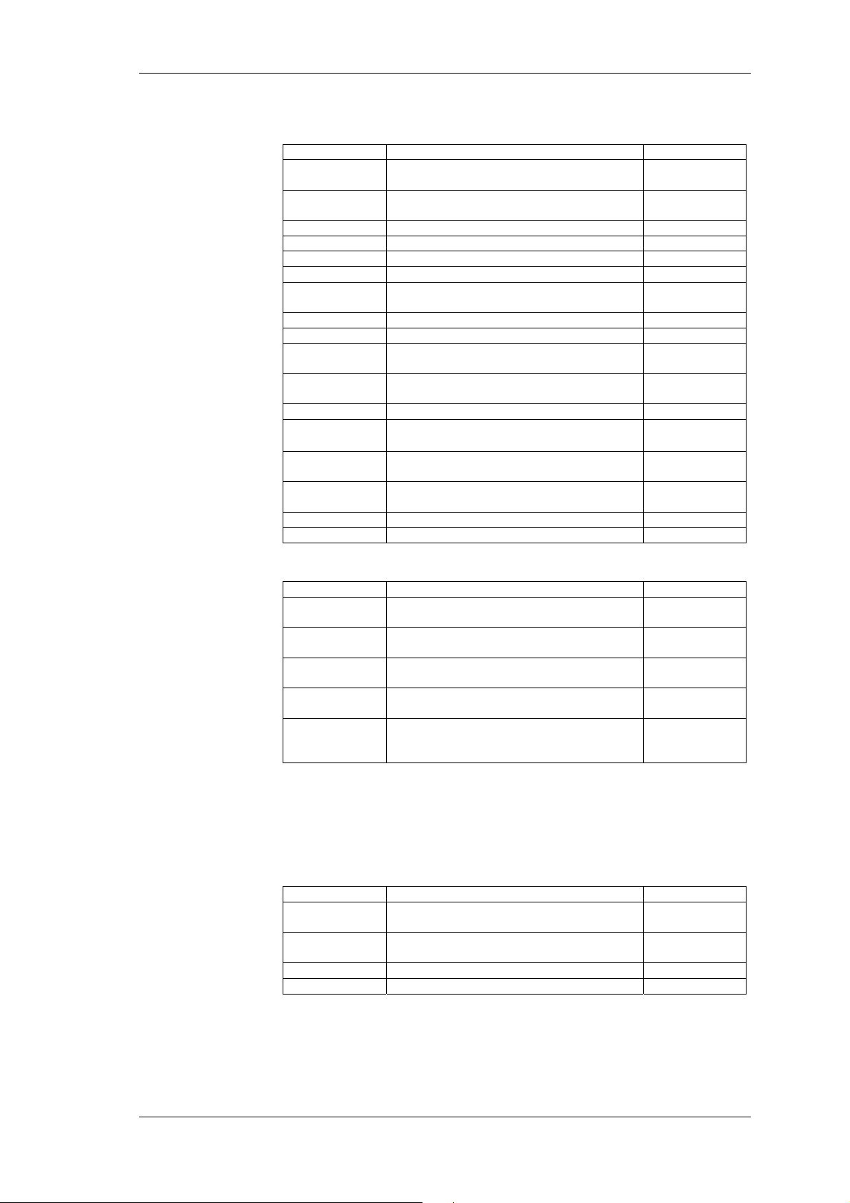
Service and Accessories
17.2 Accessories
Accessories
Software
Product Description/technical specifications Prod. no.
MC1 Measuring lead set for power phase, cable
length 1.5 m
Planar Shunt 32 32 A
10 mohm 0-1 MHz
Shunt 100 Scale 30 A / approx. 30 mV, A641401100
Shunt 300 300 A, 0.2 mohm 0-1 MHz EA 1033 Z
Shunt 1000 1000 A, 0.1 mohm 0-0.5 MHz EA 1034 Z
Shunt 1500 1500 A, 0.1 mohm 0-0.2 MHz EA 1035 Z
Shunt 450 450 A, increased measuring voltage
0.5 mohm 0-0.5 MHz
MCP Measuring lead for planar shunt, 1.5 m EA 1038 Z
MCS Measuring lead for shunt, 1.5 m EA 1039 Z
IT 150-S Transducer 150 A / 0.2 A
DC … 100kHz
IT 600-S Transducer 600 A / 0.4 A
DC ... 100 kHz
LT 3 Power unit for up to 3 IT transducers EA 1047 Z
RR 3030 Lemflex 30/300/3000A with BNC plug
10 Hz-50 kHz
Probe PR1235X Passive probe 1000 / 1 A
30 Hz ... 10 kHz
Probe PR201
ACI
SP 3-phase star point adapter EA 1059 Z
Bag Carrier bag for NORMA 4000 EA 1060 Z
Passive probe 200 / 0,2 A
40 Hz ... 10 kHz
EA 1030 Z
EA 1032 Z
EA 1036 Z
EA 1045 Z
EA 1046 Z
EA 1051 Z
EA 1052 Z
EA 1053Z
Product Description/technical specifications Prod. no.
PowerVIEW
Basic
PowerVIEW
Motor
PowerVIEW
Storage
PowerVIEW
Harmonic
PowerVIEW
Developer
Basic PC software package for numerical
display
Plug-in "Motor" supports the motor
process interface
Plug-in "Storage"
Data memory functions, DSO
Plug-in "Harmonic"
(FFT, Harmonic analysis)
Software package for the design of
customer applications; training and support
are available on request
EA 1090 Z
EA 1091 Z
EA 1092 Z
EA 1093 Z
EA 1094 Z
17.3 Service
General
The power analyzer may only be serviced by specialised
service workshops authorised by LEM Norma.
Service
Power Analyzer NORMA 4000, NORMA 5000 79
EO1111G REV G
Product Description/technical specifications Prod. no.
Cal BU Recalibration of the first power phase of
the analyzer, including LNO test report
Cal PP Recalibration of each of the other power
phases, including LNO test report
Cal 500 Recalibration of a shunt of up to 500A EA 1075 Z
Cal 1500 Recalibration of a shunt of up to 1500A EA 1076 Z
EA 1071 Z
EA 1072 Z
Page 82

Service and Accessories
80 Power Analyzer NORMA 4000, NORMA 5000
EO1111G REV G
Page 83
Printed in Austria / Gedruckt in Österreich / Imprimé en Autriche / Impreso en Austria / Stampato in Austria
LEM NORMA GmbH
Liebermannstraße F01, CAMPUS 21
A-2345 Brunn am Gebirge
AUSTRIA
Tel.: +43(0)2236-691-0
Fax: +43(0)2236-691-415
E-Mail: [email protected]
Internet: www.lem.com
EO1111G REV G
Right to change specification reserved /
Technische Änderungen vorbehalten /
Sous réserve de modifications /
Nos reservamos el derecho a
modificaciones técnicas sin previo aviso /
Tutti i diritti di variazione riservati
Distributor / Vertragshändler / Distributeur / Distribuidor / Distributore
 Loading...