

Page 1

CODE: 277.374
Page 2

The lighting flash with arrowshad symbol within an
equilateral triangle is intended to alert the user to the
presence of uninsulated “dangerous voltages” within the
product’s enclosure, that may be of sufficient magnitude to
constitute a risk of electric schok to persons.
The exclamation point within an equilater triangle is
intended to alert the user to the presence of important
operating and maintenance (servicing) instructions in the
literature accompanyng the appliance.
IMPORTANT SAFETY INSTRUCTIONS
INSTRUCTIONS PERTAINING A RISK OF FIRE, ELECTRIC SHOCK OR INJURY A PERSONS
WARNING - When using electric products, basic precautions should always be followed, including the fol-
lowing.
1. Read all the SAFETY INSTRUCTIONS before using the product.
2. A reduce the risk of injury, close supervision is necessary when the product is used near children.
3. Do not use this product near water - for example, near a bathtub, washbowl, kitchen sink, in a wet base-
ment or near a swimming pool or the like.
4. This product in combination with an amplifier, may be capable of producing sound levels that could cause
permanent hearing loss. Do not operate for a long period of time at high volume level or at level that is
uncomfortable. If you experience any hearing loss or ringing in the ears, you should consult an audiologist.
5. This product should be located so that its location or position does not interfere with its proper ventilation.
6. This product should be located away from heat sources such as radiators, heat register or other product
that produce heat.
/. The product may be connected a power supply only of the type described on the operating instructions or
as marked on the product.
8. The product may be equipped with a polarized line plug (one blade wider then the other). This is a safety
feature. If you are unable a insert the plug into the outlet, contact an electrician a replace your obsolete
outlet. Do not defeat the safety purpose of the plug.
9. The power-supply cord of the product should be unplugged from the outlet when left unused for a long
period of time. When unplugging the power-supply cord, do not pull on the cord, but grasp it by the plug.
10. Care should be taken so that object do not fall and liquid are not spilled into the enclosure through
openings.
11. The product should be serviced by qualified service personnel when:
A. The power-supply cord or the plug has been damaged; or
B. Objects have fallen, or liquid has been spilled into the product; or
C. The product has been exposed to rain; or
D. The product does not appear to operate normally or exhibits a marked change in performance; or
E. The product has been dropped or the enclosure damaged.
12. Do not attempt to service the product beyond that described in the user-maintenance instructions.
All other servicing should be referred to qualified service personnel.
13. WARNING - Do not place objects on the product’s power cord or place it in a position where anyone
could trip over, walk on or roll anything over it. Do not allow the product to rest on or to be installed over
power cords of any type. Improper installations os this type create the possibility of fire hazard and/or personal injury.
SAVE THESE INSTRUCTIONS
Page 3

1
Avvertenze e installazione. . . . . . . . . . . . . . . . . . . . . . . . . . . . . 2
Presentazione . . . . . . . . . . . . . . . . . . . . . . . . . . . . . . . . . . . . . . . 3
Canale di ingresso MONO . . . . . . . . . . . . . . . . . . . . . . . . . . . . . 4
Canale di ingresso STEREO . . . . . . . . . . . . . . . . . . . . . . . . . . . 6
Sezione MASTER . . . . . . . . . . . . . . . . . . . . . . . . . . . . . . . . . . . . 7
DSP. . . . . . . . . . . . . . . . . . . . . . . . . . . . . . . . . . . . . . . . . . . . . . . . 9
Pannello posteriore . . . . . . . . . . . . . . . . . . . . . . . . . . . . . . . . . 10
Cavi di collegamento . . . . . . . . . . . . . . . . . . . . . . . . . . . . . . . . 11
Esempi di collegamento . . . . . . . . . . . . . . . . . . . . . . . . . . . . . 12
Specifiche tecniche . . . . . . . . . . . . . . . . . . . . . . . . . . . . . . . . . 14
Indice
Indice
Page 4
2
Avvertenze e installazione
✔ ✔
✔ ✔
✔ Collegamento alla rete - Accensione e spegnimento
Prima di collegare il mixer alla presa di corrente accertatevi sempre che:
- l’impianto elettrico e la presa della corrente dispongano di un’appropriata messa
a terra compatibile con le norme di sicurezza (in caso di incertezza consultate
personale specializzato);
- l a tensione di rete corrisponda a quella indicata sul retro dell’apparato (è accettata una
tolleranza fino a ±10%);
- il cavo di alimentazione non sia danneggiato e non presenti fili scoperti;
- il pulsante di accensione sia in posizione OFF (spento).
Assicuratevi che il mixer sia spento anche prima di scollegare il cavo di alimentazione dalla presa della
corrente.
Al momento dell’accensione o dello spegnimento accertatevi che il volume di uscita sia chiuso:
in questo modo eviterete fastidiosi e talvolta dannosi picchi di segnale.
✔ ✔
✔ ✔
✔ Collegamento e prevenzione o individuazione di disturbi
Verificate, innanzitutto, che il luogo di installazione non presenti disturbi industriali o a radio frequenza.
Evitate comunque di installare la vostra apparecchiatura in stretta prossimità di apparecchi radio, TV,
telefoni cellulari, etc., in quanto questi potrebbero causare interferenze rumorose.
Collegando gli altri apparati del vostro impianto audio, ponete molta attenzione ai cosiddetti “loop di massa”
che potrebbero causare ronzii o interferire con le ottime prestazioni di rapporto Segnale/Rumore e di
bassa distorsione del prodotto. Il metodo migliore (anche se non sempre praticabile) per prevenire loop
di massa consiste nel collegare le masse elettriche di tutti gli apparati ad un solo punto centrale (sistema
“a stella”). In un sistema audio, il punto centrale a cui collegarsi può essere considerato il mixer.
✔ ✔
✔ ✔
✔ Protezione e manutenzione
Non forzate manopole, interruttori e cursori: sono studiati per rispondere ad una leggera pressione e
potrebbero essere danneggiati se usati con forza eccessiva.
Abbiate cura dei cavi di collegamento, fonti di frequentissimi piccoli-grandi guai. Afferrateli sempre per i
connettori, evitate di tirarli con forza ed avvolgeteli evitando nodi o forti torsioni: ne allungherete la vita e
l’affidabilità, a vostro assoluto vantaggio.
Evitate di esporre l’apparato alla irradiazione solare diretta, a forti fonti di calore, ad intense vibrazioni,
ad ambienti molto polverosi o particolarmente umidi o, peggio ancora, alla pioggia: eviterete possibili
malfunzionamenti, deterioramenti o addirittura shock elettrici ed incendi. L’apparato è realizzato in
materiale antiurto. In ogni caso, proteggetene il trasporto per prevenirne gli incidenti del caso.
A fine uso è sempre consigliabile proteggere l’apparato dalla polvere. In ogni caso, l’eventuale deposito
di polvere può essere rimosso usando “a secco” un panno morbido o un pennello.
Non usate mai alcool,
acetone o solventi vari. L’apparato non ha bisogno di ulteriori manutenzioni.
✔ ✔
✔ ✔
✔ In caso di avaria
Tutte le regolazioni sono esterne ed accessibili alla vostra portata. In caso di avaria non aprite l’apparato,
ma rivolgetevi al più vicino Centro di Assistenza Generalmusic/Lem.
✔ ✔
✔ ✔
✔ Conservazione della documentazione
Conservate questo manuale d’uso per eventuali future consultazioni. Ricordate, inoltre, che sul mercato
dell’usato un prodotto ottiene sempre una migliore valutazione se, oltre ad essere ben conservato, è
corredato dalla documentazione e dell’imballo originali.
Avvertenze e installazione
Page 5
3
Presentazione
Congratulazioni per l’acquisto di MX8P FX!
POST
AUX
POST
AUX
POST
AUX
POST
AUX
POST
AUX
POST
AUX
MIX
TAPE
SIGNAL
PEAK
RL
TAPE IN
LEVEL
MIX
PHONO PHONO
LINE LINE
LEFT LEFT
RIGHT RIGHT
-5dB -5dB -5dB -5dB
-55dB -55dB -55dB -55dB
LEFT LEFT LEFT LEFT LEFT LEFT
+15 +15 +15 +15
+15 +15 +15 +15
+15 +15 +15 +15
-15 -15 -15 -15
-15 -15 -15 -15
-15 -15 -15 -15
10
MIC
LINE
MIC
LINE
MIC
LINE
MIC
LINE
STEREO
LINE
STEREO
LINE
10 10 10 10 10
10 10 10 10 10 10
000000
000000
RIGHT RIGHT RIGHT RIGHT RIGHT RIGHT
2.5kHz 2.5kHz 2.5kHz 2.5kHz
LEVEL LEVEL LEVEL LEVEL LEVEL LEVEL
PAN PAN PAN PAN BAL BAL
80Hz 80Hz 80Hz 80Hz
LOW LOW LO W LOW
MID MID MID MID
12 kHz 12 kHz 12 kHz 12 kHz
HIGH HIGH HIGH HIGH
GAIN GAIN GAIN GAIN
-5dB
-55dB
GAIN
-5dB
-55dB
GAIN
1 2 3 4 5/6 7/8
MON
AMP
PHONES/
+20
+20
MAX
MAX
TAPE OUT
TAPE IN
L
R
POWER
ON
PHANTOM
+48V
LINE LINE LINE LINE
MIC MIC MIC MIC
1
2
3
4
MIX OUT
AUX
RETURN
L
L/MONO
R
R
HEADPHONES
AUX OUT
DSP
DSP RETURN
AUX RETURN
MUTE
VOC2
VOC1
PERC
PLATE
S/ROOM
DEL2
DEL1
VOC3
CHURCH
DEL5
DEL4
DEL3
M/HALL
L/HALL
L/ROOM
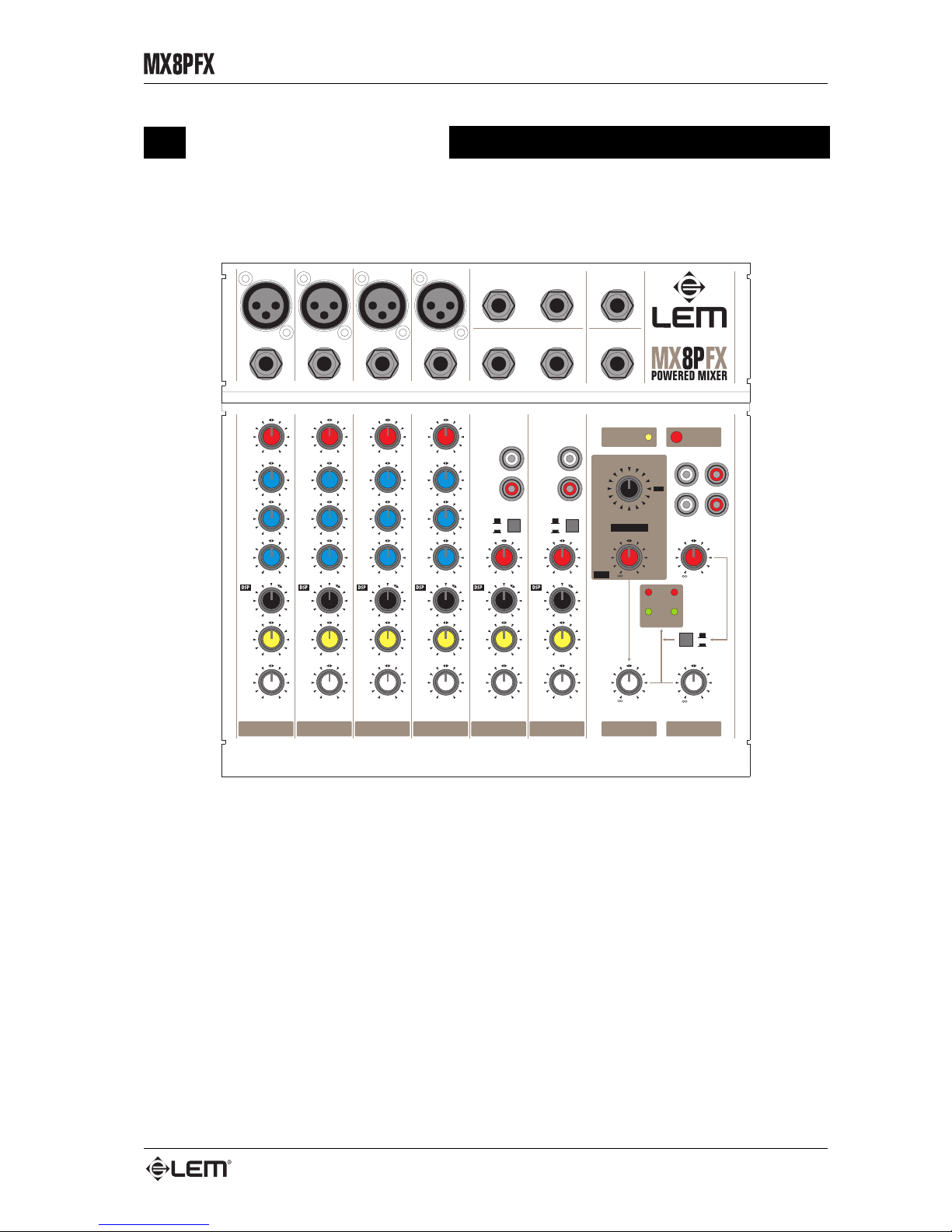
MX8P FX è un mixer amplificato compatto ed estremamente versatile, in grado di offrire
un alto numero di funzioni in uno spazio molto contenuto. Dotato di un robusto amplificatore
interno e di un effetto digitale di elevata qualità, MX8P FX è realizzato in modo da facilitare al
massimo tutte le operazioni di trasporto, installazione ed utilizzo e rappresenta la soluzione ideale
per chi necessita, per il proprio lavoro o per il proprio divertimento, di un mixer amplificato pratico,
affidabile e con una ottima qualità sonora.
MX8P FX è dotato di 4 canali MONO microfonici e 2 canali STEREO di linea ed offre
una serie di funzioni in grado di soddisfare facilmente le più svariate esigenze di mixaggio: dai
piccoli gruppi musicali ai musicisti MIDI, dalle installazioni fisse ai sistemi di amplificazione da
trasporto. Il DSP interno dispone di 15 effetti di RIVERBERO e STEREO DELAY di ottima
qualità, in grado di riprodurre con grande fedeltà diversi tipi di ambiente e di arricchire non solo
la voce, ma qualunque tipo di strumento. La presenza di un amplificatori integrato da 50+50
WATTS estremamente compatto e leggero lo rende un sistema integrato molto efficiente e, allo
stesso tempo, caratterizzato da una estrema semplicità d’uso.
Presentazione
Page 6
4
Canale di ingresso MONO
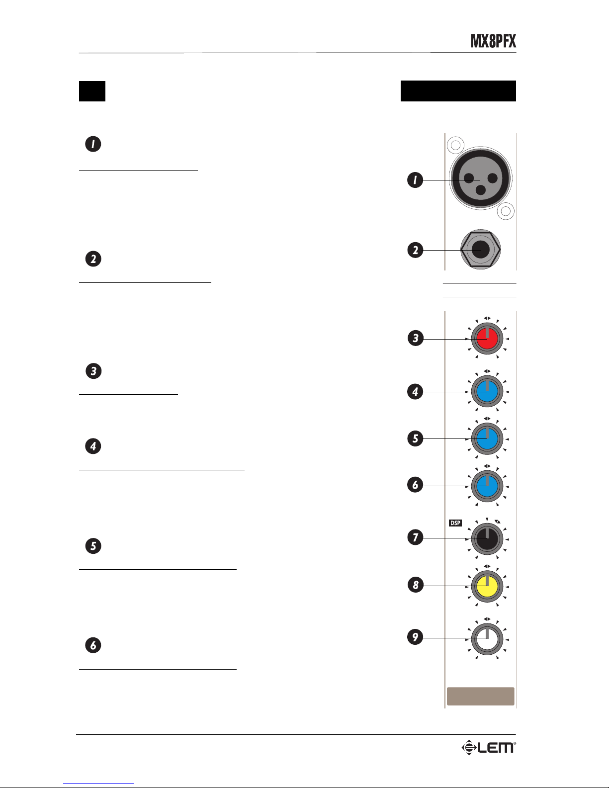
MIC INPUT
Connettore XLR bilanciato: riceve il segnale microfonico in ingresso.
Questo ingresso, riservato all'utilizzo di microfoni, può ricevere una vasta
gamma di segnali bilanciati o sbilanciati a bassa impedenza.
Non collegate a questo ingresso tastiere, registratori od altre
apparecchiature con segnale di linea, poiché il segnale risulterebbe di
livello eccessivo e probabilmente distorto.
LINE INPUT
Connettore JACK sbilanciato: riceve il segnale di linea in ingresso.
Questo ingresso può ricevere segnali di linea provenienti da
apparecchiature con uscita ad alto livello (tutti gli strumenti eccetto i
microfoni).
Non collegate microfoni a questo ingresso, poiché il segnale risulterebbe
di basso livello e probabilmente di scarsa qualità.
GAIN
Controllo di guadagno: regola l'amplificazione del segnale proveniente
dall'esterno verso il canale e permette di determinare un suono
“presente” e prevenire la distorsione del segnale.
HIGH
Controllo per le frequenze ALTE: consente un guadagno o
un’attenuazione di 15 dB a 12 kHz con una curva di tipo
“SHELVING”. Se volete ottenere un suono più “frizzante” o più “chiaro”
ruotate il potenziometro verso destra (+15). Se, invece, siete infastiditi
da un suono troppo acuto allora ruotatelo verso sinistra (-15).
MID
Controllo per le frequenze BASSE: consente un guadagno o una
attenuazione di 15 dB a 2.5 kHz con una curva di tipo “PEAKING”.
Se volete ottenere un suono più “presente” ruotate il potenziometro
verso destra (+15). Se, invece, siete infastiditi da un suono troppo
“metallico” allora ruotatelo verso sinistra (-15).
LOW
Controllo per le frequenze BASSE: consente un guadagno o una
attenuazione di 15 dB a 70 Hz con una curva di tipo “SHELVING”.
Se volete ottenere un suono più “corposo” ruotate il potenziometro verso
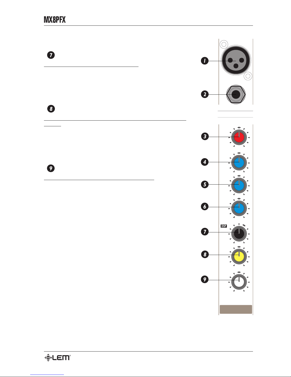
destra (+15). Se, invece, siete infastiditi da un suono troppo “pieno”
Canale di ingresso MONO
POST
AUX
-5dB
-55dB
LEFT
+15
+15
+15
-15
-15
-15
10
MIC
LINE
10
0
0
RIGHT
2.5kHz
LEVEL
PAN
80Hz
LOW
MID
12 kHz
HIGH
GAIN
1
LINE
MIC
1
Page 7
5
Canale di ingresso MONO
allora ruotatelo verso sinistra (-15).
DSP / AUX
Controllo di livello della mandata DSP / AUX.
Invia il segnale contemporaneamente al DSP interno e all’uscita AUX
OUT, consentendo, eventualmente, anche l’utilizzo di un effetto esterno
La mandata DSP / AUX è posizionata POST–FADER e, quindi, preleva
il segnale dopo il controllo di livello del canale. Per questo motivo, è
riservata principalmente all’utilizzo di effetti.
PAN
Potenziometro a scatto centrale per il controllo panoramico del
segnale: regola la “posizione” stereofonica del segnale rispetto alle
uscite principali MIX L&R. Se il PAN viene ruotato completamente verso
SINISTRA (LEFT), il segnale sarà inviato solo al MIX LEFT, se invece
viene ruotato completamente verso DESTRA (RIGHT), il segnale sarà
inviato solo al MIX RIGHT. Nelle posizioni intermedie, il segnale viene
inviato verso entrambe le destinazioni, in proporzioni diverse.
LEVEL
Potenziometro per il controllo del livello del canale: regola il livello
di ciascun canale verso le uscite principali MIX L&R.
POST
AUX
-5dB
-55dB
LEFT
+15
+15
+15
-15
-15
-15
10
MIC
LINE
10
0
0
RIGHT
2.5kHz
LEVEL
PAN
80Hz
LOW
MID
12 kHz
HIGH
GAIN
1
LINE
MIC
1
Page 8
6
POST
AUX
PHONO
LINE
LEFT
RIGHT
LEFT
STEREO
LINE
10
10
0
0
RIGHT
LEVEL
BAL
-5dB
-55dB
GAIN
7/8
Canale di ingresso STEREO
Canale di ingresso STEREO
STEREO INPUT
Connettori RCA: ricevono il segnale STEREO di linea in ingresso.
A seconda della posizione del SELETTORE DI INGRESSO, è possibile
collegare segnali di linea provenienti da apparecchiature con uscita ad
alto livello (LINE) oppure segnali con equalizzazione RIIA provenienti
da giradischi (PHONO).
LINE/PHONO
Selettore di ingresso del canale: consente di selezionare il tipo di
segnale in ingresso e cioè:
• pulsante sollevato = segnale di linea;
• pulsante premuto = segnale phono.
GAIN
Controllo di guadagno: regola l'amplificazione del segnale proveniente
dall'esterno verso il canale e permette di determinare un suono
“presente” e prevenire la distorsione del segnale.
DSP / AUX
Controllo di livello della mandata DSP / AUX.
Invia il segnale contemporaneamente al DSP interno e all’uscita AUX
OUT, consentendo, eventualmente, anche l’utilizzo di un effetto esterno
La mandata DSP / AUX è posizionata POST–FADER e, quindi, preleva
il segnale dopo il controllo di livello del canale. Per questo motivo, è
riservata principalmente all’utilizzo di efffetti.
BAL
Controllo di bilanciamento del segnale sulle uscite principali.
Il controllo BAL effettua un bilanciamento tra i livelli di le due componenti LEFT e RIGHT del segnale
STEREO e agisce nel seguente modo:
• ruotando il BAL verso SINISTRA (LEFT) si ha una riduzione del livello del segnale RIGHT sul MIX RIGHT;
• ruotando il BAL verso DESTRA (RIGHT) si ha una riduzione del livello del segnale LEFT sul MIX LEFT.
LEVEL
Potenziometro per il controllo del livello del canale: regola il livello di ciascun canale verso le uscite
principali MIX L&R.
Page 9
7
Sezione MASTER
Sezione MASTER
AUX OUT
Connettori JACK sbilanciati: questi
connettori inviano verso l’esterno la
somma dei segnali provenienti dalle
corrispondenti mandate DSP / AUX
dei canali di ingresso. La mandata
DSP / AUX è POST–FADER e,
quindi, prevista principalmente per
l’utilizzo di effetti.
AUX IN L&R
Connettori JACK sbilanciati: sono
i connettori dell’ingresso stereo
ausiliario disponibile nell’MX8P FX.
Questo ingresso, il cui segnale viene inviato
direttamente al MIX L&R, può essere utilizzato
per il ritorno del segnale da effetti esterni oppure
per collegare qualunque strumento o apparato
con uscite di linea (ad esempio una tastiera, un
registratore a cassette o un lettore CD).
DSP / AUX RETURN
Potenziometro per il controllo del livello
dell’ingresso stereo ausiliario e del livello
dell’EFFETTO INTERNO (vedi paragrafo
DSP).
MIX L&R OUT
Due connettori JACK bilanciati: sono i
connettori delle uscite di linea principali del
mixer, che inviano all’esterno il programma
proveniente dal MIX L&R.
MIX
Potenziometro per il controllo del volume
generale: controlla il livello dei segnali
provenienti dai canali di ingresso verso le uscite
principali MIX OUT L&R, verso l’uscita TAPE
OUT e verso gli ingressi dell’amplificatore
interno.
MIX
TAPE
SIGNAL
PEAK
RL
TAPE IN
LEVEL
MIX
MON
AMP
PHONES/
+20
+20
MAX
MAX
TAPE OUT
TAPE IN
L
R
POWER
ON
PHANTOM
+48V
DSP
DSP RETURN
AUX RETURN
MUTE
VOC2
VOC1
PERC
PLATE
S/ROOM
DEL2
DEL1
VOC3
CHURCH
DEL5
DEL4
DEL3
M/HALL
L/HALL
L/ROOM
MIX OUT
AUX
RETURN
L
L/MONO
R
R
HEADPHONES
AUX OUT
Page 10
8
PHONES OUT
Connettore JACK STEREO per l’uscita di cuffia: collegate a questa uscita solo cuffie stereo con
impedenza minima di 220 Ohms. E, possibile collegare questa uscita anche all’ingresso di un amplificatore
per l’ascolto in monitor.
PHONES LEVEL
Controllo di livello dell’uscita di cuffia.
TAPE OUT L&R
Due connettori RCA: inviano verso l’esterno il segnale prelevato dal MIX e destinato, in genere, alla
registrazione STEREO. Potete collegare queste uscite agli ingressi del registratore.
TAPE IN L&R
Due connettori RCA: ricevono dall’esterno il segnale di registratori STEREO, CD player, DAT, ecc. Potete
collegate questi ingressi alle uscite delle vostre apparecchiature.
TAPE IN
Controllo di livello dell’ingresso TAPE IN: regola il livello del segnale proveniente da un registratore
esterno verso le uscite MIX L&R. Durante le registrazioni regolate il controllo TAPE IN sulla posizione
“0” (chiuso) per evitare fastidiosi e “pericolosi” ricicli o loops di segnale.
MIX/TAPE
Selettore per l’assegnazione del segnale del TAPE IN all’uscita MIX:
• tasto sollevato (MIX) = il segnale del TAPE IN viene inviato solo all’uscita di cuffia;
• tasto premuto (TAPE) = il segnale del TAPE IN viene inviato anche all’uscita MIX.
LEVEL
LEDs di visualizzazione del livello del segnale MIX L&R.
I LEDs sono di 2 diversi colori:
• verde/SIGNAL = indicano il normale livello operativo del segnale;
• rosso/PEAK = indicano la presenza di segnale ad un livello troppo elevato (OVERLOAD).
Per garantirvi segnali puliti e non distorti ed anche per evitare di danneggiare i componenti del vostro
impianto cercate di prevenire l’accensione continuata dei LEDs di colore rosso.
+48V
LED di segnalazione dell’accensione della alimentazione phantom +48 Volt.
Questo LED si illumina quando viene azionato il tasto di accensione situato sul pannello connettori nel
retro del mixer.
ON
LED di segnalazione dell’accensione del mixer.
Sezione MASTER
Page 11
9
DSP
DSP
+20
DSP
DSP RETURN
AUX RETURN
MUTE
VOC2
VOC1
PERC
PLATE
S/ROOM
DEL2
DEL1
VOC3
CHURCH
DEL5
DEL4
DEL3
M/HALL
L/HALL
L/ROOM
Il mixer MX8P FX è equipaggiato con DSP interno che
dispone di 15 effetti di RIVERBERO e STEREO
DELAY di ottima qualità, in grado di riprodurre con
grande fedeltà diversi tipi di ambiente e di arricchire non
solo la voce, ma qualunque tipo di strumento.
La selezione dei 15 PRESETS disponibli avviene tramite
un comodo selettore a 16 posizioni. Nell’ultima posizione
è collocato un PRESET MUTE che può essere utilizzato
per l’esclusione rapida dell’effetto su tutti i canali.
Il segnale viene inviato all’effetto interno tramite la
mandata DSP / AUX dei canali di ingresso. La quantità
di segnale trattato inviata alle uscite MIX viene
controllata dal potenziometro DSP RETURN.
NOTA: nel caso si desideri utilizzare un effetto interno collegato
all’uscita AUX OUT e agli ingressi AUX RETURN, l’effetto interno
può essere escluso selezionando il PRESET MUTE. Il DSP interno
e l’effetto esterno possono essere utilizzati anche
contemporaneamente, ma tale condizione non è consigliabile.
Di seguito è riportata una tabella con l’elenco ed i
parametri principali dei 15 PRESETS di effetto disponibili
nel DSP interno.
No. PRESET Effetto REV TIME (s)
1 CATHEDRAL HALL REVERB 5.0
2 LARGE HAL L HALL REVERB 3.0
3 MID HALL HAL L REVE RB 1.7
4LARGE ROOMROOM REV ERB 1.5
5 SMALL ROOM ROOM REVE RB 0.8
6PLATE PLATE REVERB 1.5
7PERCUSSIONPLATE REVERB 1.2
8VOCAL 1 PLATE REVERB 3.0
9VOCAL 2 PLATE REVERB 1.5
10 VOCAL 3 PLATE REVERB 0.9
No. PRESET Effett o DELAY LEFT (ms) DELAY RIGHT (ms) FB LEFT (%) FB RIGHT (%)
11 DELAY 1 ST EREO DELA Y 100 200 40 20
12 DELAY 2 ST EREO DELA Y 200 400 30 15
13 DELAY 3 ST EREO DELA Y 300 600 30 15
14 DELAY 4 ST EREO DELA Y 200 210 30 30
15 DELAY 5 ST EREO DELA Y 300 310 20 20
16 MUTE
LISTA PRESET
Page 12
10
Pannello posteriore
Interruttore di accensione/spegnimento del mixer.
Presa per il cavo di alimentazione.
Alloggiamento fusibile principale
In caso di rottura del fusibile, sostituitelo sempre con uno dello stesso tipo e dello stesso valore.
+48V
Tasto di alimentazione phantom +48 Volt: fornisce un’alimentazione di +48 Volt a tutti gli ingressi MIC
(connettore XLR- F) dei canali di ingresso MONO per consentire l’utilizzo di microfoni a condensatore.
Quando attivate l’alimentazione PHANTOM assicuratevi di utilizzare SEMPRE per il collegamento dei
microfoni cavi con connettori XLR BILANCIATI, in modo da evitare danneggiamenti nel caso che vengano
utilizzati contemporaneamente sia microfoni a condensatore che microfoni convenzionali (dinamici).
Attivate l’alimentazione phantom solo dopo aver inserito il microfono sull’ingresso e solo con lo slider di
canale chiuso per evitare picchi di segnale in uscita.
PHONO GROUND
Connettore di massa per giradischi: collegate in questo punto il cavo di massa del giradischi.
POWERED OUTPUTS
Uscite amplificate dei MIX LEFT & RIGHT: collegate queste uscite alle casse acustiche.
Fate attenzione l’impedenza complessiva delle casse collegate non sia mai inferiore a 4 Ohms in quanto,
in questo, l’amplificatore potrebbe andare in protezione. Utilizzate solo “cavi di potenza” (cavi per casse
acustiche) e non “cavi segnale” (cavi schermati impiegati per strumenti e microfoni).
Pannello posteriore
Page 13
11
Cavi di collegamento
Cavi di collegamento
Di seguito sono riportati gli schemi di connessione relativi ai connettori utilizzabili con MX8P FX. Abbiate cura dei
cavi di collegamento, afferrandoli sempre per i connettori, evitando di tirarli lungo il cordone ed avvolgendoli senza
nodi o forti torsioni: ne allungherete la vita e l’affidabilità, a vostro assoluto vantaggio. Verificate periodicamente
che i cavi che impiegate siano in buono stato, con le connessioni realizzate nel modo corretto e con tutti i contatti
in perfetta efficienza: spesso, infatti, molti problemi ed inconvenienti (falsi contatti, rumori di massa, scariche, ecc.)
sono dovuti unicamente all'utilizzo di cavi inadatti o avariati.
Connettore JACK SBILANCIATO
Connettore JACK BILANCIATO
Connettore XLR-M BILANCIATO
Connettore di potenza JACK
Page 14
12
Esempi di collegamento
Esempi di collegamento
POST
AUX
POST
AUX
POST
AUX
POST
AUX
POST
AUX
POST
AUX
MIX
TAPE
SIGNAL
PEAK
RL
TAPE IN
LEVEL
MIX
PHONO PHONO
LINE LINE
LEFT LEFT
RIGHT RIGHT
-5dB -5dB -5dB -5dB-55dB -55dB -55dB -55dB
LEFT LEFT LEFT LEFT LEFT LEFT
+15 +15 +15 +15
+15 +15 +15 +15
+15 +15 +15 +15
-15 -15 -15 -15
-15 -15 -15 -15
-15 -15 -15 -15
10
MIC
LINE
MIC
LINE
MIC
LINE
MIC
LINE
STEREO
LINE
STEREO
LINE
10 10 10 10 10
10 10 10 10 10 10
000000
000000
RIGHT RIGHT RIGHT RIGHT RIGHT RIGHT
2.5kHz 2.5kHz 2.5kHz 2.5kHz
LEVEL LEVEL LEVEL LEVEL LEVEL LEVEL
PAN PAN PAN PAN BAL BAL
80Hz 80Hz 80Hz 80Hz
LOW LOW LOW LOW
MID MID MID MID
12 kHz 12 kHz 12 kHz 12 kHz
HIGH HIGH HIGH HIGH
GAIN GAIN GAIN GAIN
-5dB -55dB
GAIN
-5dB -55dB
GAIN
12345/67/8
MON
AMP
PHONES/
+20
+20
MAX
MAX
TAPE OUT
TAPE IN
L
R
POWER
ON
PHANTOM
+48V
LINE LINE LINE LINE
MIC MIC MIC MIC
1
2
3
4
MIX OUT
AUX
RETURN
L
L/MONO
R
R
HEADPHONES
AUX OUT
DSP
DSP RETURN
AUX RETURN
MUTE
VOC2
VOC1
PERC
PLATE
S/ROOM
DEL2
DEL1
VOC3
CHURCH
DEL5
DEL4
DEL3
M/HALL
L/HALL
L/ROOM
LIVE SET
MINIDISC RECORDER
to TAPE IN
from TAPE OUT
VOCAL MIC
CH 1&2
BRASS
CH 3
STEREO GUITAR
CH 5/6
STEREO KEYBOARD
CH 7/8
BASS
CH 4
MAIN P.A.
from L&R POWER OUTPUTS
AMPLIFIED MONITOR
from AUX OUT
Page 15
13
Esempi di collegamento
POST
AUX
POST
AUX
POST
AUX
POST
AUX
POST
AUX
POST
AUX
MIX
TAPE
SIGNAL
PEAK
RL
TAPE IN
LEVEL
MIX
PHONO PHONO
LINE LINE
LEFT LEFT
RIGHT RIGHT
-5dB -5dB -5dB -5dB-55dB -55dB -55dB -55dB
LEFT LEFT LEFT LEFT LEFT LEFT
+15 +15 +15 +15
+15 +15 +15 +15
+15 +15 +15 +15
-15 -15 -15 -15
-15 -15 -15 -15
-15 -15 -15 -15
10
MIC
LINE
MIC
LINE
MIC
LINE
MIC
LINE
STEREO
LINE
STEREO
LINE
10 10 10 10 10
10 10 10 10 10 10
000000
000000
RIGHT RIGHT RIGHT RIGHT RIGHT RIGHT
2.5kHz 2.5kHz 2.5kHz 2.5kHz
LEVEL LEVEL LEVEL LEVEL LEVEL LEVEL
PAN PAN PAN PAN BAL BAL
80Hz 80Hz 80Hz 80Hz
LOW LOW LOW LOW
MID MID MID MID
12 kHz 12 kHz 12 kHz 12 kHz
HIGH HIGH HIGH HIGH
GAIN GAIN GAIN GAIN
-5dB -55dB
GAIN
-5dB -55dB
GAIN
12345/67/8
MON
AMP
PHONES/
+20
+20
MAX
MAX
TAPE OUT
TAPE IN
L
R
POWER
ON
PHANTOM
+48V
LINE LINE LINE LINE
MIC MIC MIC MIC
1
2
3
4
MIX OUT
AUX
RETURN
L
L/MONO
R
R
HEADPHONES
AUX OUT
DSP
DSP RETURN
AUX RETURN
MUTE
VOC2
VOC1
PERC
PLATE
S/ROOM
DEL2
DEL1
VOC3
CHURCH
DEL5
DEL4
DEL3
M/HALL
L/HALL
L/ROOM
DAT RECORDER
to TAPE IN
from TAPE OUT
MONITORING SYSTEM
from L&R POWER OUTPUTS
HEADPHONES
STEREO KEYBOARD
CH 5/6
STEREO SAMPLER
CH 7/8
STEREO KEYBOARD
CH 3&4
MULTIMEDIA PC
HOME SET
CH 1&2
from
AUX OUT
Page 16
14
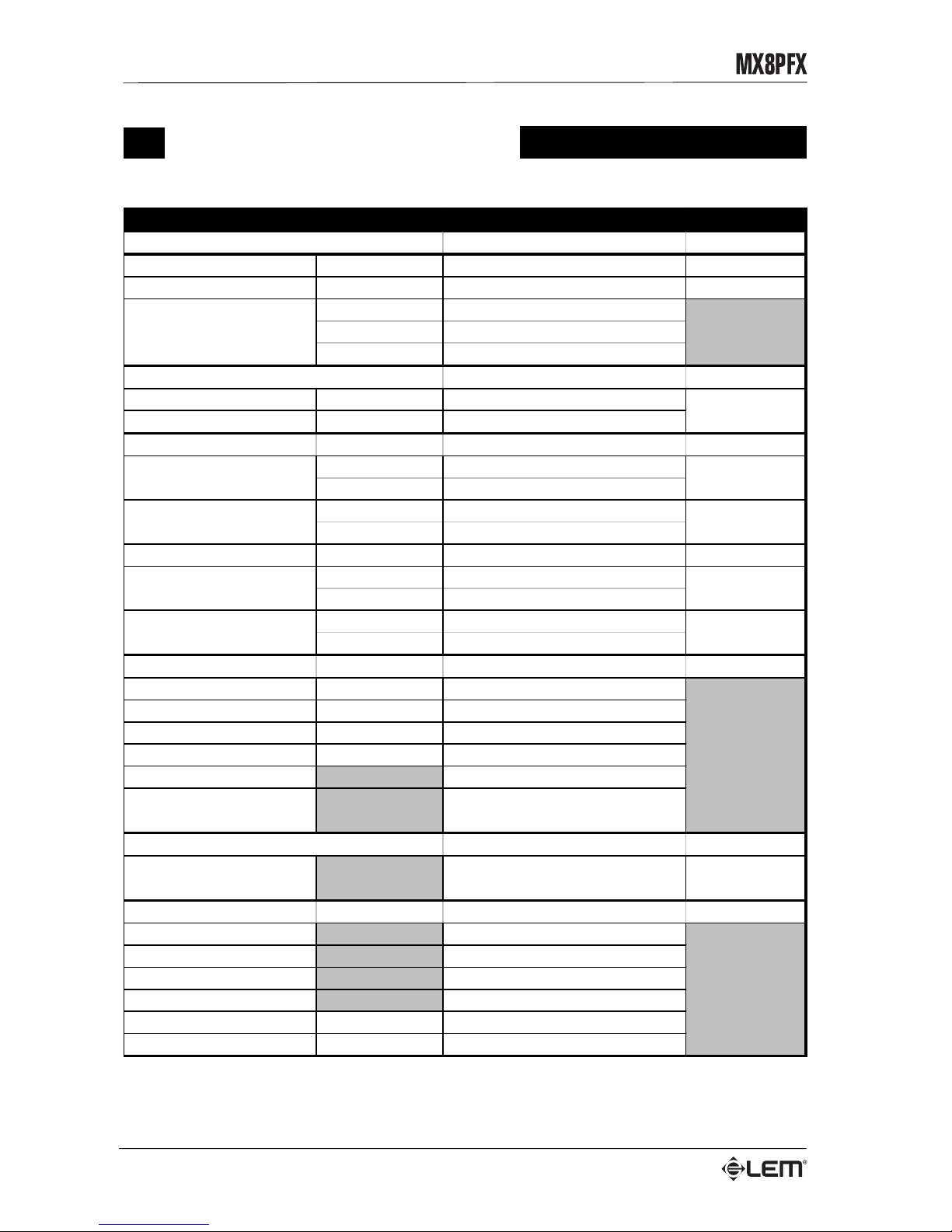
Specifiche tecniche
Specifiche tecniche
SEZIONE LIVELLI & DATI CONNETTORI
CANAL E DI INGRESSO MONO
Ingresso MIC
sensibilità
da -5 a -55dB XLR-F bilanciato
Ingresso LINE
sensibilità
-20dB JACK bilanciato
toni ALTI
±15dB, da 1kHz a 12kHz SHELVING
toni M ED I
±15dB, a 2. 5kHz PEAKING
toni BASSI
±15dB, a 80Hz, SHELVI NG
CANAL E DI INGRESSO STEREO
Ingresso STEREO LINE
sensibilità
-20dB
Ingresso PHONO
sensibilità
-50dB
SEZIONE MASTER
livello di us c it a
+4dB
impedenza
1kOhms
livello di us c it a
+4dB
impedenza
1kOhms
FX RETURN
sensibilità
-20dB JACK sbilanciati
IN
-20dB
OUT
0dB
impedenz a m inim a
220 Ohms
livello di us c it a
7V
DSP
Convertitori A/D
bit
18
Convertitori D/A
bit
18
Dinamica interna
bit
24
Fr equenza di campionamento
kHz
44.1
Numero PRESETS 15
Effetti
HALL REVERB, ROOM REVERB,
PLAT E REVERB, STEREO DELAY
AMPLIFICATORE DI POTENZA
Potenza di uscita EIA
(1 kHz, THD 1%)
50 + 50 Watts / 4 Ohms 2 x JACK
SPECIFICHE GENERALI
Risposta in frequenza 20Hz - 20kHz, -3dB
Hum & Noise -80dB
Distorsione armonica (THD) <0.1% @ 1kHz
Alimentazione vedi targhetta sull'apparato
Peso
kg
4.1
Dimensioni
mm (LxAxP)
270x120x300
RCA phono
Uscita CUFFIA
JACK bilanciati
JACK sbilanciati
Phono RCA
RCA phono
Equalizzatore
MIX output
AUX output
TAPE
Page 17

1
Instructions and installation . . . . . . . . . . . . . . . . . . . . . . . . . . . 2
Introduction. . . . . . . . . . . . . . . . . . . . . . . . . . . . . . . . . . . . . . . . . 3
MONO input channel . . . . . . . . . . . . . . . . . . . . . . . . . . . . . . . . . 4
STEREO input channel . . . . . . . . . . . . . . . . . . . . . . . . . . . . . . . 6
MASTER section . . . . . . . . . . . . . . . . . . . . . . . . . . . . . . . . . . . . . 7
DSP. . . . . . . . . . . . . . . . . . . . . . . . . . . . . . . . . . . . . . . . . . . . . . . . 9
Rear panel . . . . . . . . . . . . . . . . . . . . . . . . . . . . . . . . . . . . . . . . . 10
Connection cables . . . . . . . . . . . . . . . . . . . . . . . . . . . . . . . . . . 11
Connection examples . . . . . . . . . . . . . . . . . . . . . . . . . . . . . . . 12
Technical specifications . . . . . . . . . . . . . . . . . . . . . . . . . . . . . 14
Contents
Contents
Page 18
2
Instructions and installation
✔ ✔
✔ ✔
✔ Connecting the mixer to the mains supply.
Before connecting the amplifier to the mains socket, always make certain that:
- the electric system and mains socket have an adequate grounding, compatible with
the safety norms (if you’re uncertain, consult specialized personnel);
- the mains voltage corresponds to that shown on the rear of the unit (an allowance
of up to ±10% is accepted);
- the power cord is not damaged and has no bare wires;
- the on/off switch is in the OFF position.
Make sure the mixer is also off before disconnecting the power cord from the mains socket.
It is best to lower (or better still close) the output levels and
switch off any amplifiers connected to the
line output of the mixer before switching the mixer on or off: this avoids annoying and sometimes
dangerous (particularly for the speaker cabinets) signal peaks.
When the mixer is switched on, it’s normal for the LEDs to light up for a few moments.
✔ ✔
✔ ✔
✔ Connection and prevention or identification of possible disturbances.
First of all, check that the mixer is installed in a place free from industrial or RF (radio frequency) interference.
Avoid installing your equipment very near radio or TV sets, mobile phones, etc., as these can cause noisy
interference.
When connecting the other components of your sound system, watch out for the so-called “ground loops”,
which could cause hum and jeopardize the mixer’s excellent Signal-to-Noise and low distortion characteristics.
The best way (even if not always feasible) to avoid ground loops is to connect the electric ground of all the
equipment to a single central point (the so-called “star” system). In this case, the central point in sound
systems is the mixer.
✔ ✔
✔ ✔
✔ Protection and maintenance.
Do not force knobs, switches or faders: they have been designed to respond to a light touch and could
be damaged if treated with excessive force.
Take care of the connector cables. Always hold them by the connectors, avoiding pulling the wire and
avoid knots and twists when coiling them: this gives the advantage of increasing their life and reliability.
Avoid exposing the mixer to direct sun, strong heat, intense vibrations, very dusty or damp surroundings,
or even worse, rain: this will avoid eventual malfunction, deterioration or even electric shocks and fires.
Any dust on the mixer should be removed using a soft dry cloth or a brush; never use alcohol, acetone
or solvents.
✔ ✔
✔ ✔
✔ In the event of breakdown
All user-adjustable parts are external and easily accessible.
Never open the amplifier: you could run the risk of serious electric shocks.
In the event of breakdown, contact the nearest GENERALMUSIC/LEM Assistance Centre
✔ ✔
✔ ✔
✔ Conservation of documents and packing.
Keep this manual for future consultation. On this subject, remember a golden rule: equipment always
gets a better price on the secondhand market if it has all its original documentation and packing as well
as being well kept.
Instructions and installation
Page 19
3
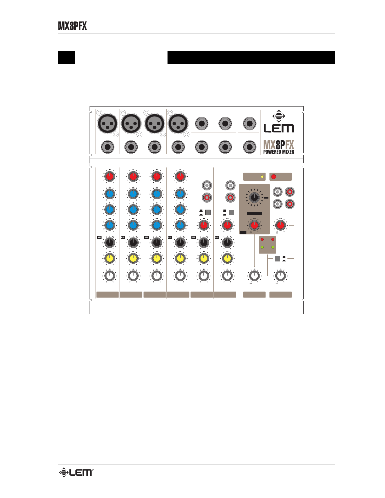
Introduction
Congratulations for having chosen MX8P FX!
POST
AUX
POST
AUX
POST
AUX
POST
AUX
POST
AUX
POST
AUX
MIX
TAPE
SIGNAL
PEAK
RL
TAPE IN
LEVEL
MIX
PHONO PHONO
LINE LINE
LEFT LEFT
RIGHT RIGHT
-5dB -5dB -5dB -5dB
-55dB -55dB -55dB -55dB
LEFT LEFT LEFT LEFT LEFT LEFT
+15 +15 +15 +15
+15 +15 +15 +15
+15 +15 +15 +15
-15 -15 -15 -15
-15 -15 -15 -15
-15 -15 -15 -15
10
MIC
LINE
MIC
LINE
MIC
LINE
MIC
LINE
STEREO
LINE
STEREO
LINE
10 10 10 10 10
10 10 10 10 10 10
000000
000000
RIGHT RIGHT RIGHT RIGHT RIGHT RIGHT
2.5kHz 2.5kHz 2.5kHz 2.5kHz
LEVEL LEVEL LEVEL LEVEL LEVEL LEVEL
PAN PAN PAN PAN BAL BAL
80Hz 80Hz 80Hz 80Hz
LOW LOW LO W LOW
MID MID MID MID
12 kHz 12 kHz 12 kHz 12 kHz
HIGH HIGH HIGH HIGH
GAIN GAIN GAIN GAIN
-5dB
-55dB
GAIN
-5dB
-55dB
GAIN
1 2 3 4 5/6 7/8
MON
AMP
PHONES/
+20
+20
MAX
MAX
TAPE OUT
TAPE IN
L
R
POWER
ON
PHANTOM
+48V
LINE LINE LINE LINE
MIC MIC MIC MIC
1
2
3
4
MIX OUT
AUX
RETURN
L
L/MONO
R
R
HEADPHONES
AUX OUT
DSP
DSP RETURN
AUX RETURN
MUTE
VOC2
VOC1
PERC
PLATE
S/ROOM
DEL2
DEL1
VOC3
CHURCH
DEL5
DEL4
DEL3
M/HALL
L/HALL
L/ROOM
MX8P FX is an extremely versatile amplified mixer able to offer a great number of
functions in a really compact format. Fitted with a powerful built-in amplifier, MX8P FX
has been designed to make its transport, installation and use as easy as possible and
are the ideal solution for anyone requiring (for work or enjoyment purposes) a practical,
reliable powered mixer as well as excellent sound quality.
MX8P FX is equipped with 4 MONO MIC channels and 2 STEREO LINE channels
and offer a range of functions able to easily satisfy a great variety of mixing needs: from
small groups to MIDI musicians and from permanent installations to touring applications.
The built-in DSP includes 15 high-quality REVERB and STEREO DELAY effects, able
to reproduce accurately different kinds of ambients and to enrich not only the voice, but
also any kind of instrument. The extremely compact 50+50 WATTS built-in amplifier
makes it a highly efficient integrated system which is also characterized by the fact that it
is very easy to use
Introduction
Page 20
4
MONO input channel
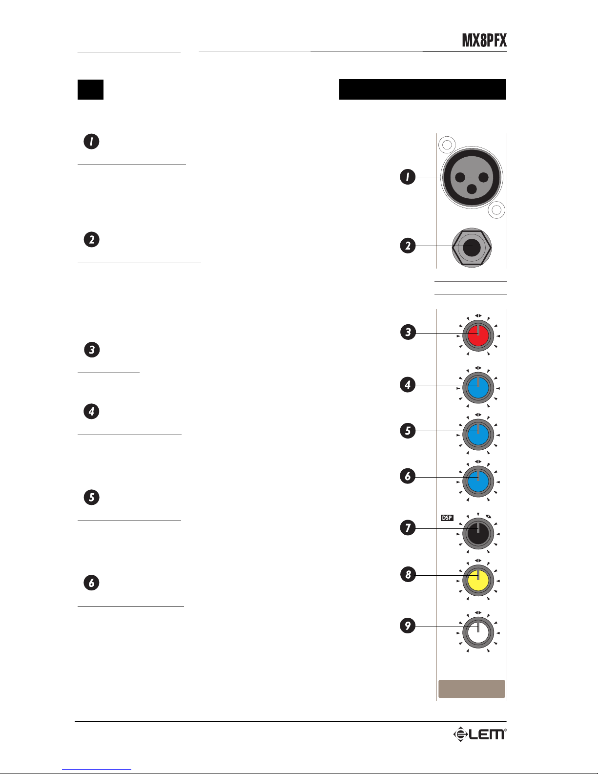
MIC INPUT
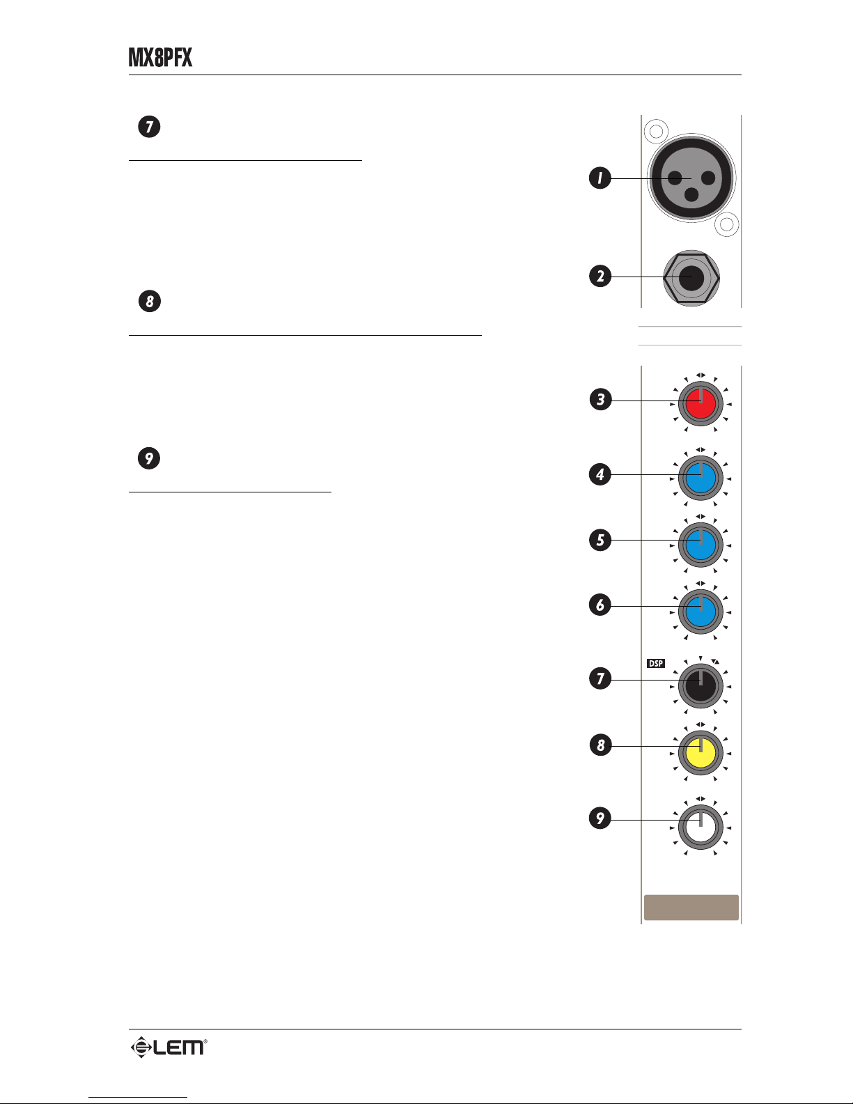
Balanced XLR connector: receives the microphone input signal on the
channel. This input is for use with microphones, but can also accept a
wide range of balanced or unbalanced low impedance signals.
Do not connect keyboards, recorders or other equipment with a line
signal, as the signal level would be too high and probably distorted.
LINE INPUT
Balanced JACK connector: receives the line input signal on the
channel. This input can receive balanced or unbalanced high-impedance
signals from equipment with a high-level output (all instruments
excluding microphones).
Do not connect a microphone to this input: the signal would not be
sufficiently amplified and will probably be poor and disturbed.
GAIN
Gain control: regulates the amplification of external signals
(microphones, instruments, etc.) fed into the channel.
HIGH
HIGH frequency control: gives a 15dB boost or cut at 12 kHz with a
“SHELVING” curve. If you want a brighter, clearer sound, turn the pot
to the right (+15). If on the other hand, the sound is annoyingly treble
or metallic, turn it to the left (-15).
MID
LOW frequency control: gives 15dB boost or cut at 2.5 kHz with a
“PEAKING” curve. If you want a sound more ‘detailed’ in the mid range,
turn the pot to the right (+15). If on the other hand, the sound is too
‘harsh’, turn it to the left (-15).
LOW
LOW frequency control: gives 15dB boost or cut at 80Hz with a
“SHELVING” curve. Using this control, a more “full-bodied” sound can
be obtained, or “booming” or unpleasant effects due to excessive low
frequencies can be eliminated.
MONO input channel
POST
AUX
-5dB
-55dB
LEFT
+15
+15
+15
-15
-15
-15
10
MIC
LINE
10
0
0
RIGHT
2.5kHz
LEVEL
PAN
80Hz
LOW
MID
12 kHz
HIGH
GAIN
1
LINE
MIC
1
Page 21
5
MONO input channel
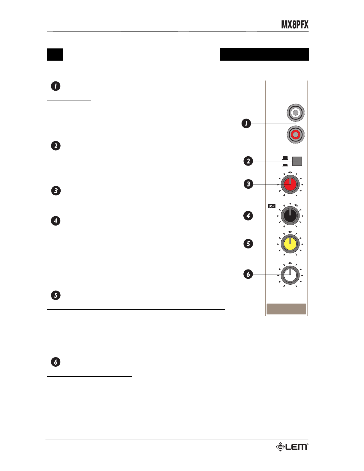
DSP / AUX
Control for the DSP / AUX send level.
Sends the signal both to the internal DSP and to the AUX output,
allowing also the use of an external effect (if needed).
The DSP / AUX send is POST-FADER: this means than the signal is
taken after the control of the channel FADER and therefore its level is
effected by the fader’s setting. For this reason, the DSP / AUX send is
suitable for the use with effect.
PAN
Centre-dented Pan pot for controlling the signal’s pan: regulates
stereo “position” of the signal with respect to the main L&R outputs. If
PAN is turned completely to the LEFT, the signal will only be sent to
MIX LEFT, if it’s turned completely to the RIGHT, the signal will only
be sent to MIX RIGHT. At intermediate settings, the signal is sent to
both MIX LEFT and RIGHT, but in different proportions.
LEVEL
Pot for controlling channel level: regulates the level of each channel
sent to the MIX L&R main outputs.
POST
AUX
-5dB
-55dB
LEFT
+15
+15
+15
-15
-15
-15
10
MIC
LINE
10
0
0
RIGHT
2.5kHz
LEVEL
PAN
80Hz
LOW
MID
12 kHz
HIGH
GAIN
1
LINE
MIC
1
Page 22
6
POST
AUX
PHONO
LINE
LEFT
RIGHT
LEFT
STEREO
LINE
10
10
0
0
RIGHT
LEVEL
BAL
-5dB
-55dB
GAIN
7/8
STEREO input channel
STEREO input channel
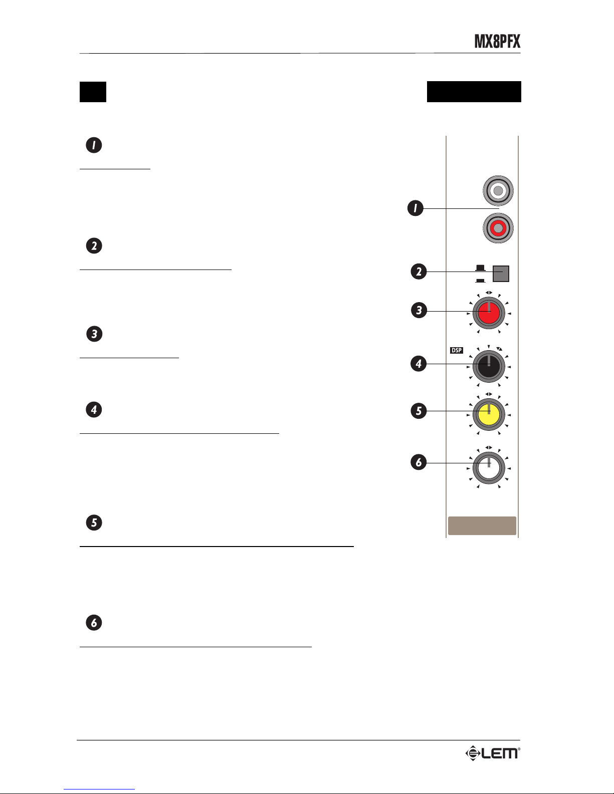
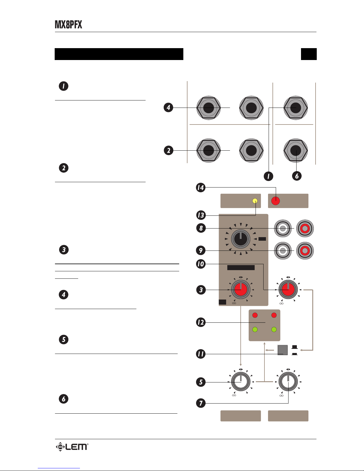
STEREO INPUT
RCA connector: receives the STEREO LINE input signal on the
channel.
According to the position of the LINE/PHONO SELECTOR, this inputs
can accept line signal coming from high-level output devices (LINE) or
signals with RIIA EQ coming from turntables (PHONO).
LINE/PHONO
Input selector: allows to select the kind of input signal:
• button UP = line signal;
• button DOWN = phono signal.
GAIN
Gain control: regulates the amplification of external signals.
DSP / AUX
Control for the DSP / AUX send level.
Sends the signal both to the internal DSP and to the AUX output,
allowing also the use of an external effect (if needed).
The DSP / AUX send is POST-FADER: this means than the signal is
taken after the control of the channel FADER and therefore its level is
effected by the fader’s setting. For this reason, the DSP / AUX send is
suitable for the use with effect.
BAL
Centre-dented control of the balance of the signal on the main
outputs.
The BAL control has a balancing effect on the levels of the two LEFT & RIGHT parts of the STEREO
signal and works as follows:
• turning to the LEFT lowers the RIGHT signal level on MIX RIGHT;
• turning to the RIGHT lowers the LEFT signal on MIX LEFT.
LEVEL
Pot for controlling channel level: regulates the level of each channel sent to the MIX L&R main outputs.
Page 23
7
MASTER section
MASTER section
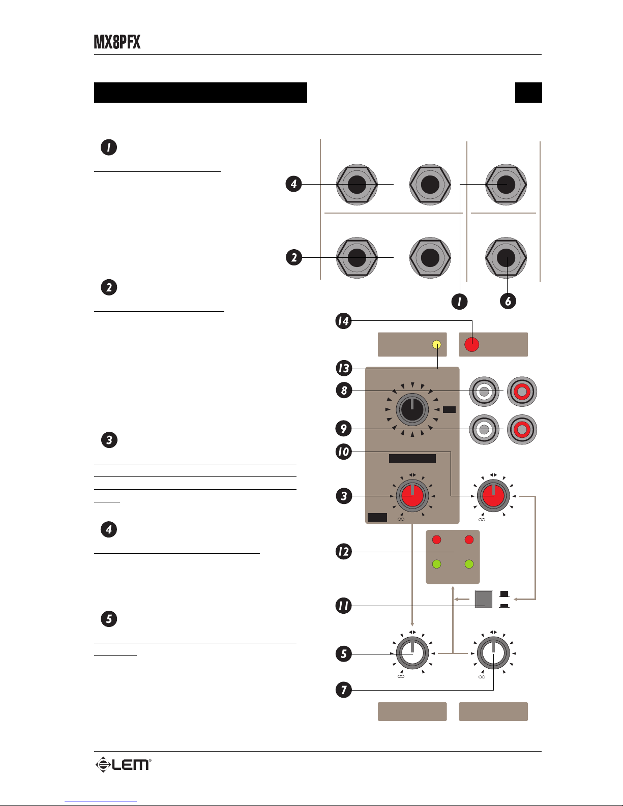
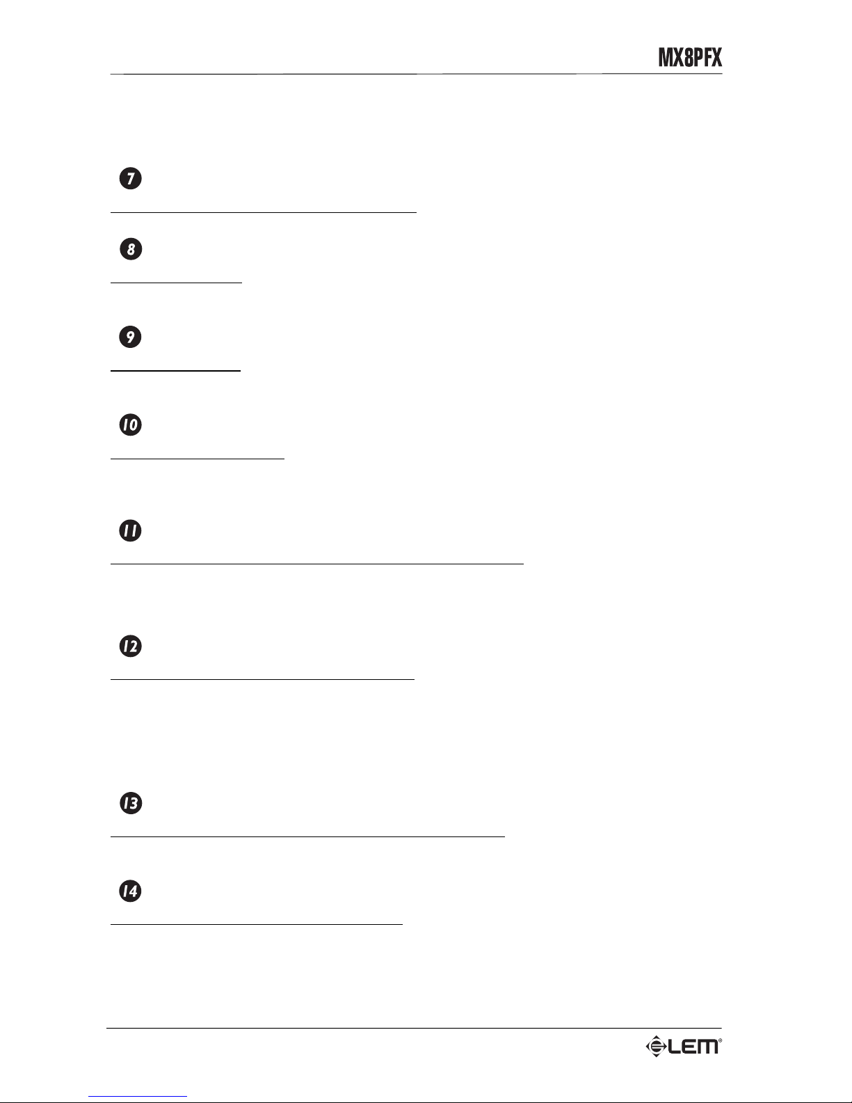
AUX OUT
Unbalanced JACK connectors:
these connectors feed out the sum of
the signals arriving from the relative
DSP / AUX sends of the input
channels. The DSP / AUX send is
POST-FADER and is therefore
mainly intended for use with
EFFECTS.
AUX IN L&R
Unbalanced JACK connectors:
these are the connectors of the
auxiliary stereo input available on the
MX8P FX. This input, whose signal is sent directly
to MIX L&R, can be used for the return signal from
outboard effects or for connecting any instrument
or equipment with a line output (e.g. keyboards,
cassette recorder or CD turntable).
DSP / AUX RETURN
Pot for controlling the level of the auxiliary
stereo input and of the BUILT-IN DSP (see DSP
section).
MIX L&R OUT
Balanced JACK connectors: these are the
connectors of the mixer’s main line outputs, from
which the program from MIX L&R is fed out.
MIX
Pot for STEREO control of the general volume:
controls the level of the signal arriving from the
input channel sent to the two main MIX L&R
outputs, to the TAPE OUT output and to the inputs
of the built-in amplifier.
PHONES OUT
STEREO JACK headphone output connector:
only stereo headphones with a minimum
MIX
TAPE
SIGNAL
PEAK
RL
TAPE IN
LEVEL
MIX
MON
AMP
PHONES/
+20
+20
MAX
MAX
TAPE OUT
TAPE IN
L
R
POWER
ON
PHANTOM
+48V
SP
DSP RETURN
AUX RETURN
MUTE
OC2
O
C1
ERC
PLATE
S/ROOM
DEL2
DEL1
VOC3
CHURCH
DEL5
DEL4
DEL3
M/HALL
L/HALL
L/ROOM
MIX OUT
AUX
RETURN
L
L/MONO
R
R
HEADPHONES
AUX OUT
Page 24
8
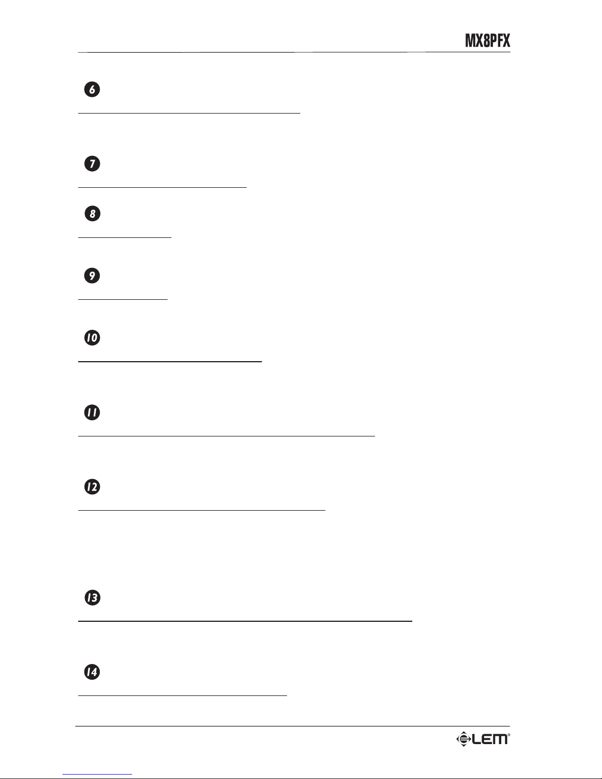
impedance of 220 Ohms should be connected to this output. It is possible to connect this output also to
an external amplifier for monitoring.
PHONES LEVEL
Pot for controlling the level of headphone output.
TAPE OUT L&R
Two RCA connectors: send out the signal taken from MIX and normally intended for STEREO recording.
These outputs can be connected to the inputs of a recorder.
TAPE IN L&R
Two RCA connectors: receive external signals from STEREO tape recorders, CD player, DAT, etc. These
inputs can be connected to the outputs of your equipment.
TAPE IN
TAPE IN input level control: regulates the level of a signal arriving from an external tape recorder to
MIX L&R. During recording, set the TAPE IN control in the “0” (closed) position to avoid annoying and
“dangerous” feedback or signal loops.
MIX/TAPE
Button for the assignment of the TAPE IN signal to the MIX output:
• button UP (MIX) = the TAPE IN signal is sent only to the headphones output;
• button DOWN (TAPE) = the TAPE IN signal is sent is sent also to the MIX output.
LEVEL
LEDs for the display of the MIX L&R signal level.
The LEDs are of two different colors:
• green/SIGNAL = show the normal operative level of the signal;
• red/PEAK = show a too high signal level (OVERLOAD).
To ensure clean, distortion-free signals and to avoid damaging the components of your sound system,
try to avoid making the red LEDs lighting up repeatedly.
+48V
LED indicating when the +48V phantom power is switched on: this LED lights up when the button
on the connector panel on the rear of the mixer is pressed.
ON
LED indicating when the mixer is switched on: this LED lights up when the button on the connector
panel on the rear of the mixer is pressed.
MASTER section
Page 25
9
DSP
DSP
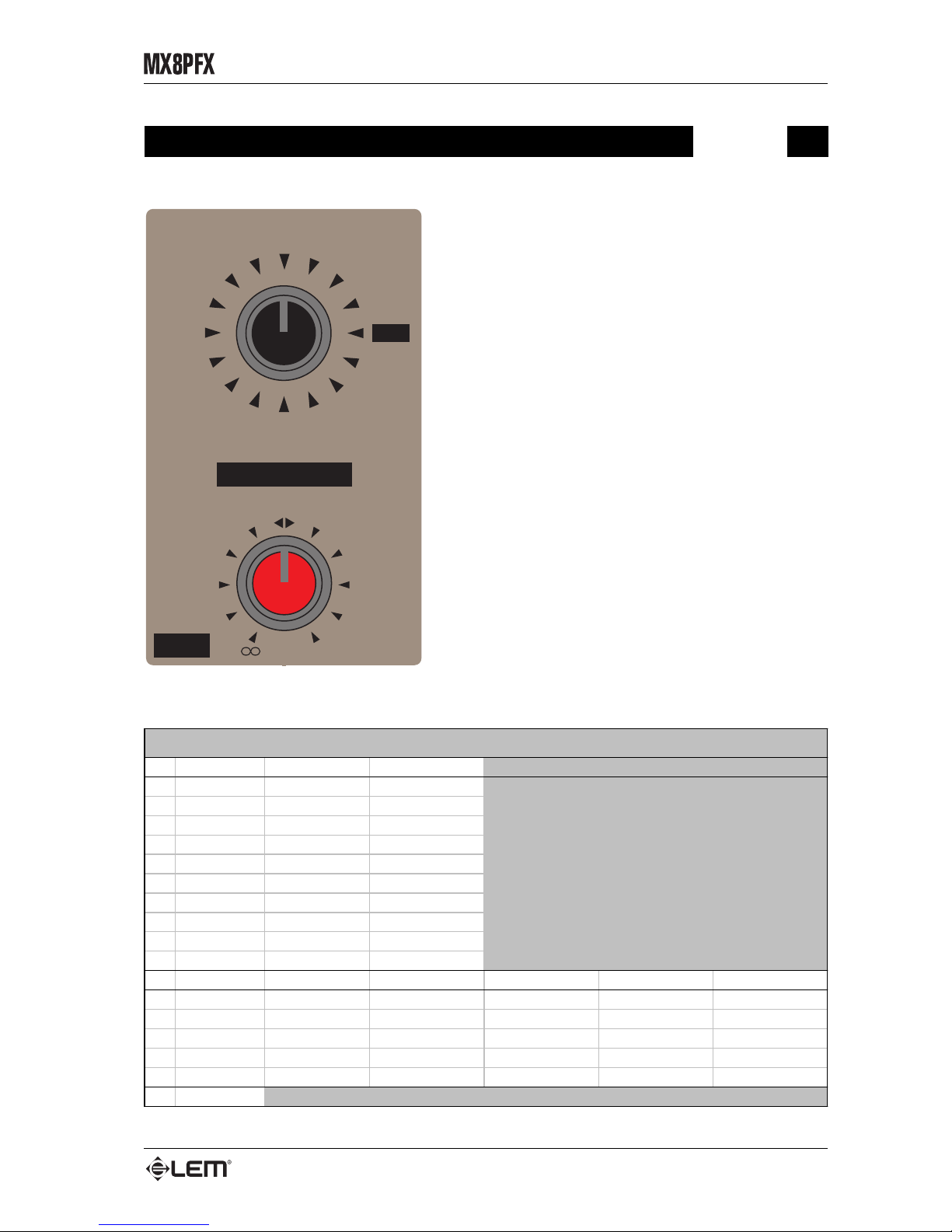
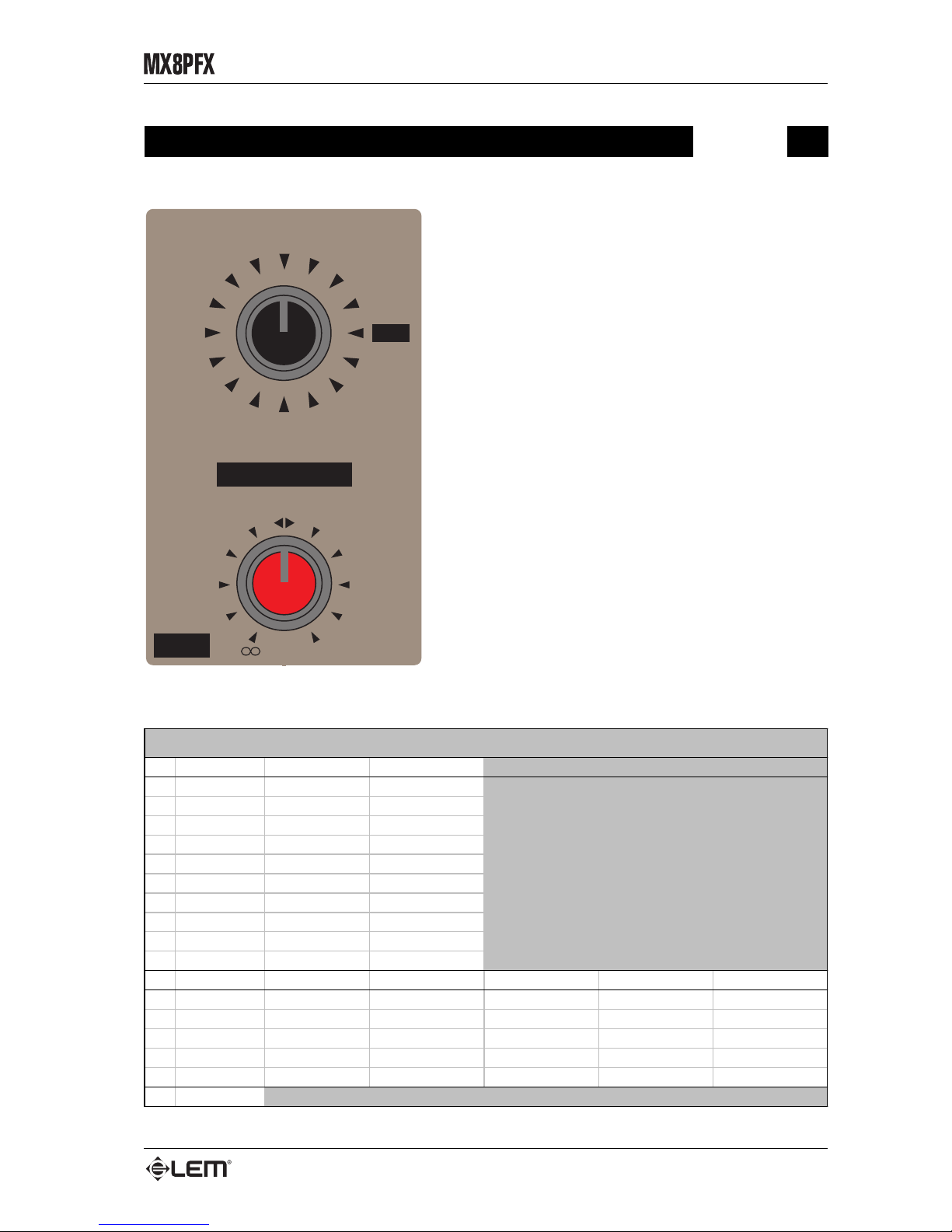
The MX8P FX is fitted with a built-in DSP, including 15
high-quality REVERB and STEREO DELAY effects
able to reproduce accurately different kinds of ambients
and to enrich not only the voice, but also any kind of
instrument.
The 15 PRESETS can be selected by means of a
convenient 16-position encoder. In the last position
there’s a MUTE PRESET that can be used to cut out
the effect on all the channels.
The signal is sent to the effect through the channel DSP
/ AUX send. The effect level sent to the MIX outputs is
controlled by the DSP RETURN knob.
NOTE: if you need to use an external effect connected to the AUX
OUTPUT and to the AUX RETURN INPUTS, the internal DSP can
be switched off selecting the MUTE PRESET. The internal DSP
and the external effect can be also used together, but this is not
an advisable condition.
The following table include the list and the main
parameters of the 15 PRESETS available in the internal
DSP.
+20
DSP
DSP RETURN
AUX RETURN
MUTE
VOC2
VOC1
PERC
PLATE
S/ROOM
DEL2
DEL1
VOC3
CHURCH
DEL5
DEL4
DEL3
M/HALL
L/HALL
L/ROOM
No. PRESET Effect REV TIME (s)
1 CATHEDRAL HALL REVERB 5.0
2 LARGE HAL L HALL REVERB 3.0
3 MID HALL HAL L REVE RB 1.7
4LARGE ROOMROOM REV ERB 1.5
5 SMALL ROOM ROOM REVE RB 0.8
6PLATE PLATE REVERB 1.5
7PERCUSSIONPLATE REVERB 1.2
8VOCAL 1 PLATE REVERB 3.0
9VOCAL 2 PLATE REVERB 1.5
10 VOCAL 3 PLATE REVERB 0.9
No. PRESET Effect LEFT DELAY (ms) RIGHT DELAY (ms) LEFT FB (%) RIGHT FB (%)
11 DELAY 1 ST EREO DELA Y 100 200 40 20
12 DELAY 2 ST EREO DELA Y 200 400 30 15
13 DELAY 3 ST EREO DELA Y 300 600 30 15
14 DELAY 4 ST EREO DELA Y 200 210 30 30
15 DELAY 5 ST EREO DELA Y 300 310 20 20
16 MUTE
PRESET LIST
Page 26
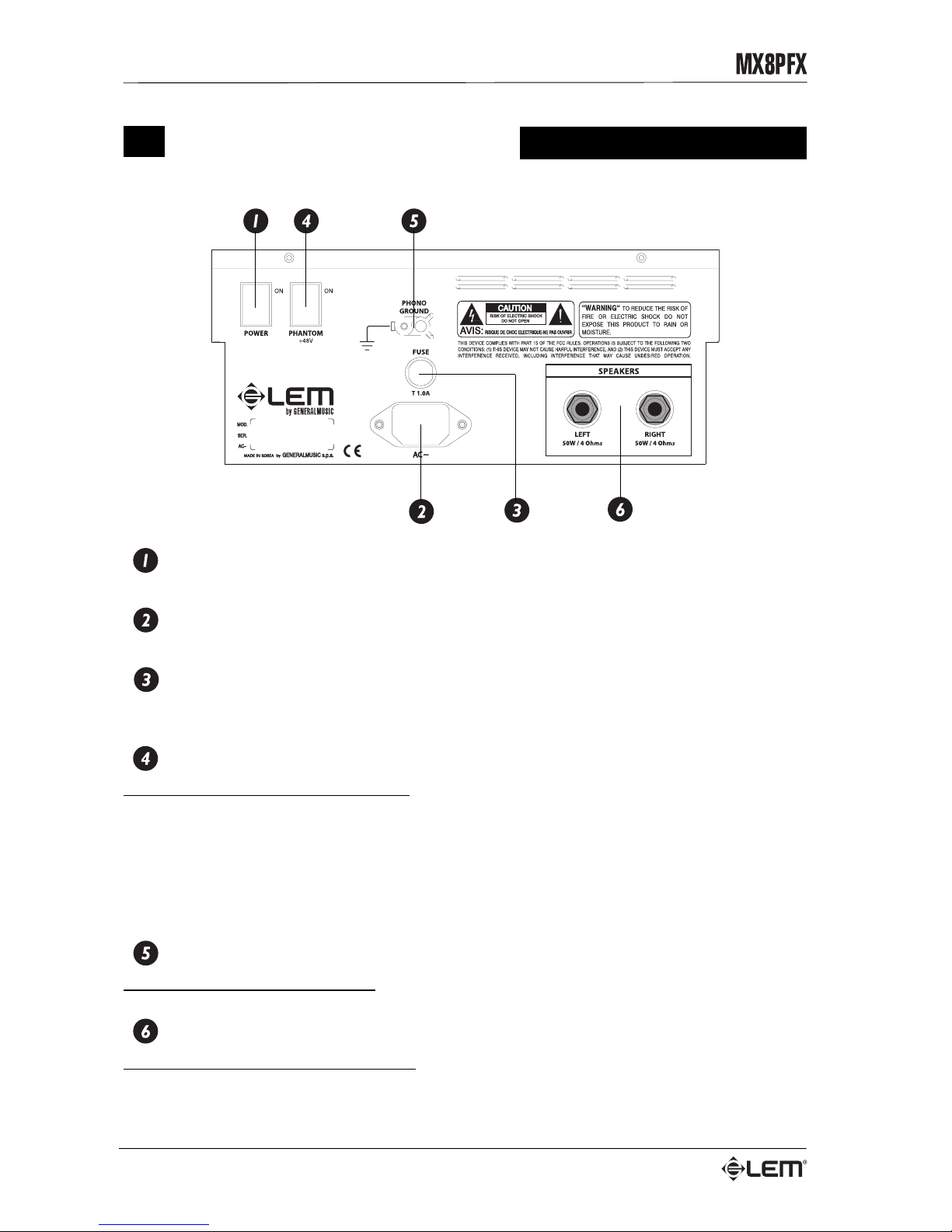
10
Rear panel
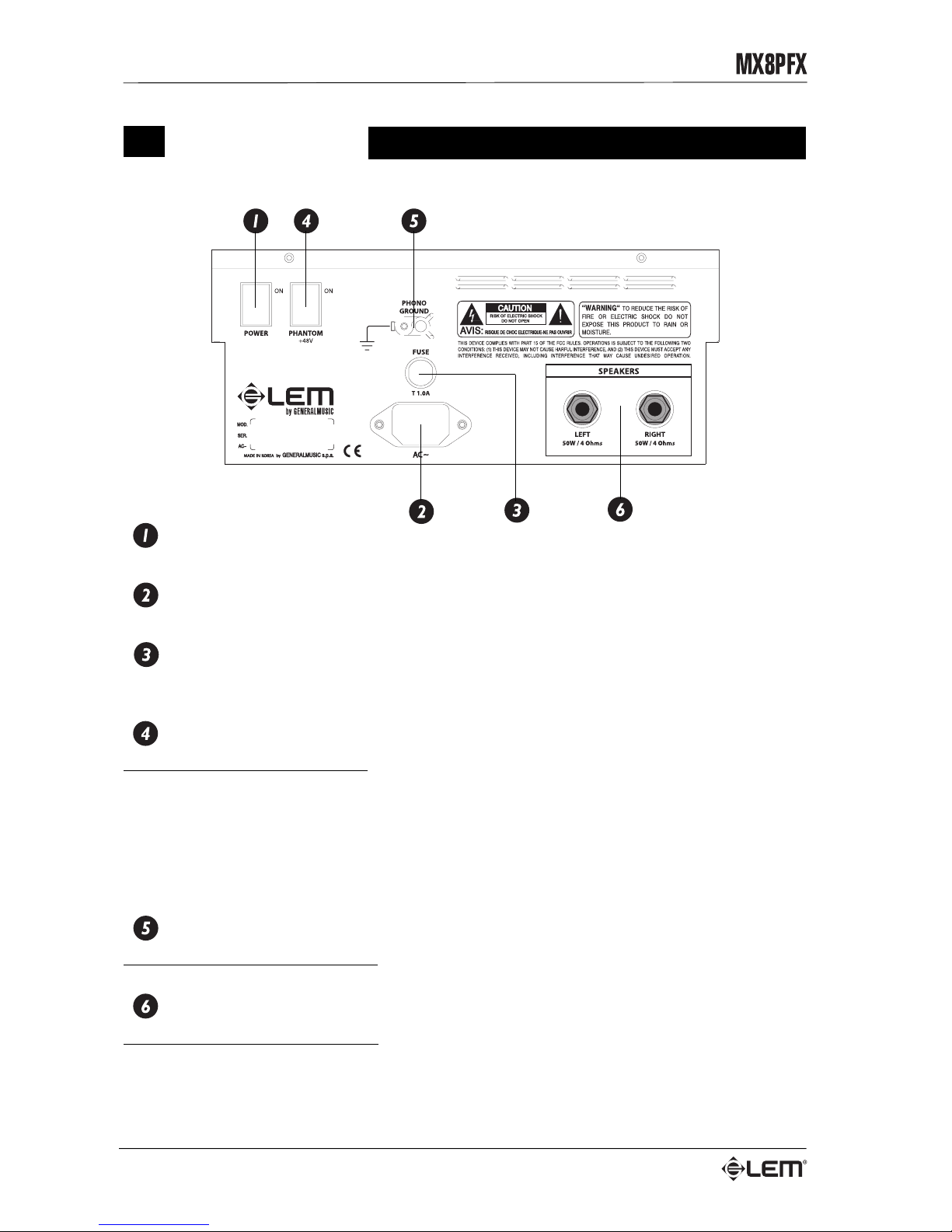
Mixer on/off switch.
Power supply socket.
Main fuse holder
In the event of breaking, always replace the fuse with same type and rating.
+48V
+48V Phantom power supply button: this button switches on the +48V power supply for all the MIC inputs
(XLR-F connector) of the MONO input channels and allows condenser microphones to be used on them.
When the PHANTOM power supply is switched on make certain that cables with BALANCED XLR
connectors are ALWAYS used to connect the microphones: this precaution is extremely important for
avoiding damage in the event of both condenser and normal (dynamic) microphones being used
simultaneously. Switch on the phantom power supply only after having connected the condenser
microphone to the input and only with the channel fader closed to avoid output signal peaks.
Phono ground
Ground connector for the turntables: connect here the ground cable of the turntable.
Powered outputs
MIX LEFT & RIGHT powered outputs: connect these outputs to the loudspeaker enclosures.
Be careful that the overall impedance of the speakers connected is not below 4 Ohms, because in this
case the amplifier could protect himself. Only use “power” cables (speaker enclosure cables), not “signal”
cables (screened cables used for instruments and microphones).
Rear panel
Page 27
11
Connection cables
Connection cables
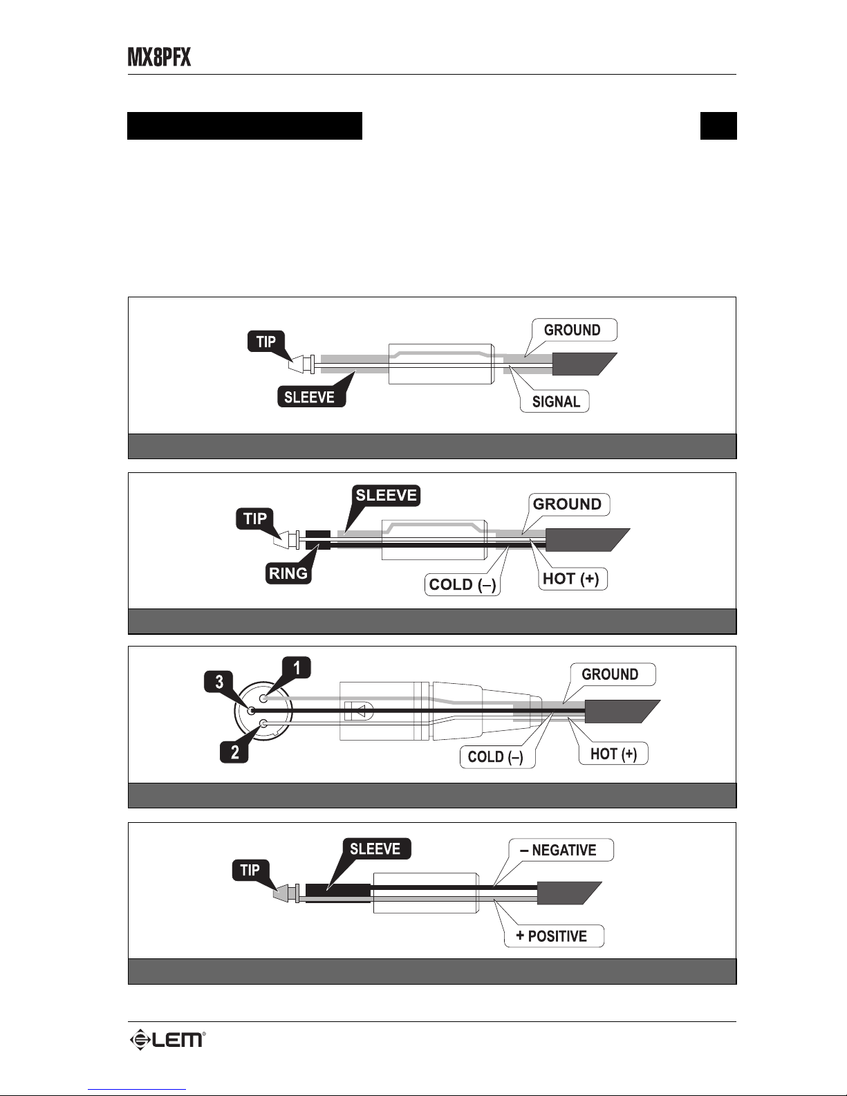
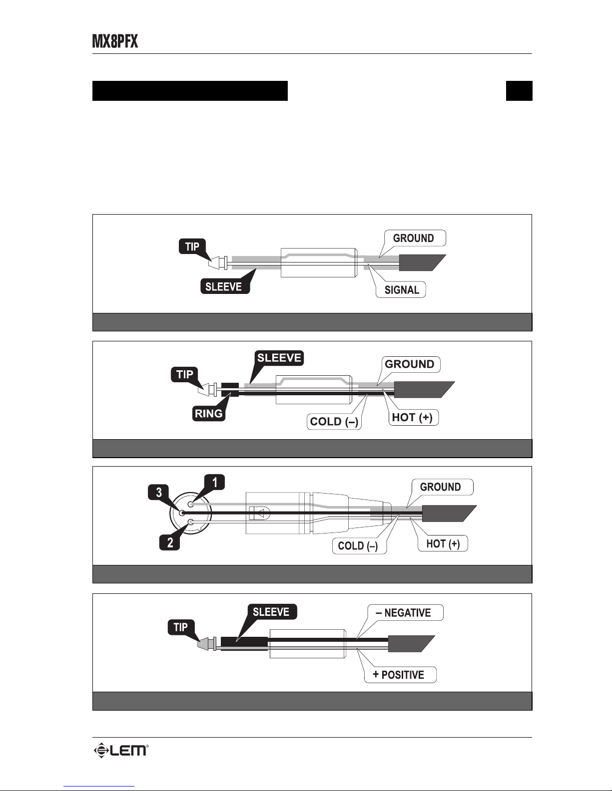
UNBALANCED JACK connector
BALANCED JACK connector
BALANCED XLR-M connector
JACK POWER cable
The following are wiring diagrams for the connectors used with MX8P FX. Take care of the connector cables,
always holding them by the connectors and avoiding pulling the wire and avoid knots and twists when coiling them:
this gives the advantage of increasing their life and reliability, which is always to your advantage. Periodically check
that your cables are in good condition and are correctly wired and that all their contacts are perfect: a great number
of problems (faulty contacts, ground hum, discharges, etc.) are caused entirely by using unsuitable or faulty cables.
Page 28
12
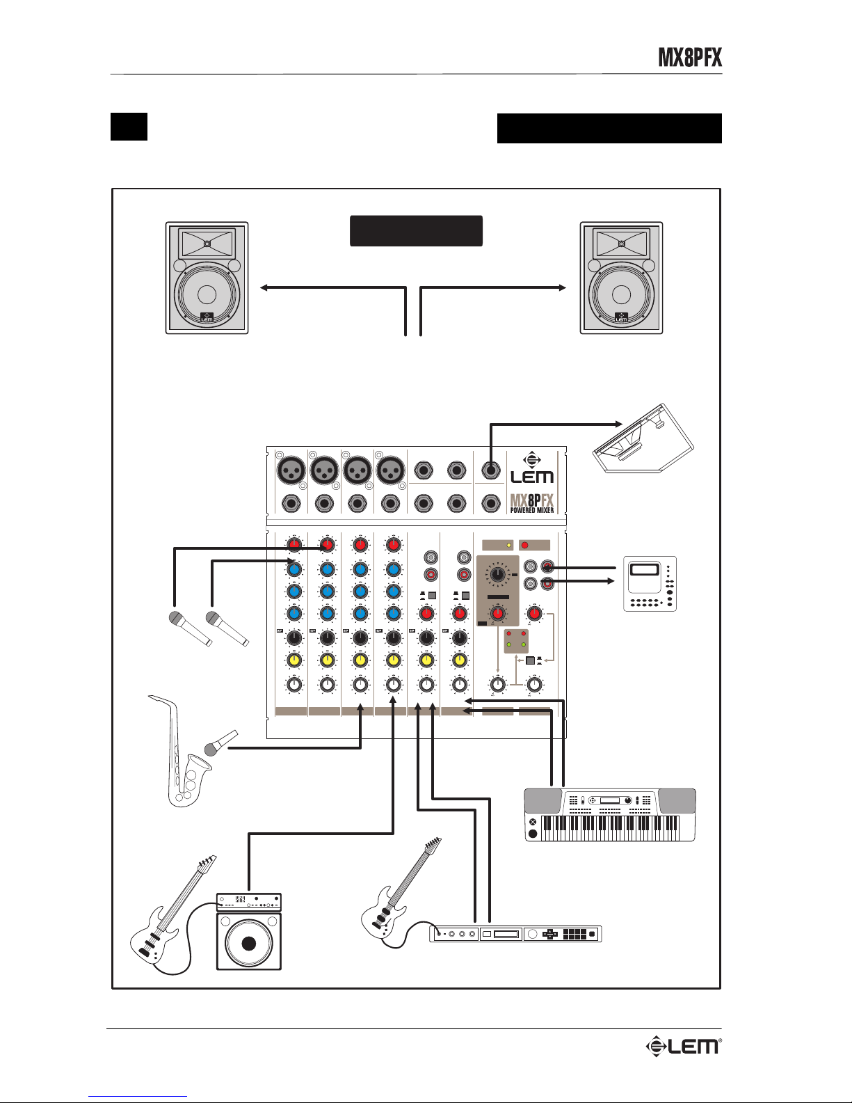
Connection examples
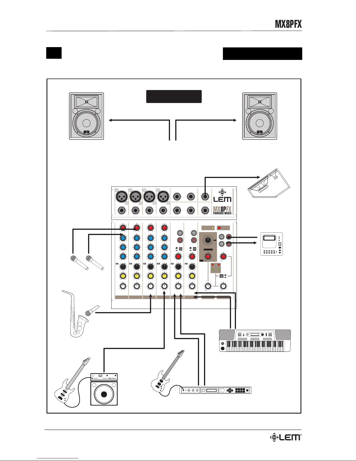
Connection examples
POST
AUX
POST
AUX
POST
AUX
POST
AUX
POST
AUX
POST
AUX
MIX
TAPE
SIGNAL
PEAK
RL
TAPE IN
LEVEL
MIX
PHONO PHONO
LINE LINE
LEFT LEFT
RIGHT RIGHT
-5dB -5dB -5dB -5dB-55dB -55dB -55dB -55dB
LEFT LEFT LEFT LEFT LEFT LEFT
+15 +15 +15 +15
+15 +15 +15 +15
+15 +15 +15 +15
-15 -15 -15 -15
-15 -15 -15 -15
-15 -15 -15 -15
10
MIC
LINE
MIC
LINE
MIC
LINE
MIC
LINE
STEREO
LINE
STEREO
LINE
10 10 10 10 10
10 10 10 10 10 10
000000
000000
RIGHT RIGHT RIGHT RIGHT RIGHT RIGHT
2.5kHz 2.5kHz 2.5kHz 2.5kHz
LEVEL LEVEL LEVEL LEVEL LEVEL LEVEL
PAN PAN PAN PAN BAL BAL
80Hz 80Hz 80Hz 80Hz
LOW LOW LOW LOW
MID MID MID MID
12 kHz 12 kHz 12 kHz 12 kHz
HIGH HIGH HIGH HIGH
GAIN GAIN GAIN GAIN
-5dB -55dB
GAIN
-5dB -55dB
GAIN
12345/67/8
MON
AMP
PHONES/
+20
+20
MAX
MAX
TAPE OUT
TAPE IN
L
R
POWER
ON
PHANTOM
+48V
LINE LINE LINE LINE
MIC MIC MIC MIC
1
2
3
4
MIX OUT
AUX
RETURN
L
L/MONO
R
R
HEADPHONES
AUX OUT
DSP
DSP RETURN
AUX RETURN
MUTE
VOC2
VOC1
PERC
PLATE
S/ROOM
DEL2
DEL1
VOC3
CHURCH
DEL5
DEL4
DEL3
M/HALL
L/HALL
L/ROOM
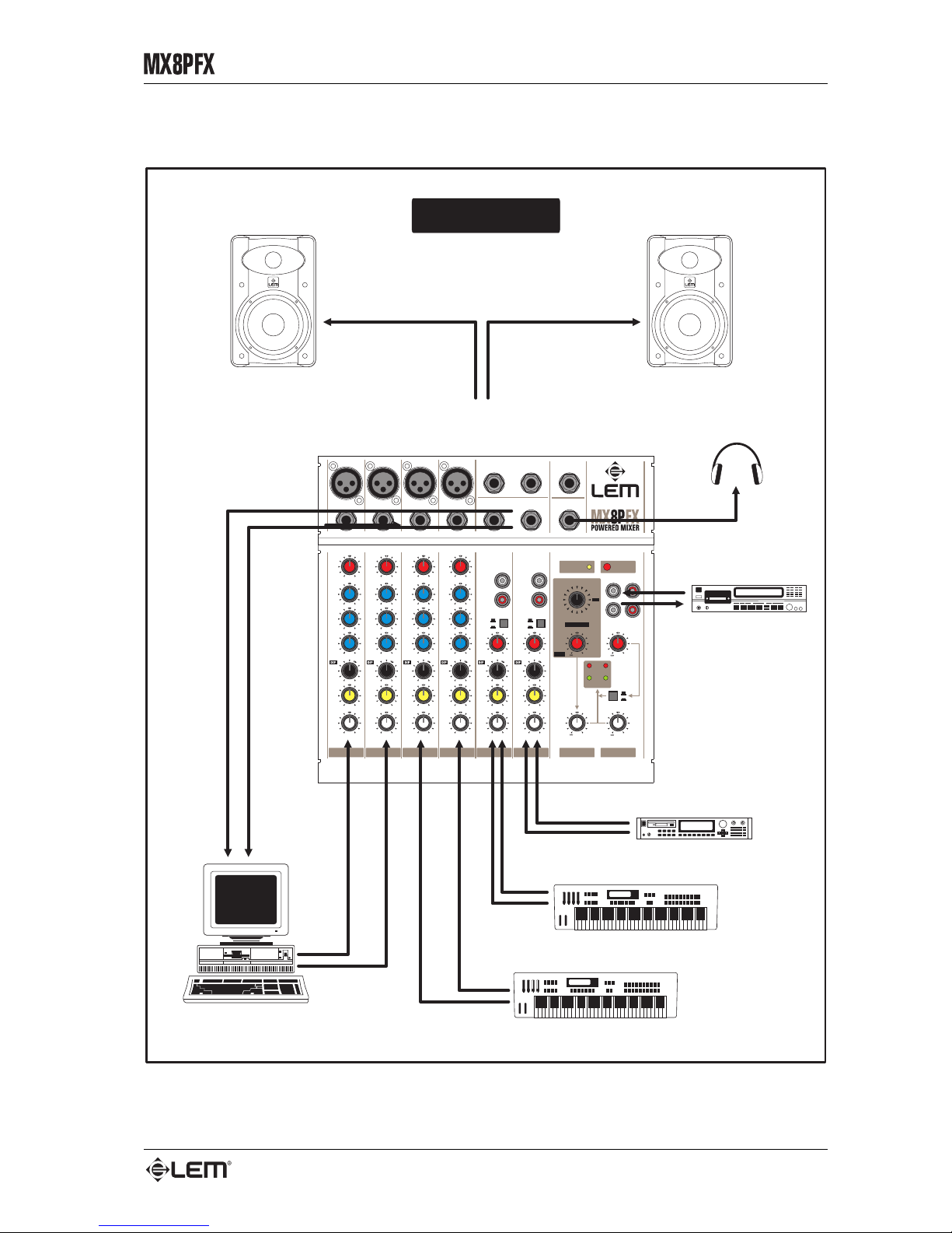
LIVE SET
MINIDISC RECORDER
to TAPE IN
from TAPE OUT
VOCAL MIC
CH 1&2
BRASS
CH 3
STEREO GUITAR
CH 5/6
STEREO KEYBOARD
CH 7/8
BASS
CH 4
MAIN P.A.
from L&R POWER OUTPUTS
AMPLIFIED MONITOR
from AUX OUT
Page 29
13
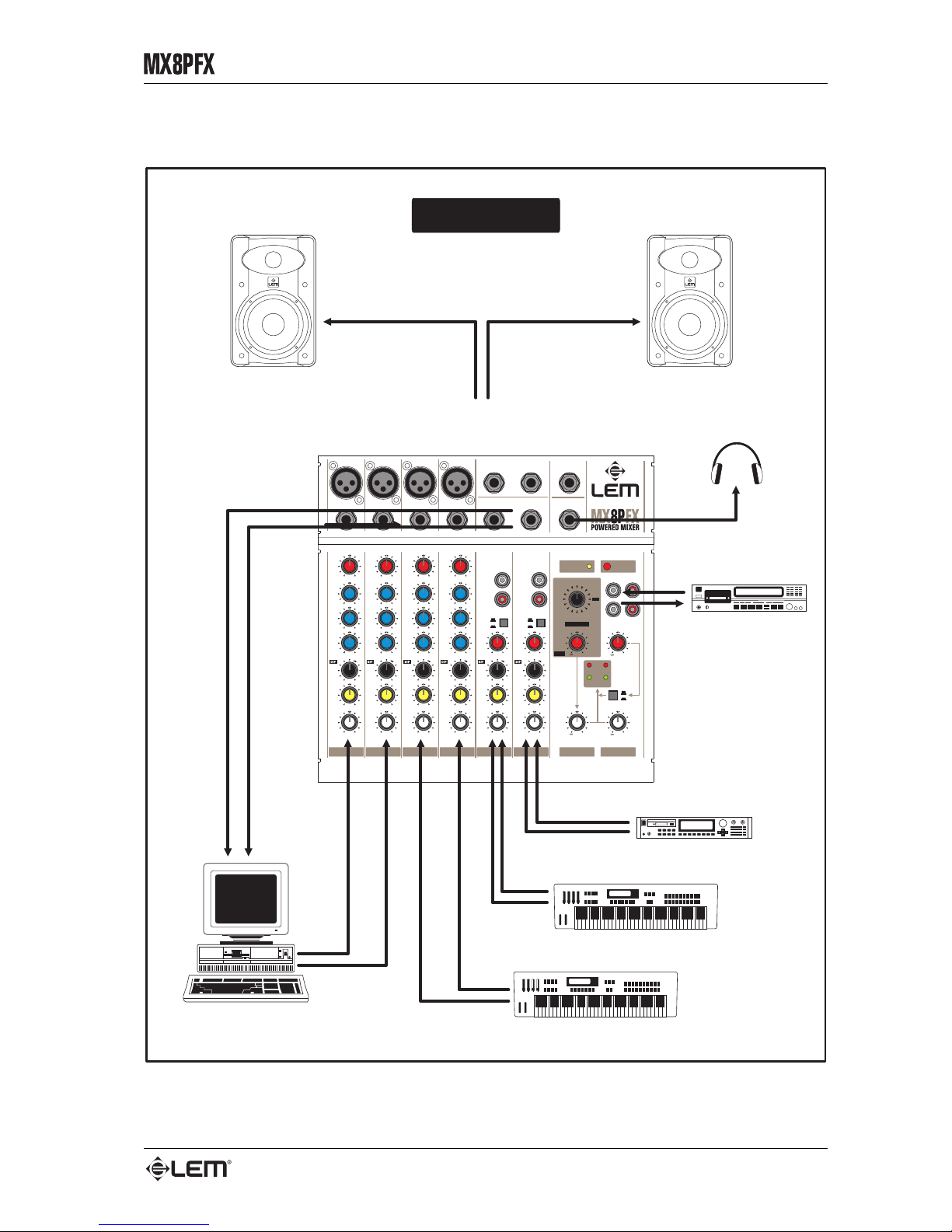
Connection examples
POST
AUX
POST
AUX
POST
AUX
POST
AUX
POST
AUX
POST
AUX
MIX
TAPE
SIGNAL
PEAK
RL
TAPE IN
LEVEL
MIX
PHONO PHONO
LINE LINE
LEFT LEFT
RIGHT RIGHT
-5dB -5dB -5dB -5dB-55dB -55dB -55dB -55dB
LEFT LEFT LEFT LEFT LEFT LEFT
+15 +15 +15 +15
+15 +15 +15 +15
+15 +15 +15 +15
-15 -15 -15 -15
-15 -15 -15 -15
-15 -15 -15 -15
10
MIC
LINE
MIC
LINE
MIC
LINE
MIC
LINE
STEREO
LINE
STEREO
LINE
10 10 10 10 10
10 10 10 10 10 10
000000
000000
RIGHT RIGHT RIGHT RIGHT RIGHT RIGHT
2.5kHz 2.5kHz 2.5kHz 2.5kHz
LEVEL LEVEL LEVEL LEVEL LEVEL LEVEL
PAN PAN PAN PAN BAL BAL
80Hz 80Hz 80Hz 80Hz
LOW LOW LOW LOW
MID MID MID MID
12 kHz 12 kHz 12 kHz 12 kHz
HIGH HIGH HIGH HIGH
GAIN GAIN GAIN GAIN
-5dB -55dB
GAIN
-5dB -55dB
GAIN
12345/67/8
MON
AMP
PHONES/
+20
+20
MAX
MAX
TAPE OUT
TAPE IN
L
R
POWER
ON
PHANTOM
+48V
LINE LINE LINE LINE
MIC MIC MIC MIC
1
2
3
4
MIX OUT
AUX
RETURN
L
L/MONO
R
R
HEADPHONES
AUX OUT
DSP
DSP RETURN
AUX RETURN
MUTE
VOC2
VOC1
PERC
PLATE
S/ROOM
DEL2
DEL1
VOC3
CHURCH
DEL5
DEL4
DEL3
M/HALL
L/HALL
L/ROOM
DAT RECORDER
to TAPE IN
from TAPE OUT
MONITORING SYSTEM
from L&R POWER OUTPUTS
HEADPHONES
STEREO KEYBOARD
CH 5/6
STEREO SAMPLER
CH 7/8
STEREO KEYBOARD
CH 3&4
MULTIMEDIA PC
HOME SET
CH 1&2
from
AUX OUT
Page 30
14
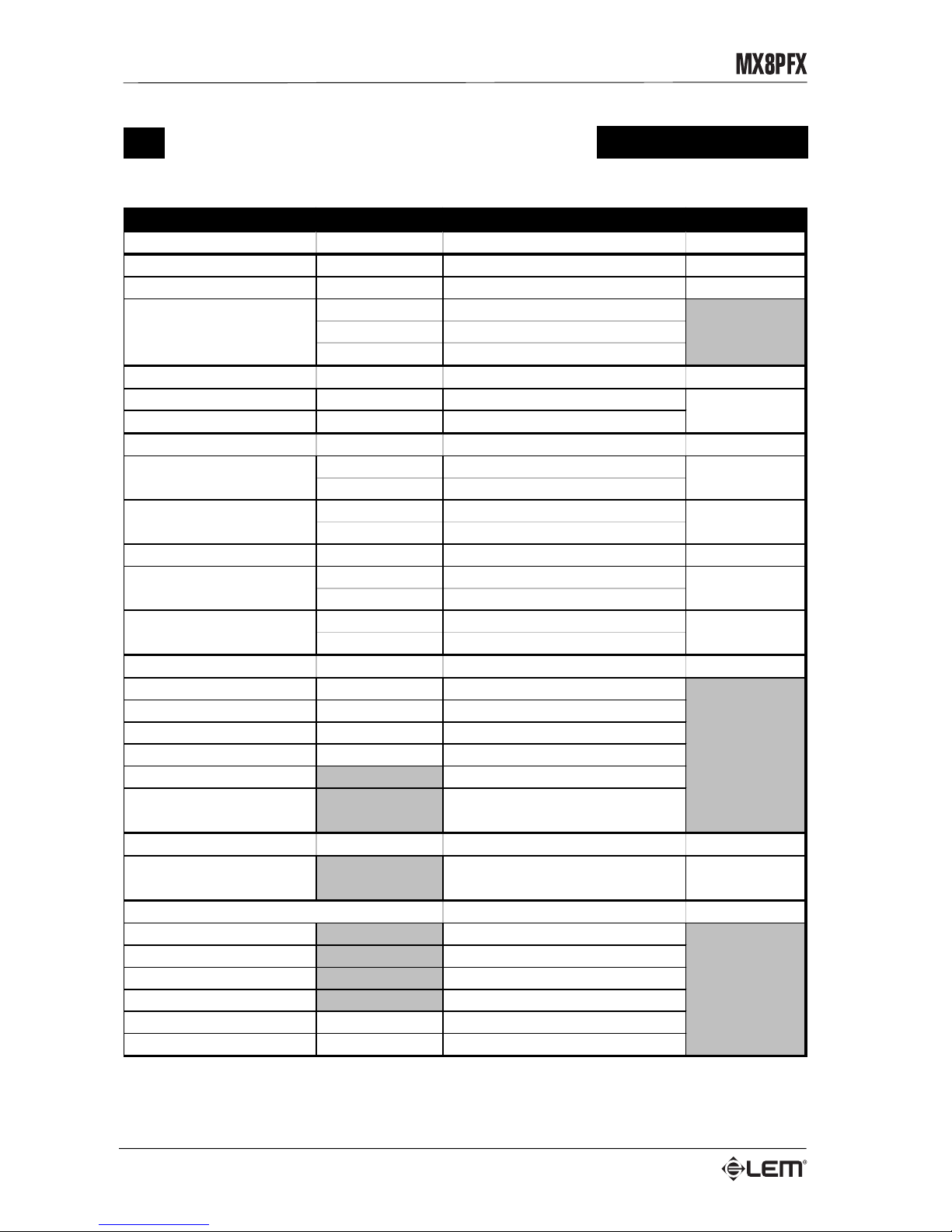
Technical specifications
Technical specifications
SECTION LEVELS & DATA CONNECTORS
MONO INPUT CHANNEL
MIC input
sensitivity
from -5 to - 5 5dB XLR-F balanced
LINE inout
sensitivity
-20dB JACK balanced
HIGH
±15dB, @ 1 kHz a 12kHz SHELVING
MID
±15dB @ 2.5kHz PEAKING
LOW
±15dB @ 80Hz, SHELVI NG
STEREO INPUT CHANNEL
STEREO LINE input channel
sensitivity
-20dB
PHONO inout channel
sensitivity
-50dB
MASTER SECTION
output lev el
+4dB
impedance
1kOhms
output lev el
+4dB
impedance
1kOhms
FX RETURN
sensitivity
-20dB JACK unbalanced
IN
-20dB
OUT
0dB
minim um im pedanc e
220 Ohms
output lev el
7V
DSP
A/D converters
bit
18
D/A converters
bit
18
Internal dynamics
bit
24
Sampling frequency
kHz
44.1
PRESETS number 15
Effects
HALL REVERB, ROOM REVERB,
PLAT E REVERB, STEREO DELAY
POWER AMPLIFIER
EIA output power
(1 kHz, THD 1%)
50 + 50 Watts / 4 Ohms 2 x JACK
GENERALI SPECIFICATIONS
Fr equncy response 20Hz - 20kHz, -3dB
Hum & Noise -80dB
Harmonic distortion (THD) <0.1% @ 1kHz
Power supply see label on the apparatus
Weight
kg
2.9
Dimensions
mm (WxHxD)
270x120x300
JACK stereoHEADPHONES
EQ
MIX output
AUX output
TAPE
RCA phono
JACK balanced
JACK unbalanced
RCA phono
Page 31

FEDERAL COMMUNICATIONS COMMISSION
NOTE: This equipment has been tested and found to comply with the limits for a Class A
digital device, pursuant to Part 15 of FCC Rules. These limits are designed to provide
reasonable protection against harmful interference when the equipment is operated in a
commercial environment. This equipment generates, uses and can radiate radio frequency
energy and, if not installed and used in accordance with the instruction manual, may cause
harmful interference in which case the user will be required to correct the interference at his
own expense.
CAUTION: Changes or modifications to this product not expressly approved by the
manufacturer could void the user’s authority to operate this product.
Le informazioni contenute in questo documento sono state attentamente redatte e controllate. Tuttavia
non è assunta alcuna responsabilità per eventuali inesatezze.
Tutti i diritti sono riservati e in questo documento non può essere copiato, fotocopiato, riprodotto per intero
o in parte senza previo consenso scritto della GENERALMUSIC S.p.A.
GENERALMUSIC si riserva il diritto di apportare senza preavviso cambiamenti e modifiche estetiche,
funzionali o di design a ciascun proprio prodotto.
GENERALMUSIC non assume alcuna responsabilità sull’uso o sull’applicazione dei prodotti o dei circuiti
qui descritti.
STAMPATO IN ITALIA
The information contained in this publication has been carefully prepared and checked. However no
responsibility will be taken for any errors.
All rights are reserved and this document cannot be copied, photocopied or reproducted in part or
completely without written consent being obtained in advance from GENERALMUSIC S.p.A.
GENERALMUSIC reserves the right to make any aesthetic, functional or design modification to any of its
products without prior notice.
GENERALMUSIC assumes no responsibility for the use or aoolication of the products or circuits
described herein.
PRINTED IN ITALY
Page 32

Sales Division: 47842 S.Giovanni in Marignano (RN) – Via delle Rose, 12 – tel. +39-0541-959511 – fax +39-0541-957404
Internet: http://www.lemaudio.com
 Loading...