

Page 1

LH240
LH1040
LH2040
LH2015
AC/DC Clamp On Multimeters
Pinces Multimétriques AC/DC
AC/DC Zangen-Multimeter
Multimetri tenaglia c.a./c.c.
Multímetros de inserción de C.A./C.C.
Operating Instructions
Mode d’emploi
Bedienungsanleitung
Istruzioni per il funzionamento
Instrucciones de Funcionamiento
Page 2

CONTENTS PAGE
1 INTRODUCTION .................................... 2
1.1 Instrument Features ........................... 3
2 SPECIFICATION ..................................... 4
2.1 Electrical Data...................................... 4
2.2 General Data ....................................... 7
3 OPERATING INSTRUCTIONS ................ 8
3.1 Current Measurement ........................ 9
3.2 Resistance Measurement .................. 9
3.3 Voltage Measurement ....................... 11
3.4 Diode Test .......................................... 11
3.5 Analogue Output ................................. 11
4 SAFETY ................................................... 13
5 BATTERY REPLACEMENT ..................... 14
6 WARRANTY ............................................. 15
7 OTHER PRODUCTS ................................ 16
Issue 4 05/06/97
1
Page 3

1. INTRODUCTION
The advanced design of the LH series instruments
ensures reliable and accurate measurements under a
wide range of operating conditions. Measurement
features include:
• Non-intrusive AC/DC current
• True RMS for complex and distorted waveforms
• AC/DC current component analysis
• Autoranging and Autozeroing
• AC/DC Volts *
• Ohms, Continuity and Diode Tes t *
• Max RMS (surge) and Data Hold
• Analogue outputs for recoder, logger or oscilloscope
*
* LH40 series only (LH240, LH1040, LH2040)
The LH series of instrum ents conform to the latest
international directives and standards concerning
safety and electromagnetic compatibility.
• European Low Voltage Directives 73/23/EEC and
93/68/EEC
• European EMC Directives 89/336/E E C and
93/68/EEC
• Submitted for approval t o UL 3111-1
Safety Standards
IEC 1010-1: 1992-09 Safety requirements for
electrical equipment for measurement, control and
laboratory use.
Part 2-032: 1994-12 Particular requirements for
hand held current clamps f or el ectrical measurement
and test.
Part 2-031: 1993-02 Particular requirements for hand
held probe assemblies f or el ectrical measurement and
test.
600V Cat III Polluti on degree 2
EMC Standards
RF Susceptibility
EN 50082-1: 1992 3V/m Resident i al , Commercial and
Light Industry
RF Emissions
EN 50081-1: 1992 Residential, Commercial
and Light Industry
FCC Part 15 Class B
1.1 Instrument Features
2
Page 4
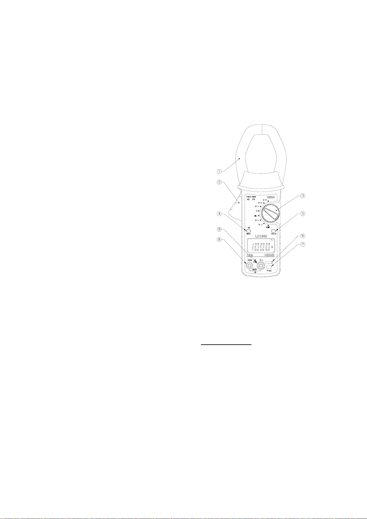
The main operating features of the instrument are as
follows. See Fig. 1.
(1) Clamp-on jaws for current m easurement
(2) Jaw opening lever
(3) Rotary switch for function selection
(4) Push button switch for MAX/
)))) selection.
MAX holds the maximum RMS value when in the
current or volts mode.
)))) selects continuity buzzer when in Ohms mode *
(5) Push button switch for di splay HOLD
(6) Sliding safety shutt er al l owing access to either the
test lead input term i nal s or the analogue output
port *
(7) V out - Analogue output port *
(8) and (9) - Test lead input terminal s *
Instrument Features
2. SPECIFICATION
Fig. 1
3
Page 5

2.1 Electrical data
(All accuracies s t ated at 23°C ± 1°C)
2.1.1 Current measurement
(DC, DCRMS*, ACRMS)
LH240
Measuring range ................ 0 - 200A DC or AC pk
Autorange facility 40A / 200A
Resolution ......................... 10mA in 40A range
100mA in 200A range
Accuracy I > 5A............... ±
1.3% rdg ± 3 digits
I < 5A .............. ± 0.2A
LH1040
Measuring range ................ 0 - 1000A DC or AC pk
Autorange facility ........ . ...... 400A / 1000A
Resolution ......................... 100mA in 400A range
1A in 1000A range
Accuracy I > 15A............. ± 1.3% rdg ± 3 digits
I < 15A ............ ± 0.5A
LH2040/LH2015
Measuring range ................ 0 - 2000A DC or AC pk
Autorange facility ........ . ...... 400A / 2000A
Resolution ......................... 100mA in 400A range
1A in 2000A range
Accuracy I > 25A............. ± 1.3% rdg ± 3 digits
I < 25A ............ ± 1.0A
Frequency range ................ DC and 15Hz to 1kHz in
DCRMS
15Hz to 1kHz in ACRMS
Frequency characteristics above 1kHz
Signal Amplitude ................ 3dB @ 5kHz
6dB @ 10kHz
Crest factor ........................ 6 maximum
Maximum overload ............ 10,000A or ACRMS x
frequency < 400,000
Amps ACRMS or DCRMS* offer AC or DC coupling of
the amps measurement respectively.
2.1.2 Max RMS Current
4
Page 6

This function is actuated by pressing MAX/ )))) when in
DC, DCRMS*, ACRMS Amps. No pol ari ty indication is
given for DC readings. Typical acqui sition time is
100ms
Accuracy .......................... ± 2% rdg ± 4 digits
Frequency Range............... DC and15 Hz to 1kHz in
DCRMS *
15 Hz to 1kHz in
ACRMS
Crest Factor........................ 6 maximum
2.1.3 Voltage measurement*
(DC,ACRMS)
Measuring range..... ............ 0-600V
Autorange Facility ............... 400V / 600V
Resolution.......................... 100mV in 400V range
1V in 600V range
Accuracy AC/DC............. ± 1% rdg ± 3 digits
AC < 20V......... ± 1V
Frequency Range............... DC in DC
15 Hz to 1kHz in
ACRMS
Maximum Overload ............ 1000V
Crest Factor ....................... 6 maximum
2.1.4 Max RMS Vo l tage *
This function is activated by pressing MAX/
)))) when in
DC or ACRMS. No polarity indicati on is given in DC.
Typical acquisition ti me is 100mS
Accuracy .......................... ± 2% rdg ± 4 digits
Frequency Range............... 15 Hz to 1kHz in
ACRMS
Crest Factor........................ 6 maximum
2.1.5 Diode Test *
Measurement of the voltage drop across a forward
biased diode.
Measuring range ..... ........... 0-2V
Resolution.......................... 1mV
Accuracy............................ ± 1% rdg ± 2 digits
Input protection ............. . ..... 600V
(DC or sinewave RMS)
2.1.6 Resistance Measurement *
Measuring range ..... ........... 0-4 kΩ
5
Page 7

Autorange Facility............... 400Ω/4kΩ
Resolution.......................... 100mΩ in 400Ω range
1Ω in 4kΩ range
Accuracy ........................... ± 1% rdg ± 3 digits
Input protection ............. . ..... 600V
(DC or sinewave RMS)
2.1.7 Continuity *
This function is actuated by pressing the MAX/
))))
button when in Ω measurem ent . The buzzer will sound
for values of resistance below ≈ 50Ω.
2.1.8 Analogue Output (Current Measurement) *
An analogue output of the meas ured current is
provided for use with oscilloscopes and recording
equipment. This can be ac cessed when the voltage
input terminals are bloc ked off by the sliding safety
cover. The output, either ins t antaneous or rms, is
switch selectable by a slider switch located in the
battery compartm ent.
Before removing the battery cover,
SAFETY WARNING
make sure that all external voltages are
disconnected from the instrument. For
certainty remove all leads.
Output voltage in all ranges:
LH240.................... 5mV/A
LH1040.................. 1mV/A
LH2040.................. 0.5mV/A
Accuracy............... ± 1.3% rdg ± 1mV (RMS)
± 1.3% rdg ± 7mV
(Instantaneous)
Frequency Range.. DC -1kHz Instantaneous
DC and 15Hz to 1kHz true RMS
Frequency characteristics above 1kHz.
Signal / Amplitude . 3dB @ 5kHz
6dB @ 10kHz
The analogue output adapter plugs into the f ront of the
instrument and the output i s obtained from a standard
BNC plug.
2.2 General Data
2.2.1 Display
6
Page 8

Display 4000 count 12mm high characters.
- + Low battery indicator
Pk Max RMS Amps or Volts
∼∼∼∼ AC
---- DC, DCRMS *
Diode *
kΩ Ohms *
)))) Continuity *
H Hold
2.2.2 Power Supply
Battery Type 9V Alkaline P P3 ,NEDA1604 or IEC
6LR61
Battery life typicall y 40 hours continuous operation.
H
2.2.3 Environmental
FOR INDOOR USE ONLY
Reference conditions. A l l accuracies stated at
23°C ± 1°C
Temperature coeff. of current ±0.1% of rdg per °C
Operating Temperature 0°C to 50°C (32°F to 122°F)
Maximum Relative Humidity 80% for temperatures up
to 31°C (87°F) decreasing linearly to 50% Relative
Humidity at 40°C (104°F)
Storage Temperature -20°C to +60°C (-4°F t o 140°F)
Maximum operating altitude 2000m.
2.2.4 Mechanical
Dimensions ........... Length 251mm / 9.88”
7
Page 9
Width 98mm / 3.86”
Depth 52mm / 2.05”
Weight................... 500g / 1.1 lbs.
Case Material ...... . . Bayblend T85MN
Jaw Opening ... ...... 55mm / 2.2”
Accessories........... Voltage probes *
Analogue Output lead *
Carrying case
Operators manual
Cleaning................ The unit can be cleaned
with an isopropanol
impregnated cloth.
Do not use abrasives or other
solvents.
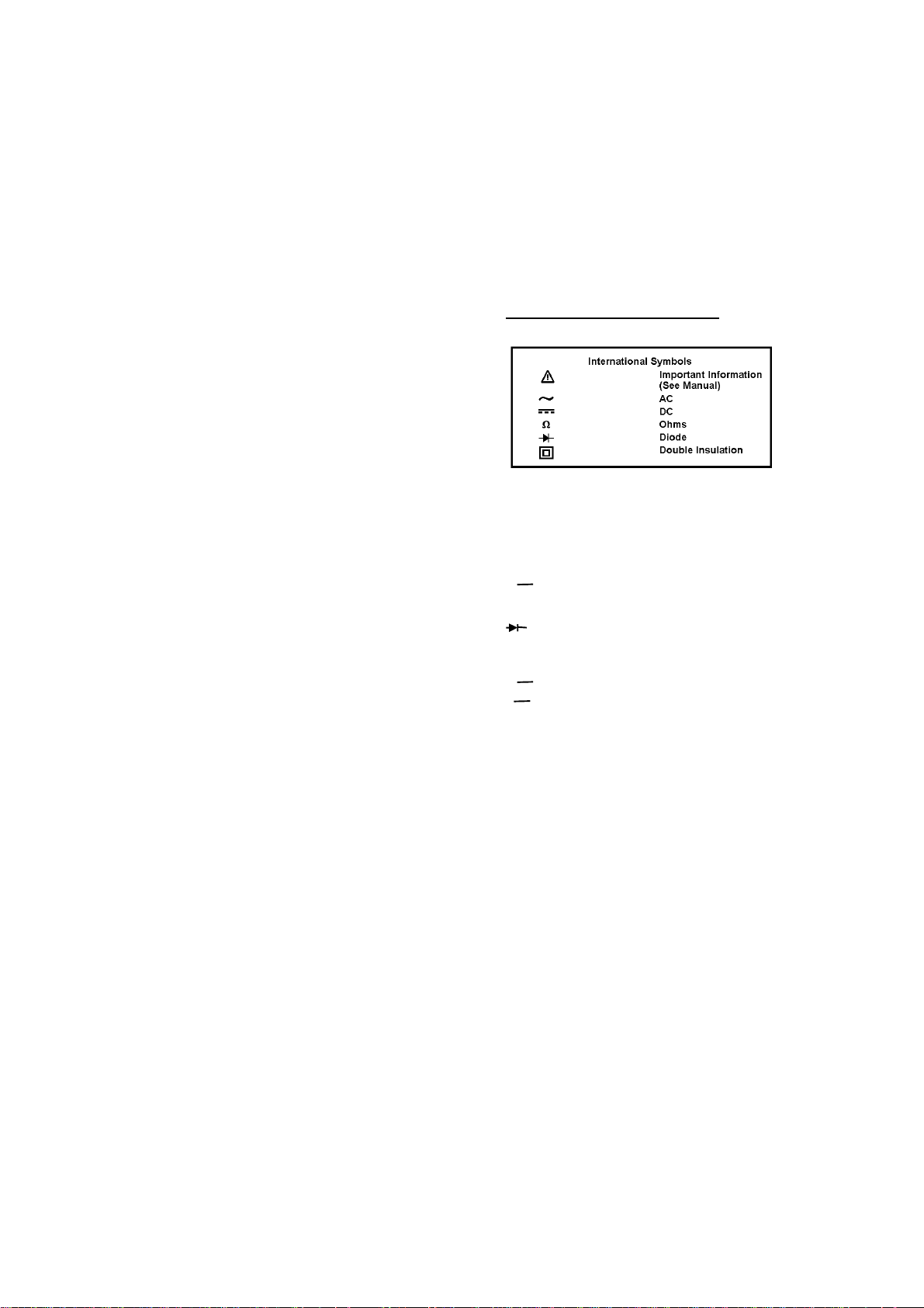
3. OPERATING INSTRUCTIONS
The instrument function is selected by a rotary switch
with the following positions :-
The instrument function is selected by a rotary switch with the
following positions :-
OFF Instrument off
V ---- Volts DC *
∼∼∼∼ Volts ACRMS *
V
Ω Ohms measurem ent *
∼∼∼∼ Amps ACRMS (AC Com ponent)
A
A ---- Amps DC (DC Component)
A
∼∼∼∼ Amps DCRMS (AC+DC) *
3.1 Measurement of AC or DC current
Diode measurement *
8
Page 10

• Remove any Voltage test leads from the
instrument.
• Move the rotary switch to Amps AC, DC or
DCRMS*.
• Wai t until the autozero operation has completed
and the display reads 00.00 (LH240), 000.0
(LH1040, LH2040, LH2015) to within ±3 digits.
• Press the tri gger to open the jaws and clamp them
around the current carrying conduct or as shown in
Fig. 2
• Read the display
• Use the HOLD button t o freeze the display.
• Use the
current.
• Note that the Amps autozero is initiated by the
movement of the rot ary switch from the Ω position
to the Amps m easurement positions. If, after a
high current measurem ent , the display does not
return to zero, then a re-autozero can be init i ated
by the movement of t he rotary switch into and out
of the Ω selecti on position for the LH40 series and
from OFF to Amps DC f or the LH2015.
3.2 Resistance Measurement *
• Insert the test leads into the sockets on t he front of
the instrument, t he red l ead to the VΩ terminal
and the black lead to the COM term i nal .
• Move the rotary switch to the Ω position.
• Apply the test l eads across the component whose
resistance is to be measured. Read the displayed
value.
• Use the HOLD button t o freeze the display. Use
the
The buzzer will sound for resistance
measurements below ≈ 50Ω.
))))/MAX button to measure the m ax RMS
))))/MAX button to select the continuity facility.
9
Page 11
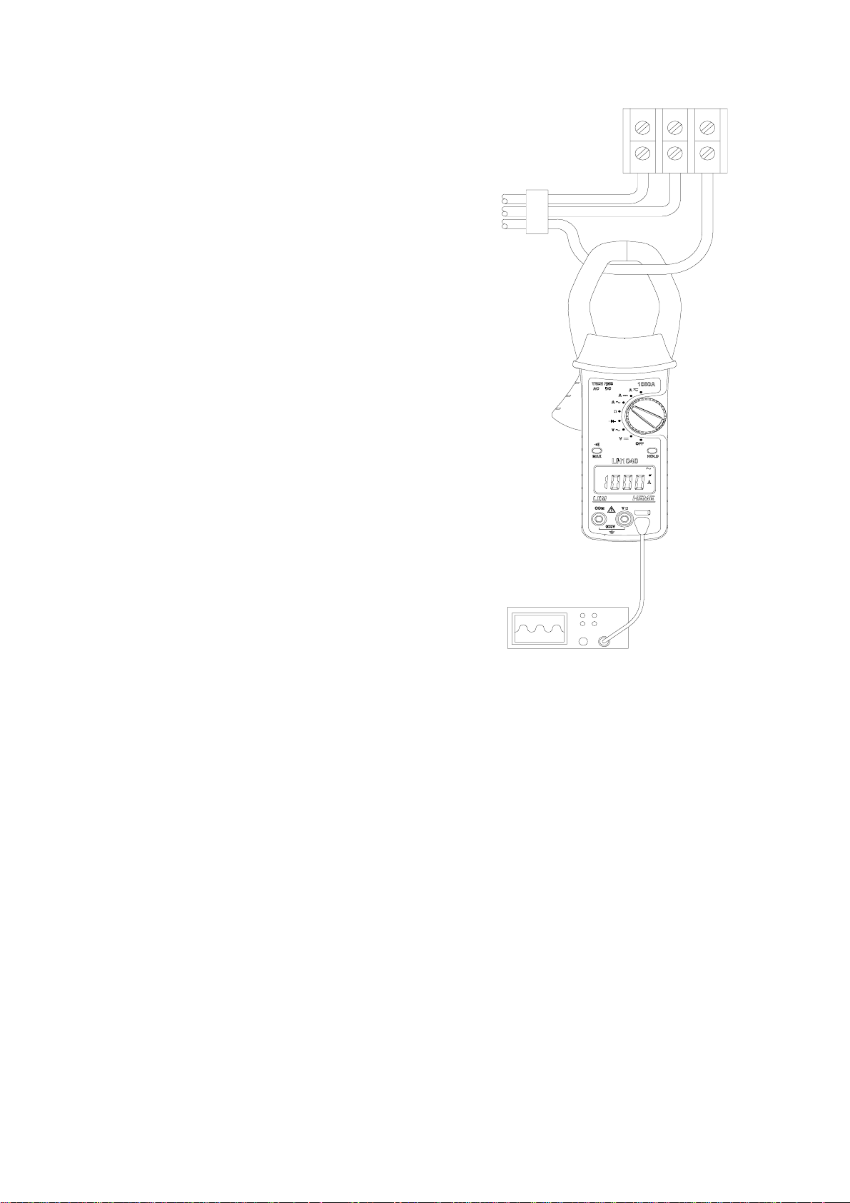
Fig. 2
Current Measurement
3.3 Measurement of AC or DC Voltage *
10
Page 12

To avoid possible electric shock and
damage to the instrument, do not attempt
to measure any voltage that might exceed
the maximum range of the instrument -
• Move the rotary switch t o the V DC or V AC
position.
• Insert the test leads into the sockets on t he front of
the instrument. Connect the RED lead to the VΩ
terminal and the black l ead to the COM terminal.
• Apply the test l eads to the circuit under test and
read the displayed voltage. See Fig. 3
• Use the HOLD button t o freeze the display.
• Use the
voltage
3.4 DiodeTest *
• Insert the test leads into the sockets on t he front of
the instrument, t he red l ead to the VΩ terminal
and the black lead to the COM term i nal .
• Move the rotary switch to the position.
• Apply the test l eads across the diode to be tested.
Read the displayed value.
• Use the HOLD button t o freeze the display.
3.5 Analogue Output *
))))/MAX button to measure the m ax RMS
SAFETY WARNING
600Vrms and 1kHz.
Before removing the battery cover,
make sure that all external voltages
are disconected from the instrument.
Measured current values can be output t o an
oscilloscope, chart rec order or ot her recording
instruments via t he anal ogue output lead.
The analogue output lead is rated at 300V RMS
maximum working voltage I E C1010 CAT III.
SAFETY WARNING
For certainty remove all leads.
11
Page 13
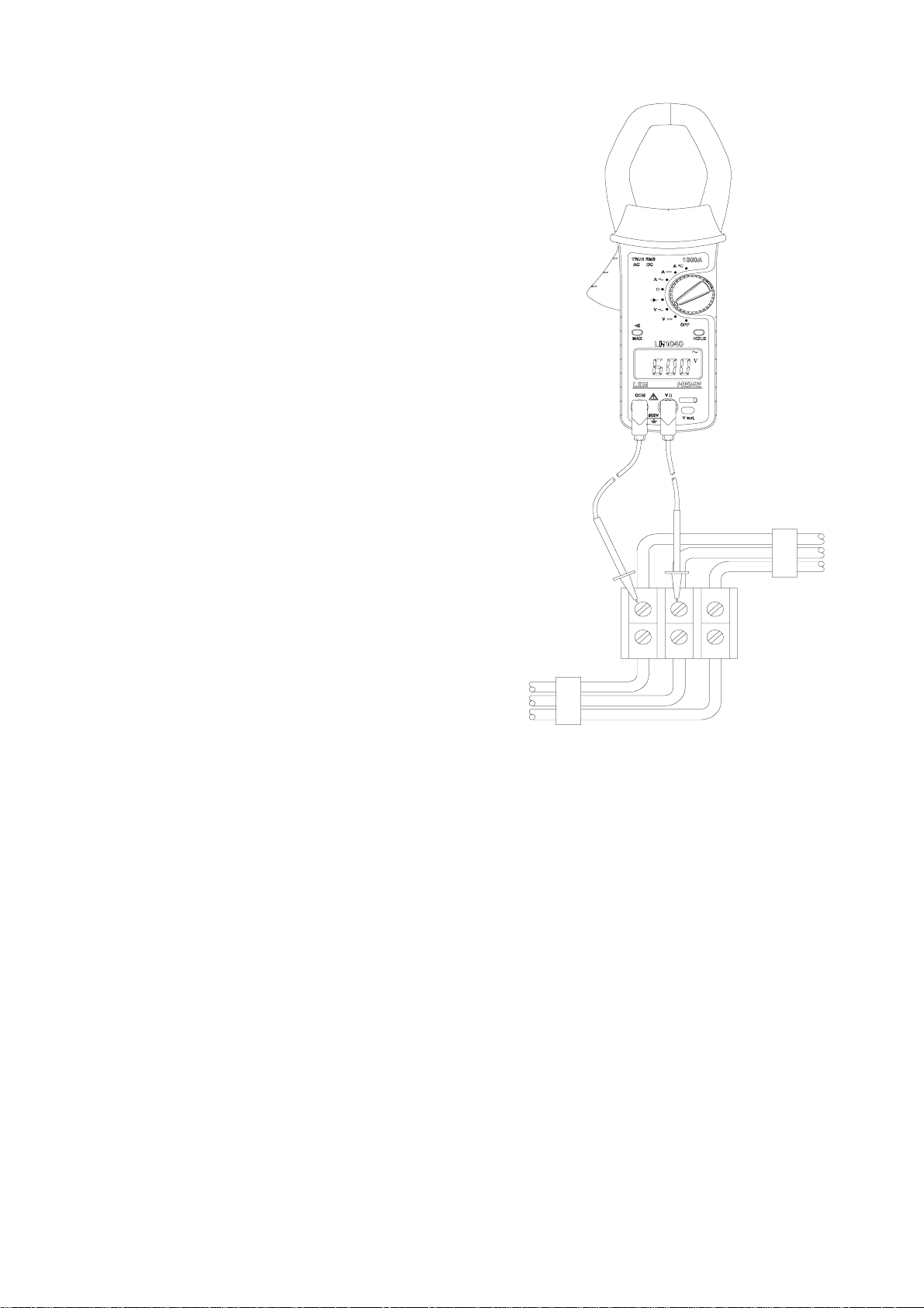
Fig. 3
Voltage Measurement
12
Page 14

If the analogue output lead is c onnected to a hand
held oscilloscope, then the m axim um working voltage
that may be connected to any of the other oscilloscope
inputs must be les s than 300V RMS to Earth.
• Located in the battery compartment is a slide
switch, which selects ei ther the instantaneous or
RMS analogue output. See “Battery
Replacement”, section 5, for details of gaining
access to the battery compartment. With the
battery removed from t he compartment, the
required output can be selected by moving the
switch to either the INST or RMS position. The
instantaneous output is i ntended for waveform
analysis, while the RMS signal i s a DC output
suitable for chart recorders.
• Replace the battery and cover.
• Slide the saf et y shutter at the bottom right hand
side of the instrum ent to the left, blocking off
access to the voltage i nput terminals and exposing
the analogue socket.
• Insert the analogue out put lead plug into the
socket on the lower right hand side of the
instrument.
• Insert the BNC pl ug, at the opposite end of the
Instantaneous/RMS lead, into an osc illoscope or
chart recorder.
• Select Amps ACRMS or DCRMS
4. SAFETY
The instrument has been desi gned t o comply with
IEC1010-2-032 Installation Category (Overvoltage
Category) III 600V Polluti on degree 2 and
UL 3111-1. The product range conforms with t he EEC
Low Voltage Directive 73/23/EEC and 93/ 68/EEC.
IEC 1010 is a safety st andard which has the following
features:
• Installat i on categories I to IV relate the maxim um
working voltage to overvoltage transients that can
be expected in the measuring environment. For
the LH range of instruments, 600V CATIII, the
maximum expected transients must not exceed
6kV peak.
• In a pollution degree 2 environment the internal
design of the instrum ent can cope with transient
conductivities due to condensation.
Users of this equipment and or their employees are
reminded that Health and Safety Legislation require
them to carry out valid ri sk assessments of al l
electrical work so as to i dentify potential sources of
electrical danger and risk of electrical injury such as
from inadvertent short circuits. Where the
assessments show that the risk is signific ant then the
use of fused test leads constructed in accordance with
the HSE guidance note GS38 ‘Electrical Test
Equipment for use by El ectricians’ is advised.
13
Page 15

Safe operation of the instrument is the
responsibility of the operator who must be suitably
qualified and/or authorised.
Maximum Safe Voltage
Current :- 600V MAXIMUM AC RMS or DC between
uninsulated conductor and ground and m aximum
frequency of 1kHz. This limitation applies to bare
conductors only.
Voltage:- 600V MAXIMUM AC RMS or DC between
live conductor and ground. 600V MAXIMUM AC RMS
or DC between VΩ and COM terminals and a
maximum frequency of 1kHz *.
Important Information
• The instrument is intended for indoor use only.
• Do not attem pt to take any measurement of
current or voltage higher than the m axim u m range
of the instrument.
• The unit is not hermetically sealed and should
NOT be brought into contact with surf ace water.
• Frequently inspect the test leads and the
instrument for damage. If the instrument is
physically damaged or does not function properly,
it should not be used.
USE ONLY SUITABLY RATED VOLTAGE TEST
LEADS TO IEC 1010-2-031. (600V CAT III Pollution
Degree 2).
5. BATTERY REPLACEMENT
Replacement with other than the specified battery will
invalidate the warranty.
Fit only Battery Type 9V Alk al i ne MN1604, IEC 6LR61
or equivalent.
- + will appear on the top row of the LCD display to
indicate that the m i ni mum operating battery voltage
has been reached.
Before removing the battery cover, make sure
that all external voltages are disconected from
the instrument. For certainty remove all leads.
To change the battery, see Fig. 4
• Switch off the i nstrument
• Undo the retaining sc rew on the bat tery cover and
lift the cover clear of the unit.
• Replace the used battery. Ensure the battery
cover is replaced and the lock i ng screw tightened,
before further use.
SAFETY WARNING
14
Page 16

Fig. 4
Battery Replacement
6. WARRANTY
Your LEM HEME clamp on multi meter is guaranteed
for one year from the date of purchase against
defective material or workmanship. If the meter fails
during the warranty period, we shall at our disc retion,
repair or replace it with a new or reconditioned unit
provided we are satisfied that the failure is due to
defective material or workm anship. To make a claim
under warranty, the meter should be returned to us,
postage prepaid, with a description of the defect . The
use of a battery, other than that specified invalidates
this warranty.
Goods alleged by the buyer to be defect ive shall not
form the subject of any claim fo r injury, loss, dam age,
or any expense howsoever incurred whether arising
directly or indirectly from such alleged defects other
than death or personal injury result ing from t he s eller‘ s
negligence.
No condition is made or to be implied nor is any
warranty given or to be implied as t o t he lif e or wear of
goods supplied or that they will be suitable for any
particular purpose or for use under spec ific condi tions,
notwithstanding that such purpose or conditions may
be made known to the seller.
7. OTHER PRODUCTS
15
Page 17

The LEM group offers a wide range of non-invasive
transducers, probes and instrumentation for the
measurement and analysis of current, voltage and
power.
Since the introduction of the world’s first digital
AC/DC clamp-on amm eter in 1982, LEM HEME has
continued to provide innovative test and
measurement solutions encompassing current
measurement from 5mA to 2000A.
LEM HEME policy is one of cont i nuous product
improvement and the company reserves the right
to revise the above specifi cations without notice.
* LH40 series only (LH240, LH1040, LH2040)
16
 Loading...