

Page 1
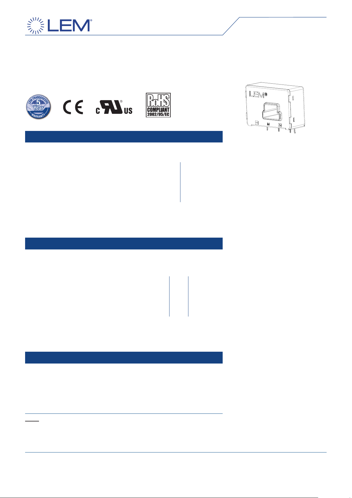
Current Transducer LA 200-P
For the electronic measurement of currents: DC, AC, pulsed...,
with galvanic isolation between the primary circuit (high power) and
the secondary circuit (electronic circuit).
16044
Electrical data
IPN = 200 A
IPN Primary nominal current rms 200 A
IPM Primary current, measuring range 0 .. ± 300 A
RM Measuring resistance @ TA = 70°C TA = 85°C
R
with ± 12 V @ ± 200 A
@ ± 250 A
with ± 15 V @ ± 200 A
@ ± 300 A
ISN Secondary nominal current rms 100 mA
KN Conversion ratio 1 : 2000
VC Supply voltage (± 5 %) ± 12 .. 15 V
I
Current consumption 16 (@ ± 15 V) + IS mA
C
0 30 0 26 Ω
max
0 8 0 4 Ω
max
0 60 0 56 Ω
max
0 12 0 8 Ω
max
M min RM max RM min RM max
Accuracy - Dynamic performance data
X Accuracy @ IPN , TA = 25°C @ ± 15 V (± 5 %) ± 0.40 %
@ ± 12 .. 15 V (± 5 %) ± 0.65 %
ε
Linearity error < 0.15 %
L
Typ Max
IO Offset current @ IP = 0, TA = 25°C ± 0.20 mA
IOM Magnetic offset current 1) @ IP = 0 and specied RM,
after an overload of 3 x IPN ± 0.25 mA
IOT Temperature variation of IO 0°C .. + 70°C ± 0.10 ± 0.25 mA
- 40°C .. + 85°C ± 0.15 ± 0.55 mA
tra Reaction time to 10 % of IPN step < 500 ns
tr Response time 2) 3) to 90 % of IPN step < 1 µs
di/dt di/dt accurately followed 3) > 200 A/µs
BW Frequency bandwidth (- 1 dB) DC .. 100 kHz
General data
TA Ambient operating temperature - 40 .. + 85 °C
TS Ambient storage temperature - 40 .. + 90 °C
RS Secondary coil resistance @ TA = 70°C 76 Ω
TA = 85°C 80 Ω
m Mass 40 g
Standards EN 50178: 1997
Features
Closed loop (compensated) ●
current transducer using the Hall
effect
Printed circuit board mounting ●
Isolated plastic case recognized ●
according to UL 94-V0.
Advantages
Excellent accuracy ●
Very good linearity ●
Low temperature drift ●
Optimized response time ●
Wide frequency bandwidth ●
No insertion losses ●
High immunity to external ●
interference
Current overload capability. ●
Applications
AC variable speed drives and ●
servo motor drives
Static converters for DC motor ●
drives
Battery supplied applications ●
Uninterruptible Power Supplies ●
(UPS)
Switched Mode Power Supplies ●
(SMPS)
Power supplies for welding ●
applications.
Application domain
Industrial. ●
Notes: 1) The result of the coercive eld of the magnetic circuit
2)
the primary conductor is above the top of the transducer.
090508/15
With a di/dt of 100 A/µs
3)
The primary conductor is best lling the through-hole and/or the return of
LEM reserves the right to carry out modications on its transducers, in order to improve them, without prior notice.
Page 1/3
www.lem.com
Page 2
Current Transducer LA 200-P
dCp, dCI,
Rated isolation voltage
Nominal voltage
Single isolation
600 V
600 V
Reinforced isolation
300 V
300 V
Isolation characteristics
Vd Rms voltage for AC isolation test, 50 Hz, 1 min 3 kV
Impulse withstand voltage 1.2/50 µs 7 kV
V
w
Ve Partial discharge extinction voltage rms @ 10 pc > 1.8 kV
Min
dCp Creepage distance 6.7 mm
dCI Clearance distance 6.7 mm
CTI Comparative Tracking Index (group IIIa) 175
Applications examples
According to EN 50178 and IEC 61010-1 standards and following conditions:
Over voltage category OV 3 ●
Pollution degree PD2 ●
Non-uniform eld ●
EN 50178 IEC 61010-1
V
w
Safety
This transducer must be used in electric/electronic equipment with respect
to applicable standards and safety requirements in accordance with the
manufacturer’s operating instructions.
Caution, risk of electrical shock
When operating the transducer, certain parts of the module can carry hazardous
voltage (eg. primary busbar, power supply).
Ignoring this warning can lead to injury and/or cause serious damage.
This transducer is a build-in device, whose conducting parts must be inaccessible
after installation.
A protective housing or additional shield could be used.
Main supply must be able to be disconnected.
090508/15
LEM reserves the right to carry out modications on its transducers, in order to improve them, without prior notice.
Page 2/3
www.lem.com
Page 3
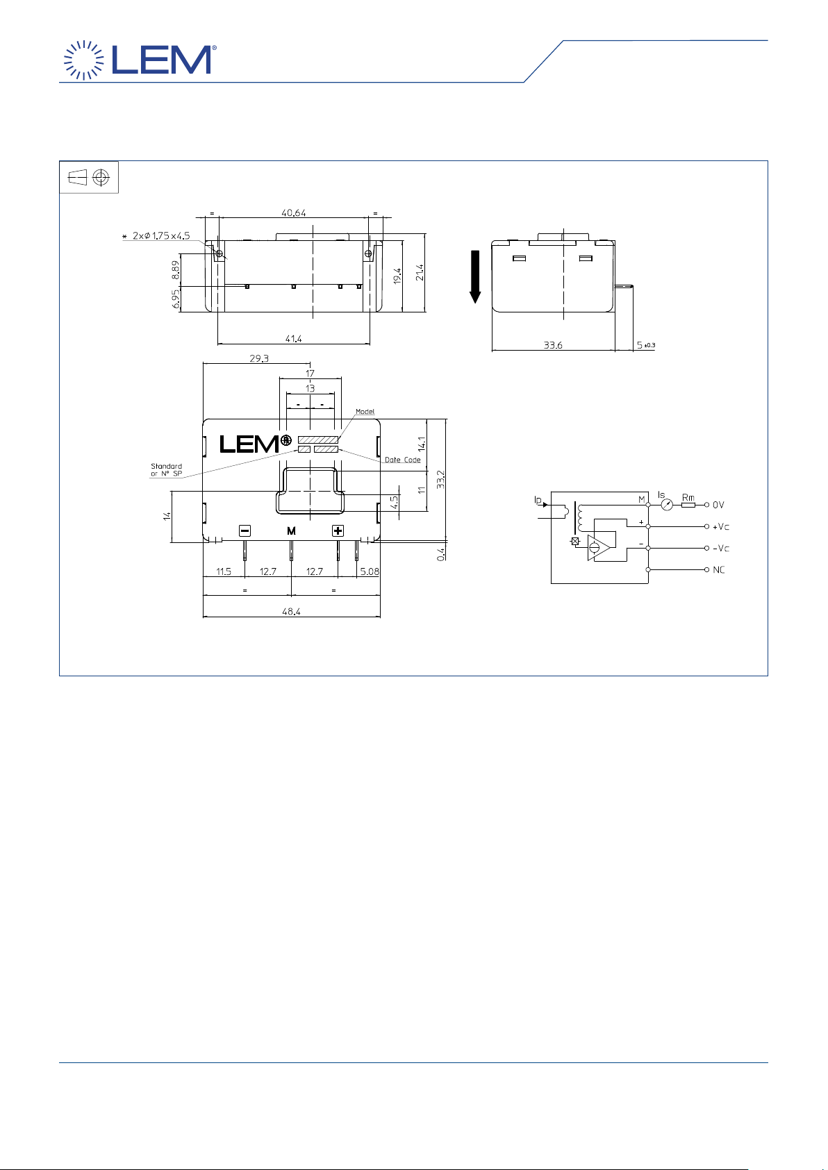
Dimensions LA 200-P (in mm. 1 mm = 0.0394 inch)
Bottom view Left view
Front view
Mechanical characteristics
General tolerance ± 0.2 mm ●
Primary through-hole 17 x 11 mm ●
Fastening & connection of secondary 4 pins ●
0.63 x 0.56 mm
Recommended PCB hole 0.9 mm ●
Supplementary fastening 2 holes Ø 1.75 mm ●
Recommended PCB hole 2.4 mm
Recommended screws PT KA 22 x 6.
Connection
Remarks
I ●S is positive when IP ows in the direction of the arrow.
Temperature of the primary conductor should not exceed ●
90°C.
Dynamic performances (di/dt and response time) are best ●
with a primary bar in low position in the through-hole.
In order to achieve the best magnetic coupling, the ●
primary windings have to be wound over the top edge of
the device.
This is a standard model. For different versions (supply ●
voltages, turns ratios, unidirectional measurements...),
please contact us.
090508/15
LEM reserves the right to carry out modications on its transducers, in order to improve them, without prior notice.
Page 3/3
www.lem.com
 Loading...