

Page 1

Page 2

IMPORTANT SAFETY INSTRUCTIONS
INSTRUCTIONS PERTAINING TO A RISK OF FIRE, ELECTRIC SHOCK OR INJURY TO PERSONS
WARNING - When using electric products, basic precautions should always be followed, including the
following:
1. Read all the SAFETY INSTRUCTIONS before using the product.
2. To reduce the risk of injury, close supervision is necessary when the product is used near children.
3. Do not use this product near water - for example, near a bathtub, washbowl, kitchen sink, in a wet
basement or near a swimming poor or the like.
4. This product in combination may be capable of producing sound levels that could cause
permanent hearing loss. Do not operate for a long period of time at high volume level or at a level
that is uncomfortable. If you experience any hearing loss or ringing in the ears, you should consult an
audiologist.
5. This product should be located so that its location or position does not interfere with its proper
ventilation.
6. This product should be located away from heat sources such as radiators, heat registers or other
products that produce heat.
7. The product should be connected to a power supply only of the type described on the operating
instructions or as marked on the product.
8. This product may be equipped with a polarized line plug (one blade wider than the other). This is a
safety feature. If you are unable to insert the plug into the outlet, contact an electrician to replace your
obsolete outlet. Do not defeat the safety purpose of the plug.
9. The power-supply cord of the product should be unplugged from the outlet when left unused for a
long period of time. When unplugging the power-supply cord, do not pull on the cord, but grasp it by
the plug.
10. Care should be taken so that object do not fall and liquid are not spilled into the enclosure through
openings.
11. The product should be serviced by qualifi ed service personnel when:
A. The power-supply cord or the plug has been damaged; or
B. Objects have fallen, or liquid has been spilled into the product; or
C. The product has been exposed to rain; or
D. The product does not appear to operate normally or exhibits a marked change in performance; or
E. The product has been dropped or the enclosure damaged.
12. Do not attempt to service the product beyond that described in the user-maintenance instructions.
All other servicing should be referred to qualifi ed service personnel.
13. WARNING - Do not place objects on the product's power cord or place it in a position where anyone
could trip over, walk on or roll anything over it. Do not allow the product to rest on or to be installed over
power cords of any type. Improper installations of this type create the possibility of fi re hazard and/or
personal injury.
SAVE THESE INSTRUCTIONS
The lightning flash with arrowhead symbol within an
equilateral triangle is intended to alert the user to the
presence of uninsulated "dangerous voltage" within the
product's enclosure, that may be of sufficient magnitude to
constitute a risk of electric shock to persons.
The exclamation point within an equilateral triangle is
intended to alert the user to the presence of important
operating and maintenance (servicing) instructions in the
literature accompanying the appliance.
Page 3

3
hurricane active
1. Introduzione
Congratulazioni per l’acquisto del sistema di diffusione
HURRICANE ACTIVE series! Per un impiego corretto
del sistema seguite le istruzioni riportate in questo
manuale. Buon divertimento e buon lavoro!
2. Sommario
3. Norme di Installazione e Uso . . . . . . . . . 3
1. La protezione e la manutenzione . . . . . . . . . . . . 3
2. Collegamenti . . . . . . . . . . . . . . . . . . . . . . . . . . . 3
3. I cavi di collegamento. . . . . . . . . . . . . . . . . . . . . 3
4. La serie HURRICANE ACTIVE. . . . . . . . . 3
5. Installazione e collegamenti. . . . . . . . . . 3
1. Installazione . . . . . . . . . . . . . . . . . . . . . . . . . . . . 3
2. Collegamenti . . . . . . . . . . . . . . . . . . . . . . . . . . 3
3. Sistemi SUB + SATELLITE. . . . . . . . . . . . . . . . . 3
6. Pannello connessioni . . . . . . . . . . . . . . . 4
7. Specifi che tecniche. . . . . . . . . . . . . . . . . 4
3. Norme di Installazione e Uso
1. La protezione e la manutenzione.
Evitate di collocare i diffusori in vicinanza di forti fonti
di calore e di esporli direttamente alla luce solare,
alla pioggia, all’umidità, alla polvere o ad intense
vibrazioni. Lasciate l’apposita griglia di protezione
sempre applicata ai diffusori. In caso di avaria non
aprite il diffusore, ma rivolgetevi al più vicino Centro di
Assistenza GENERALMUSIC.
2. Prevenzione di possibili disturbi.
Collegando gli apparati del vostro impianto audio, fate
attenzione ai cosiddetti “loop di massa” che potrebbero
causare ronzii: in caso di disturbi, provate ad agire
sullo switch SHIELD posto sul pannello controlli del
diffusore.
3. Collegamenti
Prima di collegare i diffusori alla presa di corrente,
accertatevi che la tensione di rete corrisponda a
quella indicata sul retro dell’apparato (è accettata
unatolleranza fino a ±10%). Collegate il cavo di
alimentazione al diffusore sempre prima di accenderlo e
rimuovete il cavo sempre dopo aver spento il diffusore.
Per evitare pericolosi picchi di segnale effettuate i
collegamenti con altri apparati sempre a diffusore
spento e accendete sempre prima il mixer e poi il
diffusore.
4. I cavi di collegamento
Per il collegamento dei diffusori al mixer accertatevi
di utilizzare sempre e solo cavi di segnale schermati
costituiti da due fi li più una calza che funge da schermo.
L’utilizzo di cavi non schermati potrebbe determinare
l’insorgere di fastidiosi ronzii e rumori di fondo.
Verifi cate periodicamente che i cavi impiegati siano in
buono stato, con le connessioni realizzate nel modo
corretto e con tutti i contatti in perfetta effi cienza, in
modo da evitare inconvenienti come falsi contatti,
rumori di massa, scariche, ecc.
4. La serie HURRICANE ACTIVE (fi g. 1)
La serie HURRICANE ACTIVE è una linea di diffusori
amplifi cati con cabinet in truciolare di pioppo. La serie
si compone di 9 modelli.
- H150A: utilizza un driver a compressione da 1” su
tromba EWT ed un woofer da 10”. L'amplificatore
interno ha una potenza di 150W EIA.
- H200A: utilizza un driver a compressione da 1” su
tromba EWT ed un woofer da 12”. L'amplificatore
interno ha una potenza di 200W EIA.
- H300A: utilizza un driver a compressione da 1” su
tromba EWT ed un woofer da 15”. L'amplificatore
interno ha una potenza di 250+50W EIA.
- H350A: utilizza un super-tweeter ad ampia dispersione
da 1.5”, un altoparlante midrange da 8” ed un woofer da
15”. L'amplifi catore interno ha una potenza di 270+80W
EIA.
- H350SA: si tratta di un sub-woofer che utilizza un
woofer da 15”. L'amplifi catore interno ha una potenza
di 350W EIA.
- H400SA: si tratta di un sub-woofer che utilizza un
woofer da 18”. L'amplifi catore interno ha una potenza
di 400W EIA.
H100MA: si tratta di un monitor da palco con un
altoparlante full range da 8”. L'amplifi catore interno ha
una potenza di 100W EIA.
- H200MA: si tratta di un monitor da palco con un driver
a compressione da 1” su tromba EWT ed un woofer
da 12”. L'amplifi catore interno ha una potenza di 200W
EIA.
- H300MA: si tratta di un monitor da palco con un driver
a compressione da 1” su tromba EWT ed un woofer da
15”. L'amplifi catore interno ha una potenza di 250+50W
EIA.
I modelli con amplificatore singolo sono dotati
di crossover passivo realizzato con componenti
selezionati, di un sofi sticato circuito elettronico per la
protezione del driver contro i sovraccarichi di potenza e
di un sistema di anti-clipping.
I modelli con bi-amplifi cazione sono dotati di crossover
attivo ad elevata precisione e di limiter indipendenti per
la parte alta e la parte bassa.
I due sub-woofer, infine sono dotati di connessioni
stereo e di crossover attivo a frequenza variabile.
Page 4

4
hurricane active
5. Installazione e collegamenti
1. Installazione
Tutti i modelli della serie HURRICANE ACTIVE sono
dotati di un adattatore in metallo per l’installazione
su supporto standard per diffusori. I due sub-woofer
possiedono un adattatore che consente l'accoppiamento
con il satellite utilizzando un supporto telescopico (LEM
SC-31).
2. Collegamenti
Gli ingressi dei diffusori HURRICANE ACTIVE possono
essere utilizzati con segnali di linea provenienti da
apparecchiature con uscite ad alto livello. Per il
collegamento utilizzate cavi di segnale BILANCIATI
con connettore XLR o JACK (fi g. 2).
Il livello del segnale in ingresso può essere regolato
tramite il controllo VOL. Se utilizzate apparecchiature
con un livello di uscita particolarmente alto, potete
ruotare il potenziometro verso sinistra riducendo il
guadagno fi no alla chiusura completa.
Per rilanciare il segnale verso un secondo diffusore
utilizzate il connettore LINK (fi g. 3).
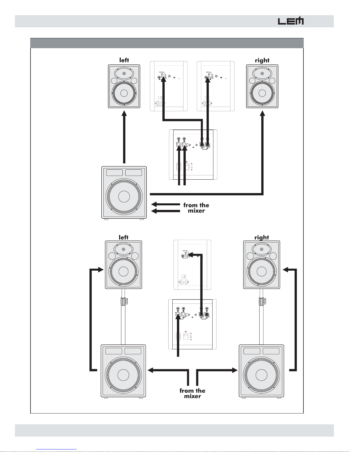
3. Sistemi SUB + SATELLITE (fi g. 4)
Nella tabella seguente sono riportate le combinazioni
consigliate sub-woofer + satellite per i diffusori della
serie HURRICANE ACTIVE. Nella fi gura no. 4 trovate
gli schemi di collegamento per l'utilizzo dei sub-woofer
in confi gurazione singola (single) o doppia (double).
a) 1xH350SA + 2xH150A: potenza totale
650W (conf. singola)
b) 2xH350SA + 2xH150A: potenza totale
1000W (conf. doppia)
c) 2xH350SA + 2xH200A: potenza totale
1100W (conf. doppia)
d) 1xH400SA + 2xH200A: potenza totale
800W (conf. singola)
e) 2xH400SA + 2xH200A: potenza totale
1200W (conf. doppia)
f) 2xH400SA + 2xH300A: potenza totale
1600W (conf. doppia)
6. Pannello connessioni (fi g. 3)
1. Connettori XLR + JACK collegati in parallelo
(LINK) per l’ingresso ed il rilancio del segnale.
2. Connettori STEREO XLR-F + JACK collegati in
parallelo (LINK) per l’ingresso ed il rilancio del
segnale (solo H350SA e H400SA).
3. Connettori STEREO XLR-M + JACK collegati in
parallelo (LINK) per il collegamento dei satelliti
(solo H350SA e H400SA).
4. Controllo per la selezione della frequenza di taglio
del crossover interno da 80 a 320Hz (solo H350SA e
H400SA) .
5. LED SIGNAL/COMP (solo su H350SA e H400SA):
segnala la presenza di segnale (VERDE) o
l’intervento del compressore (ROSSO).
6. Controllo di livello del segnale inviato all’amplifi catore
interno.
7. Controllo di separazione della massa elettrica dalla
massa del telaio.
8. Interruttore di accensione/spegnimento con LED di
segnalazione.
9. Presa per il cavo di alimentazione.
Page 5

5
hurricane active
7. Specifi che Tecniche
H150A H200A H300A H350A H350SA H400SA H100MA H200MA H300MA
Alti
Super-tweeter
da 1.5"
Medi
Midrange da 8"
Bassi
Woofer da 10" Woofer da 12" Woofer da 15" Woofer da 15" Woofer da 15" Woofer da 18" Full-range da 8" Woofer da 12" Woofer da 15"
Costruzione
Dimensioni
mm (LxAxP)
340x460x285 390x508x325 455x580x405 455x790x405 475x555x520 625x540x545 305x395x275 390x508x325 455x580x405
Peso
kg
18,5 22 27,5 33,5 35,6 43 13 20,5 27
Ingresso
sensibilità
im
p
edenza
Crossover
passivo
3.5Khz
12/18dB/ott.
3.5Khz
12/18dB/ott.
6Khz
12/12dB/ott.
3.5Khz
12/18dB/ott.
Crossover
attivo
3.5Khz
12/18dB/ott.
600Hz
18/18dB/ott.
80-320Hz
12dB/ott.
80-320Hz
12dB/ott.
3.5Khz
12/18dB/ott.
Potenza di uscita
EIA (1kHz, THD 1%)
W Alt
i
W Bass
i
150 200
50
250
80
270
350 400 100 200
50
250
Distorsione
%
Controlli
Connessioni
Alimentazione
Risposta in
frequenza
Hz (-10dB) 60-20Khz 55-20Khz 48-20Khz 38-25Khz 38-300 32-300 65-20Khz 55-20Khz 48-20Khz
Sensibilità
MAX SPL
continuo
117dB 120dB 123dB 122dB 121dB 122dB 114dB 120dB 123dB
Dispersione
°
60x40 60x40 60x40 120x40 90x90 60x40 60x40
HURRICANE ACTIVE SERIES • SPECIFICHE TECNICHE
SPECIFICHE dell'AMPLIFICATORE
SPECIFICHE del SISTEMA
vedi etichetta sull'apparato
<0.02
Volume - SHIELD Volume - SHIELD - Xover freq. Volume - SHIELD
1 x XLR-F + 1 x JACK in parallelo 1 x XLR-F + 1 x JACK in parallelo
2 x JACK + XLR-F (in)
2 x JACK + XLR-M (out)
Truciolare di pioppo ad alta densità con moquette grigio antracite anti-strappo - Griglia metallica di protezione - 1/2 maniglie per il trasporto -
SPECIFICHE del DIFFUSORE
Driver da 1" con EWT horn
0 dB (nominale)
20 kOhms (bilanciato)
Componenti
Driver da 1" con EWT horn
Page 6

6
hurricane active
1. Introductions
Congratulations for having chosen the HURRICANE
ACTIVE series of loudspeaker system!
To make the best use of the system, please read this
manual thoroughly before operating the equipment.
2. Contents
3. Instructions for use and installation . . . 5
1. Protection and maintenance. . . . . . . . . . . . . . . . 5
2. Connections . . . . . . . . . . . . . . . . . . . . . . . . . . . . 5
3. Connector cables . . . . . . . . . . . . . . . . . . . . . . . . 5
4. The HURRICANE ACTIVE series. . . . . . . 5
5. Installation and connections . . . . . . . . . 5
1. Installation . . . . . . . . . . . . . . . . . . . . . . . . . . . . . 5
2. Connections . . . . . . . . . . . . . . . . . . . . . . . . . . . . 5
3. SUB + SAT systems . . . . . . . . . . . . . . . . . . . . . . 5
6. Connection panel . . . . . . . . . . . . . . . . . . 6
7. Technical specifi cations . . . . . . . . . . . . . 6
3. Instructions for use and installation
1. Protection and maintenance.
To avoid jeopardizing correct operation, it is best not
to position the enclosure for long periods in exposed
places (damp, high temperature, etc.), in dusty
environments or those subject to strong vibrations.
On this subject, it’s advisable to always leave the
protective grid mounted on the enclosure. In the event
of breakdown, do not open the enclosure, but contact
the nearest GENERALMUSIC Service Centre.
2. Prevention of possible interference.
Avoid installing your equipment in the vicinity of
radios, televisions, etc., since this could cause noisy
disturbance. When connecting other equipment to
your sound system, pay close attention to so-called
earthloops, which can cause hum: in the event of
interference, try using the SHIELD switch on the
enclosure’s control panel.
3. Connections.
Before connecting the enclosure to the mains supply,
make certain that the current corresponds with that
indicated on the rear of the unit (there is an allowance
of ±10%). Always connect the power cable to the
enclosure before switching on the enclosure and
always remove it after having switched off. Remember
to always connect or disconnect other equipment with
the enclosure off and to always switch on the mixer fi rst,
then the enclosure: in this manner, annoying and often
dangerous peaks are avoided.
4. Connector cables (fi g. 4).
When connecting the enclosures to the mixer, make
certain to always use only screened signal cables
made up of two wires plus a braid/screen: the use
of unscreened cables could in fact probably cause
annoying hum and noise. Check periodically that your
cables are in good condition, correctly wired and with
perfectly effi cient contacts: in fact many problems and
drawbacks (false contacts, ground hum, crackles,
etc.) are caused by the use of unsuitable or damaged
cables.
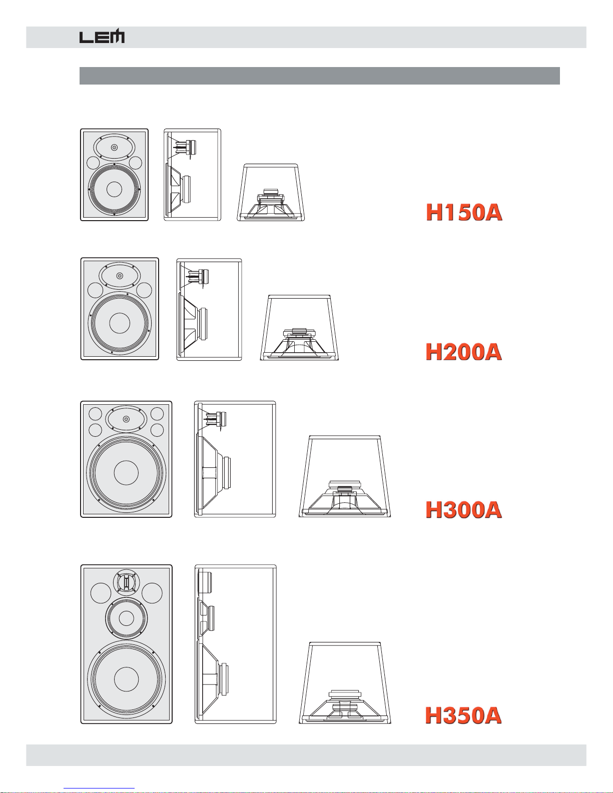
4. The HURRICANE ACTIVE series (fi g. 1)
The HURRICANE series is range of active loudspeaker
systems hosted in poplar chipboard cabinets. The series
includes 9 different models.
- H150A: it is fi tted with a 1” compression driver on EWT
horn and with a 10” woofer. The built-in power amplifi er
has an output power of 150W EIA.
- H200A: it is fi tted with a 1” compression driver on EWT
horn and with a 12” woofer. The built-in power amplifi er
has an output power of 200W EIA.
- H300A: it is fi tted with a 1” compression driver on EWT
horn and with a 15” woofer. The built-in power amplifi er
has an output power of 250+50W EIA.
- H350A: it is fi tted with a 1.5” wide-dispersion supertweeter, an 8" midrange and a 15” woofer. The built-in
power amplifi er has an output power of 270+80W EIA.
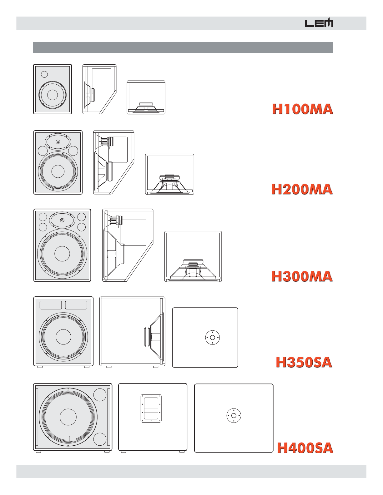
- H350SA: it is a sub-woofer system fi tted with a 15”
woofer. The built-in power amplifi er has an output power
of 350W EIA.
- H400SA: it is a sub-woofer system fi tted with a 18”
woofer. The built-in power amplifi er has an output power
of 400W EIA.
- H100MA: it is a stage monitor fi tted with a 8” full-range
woofer. The built-in power amplifi er has an output power
of 100W EIA.
- H200MA: it is a stage monitor fitted with a 1”
compression driver on EWT horn and with a 12” woofer.
The built-in power amplifi er has an output power of
200W EIA.
- H300MA: it is a stage monitor fitted with a 1”
compression driver on EWT horn and with a 15” woofer.
The built-in power amplifi er has an output power of
250+50W EIA.
The models with single power amplifi er are equipped
with carefully engineered passive crossover, with a
sophisticated active circuit for the protection of the
drivers against power overloading and with an anticlipping system.
The models with bi-amp power amplifi ers are fi tted with
high-precision active crossover and independent limiters
for the high and the low section.
Finally, the two sub-woofer systems are equipped with
stereo connections and with frequency selectable active
crossover fi lter.
Page 7

7
hurricane active
5. Installation and connections
1. Installation
All the HURRICANE ACTIVE series models are fi tted
with an adapter for the installation on a standard
loudspeaker stand. The two sub-woofer systems have
an adapter on the top panel for the installation of a
satellite using a telescopic pole (LEM SC-31)
2. Connections
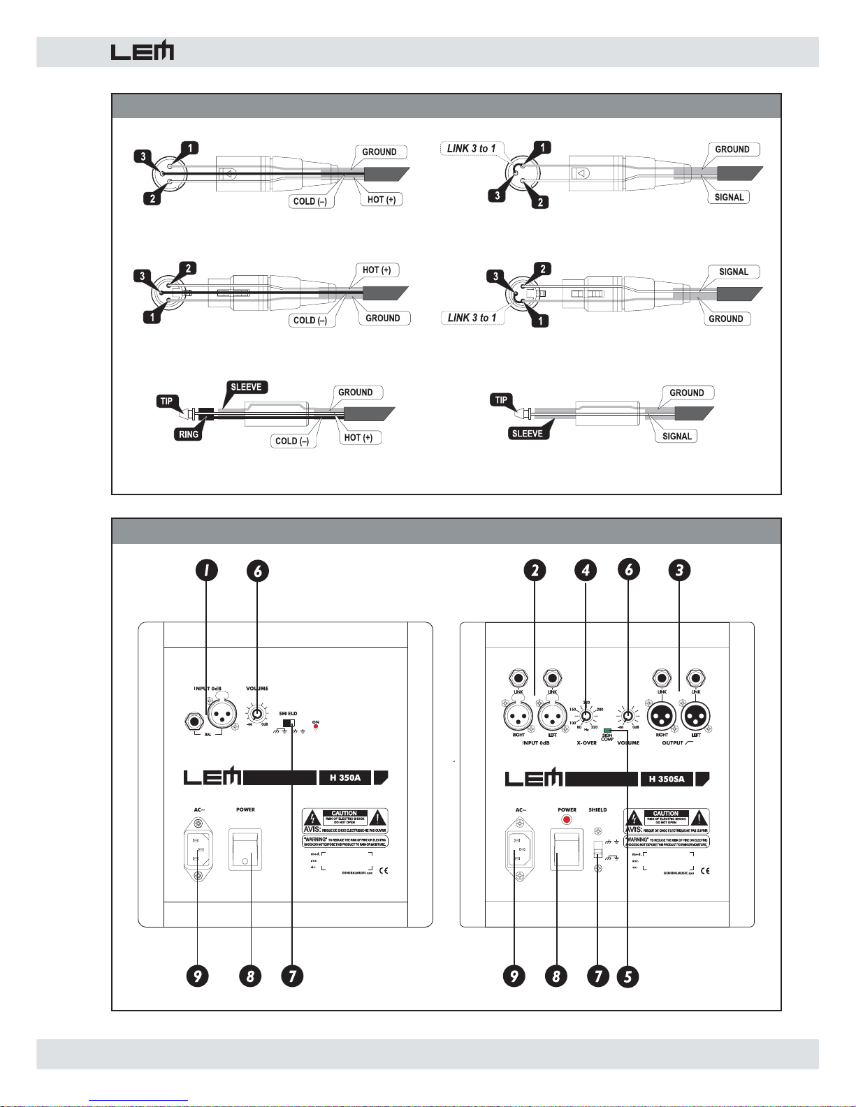
The inputs of the HURRICANE ACTIVE loudspeaker
systems can be used with line signals coming from
devices with high-level outputs (see fi g. 2). For the
connection, use BALANCED signal cables with XLR or
JACK connector.
The input level of the incoming signal can be set using
the VOL control. If you are using devices with a too high
output level, you can reduce the input gain turning the
control counterclockwise.
If you need to send the same signal to a second
loudspeaker system you can use the XLR-M LINK
connector (fi g. 3).
3. SUB + SATELLITE systems (see fi g. 4)
In the following table you can fi nd the suggested subwoofer + satellite setups for the HURRICANE ACTIVE
loudspeaker systems. In the fi g. no. 4 you can fi nd also
the connection diagram for the use of the sub-woofers
in single or double confi guration.
a) 1xH350SA + 2xH150A: total power
650W (single confi guration)
b) 2xH350SA + 2xH150A: total power
1000W (double confi guration)
c) 2xH350SA + 2xH200A: total power
1100W (double confi guration)
d) 1xH400SA + 2xH200A: total power
800W (single confi guration)
e) 2xH400SA + 2xH200A: total power
1200W (double confi guration)
f) 2xH400SA + 2xH300A: total power
1600W (double confi guration)
6. Connection panel (fi g. 3)
1. XLR-F + JACK sockets connected in parallel for the
signal input and linking.
2. XLR-F + JACK sockets connected in parallel for
the signal input and linking (only H350SA and
H400SA).
3. XLR-M + JACK sockets connected in parallel for
the connection of the satellites (only H350SA and
H400SA).
4. Control for selecting the crossover frequency from
80Hz to 320Hz (only H350SA and H400SA).
5. SIGN/COMP LED (only H350SA and H400SA): show
the presence of a signal with minimum level -26dB
(green color) or the built-in compressor operating (red
color).
6. Control of the signal level sent to the built-in
amplifi er.
7. Control for separating the electrical earth from that of
the chassis.
8. ON/OFF switch with LED indicator.
9. Power supply socket.
Page 8
8
hurricane active
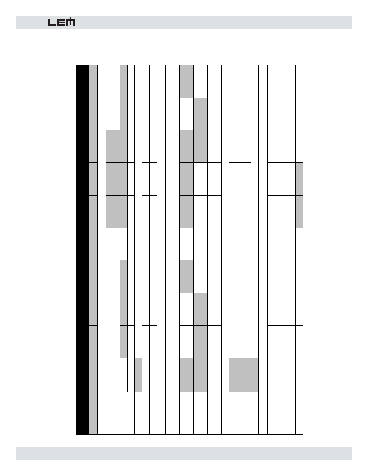
7. Technical Specifi cations
H150A H200A H300A H350A H350SA H400SA H100MA H200MA H300MA
High
1.5"
su
p
er-tweeter
Mid
8" midrange
Low
10" woofer 12" woofer 15" woofer 15" woofer 15" woofer 18" woofer 8" full-range 12" woofer 15" woofer
Construction
Dimensions
mm (WxHxD)
340x460x285 390x508x325 455x580x405 455x790x405 475x555x520 625x540x545 305x395x275 390x508x325 455x580x405
Weight
kg
18,5 22 27,5 33,5 35,6 43 13 20,5 27
Input
sensitivit
y
im
p
edance
Passive
crossover
3.5Khz
12/18dB/ott.
3.5Khz
12/18dB/ott.
6Khz
12/12dB/ott.
3.5Khz
12/18dB/ott.
Active
crossover
3.5Khz
12/18dB/ott.
600Hz
18/18dB/ott.
80-320Hz
12dB/ott.
80-320Hz
12dB/ott.
3.5Khz
12/18dB/ott.
Output power
EIA (1kHz, THD 1%)
W High
W Low
150 200
50
250
80
270
350 400 100 200
50
250
Distortion
%
Controls
Connections
Power supply
Frequency
response
Hz (-10dB) 60-20Khz 55-20Khz 48-20Khz 38-25Khz 38-300 32-300 65-20Khz 55-20Khz 48-20Khz
Sensitivity
MAX SPL
continuous
117dB 120dB 123dB 122dB 121dB 122dB 114dB 120dB 123dB
Dispersion
°
60x40 60x40 60x40 120x40 90x90 60x40 60x40
2 x JACK + XLR-F (in)
2 x JACK + XLR-M (out)
High-density poplar chipboard with scratch-resistant gark grey carpet - Metal grid - 1/2 handles - Speaker stand adapter
LOUDSPEAKER SPECIFICATIONS
1" driver with EWT horn
0 dB (nominal)
20 kOhms (bialanced)
Components
1" driver with EWT horn
HURRICANE ACTIVE SERIES • TECHNICAL SPECIFICATIONS
AMPLIFIER SPECIFICATIONS
SYSTEM SPECIFICATIONS
see label
<0.02
Volume - SHIELD Volume - SHIELD - Xover freq. Volume - SHIELD
1 x XLR-F + 1 x JACK in parallel 1 x XLR-F + 1 x JACK in parallel
Page 9
9
hurricane active
FIG. 1 - THE MODELS
Page 10
10
hurricane active
FIG. 1 - THE MODELS
Page 11
11
hurricane active
FIG. 2 - CONNECTOR CABLES
FIG. 3 - CONNECTOR PANELS
XLR-M balanced XLR-M unbalanced
XLR-F balanced XLR-F unbalanced
JACK balanced JACK unbalanced
Page 12
12
hurricane active
FIG. 4 - SUB-WOOFER + SATELLITE SETUPS
SINGLE
SETUP
DOUBLE
SETUP
Page 13

Le informazioni contenute in questo documento sono state at ten ta men te redatte e controllate. Tuttavia non
è assunta alcuna re spon sa bi li tà per eventuali inesattezze.
Tutti i diritti sono riservati e questo documento non può essere copiato, fotocopiato, riprodotto per intero o
in parte senza previo consenso scritto della GENERALMUSIC S.p.A.
GENERALMUSIC si riserva il diritto di apportare senza preavviso cam bia men ti e modifi che estetiche,
funzionali o di design a ciascun proprio prodotto.
GENERALMUSIC non assume alcuna responsabilità sull’uso o sul l’ap pli ca zio ne dei prodotti o dei circuiti
qui descritti.
STAMPATO IN ITALIA
The information contained in this publication has been carefully prepared and checked. However no
responsibility will be taken for any errors.
All rights are reserved and this document cannot be copied, photocopied or reproduced in part or completely
without written consent being obtained in advance from GENERALMUSIC S.p.A.
GENERALMUSIC reserves the right to make any aesthetic, functional or design modifi cation to any of its
products without any prior notice.
GENERALMUSIC assumes no responsibility for the use or application of the products or circuits described
herein.
PRINTED IN ITALY
Page 14

 Loading...