

Page 1
1
Contents
Warnings and Installation . . . . . . . . . . . . . . . . . . . . . . . . 4
Introduction . . . . . . . . . . . . . . . . . . . . . . . . . . . . . . . . . . . 5
Front Panel. . . . . . . . . . . . . . . . . . . . . . . . . . . . . . . . . . . . 6
Rear Panel . . . . . . . . . . . . . . . . . . . . . . . . . . . . . . . . . . . . 8
Signal Processing . . . . . . . . . . . . . . . . . . . . . . . . . . . . . 10
Getting Started . . . . . . . . . . . . . . . . . . . . . . . . . . . . . . . 11
Before starting . . . . . . . . . . . . . . . . . . . . . . . . . . . . . . . . . . . . . . 11
The Basic Principles of Navigation and Editing . . . . . . . . . . . . . 11
Configuration of the System. . . . . . . . . . . . . . . . . . . . . . . . . . . . 12
Adjusting the input signal . . . . . . . . . . . . . . . . . . . . . . . . . . . . . 13
First Setup . . . . . . . . . . . . . . . . . . . . . . . . . . . . . . . . . . . . . . . . 14
Display information in default conditions . . . . . . . . . . . . . . . . . . 15
System configuration . . . . . . . . . . . . . . . . . . . . . . . . . . . . . . . . . . . . 15
Number of PRESETS. . . . . . . . . . . . . . . . . . . . . . . . . . . . . . . . . . . 16
Type of PRESET . . . . . . . . . . . . . . . . . . . . . . . . . . . . . . . . . . . . . . 16
Name of the PRESET . . . . . . . . . . . . . . . . . . . . . . . . . . . . . . . . . . 16
PRESET Modifications . . . . . . . . . . . . . . . . . . . . . . . . . . . . . . . . . 17
System Protection . . . . . . . . . . . . . . . . . . . . . . . . . . . . . . . . . . . . . . 17
Menu map. . . . . . . . . . . . . . . . . . . . . . . . . . . . . . . . . . . . 18
Menu map . . . . . . . . . . . . . . . . . . . . . . . . . . . . . . . . . . . . . . . . . 18
Variations of the Audio Parameter editing pages . . . . . . . . . . . . 20
PRESET menu . . . . . . . . . . . . . . . . . . . . . . . . . . . . . . . . 22
Load PRESET . . . . . . . . . . . . . . . . . . . . . . . . . . . . . . . . . . . . . . 23
Store & Naming PRESET . . . . . . . . . . . . . . . . . . . . . . . . . . . . . 24
Dump Out PRESET . . . . . . . . . . . . . . . . . . . . . . . . . . . . . . . . . . 25
Incoming Dump . . . . . . . . . . . . . . . . . . . . . . . . . . . . . . . . . . . . . 25
Contents
Page 2

2
DELAY Menu . . . . . . . . . . . . . . . . . . . . . . . . . . . . . . . . . 26
The practical differences between Input and Output Delay . . . . . . . . 26
Input Delay. . . . . . . . . . . . . . . . . . . . . . . . . . . . . . . . . . . . . . . . . 27
Output Delay . . . . . . . . . . . . . . . . . . . . . . . . . . . . . . . . . . . . . . . 28
EDIT menu . . . . . . . . . . . . . . . . . . . . . . . . . . . . . . . . . . . 29
Input Gain . . . . . . . . . . . . . . . . . . . . . . . . . . . . . . . . . . . . . . . . . 29
Input Noise Gate . . . . . . . . . . . . . . . . . . . . . . . . . . . . . . . . . . . . 30
Input EQ. . . . . . . . . . . . . . . . . . . . . . . . . . . . . . . . . . . . . . . . . . . 31
Type of filter . . . . . . . . . . . . . . . . . . . . . . . . . . . . . . . . . . . . . . . . . . 32
Centre Frequency / Cutoff Frequency . . . . . . . . . . . . . . . . . . . . . . . 32
Bandwidth . . . . . . . . . . . . . . . . . . . . . . . . . . . . . . . . . . . . . . . . . . . . 32
Gain . . . . . . . . . . . . . . . . . . . . . . . . . . . . . . . . . . . . . . . . . . . . . . . . . 33
Xover . . . . . . . . . . . . . . . . . . . . . . . . . . . . . . . . . . . . . . . . . . . . . 34
Low Pass Filter . . . . . . . . . . . . . . . . . . . . . . . . . . . . . . . . . . . . . . . . 34
High Pass Filter . . . . . . . . . . . . . . . . . . . . . . . . . . . . . . . . . . . . . . . . 34
Type of filter . . . . . . . . . . . . . . . . . . . . . . . . . . . . . . . . . . . . . . . . . . 35
Crossover frequency . . . . . . . . . . . . . . . . . . . . . . . . . . . . . . . . . . . . 35
Phase . . . . . . . . . . . . . . . . . . . . . . . . . . . . . . . . . . . . . . . . . . . . . . . 35
Output EQ . . . . . . . . . . . . . . . . . . . . . . . . . . . . . . . . . . . . . . . . . 36
Output Gain . . . . . . . . . . . . . . . . . . . . . . . . . . . . . . . . . . . . . . . . 37
Output Pol. . . . . . . . . . . . . . . . . . . . . . . . . . . . . . . . . . . . . . . . . . 37
Output Compressor/Limiter . . . . . . . . . . . . . . . . . . . . . . . . . . . . 38
Reaction times . . . . . . . . . . . . . . . . . . . . . . . . . . . . . . . . . . . . . . . . 38
Threshold . . . . . . . . . . . . . . . . . . . . . . . . . . . . . . . . . . . . . . . . . . . . 38
Ratio . . . . . . . . . . . . . . . . . . . . . . . . . . . . . . . . . . . . . . . . . . . . . . . . 39
UTILITY Menu. . . . . . . . . . . . . . . . . . . . . . . . . . . . . . . . . 40
Ganging submenu . . . . . . . . . . . . . . . . . . . . . . . . . . . . . . . . . . . 41
Input Ganging . . . . . . . . . . . . . . . . . . . . . . . . . . . . . . . . . . . . . . . . . 42
Output Ganging . . . . . . . . . . . . . . . . . . . . . . . . . . . . . . . . . . . . . . . . 42
Units submenu . . . . . . . . . . . . . . . . . . . . . . . . . . . . . . . . . . . . . . 43
Delay Unit . . . . . . . . . . . . . . . . . . . . . . . . . . . . . . . . . . . . . . . . . . . . 43
Lim. Thresh. Unit . . . . . . . . . . . . . . . . . . . . . . . . . . . . . . . . . . . . . . . 43
Temperature Unit . . . . . . . . . . . . . . . . . . . . . . . . . . . . . . . . . . . . . . 43
Misc. Setup submenu . . . . . . . . . . . . . . . . . . . . . . . . . . . . . . . . 44
Contents
Page 3
3
Contents
Input Select . . . . . . . . . . . . . . . . . . . . . . . . . . . . . . . . . . . . . . . . . . . 44
Output Meters . . . . . . . . . . . . . . . . . . . . . . . . . . . . . . . . . . . . . . . . . 45
Temperature . . . . . . . . . . . . . . . . . . . . . . . . . . . . . . . . . . . . . . . . . . 45
Wake Up . . . . . . . . . . . . . . . . . . . . . . . . . . . . . . . . . . . . . . . . . . . . . 46
LCD Contrast . . . . . . . . . . . . . . . . . . . . . . . . . . . . . . . . . . . . . . . . . 46
Lock submenu . . . . . . . . . . . . . . . . . . . . . . . . . . . . . . . . . . . . . . 47
How to enable protection . . . . . . . . . . . . . . . . . . . . . . . . . . . . . . . . . 47
Protection mode . . . . . . . . . . . . . . . . . . . . . . . . . . . . . . . . . . . . . . . 47
Password . . . . . . . . . . . . . . . . . . . . . . . . . . . . . . . . . . . . . . . . . . . . 47
How to disable the protection . . . . . . . . . . . . . . . . . . . . . . . . . . . . . 48
Memory Card submenu . . . . . . . . . . . . . . . . . . . . . . . . . . . . . . . 49
How to format the Card . . . . . . . . . . . . . . . . . . . . . . . . . . . . . . . . . . 49
Comm. Setup submenu . . . . . . . . . . . . . . . . . . . . . . . . . . . . . . . 50
PRESET Change RX . . . . . . . . . . . . . . . . . . . . . . . . . . . . . . . . . . . 50
Configurations . . . . . . . . . . . . . . . . . . . . . . . . . . . . . . . . 51
Connections. . . . . . . . . . . . . . . . . . . . . . . . . . . . . . . . . . 54
Factory PRESETS . . . . . . . . . . . . . . . . . . . . . . . . . . . . . 61
Technical Specifications . . . . . . . . . . . . . . . . . . . . . . . . 62
Page 4
4
Warnings and Installation
✔ ✔
✔ ✔
✔
Connection to the mains supply
The unit has its own built-in power supply. Before switching on the unit, make certain that the mains voltage
matches that shown on the rear (a tolerance of up to ±10% is acceptable). Before connecting or disconnecting
the power cord, make certain the ON/OFF switch is in the OFF position.
✔ ✔
✔ ✔
✔
Switching on and off
CAUTION: before switching on or off, make certain that the sound system’s amplifiers are off or that all unit’s
outputs are automatically forced into MUTE status: this will avoid signal peaks, which are annoying and
sometimes dangerous (particularly for speaker enclosures).
✔ ✔
✔ ✔
✔
Connecting and preventing or identifying interference
First of all, check that the apparatus is installed in a place free from industrial or RF (radio frequency) interference. Avoid installing your equipment very near radio or TV sets, mobile phones, etc., as these can cause
noisy interference. When connecting the other parts of your sound system, watch out for the so-called “ground
loops”, which could cause hum and jeopardize the products’s excellent Sound-to-Noise and low distortion
characteristics.
The best way (even if not always feasible) to avoid ground loops is to connect the electric ground of all the
equipment to a single central point (“star” system). In this case, the central point can be the mixer.
✔ ✔
✔ ✔
✔
Protection and maintenance
Don’t force knobs or switches: these are designed and manufactured to respond to light pressure and could
be damaged if used with excessive force. Take care of your connector cables, a very frequent cause of small/
big problems. Always grip them by the connector, avoid pulling them forcefully and wind them without forming
knots or sharp bends: they’ll last longer this way, and be more reliable, which is a definite advantage.
Avoid exposing the product to strong direct sunlight, high temperatures or intense vibrations, in very dusty or
particularly damp surroundings or, even worse, in the rain: this will help to avoid the risk of faulty operation,
deterioration or even electric shocks and fires. The product is built in shock-resistant material. Nevertheless,
protect it during transport with a flight-case to avoid the risk of any casual accidents. When you’ve finished
using the apparatus, it’s always advisable to protect it from dust, but any dust that does form should be
removed using a cloth or a soft brush. Never use alcohol, acetone or any solvents. The effect does not require
any other maintenance.
✔ ✔
✔ ✔
✔
In the event of breakdown
All user-adjustable parts are external and easily accessed. In the event of a breakdown, do not open the
apparatus, but contact the nearest Generalmusic/Lem Service Centre.
✔ ✔
✔ ✔
✔
Keeping the documentation
Keep this user’s manual for future consultation. Also remember that the effect will get a better price on the
secondhand market if (as well as being in good condition) it has its original documentation and packaging.
Warnings and Installation
Page 5
5
Introduction
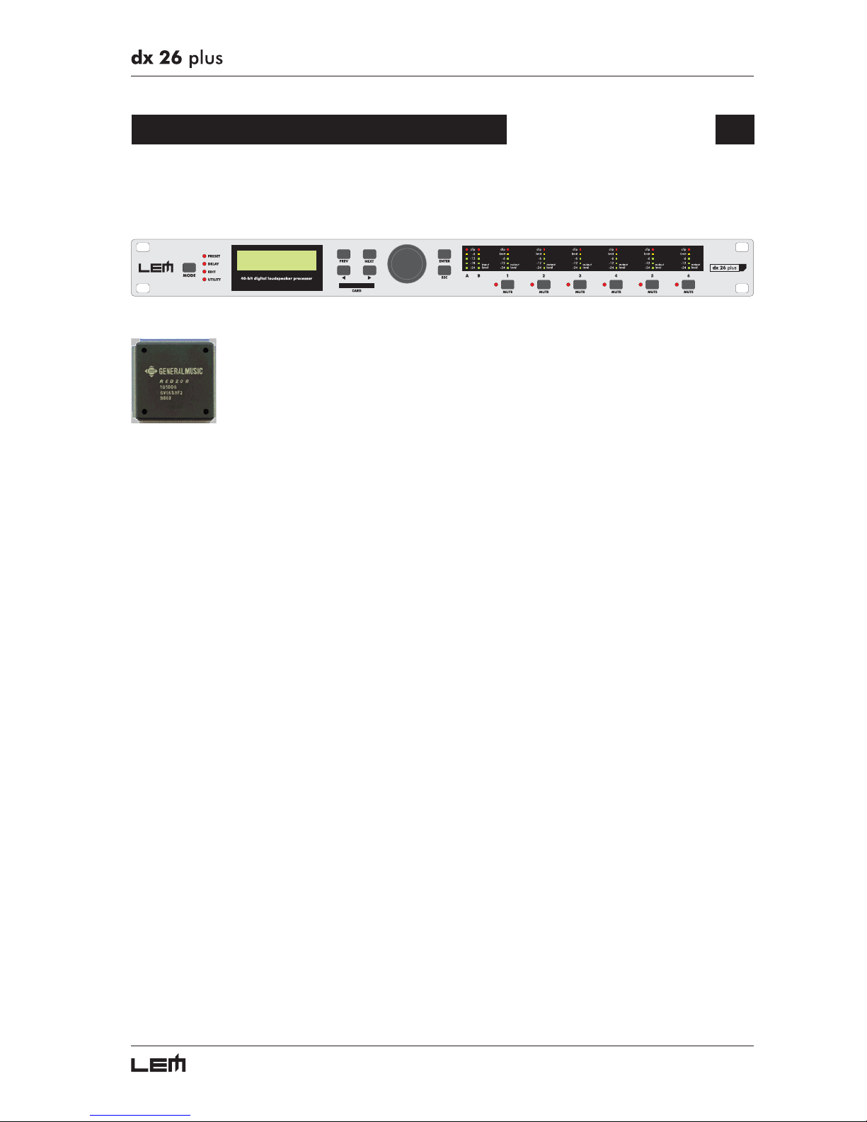
Congratulations for having chosen the DX 26 PLUS!
DX 26 PLUS is an extremely versatile digital processor for loudspeaker systems
based on the GENERALMUSIC custom DSP RED 208. This powerful 40 bit resolution
DSP, together with low-noise 24 bit converters, provides an extremely high processing
quality and a dynamics suitable for the most professional applications.
DX 26 PLUS has 2 inputs (analog or digital) and 6 independent outputs and
can be configured as 2 or 3-way stereo, 2, 3, 4, 5 and 6-way mono or as distribution mixer with up
to 6 outputs. Configurations that allows the 2 input signals to be summed and routed to different outputs
are also available
Each of the 2 inputs has:
- MASTER DELAY, available also on the input SUM;
- digital NOISE GATE;
- 5-BAND PARAMETRIC EQ;
- level control.
Each of the 6 outputs has:
- DELAY line;
- 5-BAND PARAMETRIC EQ;
- CROSSOVER HP and LP filters which can be selected from the BESSEL, BUTTERWORTH and
LINKWITZ-RILEY types with slopes up to 48dB;
- phase control with 5° steps through a full 360°;
- digital COMPRESSOR/LIMITER;
- level and MUTE control.
All settings can be stored and recalled in an instant. In fact, the system has:
- 21 Factory PRESETS, each of which can be used as a basic configuration for preparing custom
PRESETS, others already optimized for LEM loudspeaker systems.
- 64 User PRESETS, which can be freely programmed to store all the system settings.
- 128 Card PRESETS, in fact User PRESETS that can be stored on Multimedia Memory Cards.
Each User or Card PRESET can contain any of the Input/Output configurations available.
All operations are carried out via user interface that includes a 2x16 LCD, a convenient DIAL for
the parameter modification and selector buttons for the direct access to all the features. DX 26 PLUS is
also equipped with 2 types of serial interface (RS232 and RS485) for the remote control thru a PC and
for the linking of more units.
Introduction
Page 6
6
Front Panel
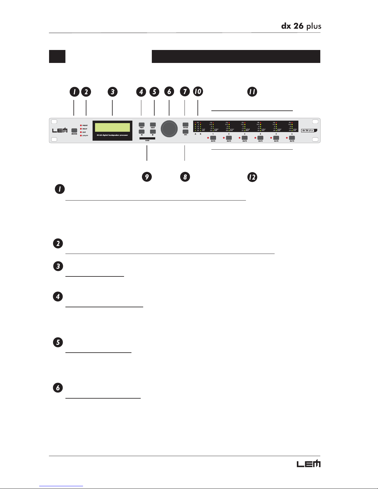
MODE
Key for selecting the PRESET, DELAY, EDIT and UTILITY menus.
Selection is made by pressing MODE repeatedly until the required menu is reached, indicated by
the relative LED. Selecting a menu allows access to the editing of its parameters. If none of the
menu LEDs are lit, the display shows the name of the current PRESET (i.e. the PRESET currently
loaded in the memory) and no parameter can be modified.
LEDs MENU
Show the selection status of the PRESET, DELAY, EDIT and UTILITY menu.
DISPLAY
Rear-lit 2x16 display.
Allows to view the pages of the various menus and the relative parameters.
PREV / NEXT
Menu page navigation keys.
Each menu is made up of several pages, which can in turn contain other pages or a variable number
of parameters. The PREV and NEXT keys allow to go to the previous page or the next one
respectively.
Navigation cursor keys.
Each editing page contains a variable number of parameters (fields).
The
and
keys allow to move the cursor in the page, selecting the various parameters available
as required.
DIAL
Encoder for editing values.
Allows to modify the value of the selected parameter.
Turn the DIAL clockwise to raise the value and counter clockwise to lower it.
Front Panel
Page 7
7
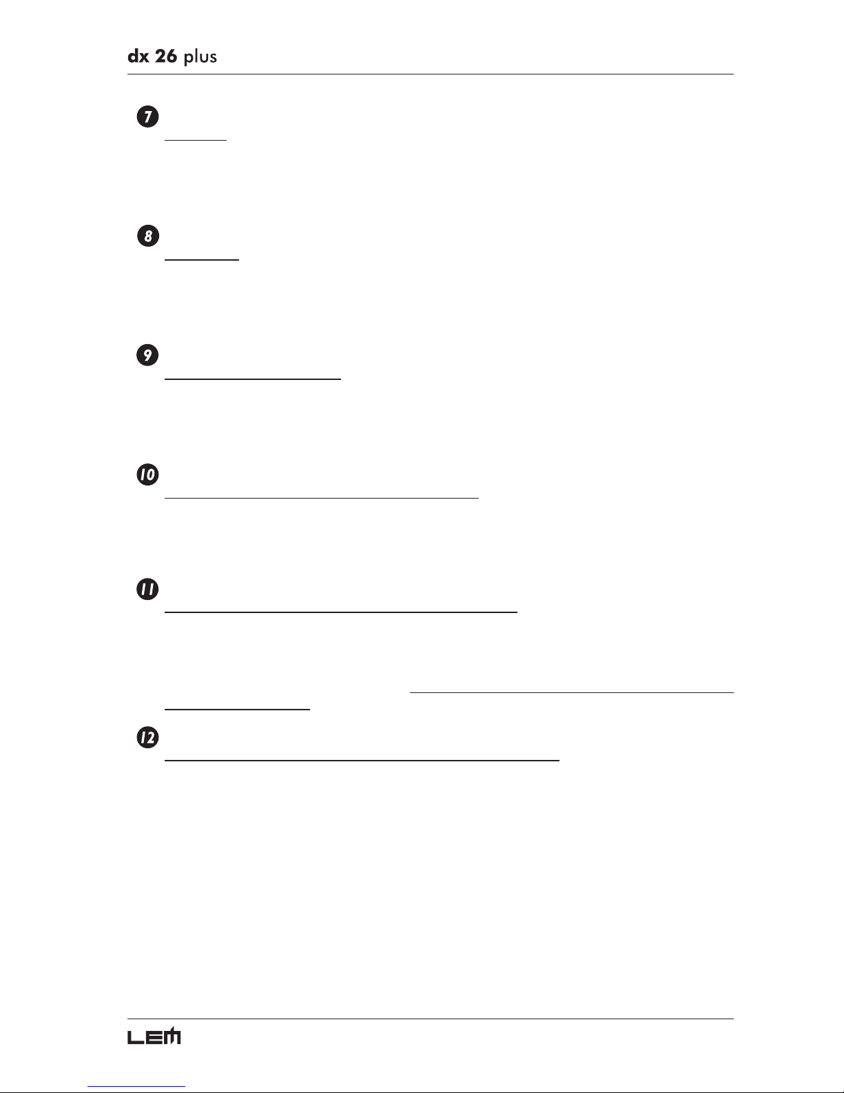
ENTER
Enter key.
☞ Allows access to the editing page whose name is shown on the display.
In some cases (e.g. PRESET name) also allows to:
☞ Access the editing of the selected parameter
☞ Confirm the value entered
ESC
Escape key.
☞ Allows to exit the editing page shown on the display, confirming the value entered.
In some cases (e.g. PRESET name) also allows to:
☞ Exit the editing of the selected parameter
☞ Reject the value entered and return to the stored value.
CARD
Slot for the MEMORY CARD.
Holds a MULTIMEDIA CARD on which 128 User PRESETS can be stored and recalled whenever
required.
MEMORY CARDS are very useful for safe storage for later use of PRESETS and for their transfer
from one DX 26 PLUS to another one.
INPUT LEVEL A-B
LED ladders indicating the level of inputs A and B.
N.B.: the input gain is adjusted using the INPUT GAIN parameter (EDIT menu).
To ensure a good signal/noise ratio, i.e. an up-front distortion-free signal, keep the signal quite
high, but make certain the red CLIP LED doesn’t light up continually. CLIP.
OUTPUT LEVEL 1-2-3-4-5-6
LED ladders showing the level of the respective outputs.
N.B.: the output level is adjusted using the OUTPUT GAIN parameter (EDIT menu).
IMPORTANT! Enabling the LIMITER on any output also changes the way in which the level is
displayed on the corresponding LED ladder: in this case, in fact, the level shown on the ladder is
no longer the “absolute” output level, but the level of the signal at -24dB, -12dB, -6dB compared
to the LIMITER threshold (orange LIMIT LED), whatever the threshold value is.
MUTE 1-2-3-4-5-6
Keys with LEDs for muting the signal of the respective outputs.
When the LED is lit, the MUTE function is enabled and no signal is fed to the relative output.
N.B.: this function is useful for avoiding signal peaks (bumps) when the sound system is switched on and off, for
isolating the individual audio sections during testing or sound checks, to enable or disable sound reinforcement zones
quickly, etc.
The mode in which the MUTE function is restored when the unit is switched on can be set using
the Wake Up function (UTILITY menu, Misc. Setup submenu) and can be set as Normal (last
setting before the unit was switched off) or Mute (all outputs automatically forced into Mute status).
Front panel
Page 8
8
Rear Panel
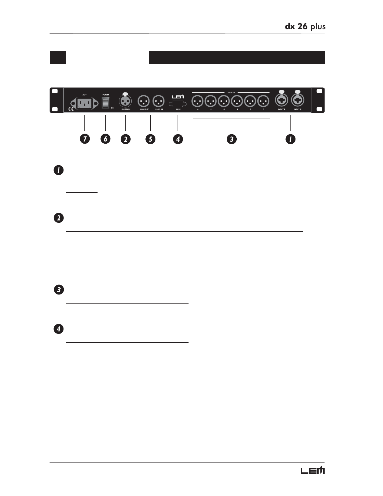
INPUTS A-B
Audio inputs of the respective sections. Combo Connectors (compatible with balanced XLR
and JACK).
The A/D conversion is made with high quality, low noise 20 bit converters.
DIGITAL IN
Digital audio input A-B. Balanced XLR-F connector (one cable is enough to feed both inputs).
The digital inputs can be used in alternative to the analog ones (A & B inputs) to connect the processor
to units fitted with AES/EBU digital outputs (i.e. digital mixers). In this case, two conversions are bypassed, improving the signal quality. The Digital/Analog Input selection can be set using the Input Select function
(UTILITY menu - Misc. Setup submenu).
A signal connected to the digital input has the same processing as that connected to analog input.
OUTPUTS 1-2-3-4-5-6
Audio outputs. Balanced XLR-M connectors.
The D/A conversion is made with high quality, low noise 20 bit converters.
RS232
RS232 serial communication interface port.
Allows incoming and outgoing communication between a DX 26 PLUS and a PC or other DX 26
PLUS units.
Communication protocol includes:
- Remote control: connecting the DX 26 PLUS to a PC and using the LEM editing software is
possible to remotely control all the processor functions.
- PRESET DUMP: connecting two DX 26 PLUS it’s possible to DUMP the single PRESETS from
one unit to the other (see DUMP procedure).
- PROGRAM CHANGE commands send/receive: connecting two DX 26 PLUS it’s possible, when
a PRESET is recalled on the first one, to send a PROGRAM CHANGE command to the second
one to recall the same PRESET number (see LOAD PRESET procedure).
Rear Panel
Page 9
9
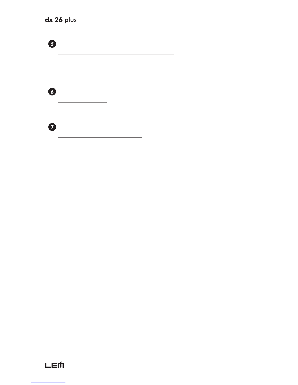
RS485 IN & OUT
RS485 standard serial communication interface port.
Allows incoming and outgoing communication between a DX 26 PLUS and a PC or other DX 26
PLUS units.
The characteristics of the RS485 interface make these ports particularly suitable for remote control
over long distances (difficult with RS232 standard ports) and for daisy-chaining several DX 26 PLUS.
POWER
Unit’s ON/OFF switch.
Before switching on or off, make certain that the sound system’s amplifiers are off to avoid signal
peaks, which are annoying and sometimes dangerous.
AC ~
Connector for the power supply cable.
Before switching on the unit, make certain that the mains voltage matches that shown on the rear
(a tolerance of up to ±10% is acceptable). Before connecting or disconnecting the power cord,
make certain the ON/OFF switch is in the OFF position.
Rear Panel
Page 10
10
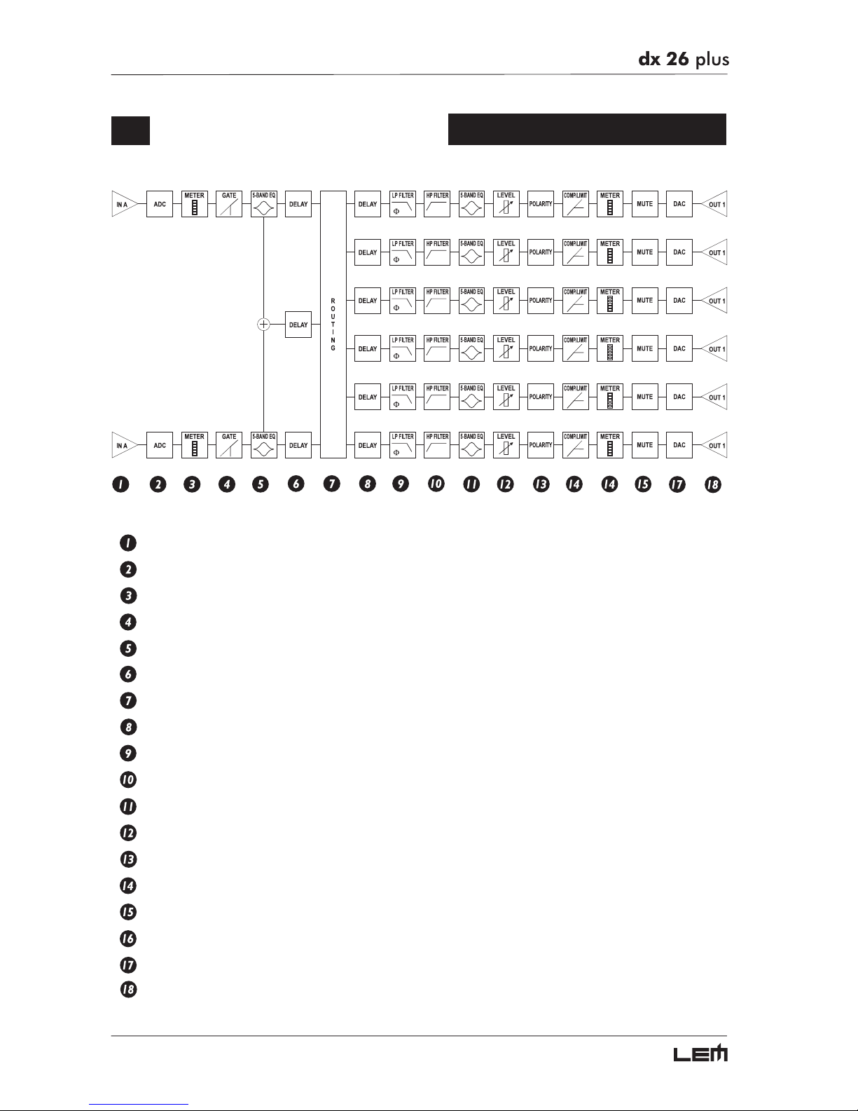
Signal Processing
Balanced inputs (IN A & IN B).
20-bit A/D converters.
LED ladders for monitoring input signals.
NOISE GATE on the inputs.
5-band parametric equalizers for A & B inputs.
3 delay lines (IN A, IN B & Sum A+B).
Routing System for connecting INPUTS and OUTPUTS.
Delay lines in 1-6 output.
Low-pass filters (LPF) with phase fine control - CROSSOVER.
High-pass filters (HPF) - CROSSOVER.
5-band parametric equalizers for the outputs.
Output level controls.
Polarity inverter.
Output level COMPRESSOR/LIMITERS.
LED ladders showing output levels and limiter action.
Output MUTING controls.
20-bit D/A converters.
XLR-M balanced outputs.
Signal Processing
Page 11
11
Getting Started
Before starting
Attention!
Before starting work, remember that the DX 26 PLUS is a powerful versatile signal processor mainly
designed for use with audio systems, whose input and output routing configurations can be set only by
recalling one of the PRESETS included in the internal memory. These characteristics mean that correct
careful use must be made of the unit and users must be sufficiently familiar with the unit’s main functions.
So before going ahead, it’s advisable to get to know at least the introductory part of this manual.
The Basic Principles of Navigation and Editing
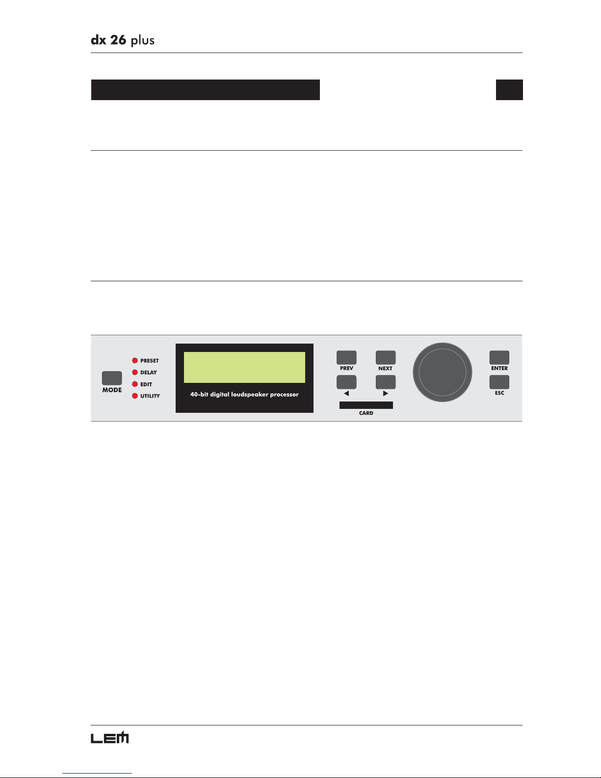
All the DX 26 PLUS parameters and functions can be accessed and edited using the buttons on the
front panel. All available information is shown on each occasion on the display.
The control software is organized in the PRESET, DELAY, EDIT and UTILITY menus, each of which
contains the relative types of parameters and functions. The navigation, i.e. access to the system’s menus,
and changes of the various parameters follow logical criteria, which can be summed up as follows:
☞ The menu is selected using the MODE key.
☞The menu selected is indicated by the relative menu LED and showed on the display.
☞ In default conditions (i.e. when none of the menu LEDs are lit), the display shows the principle infor-
mation on the PRESET currently loaded in the memory.
☞ Each menu is made up of several pages, which can be reached using the PREV and NEXT keys.
☞ Each page is accessed by means of the ENTER key and left using the ESC key or MODE key.
☞ A page can contain other pages. In this case, the name of the page is preceded by an arrow ➔
☞ Each page contains one or more parameters (fields), which can be selected using the
WW
WW
W and
XX
XX
X
keys.
The selected parameter can be identified by its flashing characters.
☞ Changes are made to the selected parameter by means of the DIAL knob.
Changes have immediate effect and, apart from a few exceptions (for example when assigning a
name to a PRESET), don’t need to be confirmed to be entered.
Getting Started
Page 12
12
Configuration of the System
☞ Refer to the Configurations chapter to find the DX 26 PLUS configuration which corresponds with
your sound system (2 x 3 ways; 2 x 2 ways + 2 Aux Mono; etc.)
☞ Refer to the Connections chapter and, with the equipment switched off, carry out the audio and power
connections among the various components of your sound system.
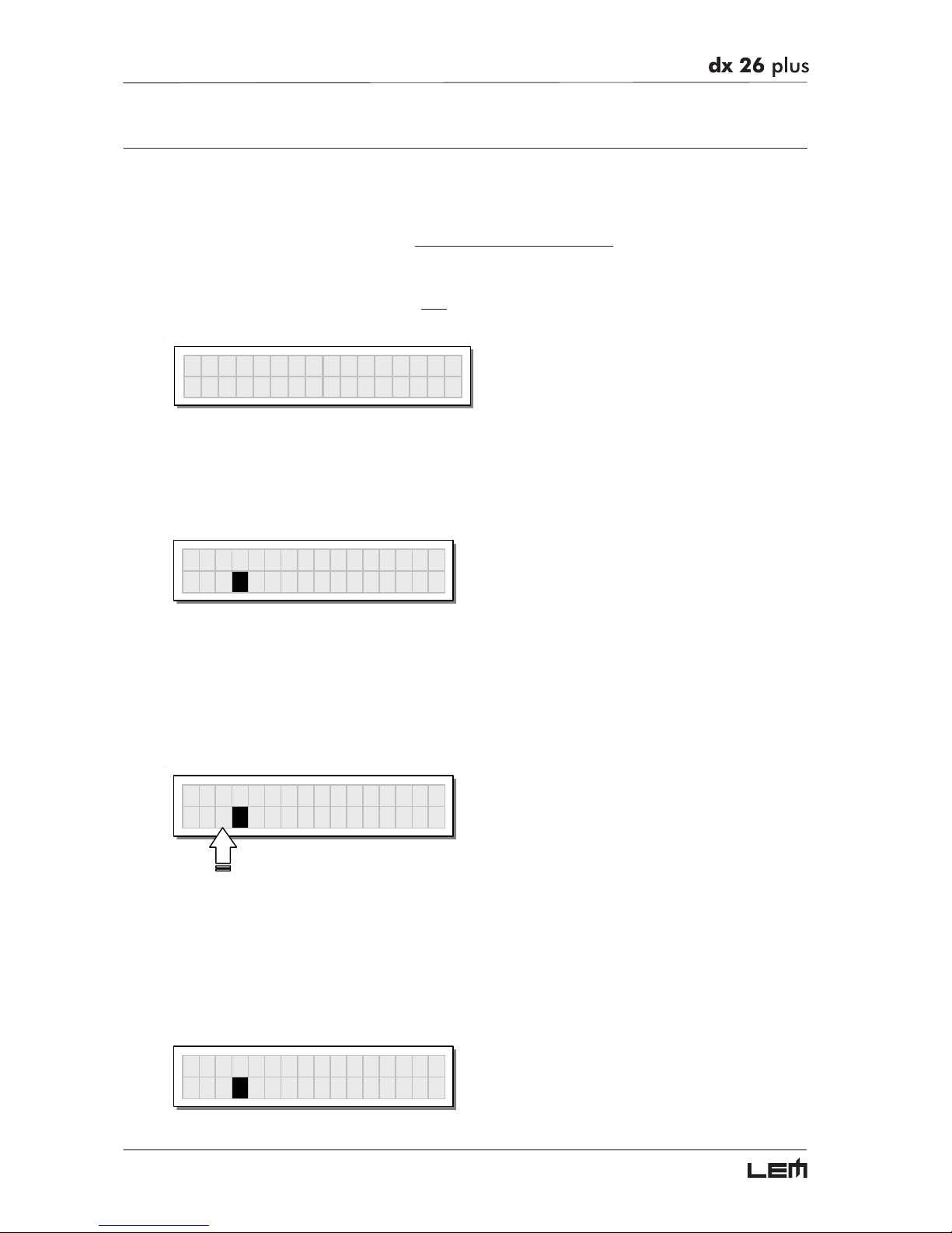
☞ Connect the mains cable and switch on only the DX 26 PLUS. The display shows data regarding the
operating system release for a few seconds.
LEM DX26PLUS
- Release 1.0 -
At the same time, the system restores the exact operating conditions at the time of switching off.
N.B.: in actual fact, a “photograph” of the last scene used is uploaded. This includes the last PRESET loaded, all the
temporary changes (if any) made to it and the settings of the various options of the system.
The system then enters default status, showing the main operating information on the display.
A
13 B24 S56
2U 2x2
W
+2MAX
☞ Set all the DX 26 PLUS outputs in MUTE status (LEDs lit) by pressing the relative keys.
☞ Load the Factory PRESET containing the configuration you’ve found:
Press the MODE Key until the PRESET menu LED lights up.
The display shows the Load PRESET page:
Load Preset
3F 2x3
W
(example)
Use the DIAL to find the necessary Factory PRESET (indicated by the letter F). Check that if, among
the PRESETS available, there are already some optimised for the specific speaker enclosures being
used.
Press ENTER.
The display shows the PRESET loaded in the unit’s memory and the relative configuration:
A
135 B246
3F 2x3
W
(example)
Getting Started
Page 13
13
Adjusting the input signal
Setting the input signal of a digital unit is particularly important, much more than with an analog unit, as
any saturation of the A/D converters caused by excessively high input signals cause a typical particu-
larly distinct noise (high level square wave).
Proceed as follows:
+ Keep the DX 26 PLUS outputs in MUTE status (LEDs lit).
+ Feed a signal in on the DX 26’s input and watch the INPUT LEVEL A-B LED ladders.
To obtain a good signal/noise ratio, i.e. an up-front distortion-free signal, keep the signal quite high, but
make certain the red CLIP LED doesn’t light up continually.
+ First of all, find the output level setting for your mixer (or other unit) connected to the input of the DX 26
PLUS
+ Then adjust the DX 26 PLUS input gain if necessary:
Press the MODE key until the EDIT menu LED lights up.
Use the PREV and NEXT keys to go to the Input Gain page:
´
Input Gain
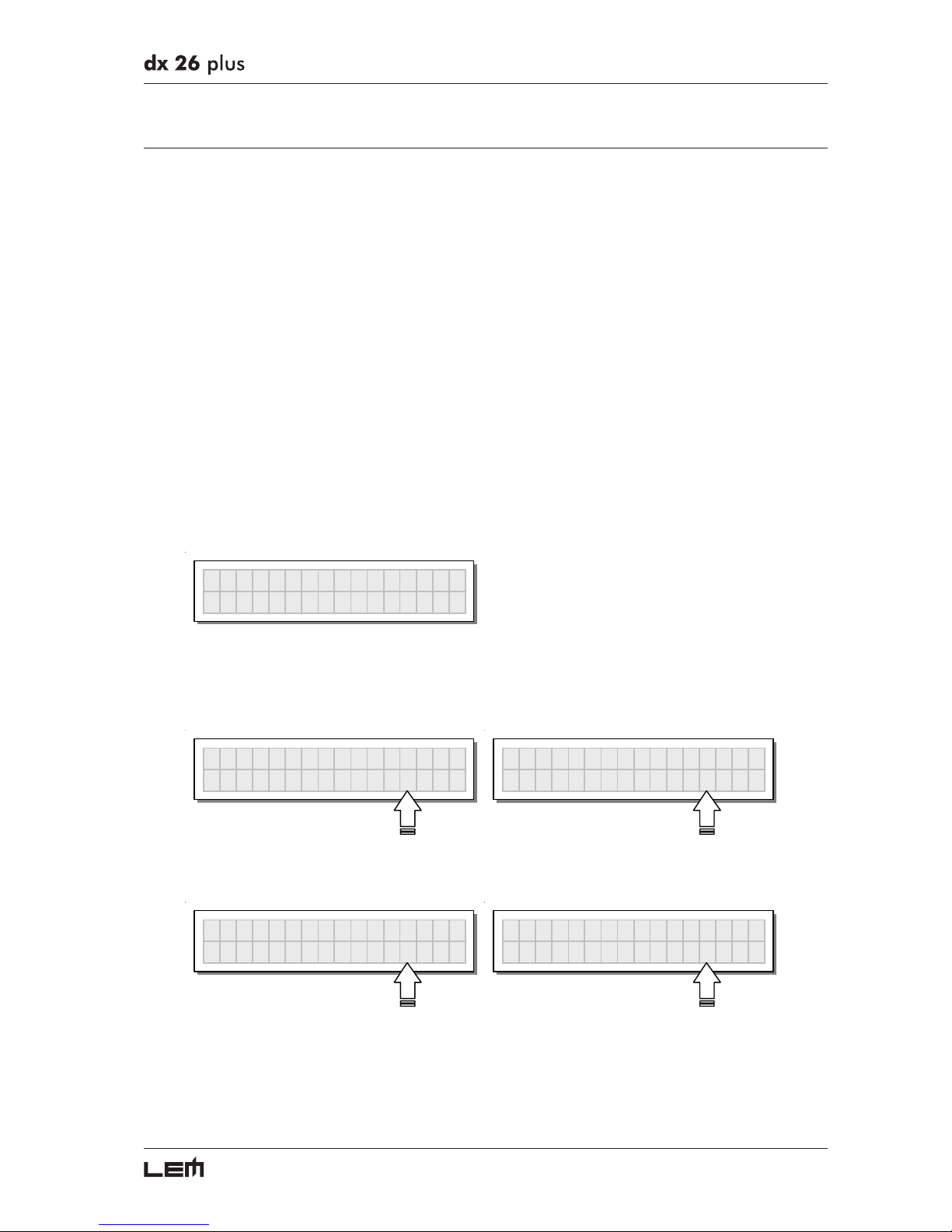
Press ENTER. The display shows the INA Gain or INA&B Gain page (according to the configuration
and other utilities loaded in the memory):
IN
AGA
IN
0.0dB
IN
A
&
BGAIN
0.0dB
Use the DIAL to change the gain value and watch the level of the signal on the LED ladders until the
ideal values are reached.
IN
AGA
IN
-2.5dB
IN
A
&
BGAIN
+6.0dB
Then use the PREV and NEXT keys to access the INB Gain page (if there is one – this depends on the
configuration and the other utilities loaded in the memory).
Repeat the settings as explained above.
Getting Started
Page 14
14
First Setup
At this point, the first custom setup can be prepared.
The following is only a description of setup procedure.
The detailed specifications of each parameter are shown in the respective paragraphs of the manual.
☞ Firstly, set the following parameters in the order shown:
Output Pol. Polarity of the outputs
Xover Crossover frequencies (separation of the speaker channels)
Output Delay Alignment of the speaker enclosure components
Output Gain Levels of the outputs
N.B.: the regulation of the DX 26’s parameters is closely linked to the characteristics of the sound system’s components.
So if you’re not experts, refer to the documentation and technical specifications of your power amplifiers, loudspeaker
enclosures, monitors, etc. This will enable you to work faster and safely.
☞ Disable the MUTE function on the outputs you intend using and listen the sound, carry out instrumental
checks (if you have the necessary equipment) and any corrections required.
☞ Then, if necessary, adjust the values of the following functions:
Output EQ Output equalizers
Output Comp/Limit Output compressor/limiters
N.B.: in this first phase of setting up your sound system, the adjustment of these functions (which are very useful, if
not indispensable during installation) can wait. Remember however that adjusting the equalizers also affects the signal
level. So if considerable equalization changes are made, remember to check and if necessary adjust the output levels
too.
Getting Started
Page 15
15
Display information in default conditions
In default conditions, i.e. when none of the menu LED’s is lit, so no type of editing is enabled, the
display shows the main information on the PRESET currently stored in the memory:
A
13 B24 S56
2U 2x2
W
+2MAX
There are various information areas:
System configuration
A
13 B24 S56
2U 2x2
W
+2MAX
System configuration
The bold letters indicate the inputs:
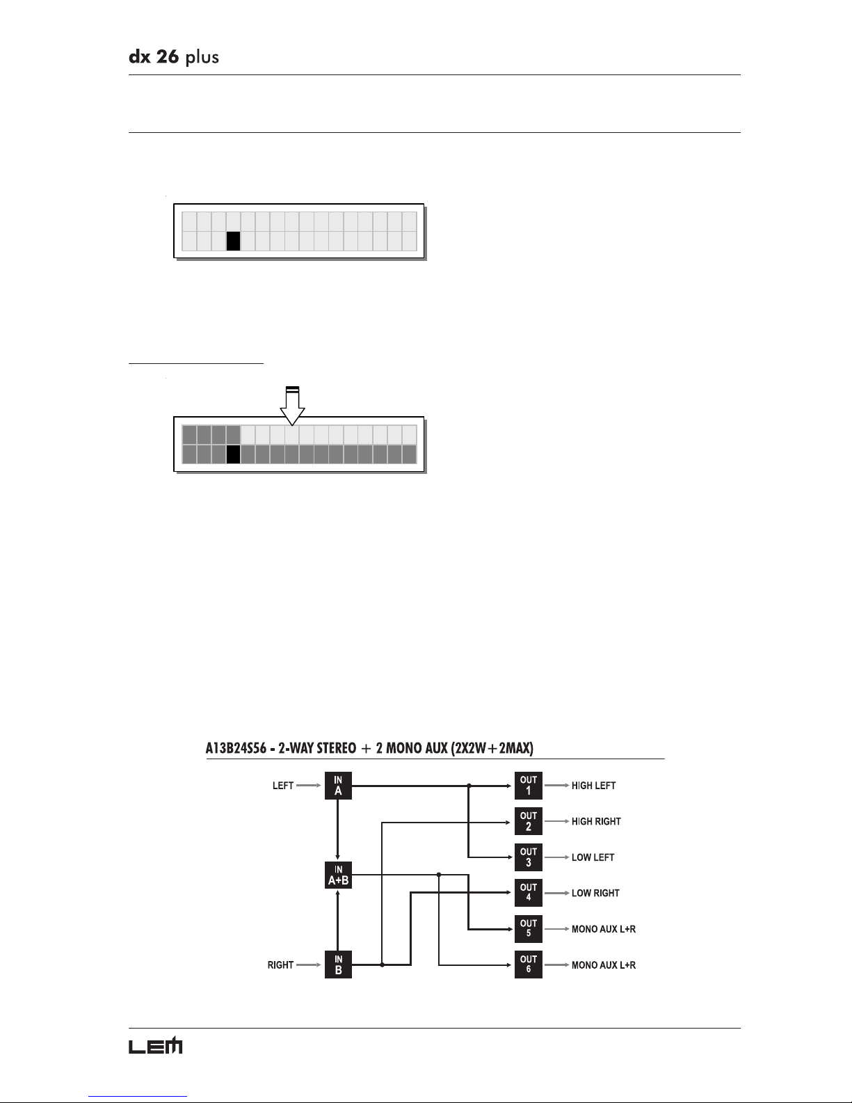
A = Input A
B = Input B
S = SUM (sum of inputs A and B)
Numbers 1, 2, 3, 4, 5 and 6 indicate the respective outputs.
In the example:
The signal connected to Input A is assigned to outputs 1 and 3.
The signal connected to Input B is assigned to outputs 2 and 4.
The Sum of the signal on inputs A and B is assigned to outputs 5 and 6.
The system is therefore configured as shown in the following diagram.
Getting Started
Page 16
16
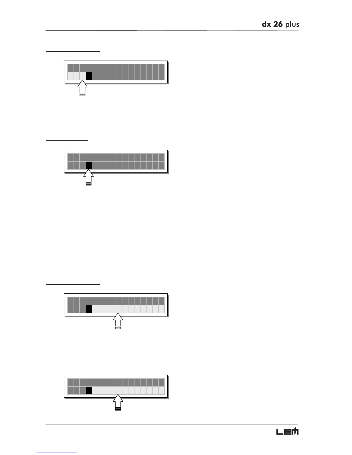
Number of PRESETS
A
13 B24 S56
2U 2x2
W
+2MAX
Number of PRESET
21 Factory PRESETS, 128 User PRESETS and 128 Card PRESETS are available.
Type of PRESET
A
13 B24 S56
2U 2x2
W
+2MAX
Type of PRESET
There are 3 categories of PRESETS:
F = Factory PRESETS factory programmed, cannot be permanently changed.
These include all the system’s usable configurations + some specific setups
for LEM enclosures.
These are the starting points for creating User PRESETS and Card PRESETS
from scratch.
U = User PRESETS can be programmed by users.
C = Card PRESETS can be programmed by users and stored on a Multimedia Memory Card.
Name of the PRESET
A
13 B24 S56
2U 2x2
W
+2MAX
Name of the PRESET
In the example, the name indicates a two-way stereo system + two auxiliary mono outputs.
N.B.: the name of a Factory PRESET normally indicates the general structure of the sound system to be connected
to the DX 26 PLUS or of a specific speaker enclosure model.
The name of a User PRESET and a Card PRESET can be edited as required. For example:
A
13 B24 S56
2U M
y
LiveSetu
p
Getting Started
Page 17
17
PRESET Modifications
M
A
13 B24 S56
2U 2x2
W
+2MAX
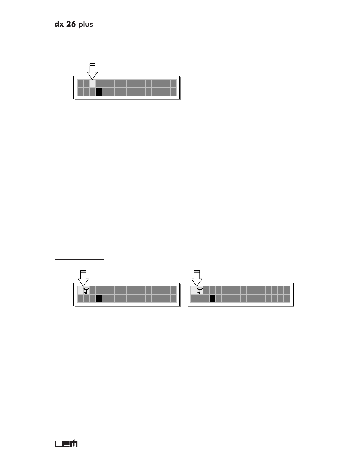
PRESET Modifications
This indication shows that the value of one or more parameters has been temporarily modified with
respect to the values stored in the PRESET shown.
Practically speaking, this indication means that the changes made to the PRESET have not been
stored.
N.B.: once it has been enabled, the indication remains even if the “original” values are reset manually.
The indication disappears as soon as the PRESET is saved or as soon as a new PRESET is loaded
(including this same PRESET).
In other words, the indication disappears as soon as stored values are accessed.
If the PRESET isn’t saved, temporary changes are lost as soon as a new PRESET is loaded (including
this same PRESET).
N.B.: temporary changes are kept on the other hand in the “buffer memory”: when the unit is switched on, the system
maintains exactly the same settings as when the unit was switched off, including temporary changes.
System Protection
T
A
13 B24 S56
2U 2x2
W
+2MAX
P
A
13 B24 S56
2U 2x2
W
+2MAX
These indications appear when the LOCK function (UTILITY menu) is enabled, i.e. when the system is
totally (T) or partially (P) protected against accidental or unauthorized changes (even if temporary).
Protection is ensured by a password, without which editing procedure can’t be unlocked.
Getting Started
Page 18
18
Menu map
Menu map
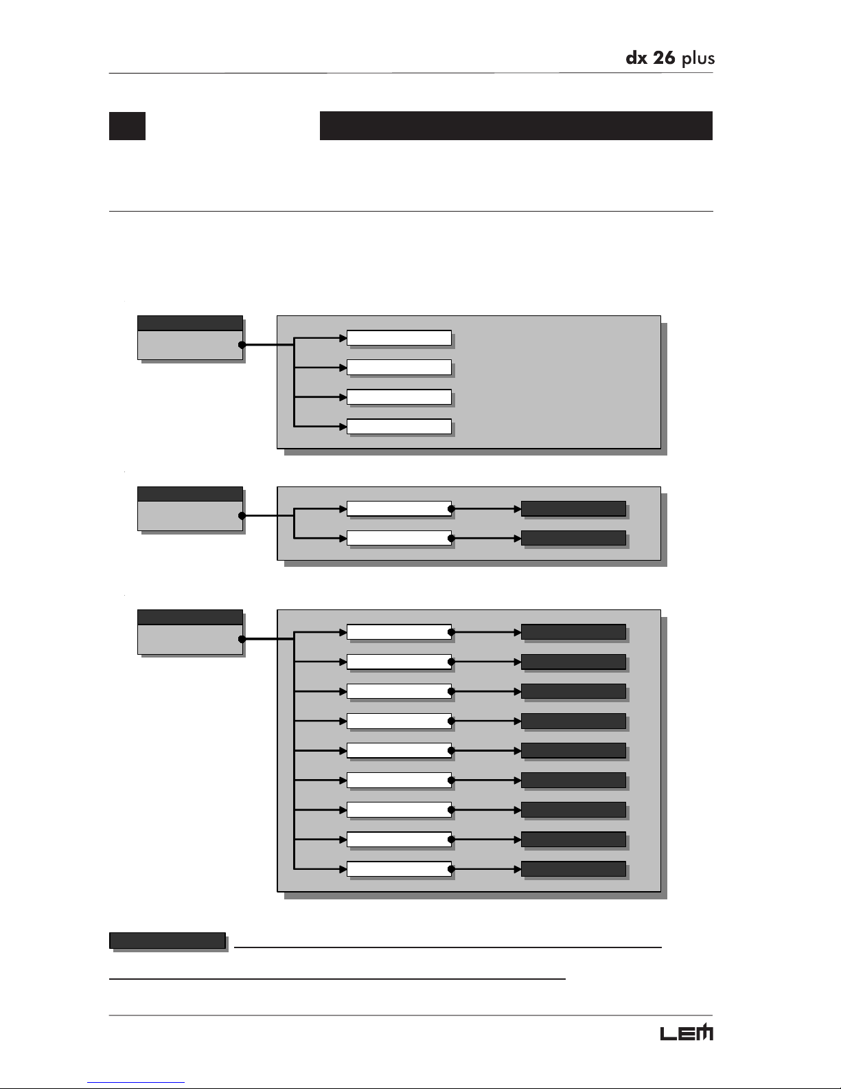
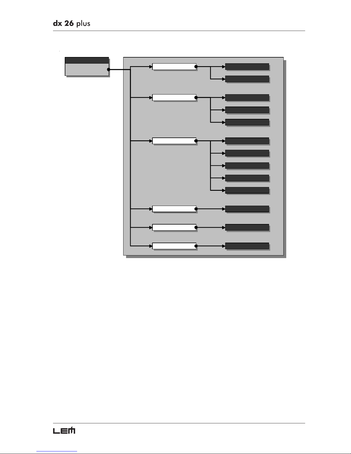
The control software is organized in PRESET, DELAY, EDIT and UTILITY menus, each of which contains
the relative types of parameters and functions.
To facilitate menu navigation, refer to the following map:
menu
PRESET
Load Preset
Store Preset
Dump Out Pre set
Incoming Dump
menu
DELAY
Input Delay
Output Delay
para mete rs
para mete rs
menu
EDIT
Input Gain
Input EQ
Noise Gate
Xover
Output EQ
Output Gain
Output Pol .
para mete rs
para mete rs
para mete rs
para mete rs
para mete rs
para mete rs
para mete rs
Output Cmp/Limit para mete rs
Input GATE para mete rs
parameters
In these pages, the number of the parameters and how they are presented varies according
to the configuration of the PRESET and according to Ganging and Units settings (UTILITY menu). In fact, these pages
only show the parameters that can actually be used, in the most suitable form of editing.
Menu map
Page 19
19
menu
UTILITY
Comm. Setup Preset Change RX
Ganging Input Ganging
Output Ganging
Delay UnitUnits
Lim. Thresh. Unit
Temperature Unit
Input SelectMisc. Setup
Output Me ters
Temperature
Wake Up
LCD Contra st
Lock Lock
Memory Card Forma t Card
Menu map
Page 20
20
Variations of the Audio Parameter editing pages
parameters
DX 26 PLUS can be configured with a large number of IN/OUT combinations.
In some configurations certain parameters aren’t used.
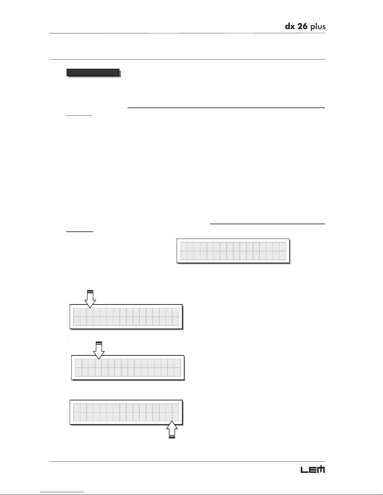
To streamline editing,
the system only presents the parameters that can be used on each
occasion.
For example, in the case of a 6-way configuration, input B and SUM aren’t used. The system
therefore only presents the parameters relative to Input A.
Some functions also affect the way in which parameters are edited or represented.
The Ganging function (UTILITY menu) allows to “group together” the treatment of compatible inputs
and/or outputs.
For example, it allows to equalize simultaneously and with identical values the two outputs which
feed the mid sections of a stereo sound system.
The Units option (UTILITY menu) allows to edit the values of several functions using the
measurement units preferred.
For example, it allows to edit the Delay in meters, millimeters, milliseconds or microseconds.
In these cases too, the system automatically presents the parameters in the most suitable type
of editing.
For example, in the Input Delay function
´
Input Dela
y
according to the configuration of the PRESET and according to Ganging and Units settings, the
system can have variations of this type:
IN
A
DELAY
77ms
Editing of individual inputs
IN
A
&
B DELAY
77ms
Editing of ganged inputs
IN
A
DELAY
26.5m
Measurement units preferred
Menu map
Page 21
21
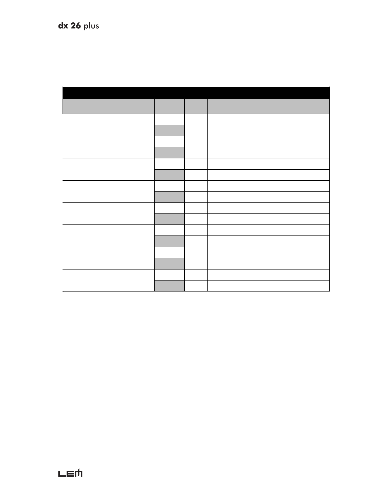
This also affects the number and contents of the editing pages on each occasion.
For example, the INPUT DELAY editing pages can have the following variations:
INPUT
GANGING
PAGES
OFF 3 INA Delay INB Delay SUM Delay
ON 2INA&B Delay SUM Delay
OFF 2 INA Delay INB Delay
ON 1INA&B Delay
OFF 2 INA Delay SUM Delay
ON 2INA Delay SUM Delay
OFF 3 INA Delay INB Delay SUM Delay
ON 3INA Delay INB Delay SUM Delay
OFF 2 INA Delay SUM Delay
ON 2INA Delay SUM Delay
OFF 3 INA Delay INB Delay SUM Delay
ON 3INA Delay INB Delay SUM Delay
OFF 1 INA Delay
ON 1INA Delay
OFF 2 INA Delay INB Delay
ON 2INA Delay INB Delay
PARAMETERSCONFI GURATION
DX 26 PLUS - INPUT DELAY EDITING PAGES
A13 B24 S56
A135 B246
A1234 S56
A123 B4 S56
A12345 S6
A12345 B6
A1234 B5 S6
A123456
Menu map
Page 22
22
PRESET menu
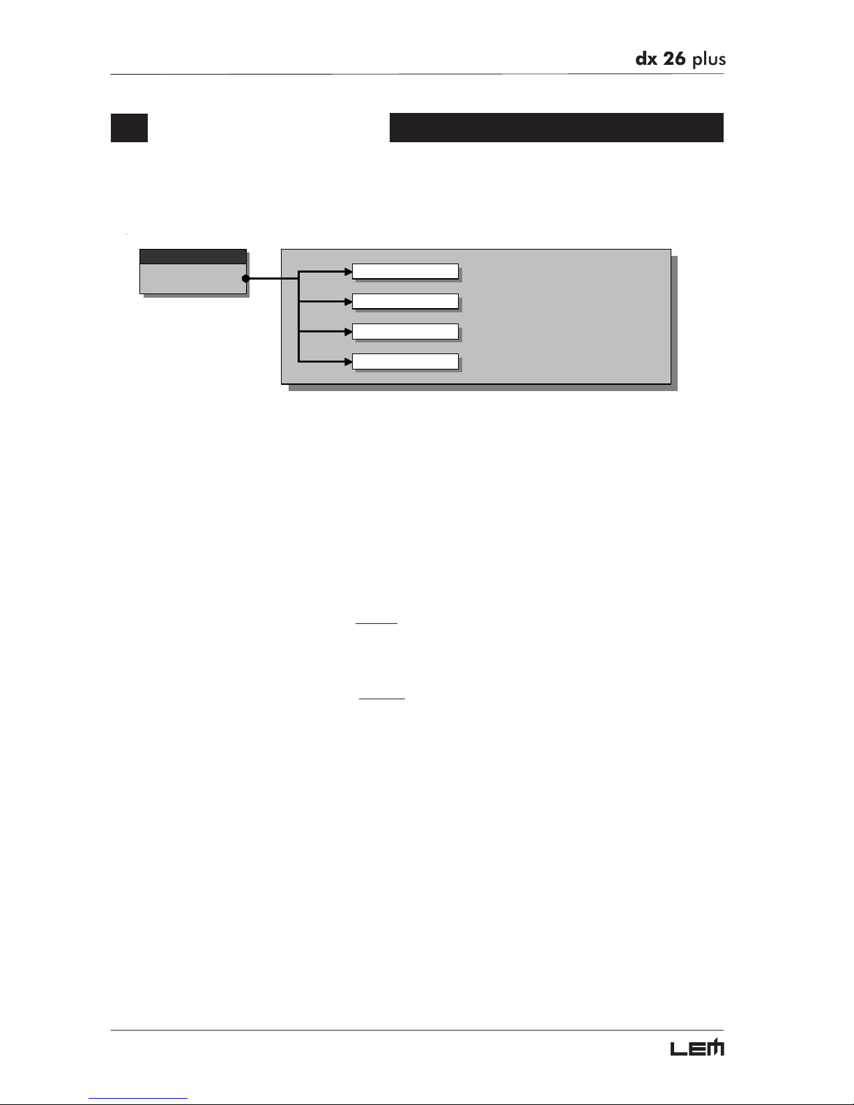
This menu allows access to the Presets’ control:
menu
PRESET
Load Preset
Store Preset
Dump Out Pre set
Incoming Dump
There are 3 distinct categories of PRESETS:
Factory PRESETS Factory-programmed storage.
Factory PRESETS can be used normally, temporarily modified, but can’t be cancelled,
overwritten or permanently modified. Factory PRESETS contain some specific settings for certain types of enclosures and all the system’s usable configurations. For this
reason they’re the ideal starting point for creating custom PRESETS.
User PRESETS Stored data that can be programmed by users.
User PRESETS are internal memory areas in which your own personal settings can be
saved.
Card PRESETS Stored data which can be programmed by users on a Multimedia Memory Card.
Card PRESETS are external memory areas in which your own personal settings can
be saved.
PRESET menu
Page 23
23
Load PRESET
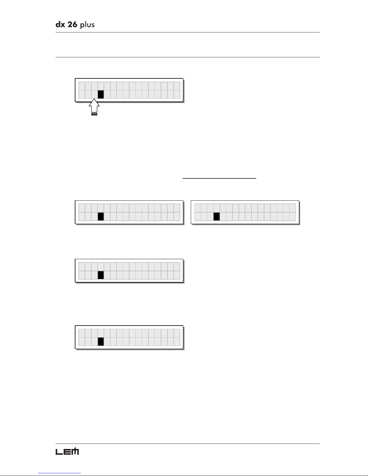
This menu page allows the required PRESET to be loaded and made operative.
Load Preset
2U 2x2
W
+2MAX
To load a PRESET:
☞ Use the DIAL to reach the required PRESET.
21 Factory PRESETS, 64 User PRESETS and 128 Card User PRESETS are available.
N.B.: since the system must always be configured, there are no empty memory areas. All the User and Card areas
not yet used by custom PRESETS are automatically occupied by the *Default* PRESET, which contains a standard
start configuration with all the values of the various parameters at zero.
Load Preset
64U *Default*
A
135 B246
64U *Default*
Scrolling through the 128 memory areas reserved for the Card when the Multimedia Memory Card isn’t
inserted, the display shows the following message:
Load Preset
128C NO C
A
RD
☞ Press ENTER.
The system returns to default status and the display shows the information on the PRESET that has just
been loaded.
A
135 B246
3F 2x3
W
N.B.: in the example, Factory PRESET #3, named “2x3W” has been loaded: its system configuration is Input A signal
assigned to outputs 1, 3 and 5; Input B signal assigned to outputs 2, 4 and 6.
Loading a PRESET, a PRESET Change command is also automatically sent to the serial ports and can
be used to automatically load a PRESET with the same number to any other DX 26 PLUS units con-
nected and enabled (see UTILITY menu - Comm. Setup submenu - PRESET Change RX option).
PRESET menu
Page 24
24
Store & Naming PRESET
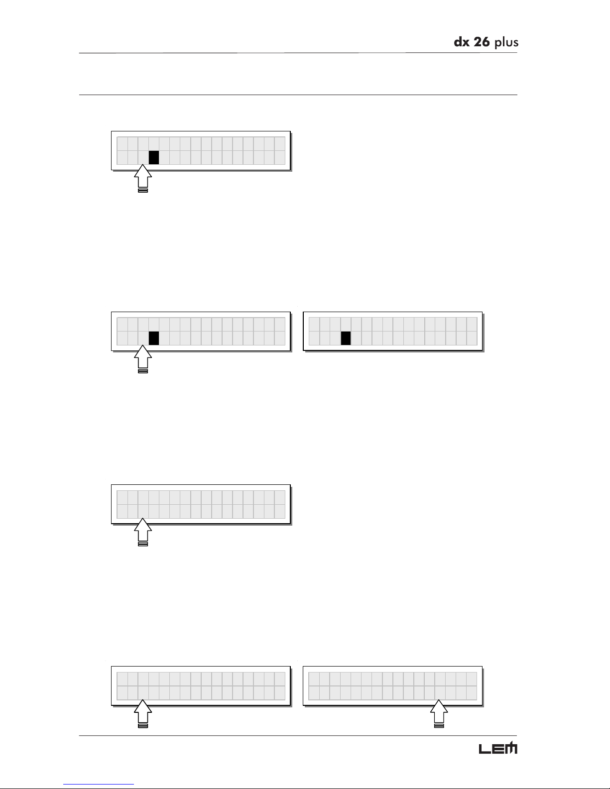
This menu page allows to create new PRESETS, i.e. to save all the current system settings.
Store Preset
2U 2x2
W
+2MAX
To save a PRESET:
☞ Use DIAL to reach the memory area in which the PRESET is to be saved.
N.B.: in this procedure, the Factory PRESET areas aren’t available, since the Factory PRESETS cannot be permanently
modified. Nevertheless remember that it is possible to load a Factory PRESET, save it in a User PRESET or Card
PRESET area, modify it as required and then store it again in the same User or Card area.
N.B.: scrolling through the memory areas, the display shows the number, type and name of the PRESETS contained in
them; scrolling through the 128 Card memory areas without the Multimedia Memory Card, a warning appears on the display:
Store Preset
3U O
p
eraHall 1
Store Preset
101C NO C
A
RD
☞ Press ENTER. The PRESET Naming page appears, by means of which it’s possible to edit the name
of the PRESET to be saved.
N.B.: if you’re in one of the 128 memory areas reserved for the Card and you remove the Multimedia Memory Card
before pressing ENTER, nothing happens: the display remains unchanged and Store PRESET procedure remains
unvaried.
The name of the “start” PRESET (i.e. of the PRESET currently loaded) is proposed as default. The
cursor takes up position on the first of the twelve character spaces available.
Preset Namin
g [
2x2W+2MAX
]
At this point:
✧ If you decide to accept and confirm the name suggested, press ENTER.
✧ If you want to abort Naming procedure (for example because you’ve chosen the wrong memory area)
and return to Store PRESET procedure, press ESC.
☞ If you want to assign a new name to the PRESET you’re storing:
- use the
WW
WW
W and
XX
XX
X keys to position the cursor on the required character
- use DIAL to enter the alphanumeric value wanted
- after finishing, press ENTER.
Preset Namin
g
[Mx2W+2MAX
]
Preset Namin
g
[M
y
Live set
]
PRESET menu
Page 25
25
Dump Out PRESET
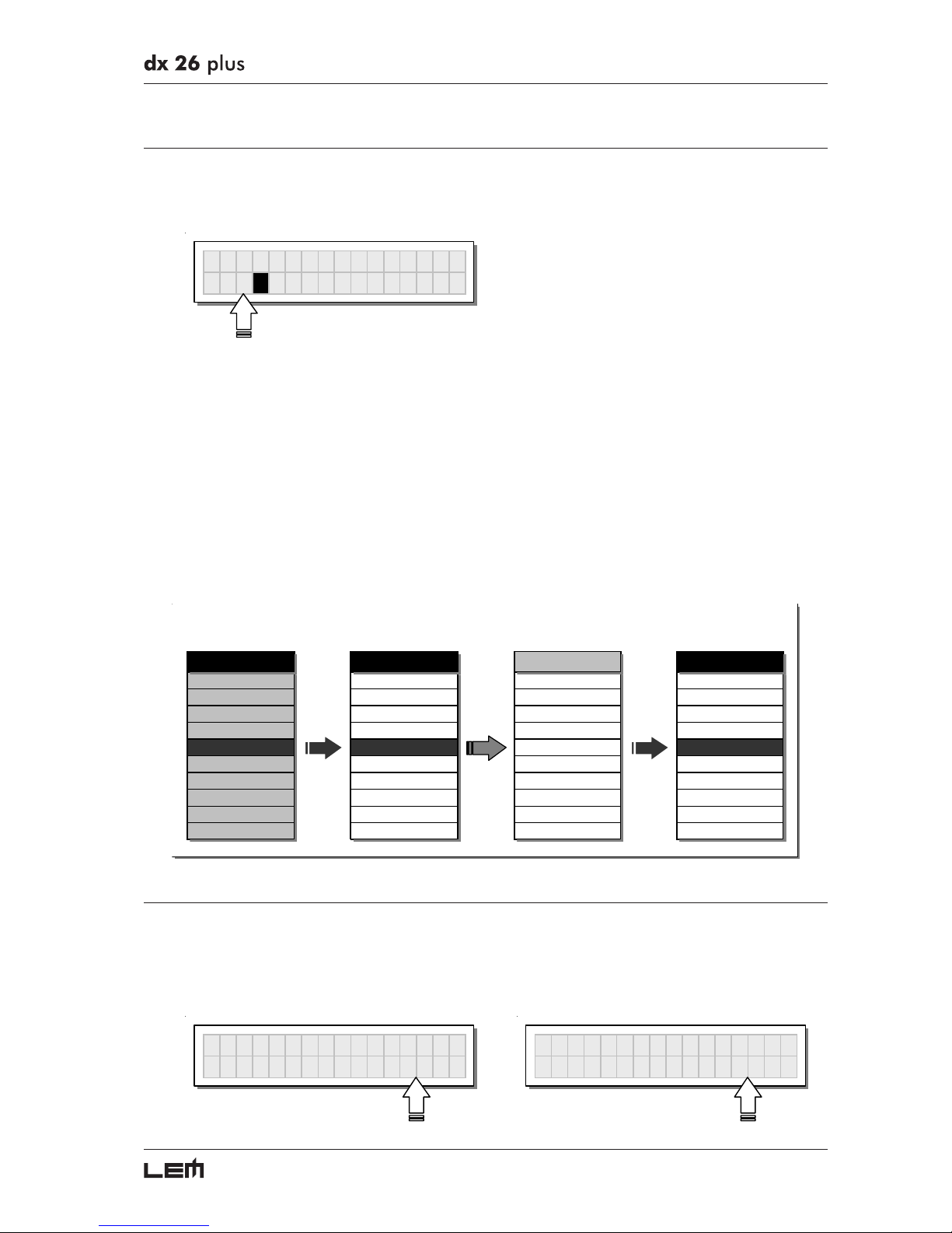
This menu page allows to download a PRESET via the serial ports.
This allows to immediately “copy” the settings of the various PRESETS of a DX 26 PLUS to another DX
26 PLUS.
Dump Out Preset
2U 2x2
W
+2MAX
To download a PRESET:
☞ Use DIAL to reach the required PRESET.
☞ Press ENTER.
N.B.: the menu page remains unchanged to allow other PRESETS to be dumped.
All the Preset’s data (name, configuration, parameter values, etc.) are immediately transmitted to the
units connected to the serial ports (other DX 26s, computers, etc.).
N.B.: in order for the transfer to have effect, the receiving units must be able to identify and accept Incoming Dump
operations.
When two or more DX 26s are connected, the PRESET sent by the transmitting DX 26 PLUS (TX)
overwrites (and therefore cancels) the existing PRESET in the same memory position of the receiving
DX 26s (RX).
DX 26 #1 DX 26 #2 DX 26 #3 DX 26 #4
Dump Out Pre se
t
Incoming Dump Incoming Dump Incoming Dump
SEND
DUMP
ACCEPT
DUMP
IGNORE
DUMP
ACCEPT
.. .. .. ..
Preset #2 #2 MySe tup #2 Side Field #2 Default
Preset #3 #3 MySe tup5 #3 Conce rt1 #3 Default
Preset #4 #4 Live Se t #4 Concert2 #4 Default
Preset #5 Preset #5 #5 Concert3 Preset #5
Preset #6 #6 Monitor #6 Concert4 #6 Default
Preset #7 #7 Monitor2 #7 Remote1 #7 Default
Preset #8 #8 Monitor3 #8 Remote2 #8 Default
Preset #9 #9 Side #9 Remote 2 #9 Default
.. .. .. ..
SERIAL PORT
SERIAL PORT
SERIAL PORT
Incoming Dump
Allows to accept or ignore the Dump of a PRESET sent from another DX 26 PLUS or from a
computer via serial ports. Settings can be:
Ignore the data received via the serial ports. Accept the data received via the serial ports.
Incomin
g
Dum
p
I
g
nore
Incomin
g
Dum
p
A
ccept
PRESET menu
Page 26
26
DELAY Menu
This menu allows to work on the system’s delay lines.
menu
DELAY
Input Delay
Output Delay
para mete rs
para mete rs
parameters
In these pages, the number of the parameters and how they are presented varies according
to the configuration of the PRESET and according to Ganging and Units settings (UTILITY menu). In fact, these pages
only show the parameters that can actually be used, in the most suitable form of editing.
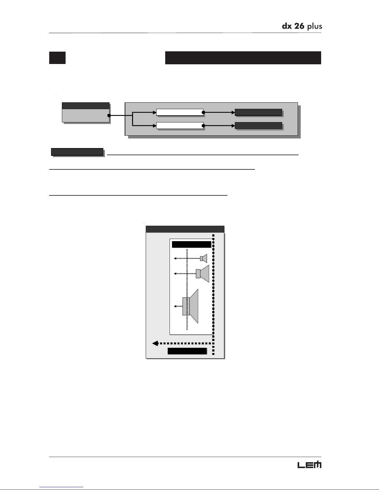
The practical differences between Delay Input and Delay Output
A Delay is only a processor by means of which a signal is deliberately delayed by a programmable length
of time. From a technical point of view, the Delays applied to the inputs and outputs are equivalent.
Nevertheless, their application is different:
OUTPUT DELAY
INPUT DELAY
DELAY
Input Delay delays the signal of an input (or the sum of the inputs) before sending it to the routing system. In this
way, all the outputs which depend on that input are delayed by the same length of time.
Also called Master Delay, input Delay is mainly used to compensate for the effects dues to the distance
between the various speaker enclosures or between various blocks of a complex sound system (for
example in large concert halls, stadiums, etc.), thus achieving virtual alignment.
Output Delay only delays the signal of a specific output.
Also called Channel Delay, output delay is mainly used to compensate for the distance between different
blocks of the same sound system (for example clusters) or to correct internal alignment of a speaker
enclosure’s components.
DELAY Menu
Page 27
27
Input Delay
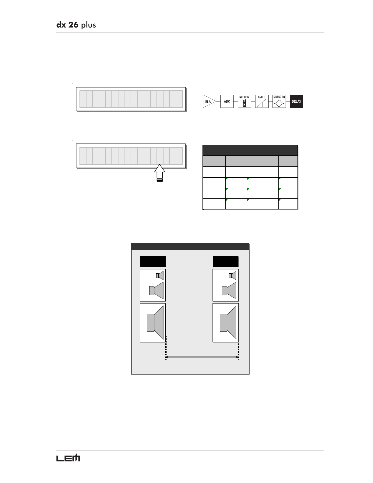
This menu page allows to adjust the delay lines of Input A, Input B and SUM.
´
Input Dela
y
The values can be set in the following ranges:
IN
A
DELAY
77ms
unit step
m0.0÷900.0 0.5
mm 0 ÷ 900000 7
ms 0 ÷ 2621 1
us 0 ÷ 2621438 21
range
INPUT DELAY
The measurement unit can be chosen with the function Delay Unit (UTILITY menu - Units submenu).
INPUT DELAY
INPUT A
MAIN PA
91ms - 31,5m (20 °C)
INB DEL A Y = 9 1 m sINA DELAY = 0
INPUT B
DELAYED
DELAY Menu
Page 28
28
Output Delay
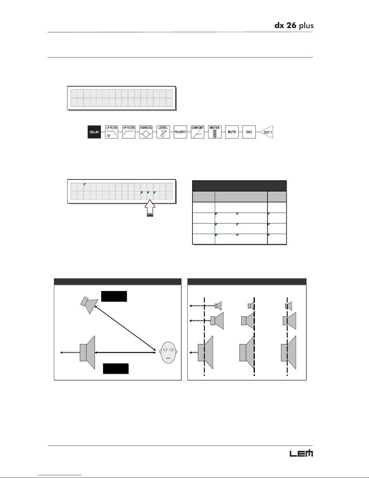
This menu page allows to adjust the delay lines of outputs 1, 2, 3, 4, 5 and 6.
´
Output Dela
y
The values can be set in the following ranges:
OP1 DELAY
292us
unit step
m0.0÷100.0 0.5
mm 0 ÷ 100000 7
ms 0 ÷ 291 1
us 0 ÷ 291271 21
OUTPUT DELAY
range
The measurement unit can be chosen with the function Delay Unit (UTILITY menu - Units submenu).
18ms (6,5 m)
OP1 DE LAY =
14ms (5m)
OUTPUT DELAY
OUTPUT 1
HIGH
OUTPUT 3
LOW
OP3 DELAY =
4ms
Loudspeaker
Components
Delayed Virtual
Alignment #2
OUTPUT DELAY
Delayed Virtual
Alignment #1
DELAY Menu
Page 29
29
EDIT menu
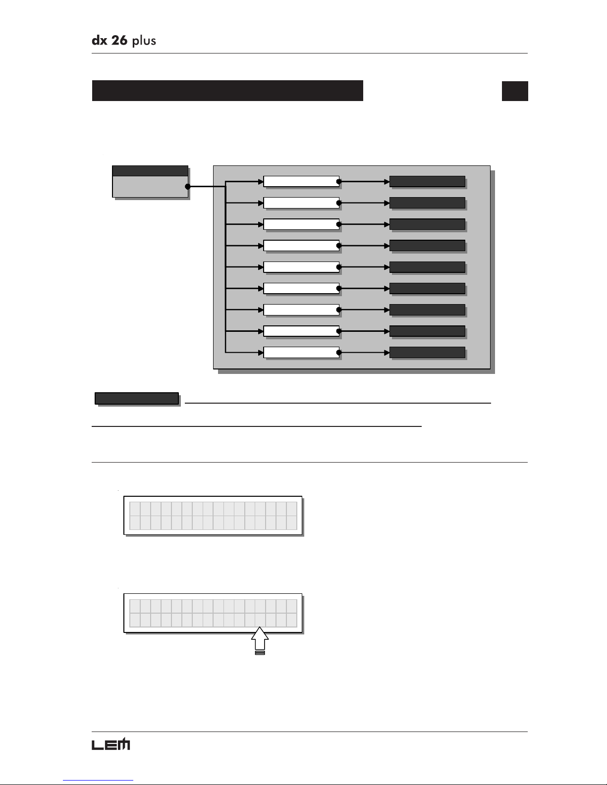
This menu allows to edit the system’s actual audio parameters.
menu
EDIT
Input Gain
Input EQ
Noi se Gate
Xover
Output EQ
Output Gain
Output Pol .
para meters
para meters
para meters
para meters
para meters
para meters
para meters
Output Cmp/Limit para meters
Input GATE para meters
parameters
In these pages, the number of the parameters and how they are presented varies according
to the configuration of the PRESET and according to Ganging and Units settings (UTILITY menu). In fact, these pages
only show the parameters that can actually be used, in the most suitable form of editing.
Input Gain
Input gain control.
´
Input Gain
Allows to adjust the amplification of the signal fed in through Inputs A and B.
Editing values are in the range +6dB ÷ -30dB, with 0.5dB steps.
IN
AGA
IN
-2.5dB
N.B.: setting the input signal of a digital unit is particularly important, much more than on an analog unit, as any saturation
of the A/D converter due to an excessively high input signal causes a typical particularly distinct noise. To achieve a
good signal/noise ratio, i.e. an up-front distortion-free signal, feed a signal in on the DX 26’s input and watch the INPUT
LEVEL A-B LED ladders. Keep the signal quite high, but make certain the red CLIP LED doesn’t light up continually.
EDIT menu
Page 30
30
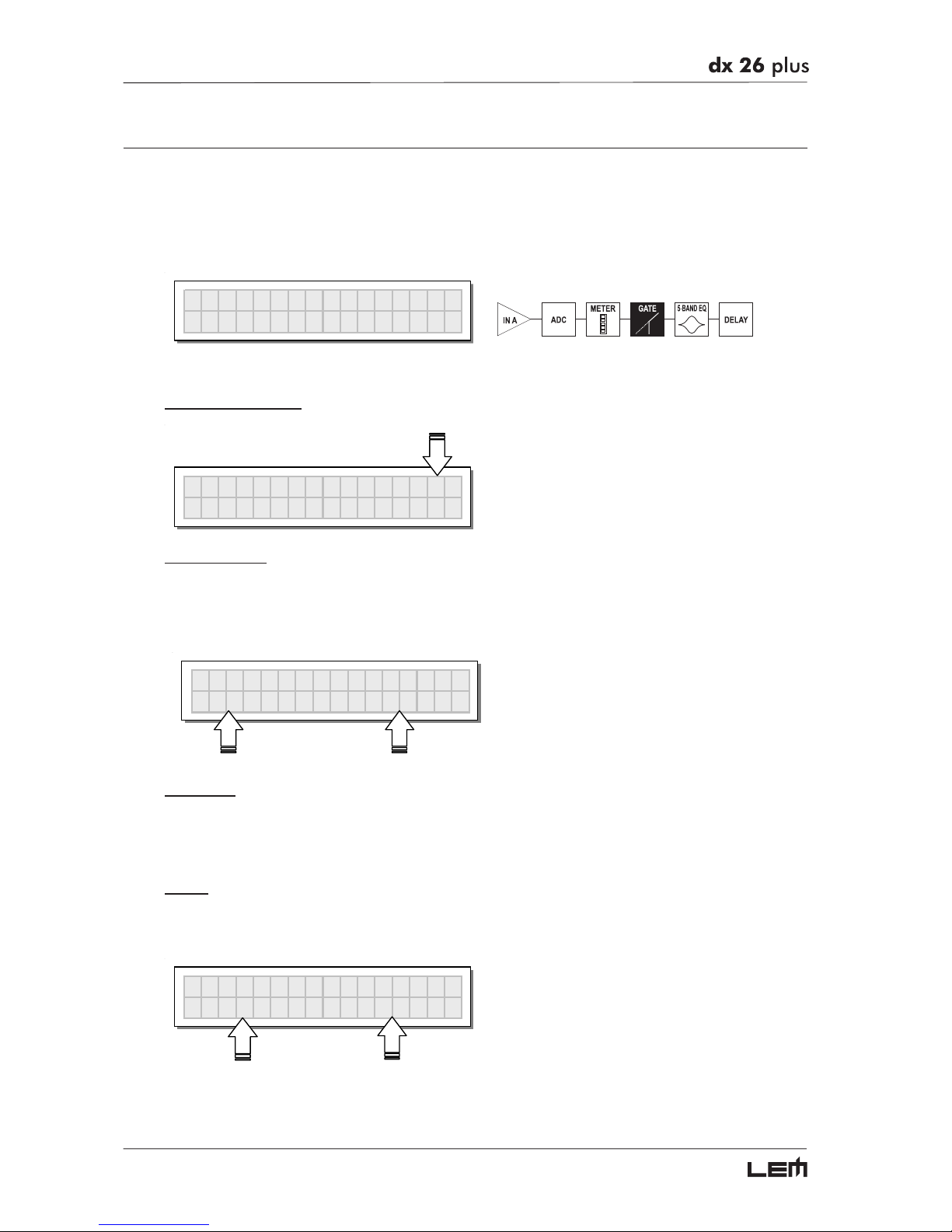
Input Noise Gate
Noise reduction filter onthe inputs.
Aloows to cut or reduce the background noise generated by the unit connected to the processor’s
inputs (the mixer, for example). The filter is active when the input signal is below a certain threshold
and reduce its level cutting the undesired background noises.
´
Noise Gate
The following editable parameters are available, in two different pages:
Noise Gate ON/OFF
IN
A
Gate On
A
T1.0ms RL0.50S
Reaction times
Allows to set the Noise Gate attack and release times.
ATTACK (AT) is the time needed by the filter to bring back the signal to its normal level when it
goes above the threshold.
RELEASE (RL) is the time needed by the filter to cut the signal once it goes below the threshold.
IN
A
Gate On
A
T1.0ms RL0.50S
Threshold
Allows to set the threshold level: if the signal goes below this threshold the Noise Gate reduces the
level.
The editing values are within the following ranges: +8dBu ÷-60dBu, with 2dBu steps
Range
Allows to set the amount of the signal level reduction.
The editing values are within the following ranges: 0dBu ÷-80dBu, with variable steps
IN
A
Gate On
THR-60.0 RG-80.0
EDIT menu
Page 31
31
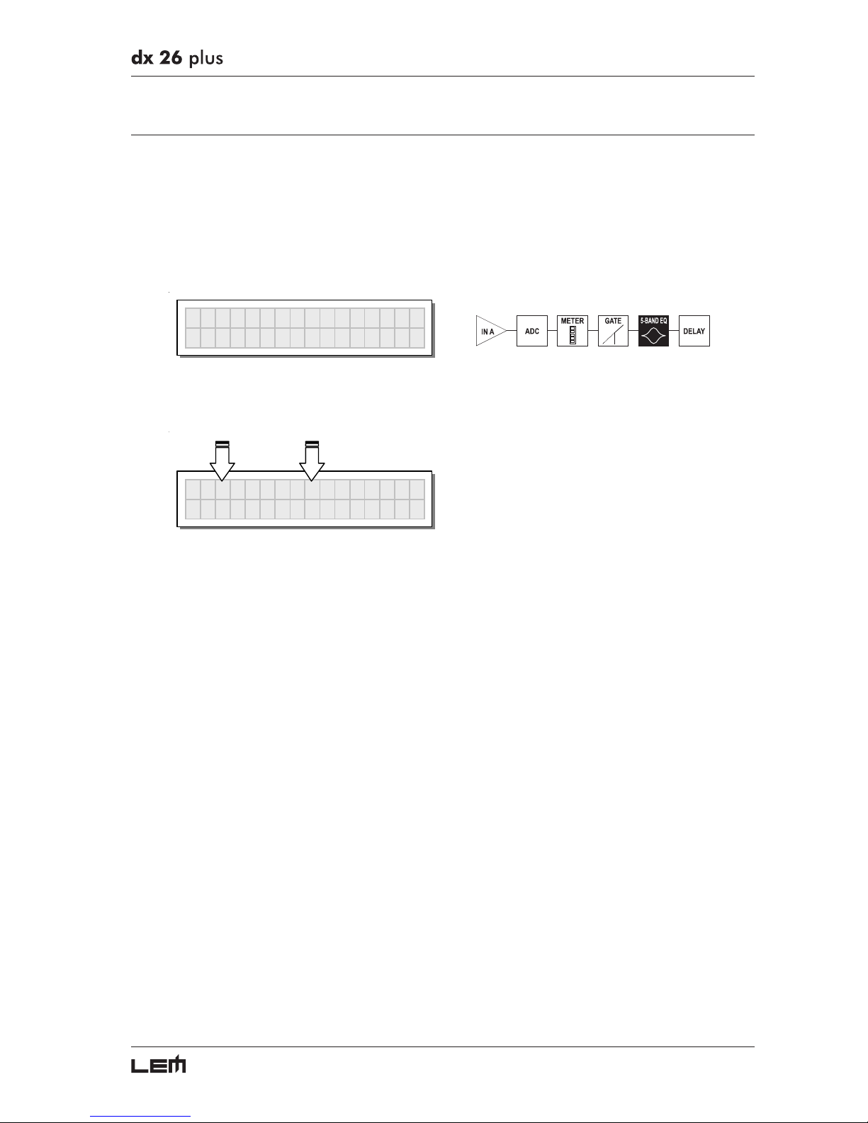
Input EQ
Input equalizer with 5 parametric filters.
Allows to alter the overall tone of the signal connected to the respective input.
Also called Master EQ, the equalization of the input signal effects all the outputs connected to the input
and the input SUM.
This component’s characteristic quality and programmability (identical to the output Equalizer) enable it
to be used so effectively and flexibly as to make the use of graphic equalizers often unnecessary.
Input EQ
Each equalizer has 5 pages (one for each filter), showing the name of the input it affects and the
number of the filter.
INA EQ1 Peak
2k00 1.0 -5.0
Example: Input A - Filter 1
EDIT menu
Page 32
32
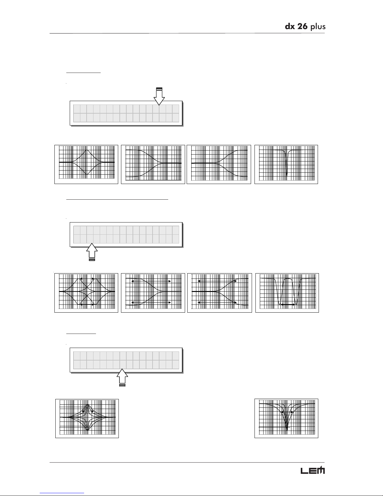
The following editable parameters are available for each filter:
Type of filter
Allows to choose among Peaking, Low or High Shelving with a slope of 6 or 12 dB per octave and Notch filter.
INA EQ1 Peak
2k00 1.0 -5.0
Peaking Low Shelving High Shelving Notch
-20 dB
-15 dB
-10 dB
-5 dB
0 dB
5 dB
10 dB
15 dB
20 dB
10 Hz 100 Hz 1.000 Hz 10.000 Hz 100.000 Hz
-20 dB
-15 dB
-10 dB
-5 dB
0 dB
5 dB
10 dB
15 dB
20 dB
10 Hz 100 Hz 1.000 Hz 10.000 Hz 100.000 Hz
-20 dB
-15 dB
-10 dB
-5 dB
0 dB
5 dB
10 dB
15 dB
20 dB
10 Hz 10 0 Hz 1.000 Hz 10.000 Hz 100.000 Hz
-40 dB
-35 dB
-30 dB
-25 dB
-20 dB
-15 dB
-10 dB
-5 dB
0 dB
5 dB
10 Hz 100 Hz 1000 Hz 10000 Hz 100000 Hz
Centre Frequency / Cutoff Frequency
Allows to choose the centre frequency of the Peaking curve and Notch filter, or the cutoff frequency of
Shelving curves.
INA EQ1 Peak
2k00 1.0 -5.0
Peaking Low Shelving High Shelving Notch
-20 dB
-15 dB
-10 dB
-5 dB
0 dB
5 dB
10 dB
15 dB
20 dB
10 Hz 100 Hz 1000 Hz 10000 Hz 100000 Hz
-20 dB
-15 dB
-10 dB
-5 dB
0 dB
5 dB
10 dB
15 dB
20 dB
10 Hz 100 H z 1.000 Hz 10.000 Hz 100.000 Hz
-20 dB
-15 dB
-10 dB
-5 dB
0 dB
5 dB
10 dB
15 dB
20 dB
10 Hz 100 Hz 1.000 Hz 10.000 Hz 100.000 Hz
-40 dB
-35 dB
-30 dB
-25 dB
-20 dB
-15 dB
-10 dB
-5 dB
0 dB
5 dB
10 Hz 100 Hz 1000 Hz 10000 Hz 100000 Hz
Bandwidth
Allows to choose the width in octaves of the Peaking or Notch type curve. It’s not used with Shelving curves.
INA EQ1 Peak
2k00 1.0 -5.0
Peaking Notch
-20 dB
-15 dB
-10 dB
-5 dB
0 dB
5 dB
10 dB
15 dB
20 dB
10 Hz 100 Hz 1000 Hz 10000 Hz 100000 Hz
-40 dB
-35 dB
-30 dB
-25 dB
-20 dB
-15 dB
-10 dB
-5 dB
0 dB
5 dB
10 Hz 100 Hz 1000 Hz 10000 Hz 100000 Hz
EDIT menu
Page 33
33
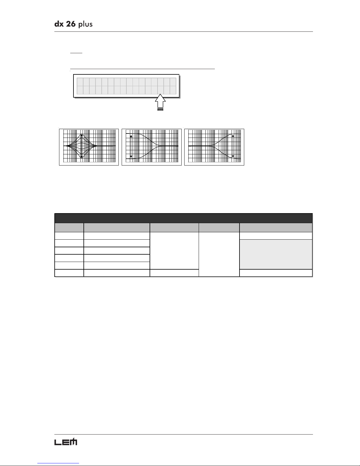
Gain
Allows to control the boost or cut of the selected frequencies.
It’s not used with the Notch Filter, which has a fixed cut.
INA EQ1 Peak
2k00 1.0 -5.0
Peaking Low Shelving High Shelving
-20 dB
-15 dB
-10 dB
-5 dB
0 dB
5 dB
10 dB
15 dB
20 dB
10 Hz 100 Hz 1.000 Hz 10.000 Hz 100.000 Hz
-20 dB
-15 dB
-10 dB
-5 dB
0 dB
5 dB
10 dB
15 dB
20 dB
10 Hz 100 Hz 1.000 Hz 10.000 Hz 100.000 Hz
-20 dB
-15 dB
-10 dB
-5 dB
0 dB
5 dB
10 dB
15 dB
20 dB
10 Hz 100 Hz 1.000 Hz 10.000 Hz 100.000 Hz
The values can be set in the following ranges:
NAME TYPE GAIN FREQ WIDTH
Peak Peaking 0.05 ÷ 3.00 oct
(step 0.05 oct)
LoSh 6 Low Shelving 6dB/oct
LoSh 12 Low She lving 12dB/oct
HiSh 6 High Shelving 6dB/oct
HiSh 12 High Shelving 12dB/oct
Notch Notch Filter - 45dB
(fix)
0.05 ÷ 3.00 oct
(step 0.05 oct)
5-BAND FULL PARAMETRIC EQ
±15dB
(step 0.5dB)
15.6Hz ÷ 16kHz
EDIT menu
Page 34
34
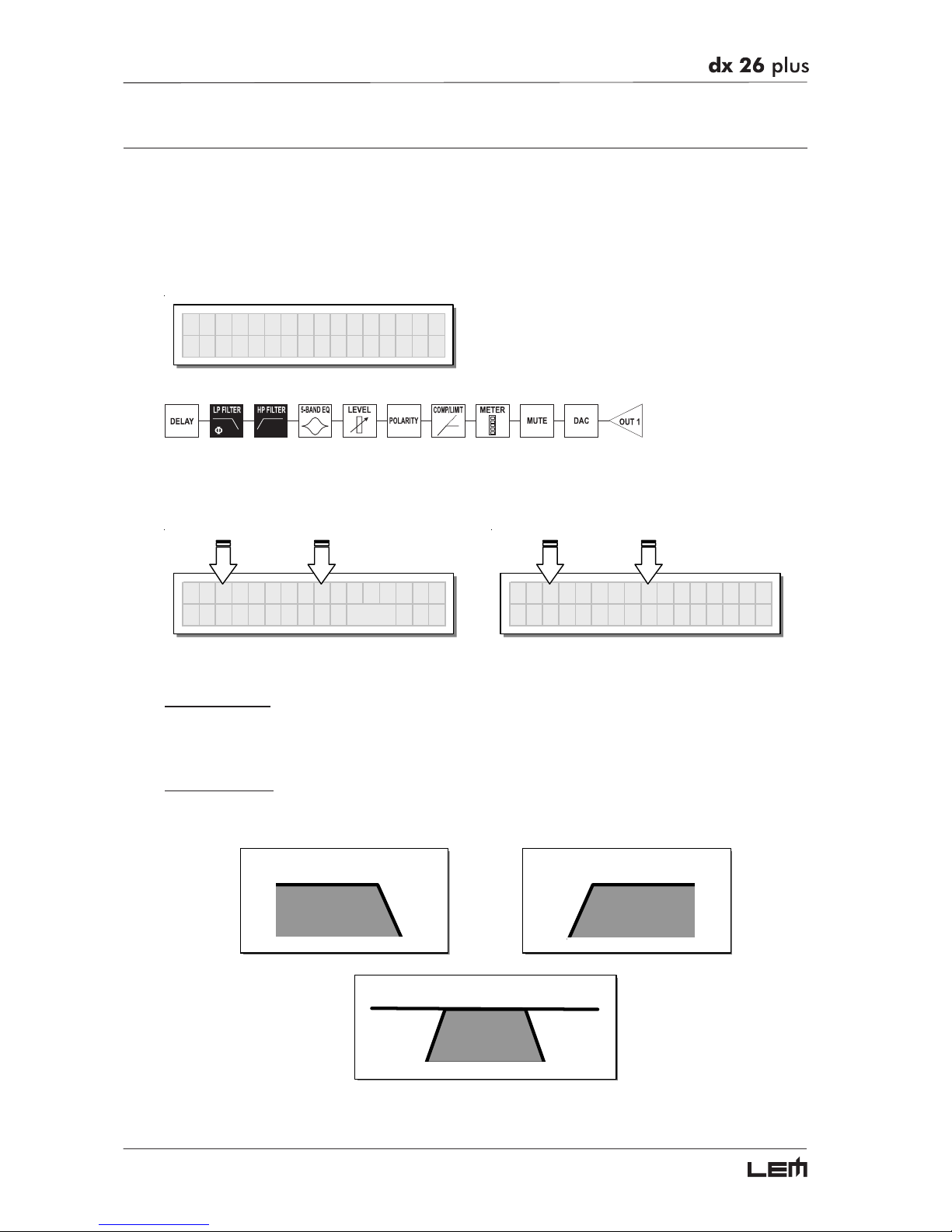
Xover
Low-pass and high-pass filters.
Made up of a combination of a low-pass filter and high-pass filter, the crossover allows to divide the
audio signal into segments that can be used by the individual sections of a sound system (for example
High, Mid & Low).
Xover
Each Xover has 2 slightly different pages (one for each filter), where the name of the output it affects
and the type of filter are shown.
OP1 LPF Thru
1k00Hz
Φ
O°
OP1 HPF Thru
1k00Hz
Output 1 - Low Pass Filter Output 1 - High Pass Filter
Low Pass Filter
The low-pass filter allows all the frequencies below a specific frequency to pass, whereas it cuts all the
frequencies above it.
High Pass Filter
The high-pass filter allows all the frequencies above a specific frequency to pass, whereas it cuts all the
frequencies below it.
LPF
HPF
HPFLPF
Signal segment obtained with the combination of LPF and HPF.
EDIT menu
Page 35
35
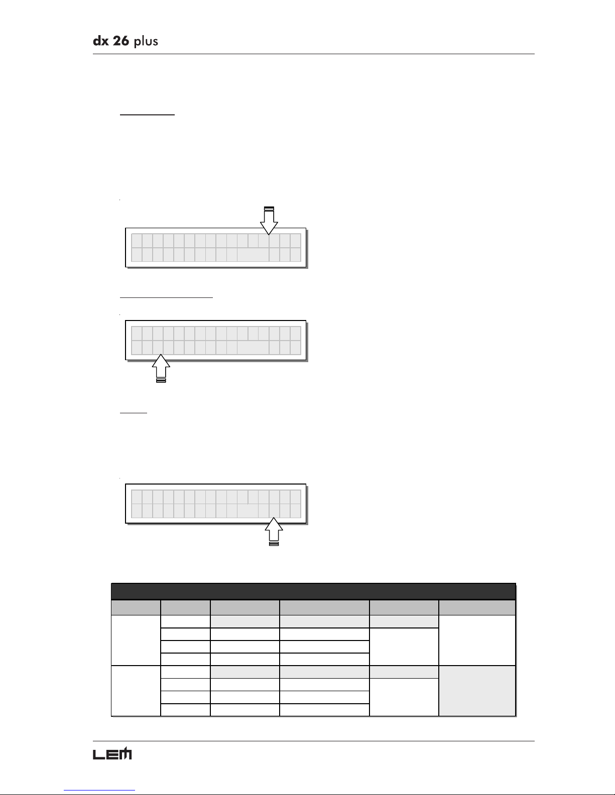
Each filter has the following editable parameters:
Type of filter
Allows to choose three different types of filter and different attenuation slopes:
Butterworth (But) at 6, 12, 18 or 24dB per octave,
Bessel (Bes) at 12, 18 or 24dB per octave,
Linkwitz-Riley (LR) a 12, 24 or 48dB per octave.
By setting the Thru value, the filter is disabled and the signal passes without its frequency being al-
tered.
OP1 LPF Bes 24
1k00Hz
Φ
O°
Crossover frequency
Allows to choose the filter cutoff frequency.
OP1 LPF Thru
1k46Hz
Φ
O°
Phase
Allows fine control (in 5° steps) of the signal’s phase.
The effect of this control is summed with that of the Output Polarity function (0°÷180°).
In this way it’s possible to adjust the phase of each individual output with 5° steps through a full 360°.
N.B.: this control is only in the Low-Pass Filter window.
OP1 LPF Thru
1k00Hz
Φ
18O°
The values can be set in the following ranges:
NAME TYPE SLOPE FREQ PHASE
Thru
But Butterworth 6, 12, 18, 24 dB/oct
Bes Bessel 12, 18, 24 dB/oct
LR Linkwitz-Riley 12, 24, 48 dB/oct
Thru
HiSh 6 Butterworth 6, 12, 18, 24 dB/oct
HiSh 12 Bessel 12, 18, 24 dB/oct
Notch Linkwitz-Riley 12, 24, 48 dB/oct
XOVER
LPF
HPF
15.6Hz ÷ 16kHz
15.6Hz ÷ 16kHz
0° ÷ 180°
(step 5°)
EDIT menu
Page 36
36
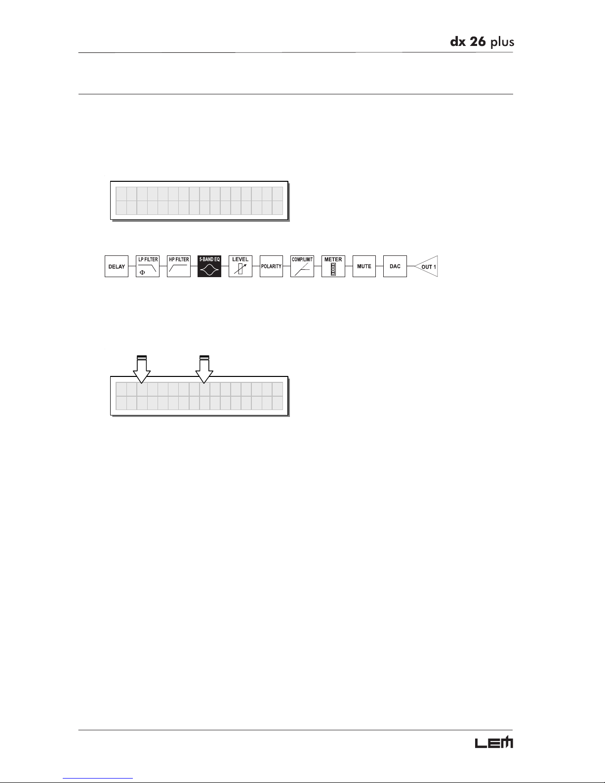
Output EQ
Output equalizer with 5 parametric filters.
Also called Channel EQ, allows to alter the tone of each individual output.
The characteristics of quality and programmability are identical to those of the Input Equalizer and
enable this unit to be used extremely effectively and flexibly.
Output EQ
Each equalizer has 5 pages (one per filter), indicating the name of the output it effects and the number of the filter.
OP1 EQ1 Peak
2k00 1.0 +1.5
Example: Output 1 - Filter 1
Since technical specifications and editing fields of the Output EQ are identical to those of the Input EQ,
please refer to INPUT EQ section for descriptions.
EDIT menu
Page 37
37
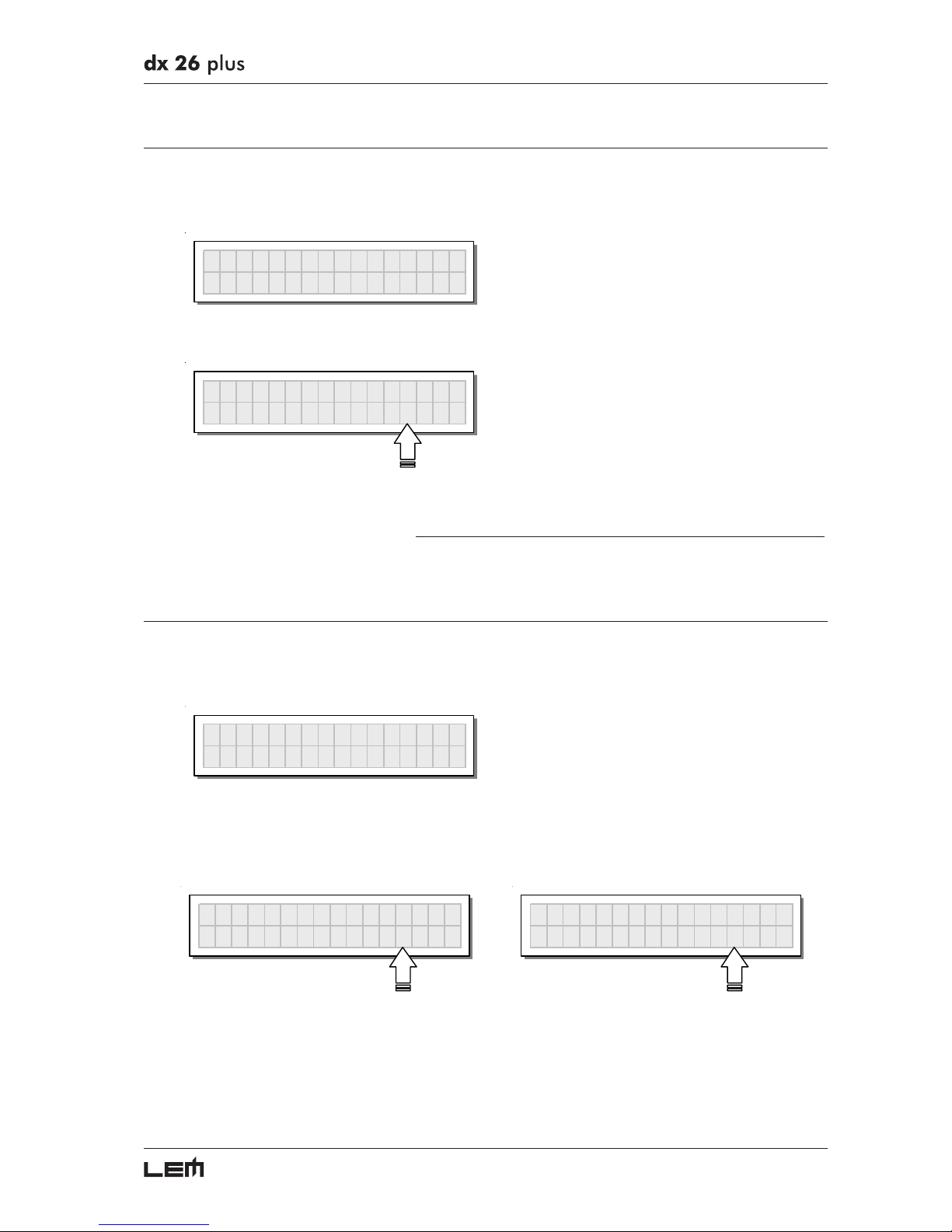
Output Gain
Output level control.
Allows to adjust the signal level of each individual output.
Output Gain
Editing values are between +6dB ÷ -30dB, with 0.5dB steps.
OP1 GAIN
-6.5dB
N.B.: the level of each output is shown by the respective OUTPUT LEVEL LED ladder. To avoid distortion, don’t let
the red CLIP LED light up. As automatic protection, you can also enable the LIMITER (EDIT menu) on the outputs
that require it. In this case, remember that enabling the LIMITER changes the display mode on the relative LED ladder:
in fact, the level shown is no longer the “absolute” output level, but the level of the signal in relation to the LIMITER
threshold.
Output Pol.
Controls the outputs’ polarity.
Allows to invert the phase of the signal of individual outputs.
Output Pol.
Editing values are:
Normal: leaves the phase unchanged Reverse: shifts the phase through 180°, inverting it.
OP1 POLARITY
Normal
OP1 POLARITY
Reverse
The effect of this control is summed with that of the
ΦΦ
ΦΦ
Φ
parameter of the LPF filter (Xover - EDIT menu),
which operates with 5° steps in a range of between 0° and 180°.
In this way it’s possible to set the phase of each individual output with 5° steps within a complete 360°
revolution, a very useful function when assembling arrays of speaker enclosures, in the control of the
interpolation between various enclosures or between sections of the same system.
EDIT menu
Page 38
38
Output Compressor/Limiter
Output level compressor/limiter.
Allows to keep the signal of each individual output within a set level.
Can be used effectively to protect the components of a sound system or to obtain compression effects
and to increase the signal dynamics while keeping it within certain limits.
´
Output CompLim
The following editable parameters are available:
Reaction times
Allows to choose between 3 types of Limiter reaction speed.
In fact, these are attack and release times that are optimised so that the Limiter reacts more or less
rapidly when the signal exceeds or drops below the threshold:
☞ Fast short times, suited to rapid Limiter operation. Normally more suited to outputs dedicated
to high frequencies.
☞ Normal intermediate times, suited to the majority of applications. Normally more suited to outputs
dedicated to mid frequencies or full-range systems.
☞ Slow long times, suited to avoiding rapid repeated level jumps (pump effect). Normally most
suited to outputs dedicated to low frequencies.
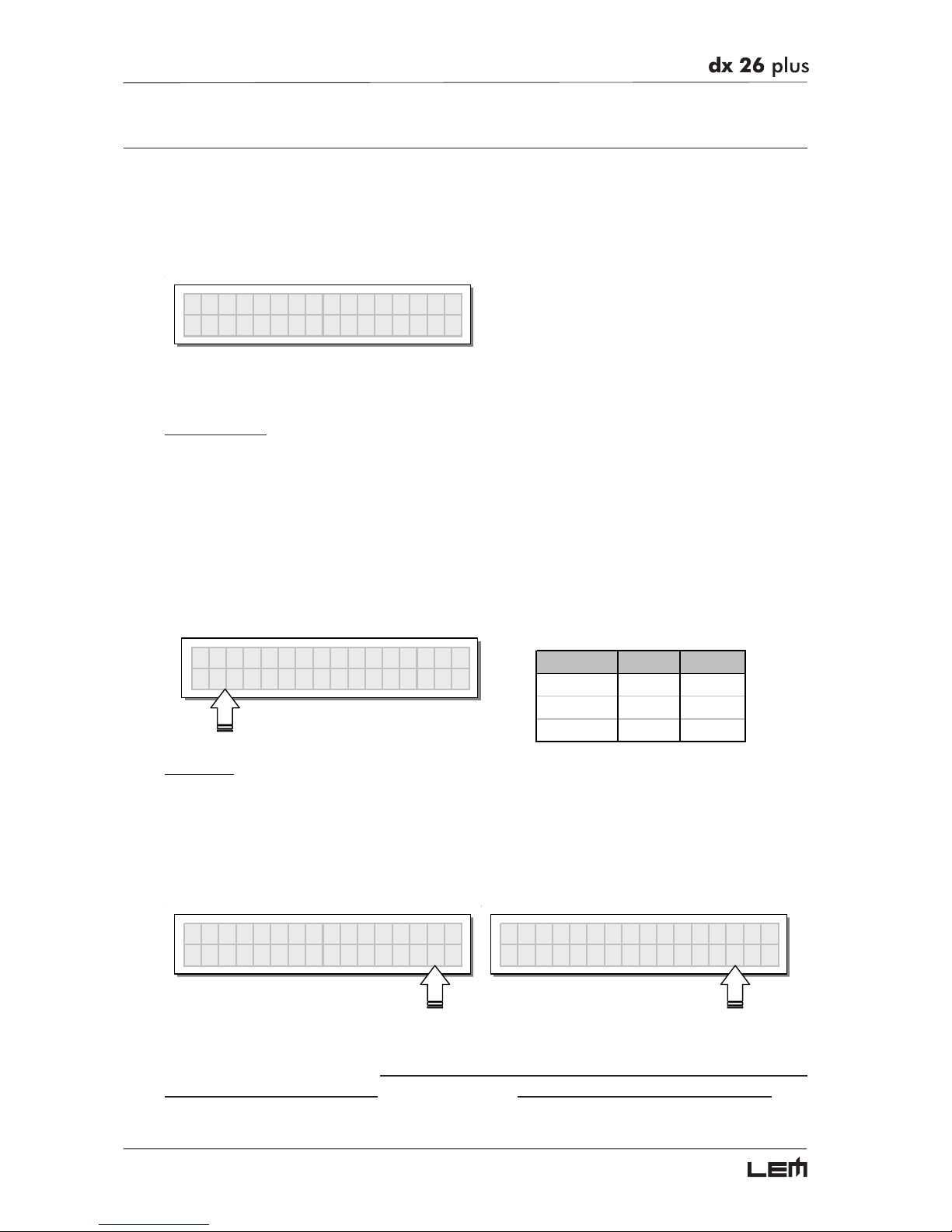
OP1 CompLim
Fast 3.0 Off
COMP/LIMIT ATTACK RELEASE
FAST 1 ms 10 ms
NORMAL 8 ms 80 ms
SLOW 45 ms 450 ms
Threshold
Allow to set the level above which the Compressor/Limiter intervenes (limiting the signal) and below
which it leaves the signal unchanged.
The editing values are within the following ranges: +19.8dBu ÷ -10dBu, with 0.2dBu steps
7.574V ÷ 0.245V with variable steps
The measurement unit can be chosen with the Lim. Thresh. Unit function (UTILITY menu - Units
submenu). The Off value disables the Compressor/Limiter, whereas any other value enables it.
OP1 CompLim
Slow 1.1 5.8
OP1 CompLim
Slow 20.0 Off
IMPORTANT! Enabling the Compressor/Limiter on a specific output also changes the way in which the
level is displayed on the corresponding LED ladder: in fact, the level shown on this ladder is no longer
the “absolute” output level, but the level of the signal at -24dB, -12dB, -6dB compared to the COM-
PRESSOR/LIMITER’s threshold (orange LIMIT LED), no matter what the threshold value is
EDIT menu
Page 39
39
Ratio
Allows to set the compression ratio, that is to say how the signal exceeding the trheshold has to be
reduced.
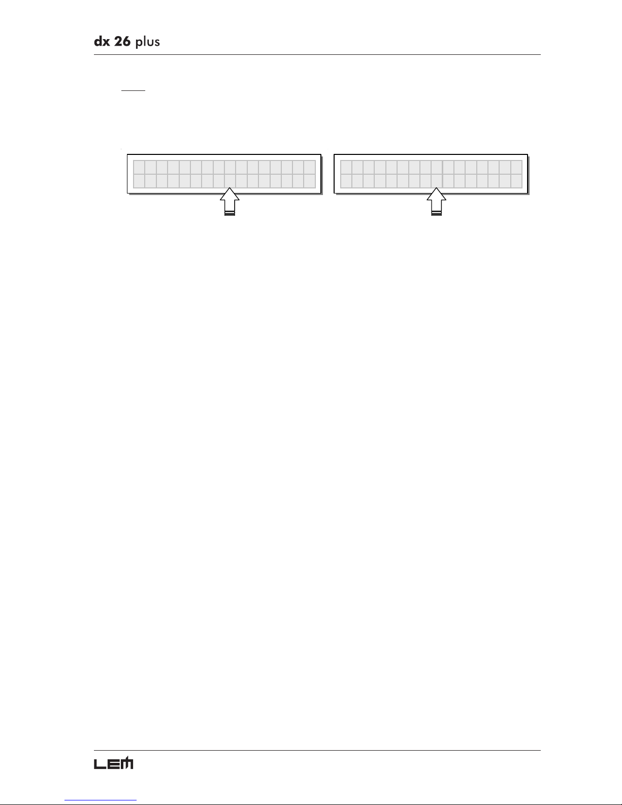
The editing values are the following: Lim. 20.0 10.0 8.0 6.0 5.0 4.0 3.5 3.0 2.5 2.0 1.7 1.5 1.3 1.1
OP1 CompLim
Fast 3.0 Off
OP1 CompLim
Fast Lim. Off
The Lim. value corresponds to the maximum compression ratio (all the signal exceeding the threshold
is cut) and in this condition the processors acts as a LIMITER.
The other values allow to reduce the signal with a ratio from 1:20.0 (high compression) to 1:1.1 (low
compression) in order to obtain different compression effects according to the kind of signal and to the
kind of application.
EDIT menu
Page 40
40
UTILITY Menu
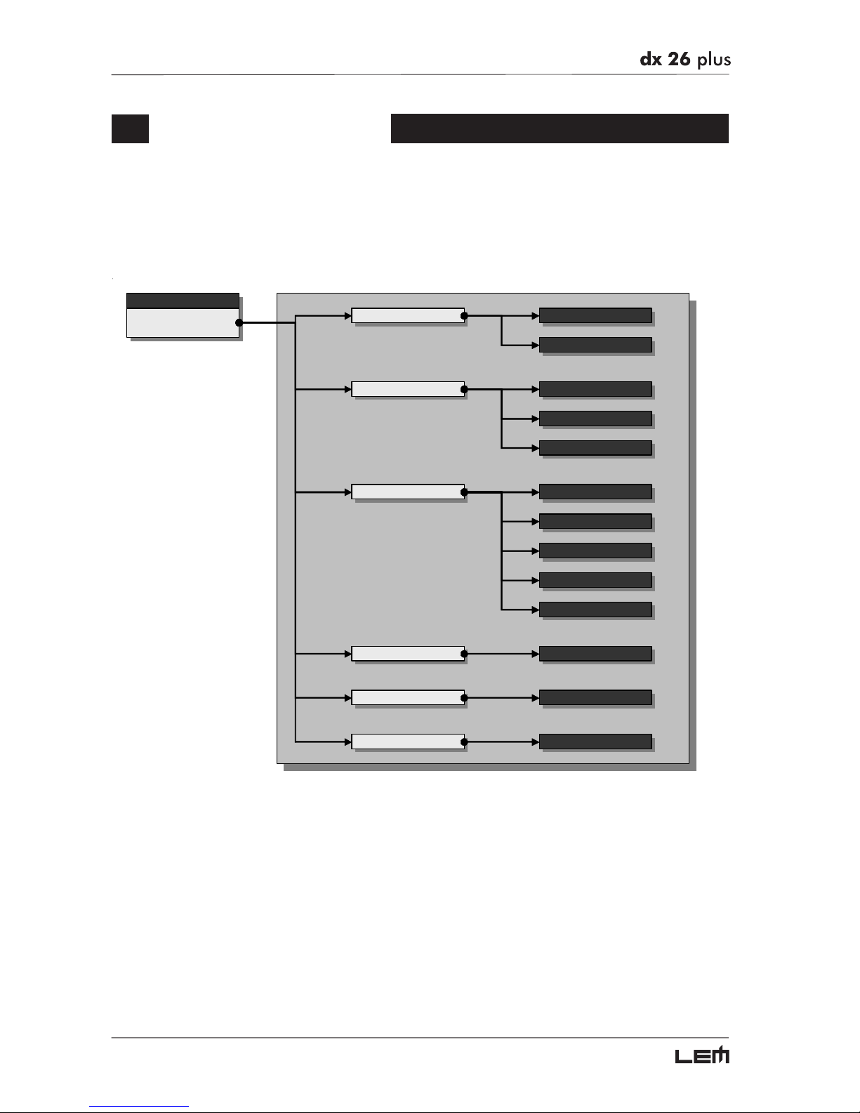
This menu comprises a series of submenus that allow to set a series of system options and access
certain utilities, such as the control of the Multimedia Memory CARD or protection against
accidental or unauthorized changes:
menu
UTILITY
Comm. Setu
p
Preset Change RX
Gangin
g
Input Gangin
g
Output Gangin
g
Delay UnitUnits
Lim. Thresh. Unit
Temperature Unit
Input SelectMisc. Setu
p
Output Meters
Temperature
Wake U
p
LCD Contrast
Lock Lock
Memory Card Format Card
UTILITY menu
Page 41
41
GANGING SUBMENU
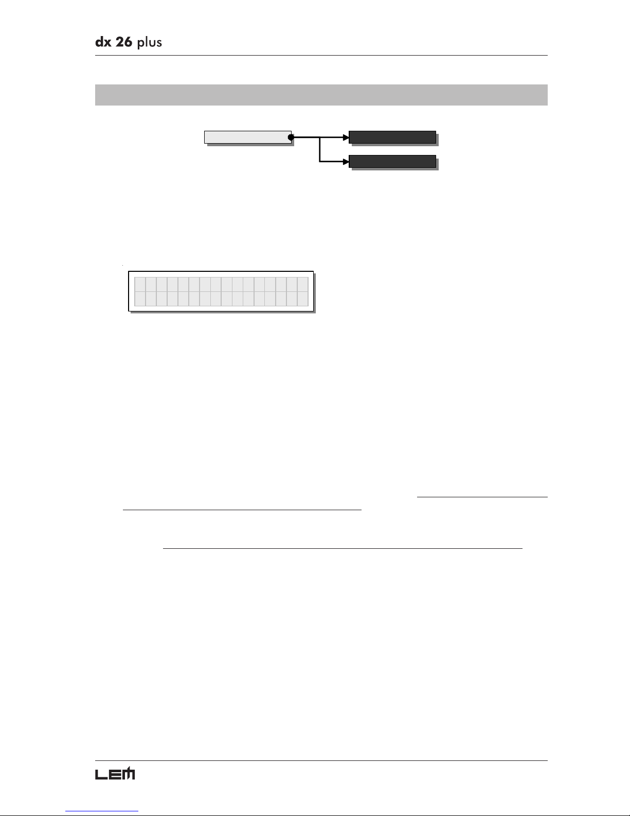
Ganging Input Ganging
Output Ganging
This submenu allows to group together the treatment of similar inputs and/or outputs.
Similar is intended as meaning elements which have the same properties and/or the same structure.
For example, the right and left sections of a stereo system are similar, as they are made up
symmetrically of the same quantity and type of elements (the same components for High, Mid and
Low frequencies).
Gangin
g
The practical use of the Ganging function consists in the possibility of editing with identical values
the parameters of similar elements, carrying out single (instead of double) operations.
For example, it’s possible to set the same Delay value or equalization on both inputs with just one
operation; or set identical Xover parameters for the various outputs fed to a stereo sound system;
or yet again, enable the LIMITER simultaneously on the two outputs dedicated to two mono stage
monitors.
The system automatically recognizes incompatible elements contained in the various configurations
and only enables the Ganging function where it can effectively be used. Therefore, the Ganging
function doesn’t have any effect on the MONO setups. The Ganging function can be enabled
separately for both groups of input and groups of outputs.
IMPORTANT: precisely for its characteristics, the Ganging function affects the way in which the
relative parameters audio are edited or represented:
As soon as Inputs and/or Outputs are ganged, the various menu pages only show the values that
can actually be used. This however doesn’t mean that the values change immediately. On the
contrary, the values remain unchanged (even if not shown) until new values are entered. Only
at that point ganged Inputs and/or Outputs assume the same value with just one operation.
For example, even if the display shows that “Input A&B” are ganged in the page with a certain parameter, the value
shown remains that of Input A until a new value is entered, as Input B doesn’t automatically assume the values of
Input A.
To check this:
1. set Input Gangin=Off, load the *Default* PRESET, set INA Delay=1 and INB Delay=0;
2. set Input Gangin=On, return to the Input Delay menu: the display shows INA&B Delay=1:
a. if you leave the value unchanged and once again set Input Gangin=Off
going back to the Input Delay menu, the display shows INA Delay=1 and INB Delay=0 (“original” values).
b. if you change the value, for example INA&B Delay=3, and you once again set Input Gangin=Off
going back to the Input Delay menu, the display shows INA Delay=3 and INB Delay=3 (“new” values).
This condition is used to avoid accidental or temporary enabling of the Ganging function from changing the values of
all the stored PRESET. The rule can be summed up as follows: “only the values that have to be intentionally changed
are changed”.
UTILITY menu
Page 42
42
So generally speaking, to avoid contradictions, oversights and confusion between what is shown and what is effectively
carried out,
it’s advisable to enable the Ganging functions before starting to edit a PRESET. Moreover, it’s best to
make certain to effectively set the required value, manually confirming all the parameters required.
N.B.: the elements in Ganging assume the “new” value as soon as the DIAL changes the status of the “old” value.
So, if the value which has to be allocated to the elements in Ganging is the same as the “old” value, it’s necessary to
use the DIAL, temporarily change the value (even only by one step) and then go back to the “old” value.
Input Ganging
Allows to enable/disable Ganging function on the inputs.
The settings are:
Disabled Enabled
Input Gangin
g
Off
Input Gangin
g
On
Output Ganging
Allows to enable/disable Ganging function on the outputs.
The settings are:
Disabled Enabled
Output Gangin
g
Off
Output Gangin
g
On
UTILITY menu
Page 43
43
UNITS SUBMENU
Dela y UnitUnits
Lim. Thresh. Unit
Temperature Unit
This submenu allows to choose the measurement units to be used with certain functions.
Units
Delay Unit
Allows to set the measurement units in which Delays are expressed (DELAY menu).
The options include: m = meters - mm = millimeters - ms = milliseconds - ms = microseconds
Measurement units for Input Delay Measurement units for Output Delay
Dela
y
Unit
In ms Out
µ
s
Dela
y
Unit
In m Out mm
Lim. Thresh. Unit
Allows to set the measurement units for the threshold of the Limiter (EDIT menu - Output Limiter).
The options include: dBu = decibel (0 dBu = 0.775 V rms) - V = volt
Lim.Thresh. Unit
dBu
Lim.Thresh. Unit
V
Temperature Unit
Allows to set the measurement units for the Temperature function (UTILITY menu - Misc. Setup submenu).
The options include: °C = degrees Centigrade - °F = degrees Fahrenheit
Temperature Unit
°C
Temperature Unit
°F
UTILITY menu
Page 44
44
MISC. SETUP SUBMENU
Input SelectMisc. Setup
Output Me ters
Temperature
Wake Up
LCD Contra st
This submenu allows to set a series of system options.
Misc. Setu
p
Input Select
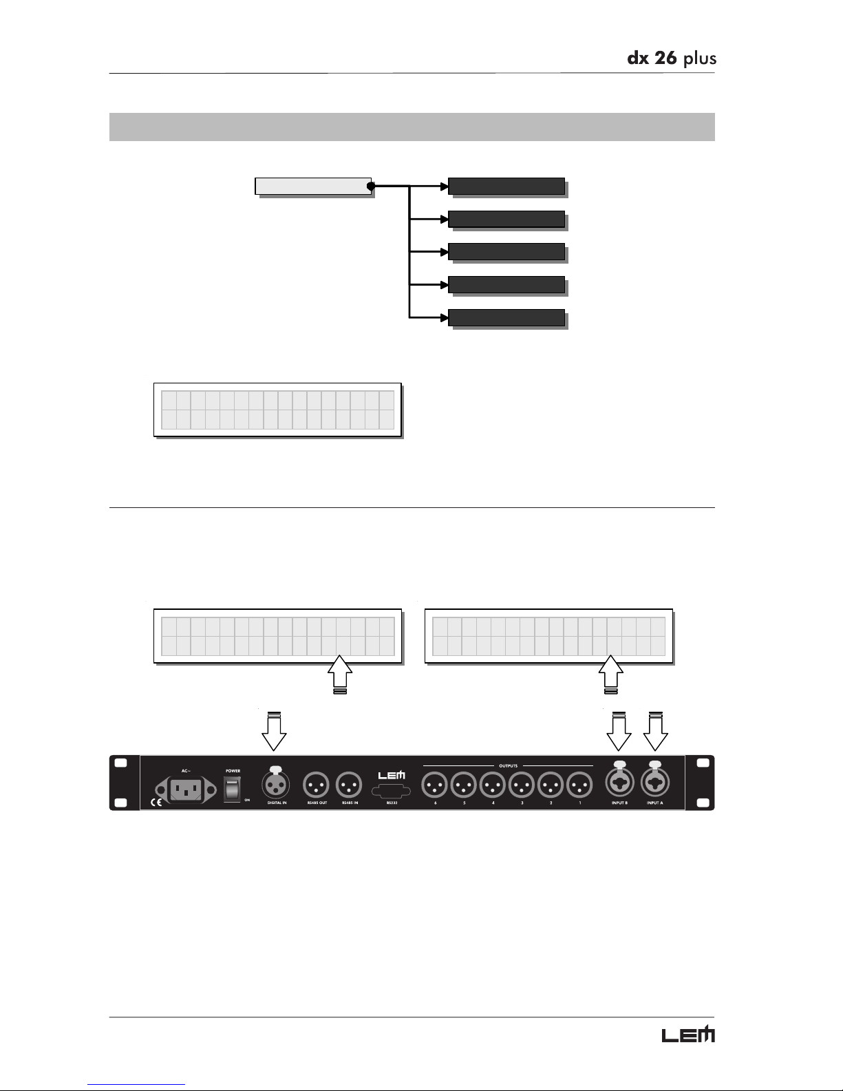
Allows to choose which DX 26 PLUS inputs to use.
The options include:
Digital Inputs Analog Inputs
Input Select
Analo
g
Input Select
Di
g
ital
The inputs selected become Input A and Input B.
Any signal on the inputs not selected is ignored.
UTILITY menu
Page 45
45
Output Meters
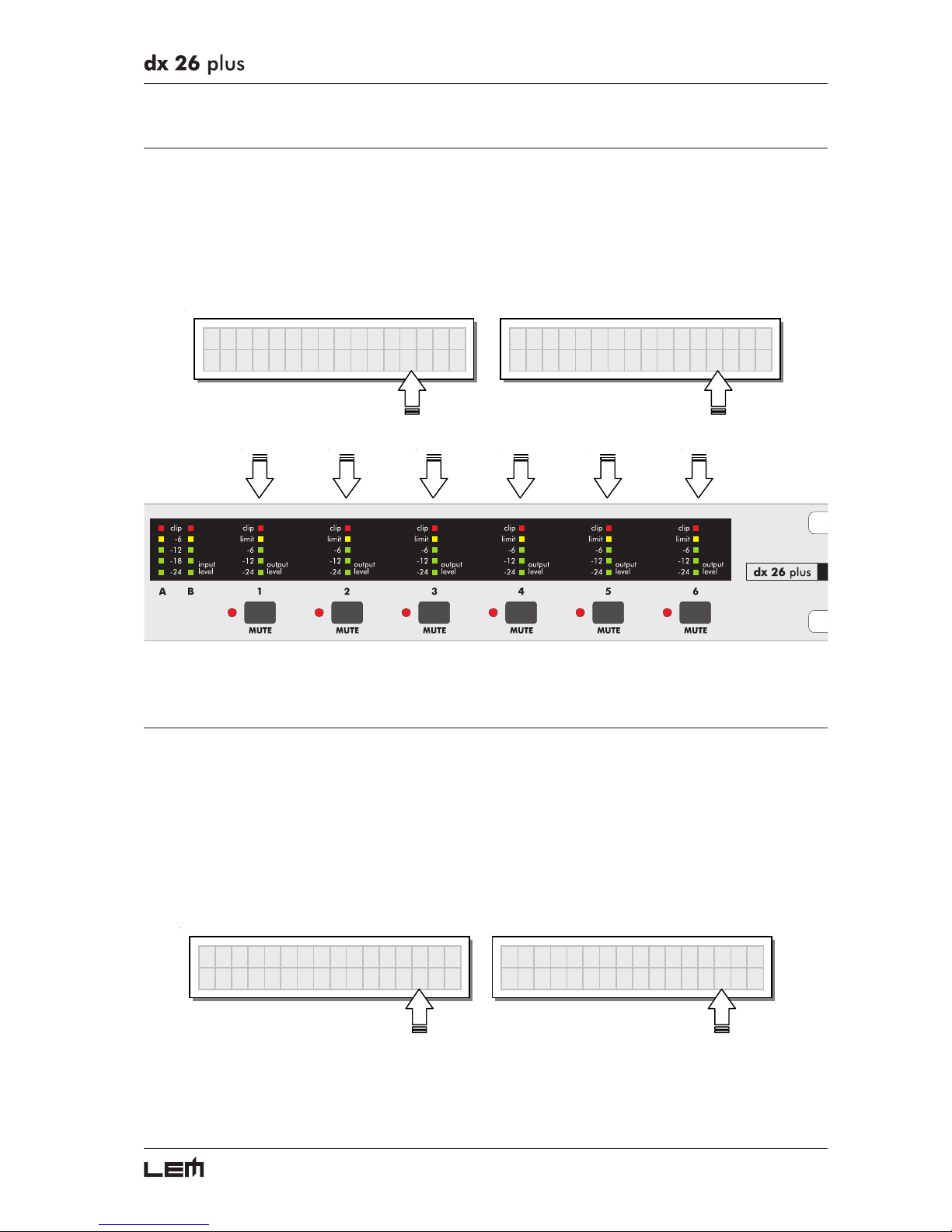
Allows to decide whether to display the outputs’ signal before or after MUTE.
The options include:
PreMute PostMute
the signal is always shown the signal is only shown if
no matter what the MUTE status the output isn’t in MUTE
Output Meters
PreMute
Output Meters
PostMute
Temperature
Allows to key in the value of the environmental temperature of place of installation.
The system uses this value to automatically compensate for the differentials due to the difference
speed of sound transmission according to the air temperature.
This allows to set the delays during the sound-check and only have to reset them automatically
when necessary (for example during a concert, in the event of big jumps in temperature, etc.).
The editing values are in the following ranges: +60°C ÷ -30°C with 1°C steps
140.0°F ÷ -22.0°F with 1.8°F steps
Temperature
20°C
Temperature
68.0°F
N.B.: the measurement units can be chosen between °C (degrees Centigrade) and °F (degrees Fahrenheit) by means
of the Temperature Unit function (UTILITY menu - Units submenu).
UTILITY menu
Page 46
46
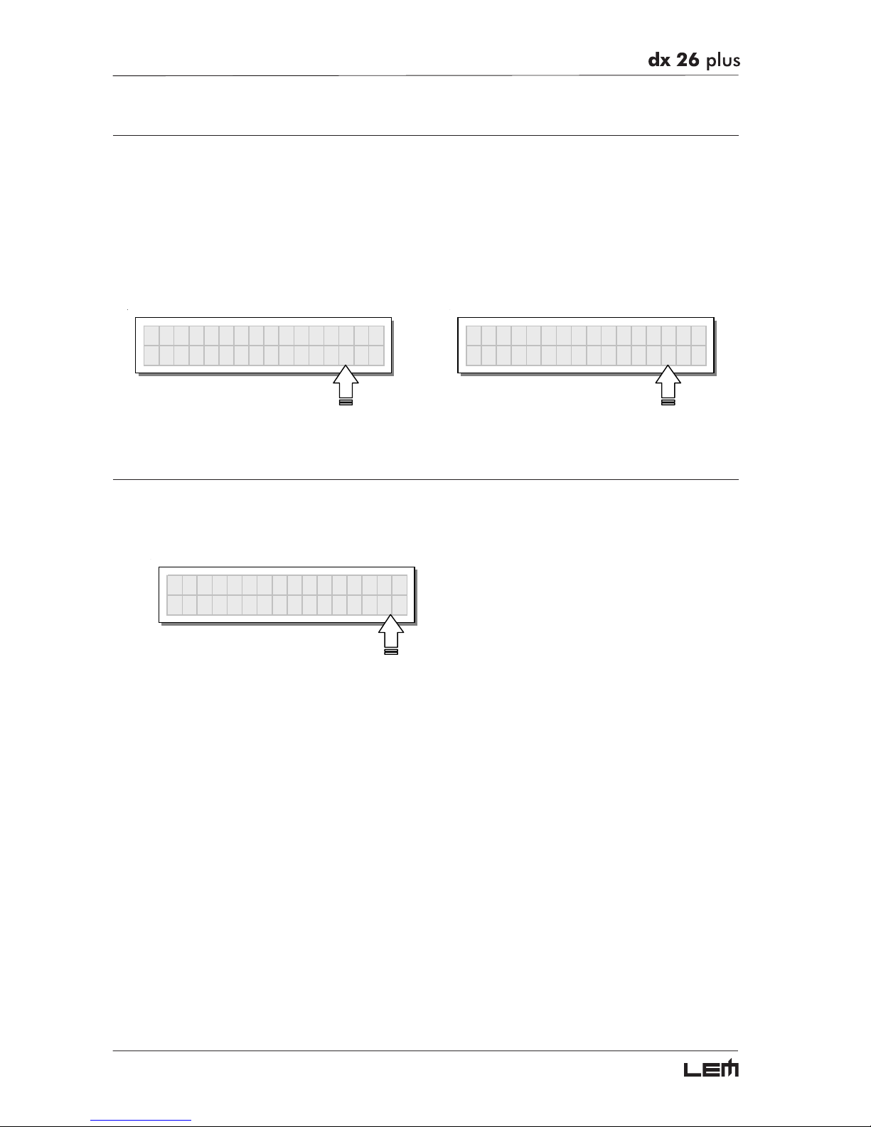
Wake Up
Allows to choose the mode in which MUTE functions are restored when the DX 26 PLUS is
switched on.
The options include:
Normal Mute
when switched on, the system restores the last when switched on, the system automatically
MUTE configuration before switching off sets all the outputs in MUTE
Wake U
p
Normal
Wake U
p
Mute
LCD Contrast
Allows to adjust the Display contrast.
The values are in the following range: 0 (minimum contrast) ÷ 32 (maximum contrast).
LCD Contrast
26
UTILITY menu
Page 47
47
LOCK SUBMENU
Lock Lock
Allows to enable or disable the protection of the system against accidental or unauthorized changes.
Lock
This function is very useful whenever even temporary changes or tampering with the settings stored in
the system must be prevented. For example: fixed installations used by several operators (discotheques,
clubs, conference halls, etc.), sound system rental, etc.
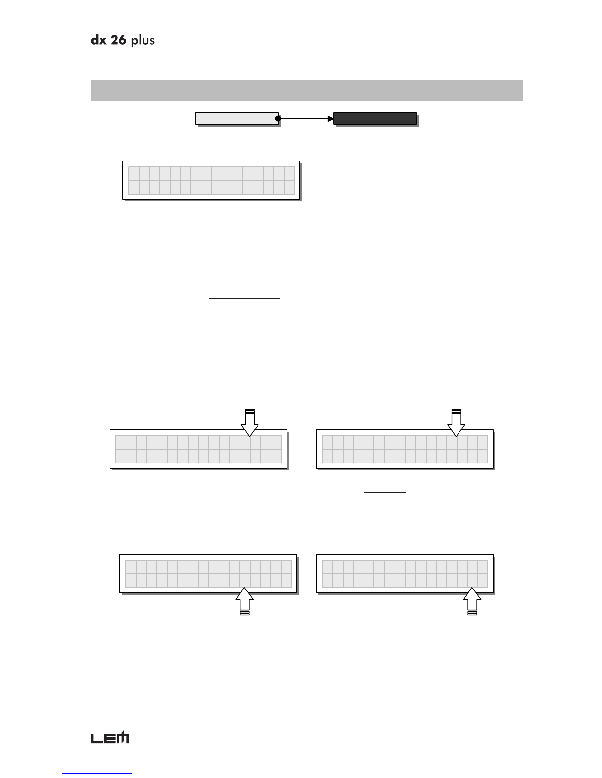
How to enable protection
☞
First of all, choose the protection mode:
Two modes are available:
Total: Partial:
all editing functions are blocked and only the parameters relative to the Inputs
access to the PRESET menu is disabled can be edited (Delay, Gain, EQ),
all other editing functions are blocked
and access to the PRESET menu disabled
LOC
K
Total
Password
[
NIC
K
]
LOC
K
Partial
Password
[
NIC
K
]
☞
Then use the and keys to access the area in which the password is entered.
I
MPORTANT! The protection cannot be unlocked without the password!
So write it down or at least choose a word that is easily remembered.
The password is made up of four alphanumerical characters, obtainable using the
and keys and
editable with the DIAL
LOC
K
Partial
Password
[
NIC
K
]
LOC
K
Partial
Password
[
WOLF
]
☞
After entering the password, press ENTER.
N.B.: confirmation is only accepted if the cursor is positioned on one of the password’s four characters. This allows to
avoid accidental enabling, without having seen the password.
Protection is enabled and the system takes up default status.
UTILITY menu
Page 48
48
How to disable the protection
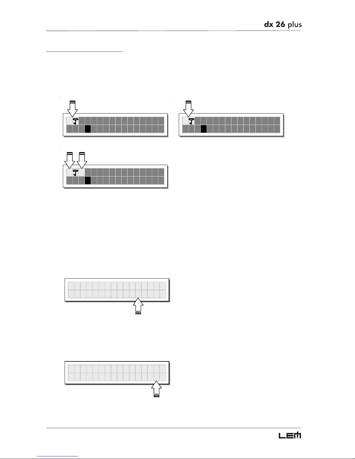
If the protection is enabled, when the system is in default status (i.e. when none menu LEDs are lit and
therefore no type of editing is enabled), the following appears on the display:
Total Protection enabled Partial Protection enabled
T A13 B24 S56
2U 2x2W+2MAX
P A13 B24 S56
2U 2x2W+2MAX
TMA13B24S56
2U 2x2W+2MAX
N.B.: alongside the symbol of Total or Partial protection, the letter M may also appear. This means that the system is
protected, but the PRESET in question has undergone one or more changes that have not yet been stored. You can
however switch the system on and off without any problems, as the current settings are kept in the buffer memory.
Nevertheless, if this is your work setup, it’s advisable to store it in a PRESET.
To unlock the protection:
☞
Access the LOCK submenu.
The display shows the prompt for entering the password to unlock the protection.
The four alphanumeric characters of the password are encrypted.
UNLOC
K
Password
[
****
]
☞
Enter in the password using the combination of the and keys and the DIAL,
then press ENTER.
NB: in the event of an incorrect password, the display prompts again, encrypting all the characters again.
UNLOC
K
Password
[
WOLF
]
Protection is unlocked and the system enters default status.
UTILITY menu
Page 49
49
MEMORY CARD SUBMENU
Memory Card Format Card
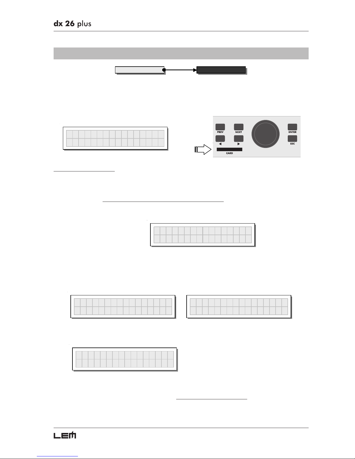
Allows to format the Multimedia Memory Card.
Formatting is the preparation of the memory areas of the Card. Without formatting (or without compatible
formatting) the Card can’t be used by the system.
Memor
y
Card
How to format the Card
☞
Insert a Multimedia Memory Card in the slot.
New or used Cards can be used, providing they are compatible (min 1MB).
ATTENTION! Formatting cancels any data contained in the Card.
☞
In the Memory Card submenu, press ENTER.
The Format Card page appears.
Format Card
☞
Press ENTER.
The system formats the Card until it communicates that it has completed.
This operation only requires a few seconds. The Card is ready to be used.
Format Card
Formattin
g
...
Format Card
Format Done !
N.B.: in the event of an error or a Card fault, if there is no Card in the slot or if the Card is removed during formatting,
the display shows the following message:
Format Card
Format Error !
During formatting, the system automatically stores the *Default* PRESET in all the 128 CARD memory
areas.
N.B.: since the system must always be configured, there are no empty memory areas. All the User and Card areas
not yet used by stored user data are automatically occupied by the *Default* PRESET, which contains a standard
start
configuration with all the values of the various parameters at zero.
UTILITY menu
Page 50
50
COMM. SETUP SUBMENU
Comm. S e tup Preset Change RX
This submenu allows access to the setting of communication with other units via the serial ports.
N.B.: the Dump Out PRESET and Incoming Dump functions are an exception, as they’re controlled directly in the
PRESET menu.
Comm. Setu
p
PRESET Change RX
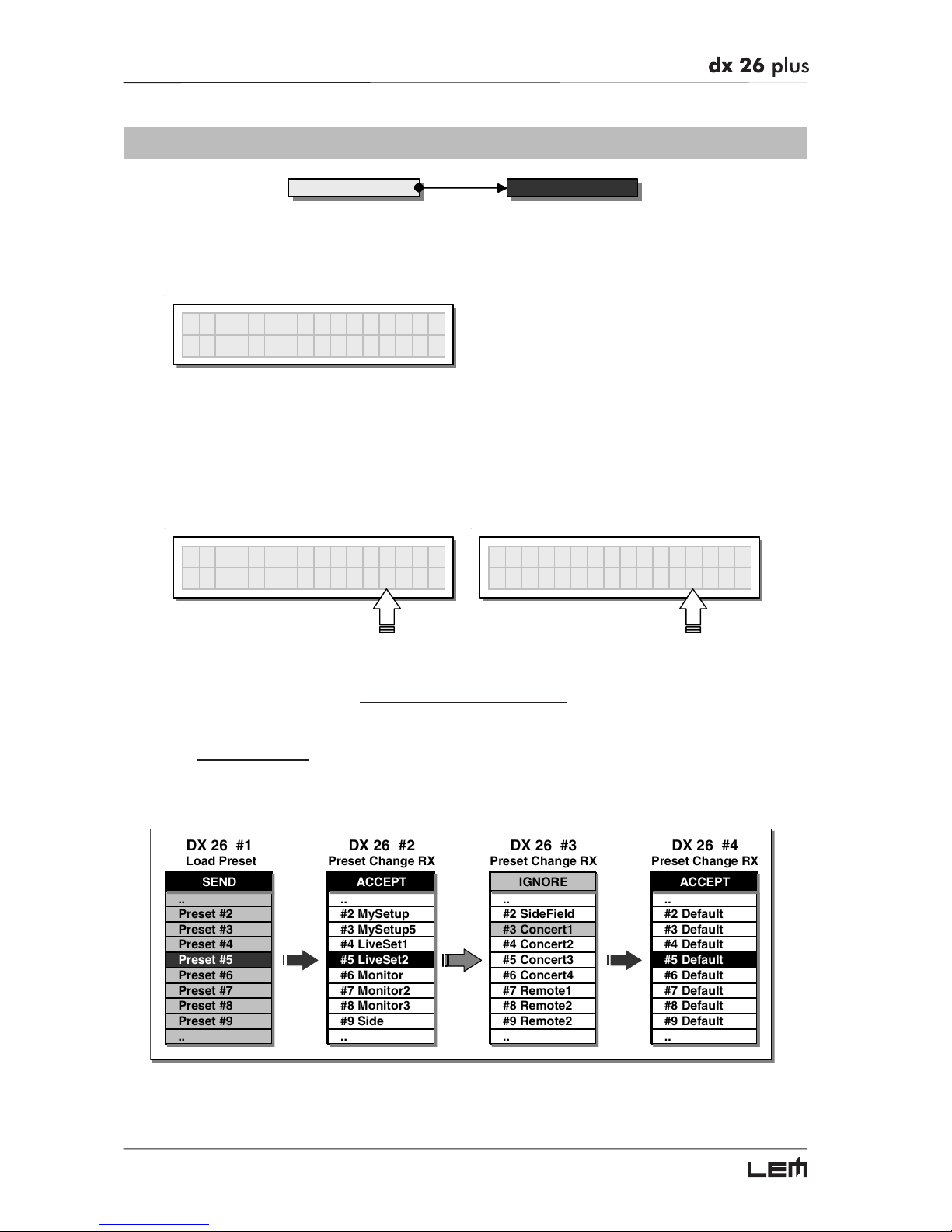
Allows to accept or ignore the PRESET Change command sent via the serial ports from a computer
or another DX 26 PLUS when it loads a PRESET.
The settings can be:
Ignore PRESET Change commands received.Accept and execute PRESET Change commands.
Preset ChangeRX
Acce
p
t
Preset ChangeRX
I
g
nore
The PRESET Change command is completely identical to MIDI Program Change: the transmitting
unit sends an instruction containing a number of PRESETS to load; the receiving units (if they are
able to accept the command) each loads into its own memory the PRESET with the corresponding
number.
This means that, in a chain of DX 26 PLUS, all the units set with “PRESET Change RX = Accept”
load the same number of PRESET, in spite of the fact that it corresponds to PRESETS with different
contents in the various units.
N.B.: to transmit the same contents, the PRESET Dump function is used.
DX 26 #1 DX 26 #2 DX 26 #3 DX 26 #4
Load Preset Preset Change RX Preset Change RX Preset Change RX
SEND ACCEPT IGNORE AC CEPT
.. .. .. ..
Preset #2 #2 MySetup #2 SideField #2 Default
Preset #3 #3 MySetup5 #3 Concert1 #3 Default
Preset #4 #4 LiveSet1 #4 Concert2 #4 Default
Preset #5 #5 LiveSet2 #5 Concert3 #5 Default
Preset #6 #6 Monitor #6 Concert4 #6 Default
Preset #7 #7 Monitor2 #7 Remote1 #7 Default
Preset #8 #8 Monitor3 #8 Remote2 #8 Default
Preset #9 #9 Side #9 Remote2 #9 Default
.. .. .. ..
SERIAL PORT
SERIAL PORT
SERIAL PORT
UTILITY menu
Page 51
51
Configurations
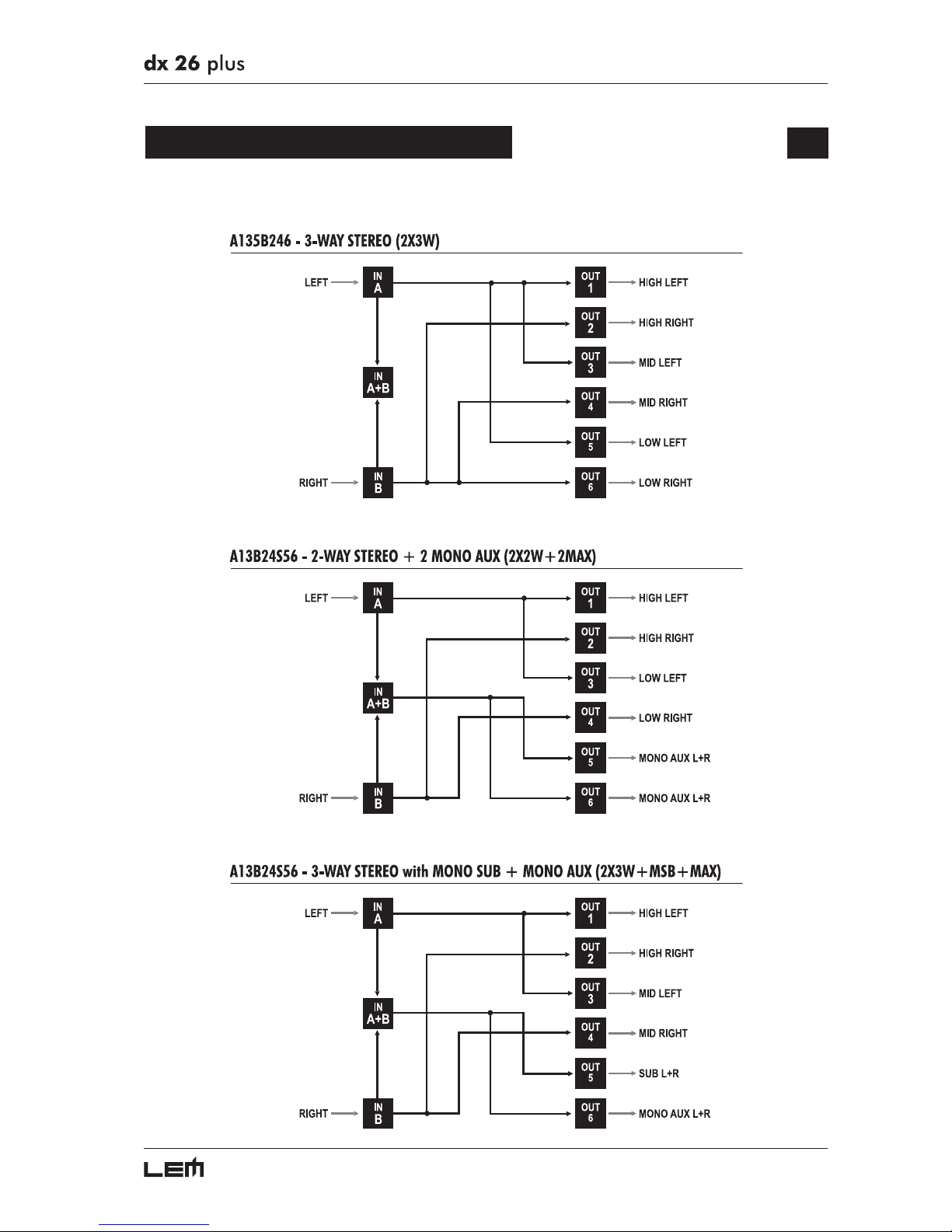
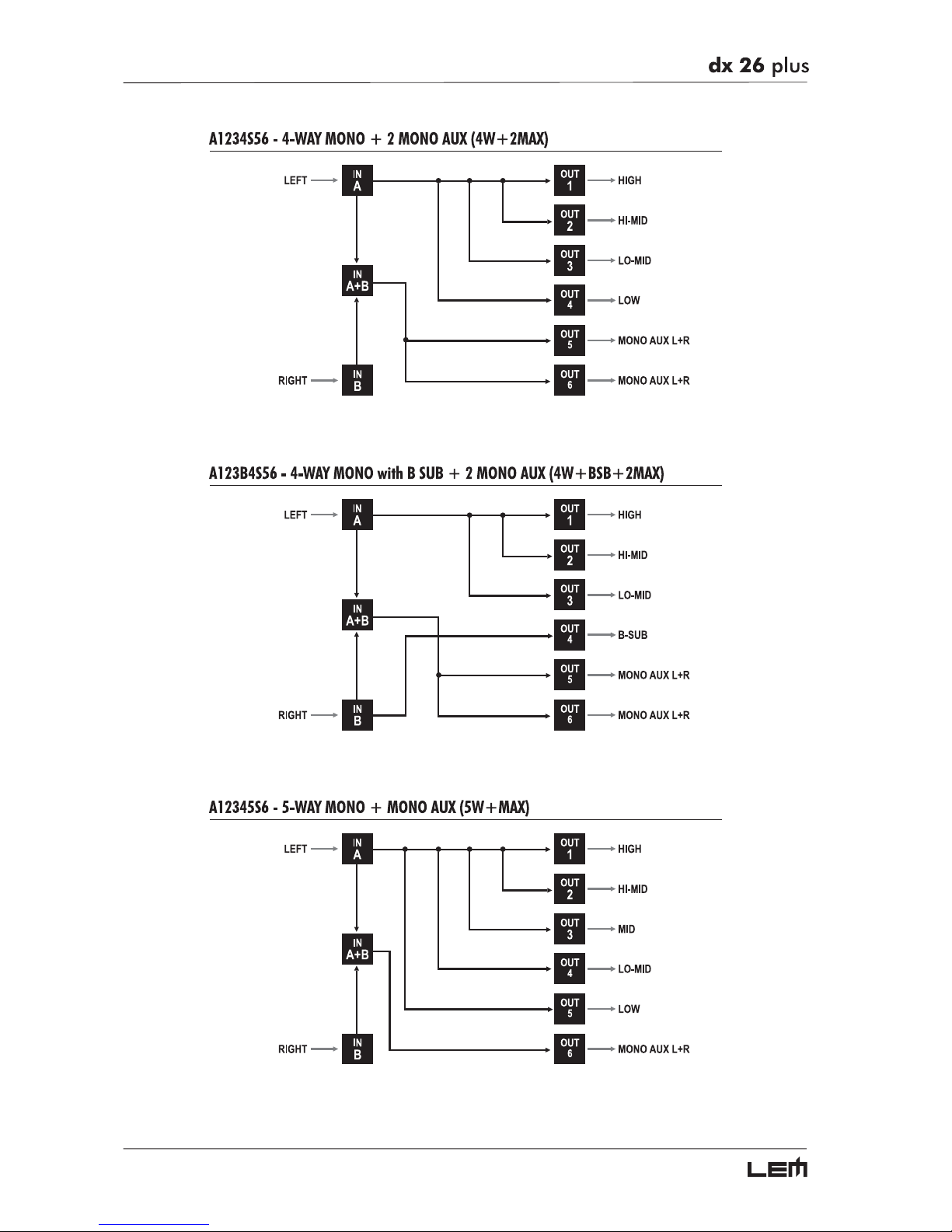
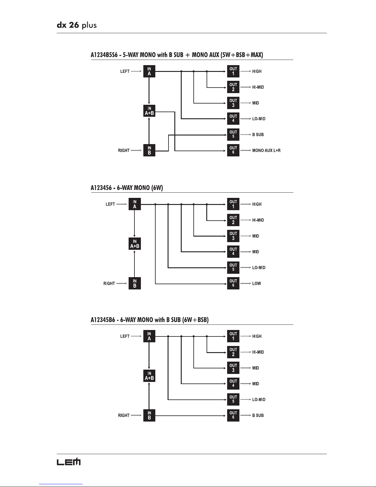
The following diagrams show the DX 26’s various system configurations, as if to say the various input
and output hardware combinations.
Configurations
Page 52
52
Configurations
Page 53
53
Configurations
Page 54
54
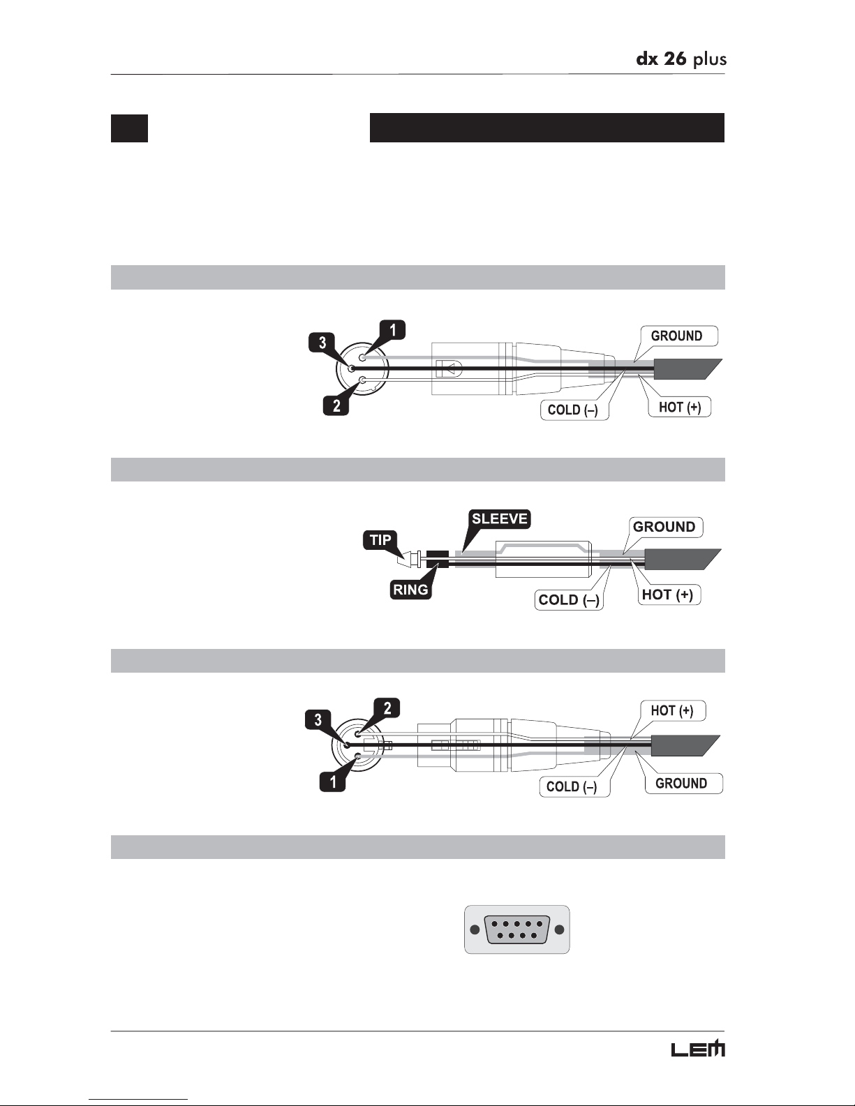
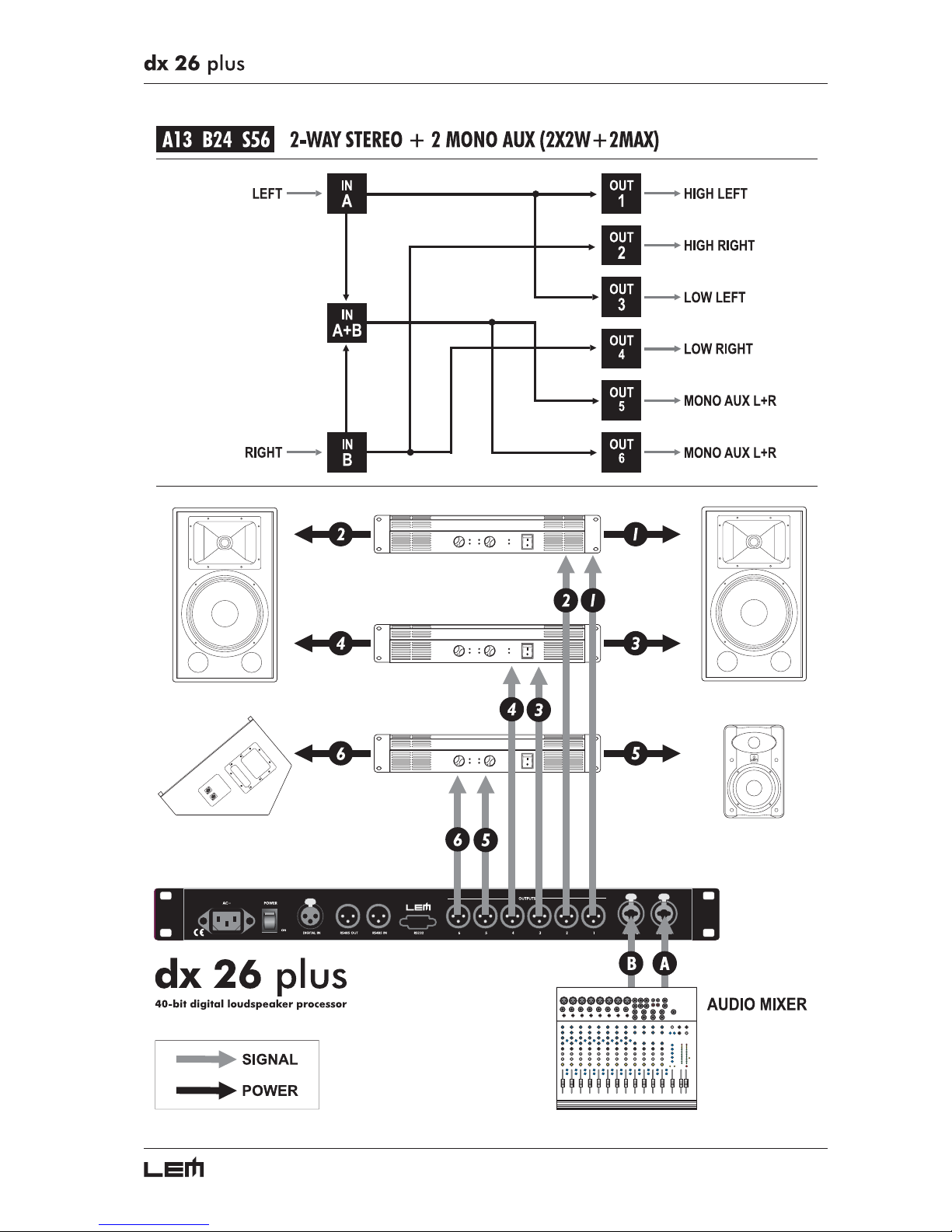
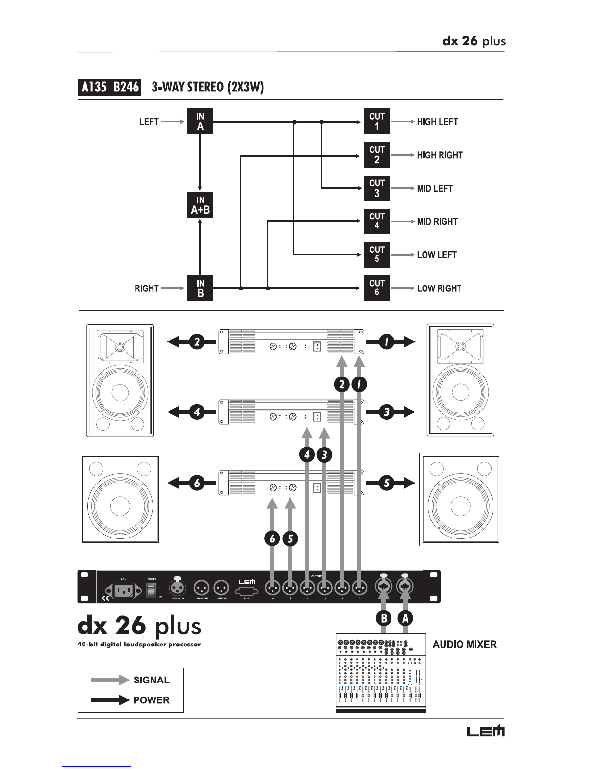
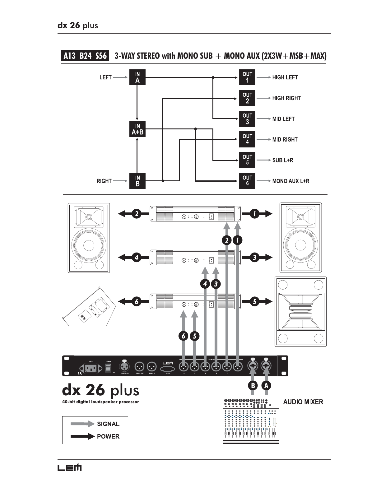
Connections
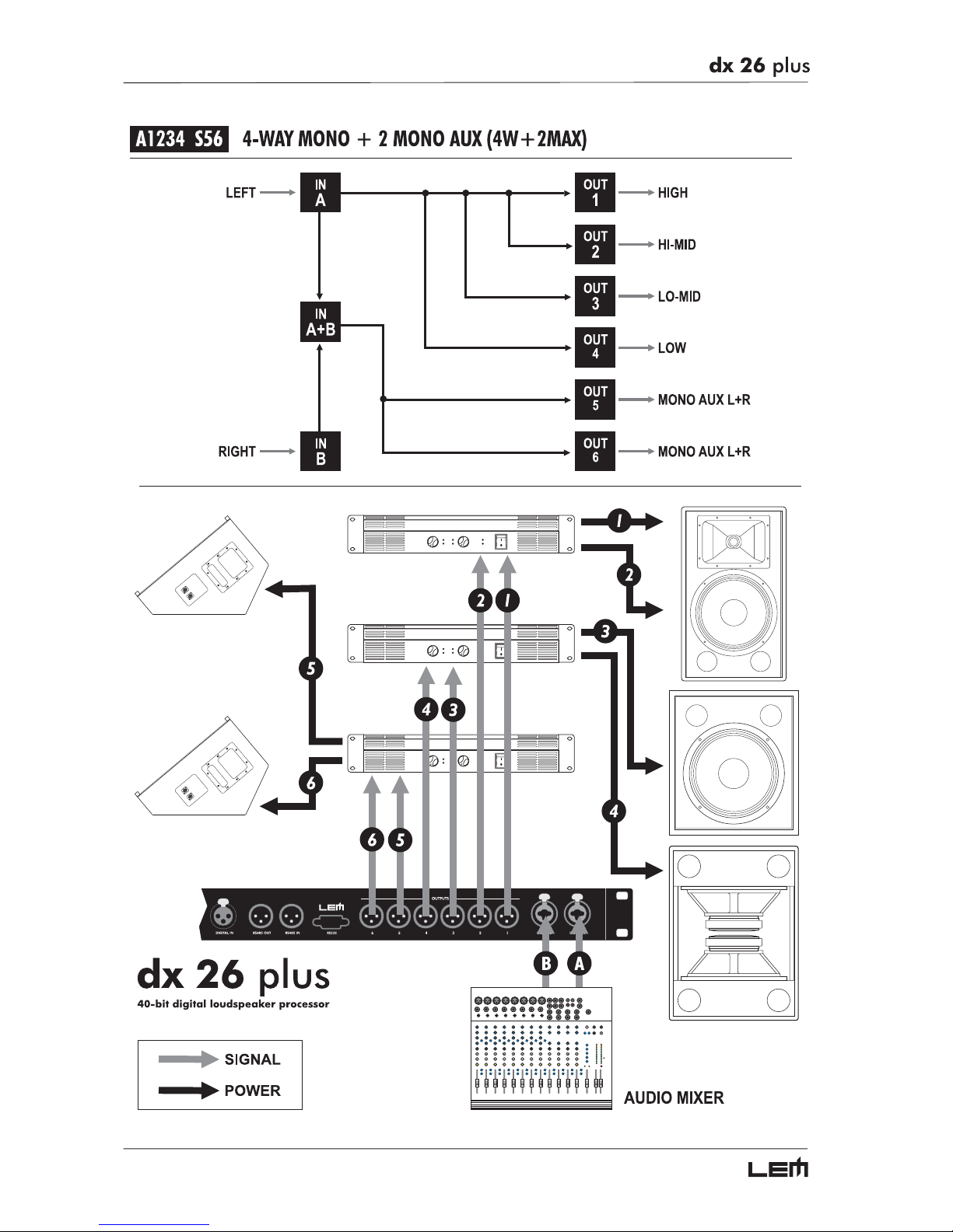
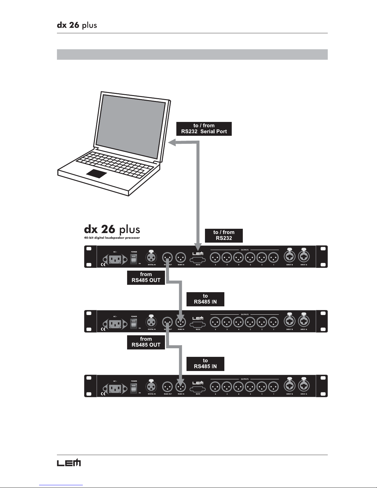
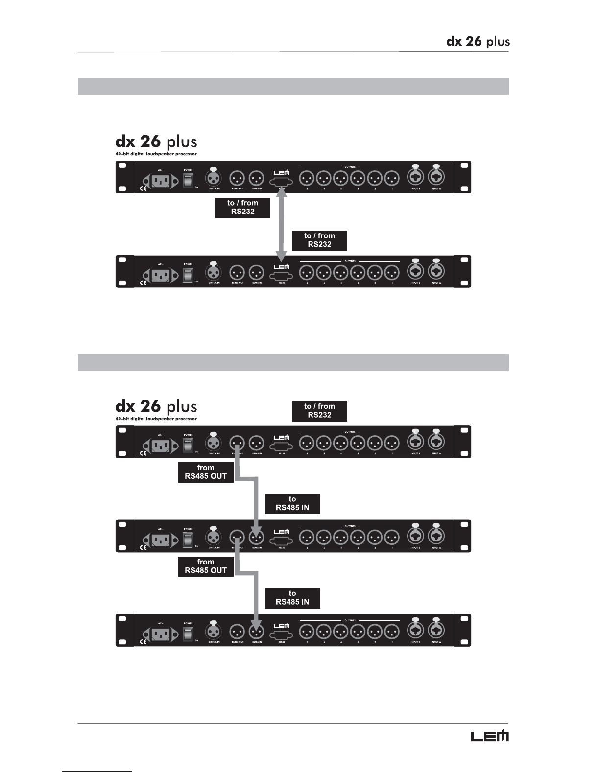
The following diagrams show the schemes of the recommended cables and some connection examples
referred to various system configurations.
Inputs A & B, Digital IN, RS485 IN
BALANCED XLR-M
Inputs A & B
BALANCED JACK
Outputs 1÷6, RS485 OUT
BALANCED XLR-F
RS232
RS232 (9-Pin)
Connections
Page 55
55
Connections
Page 56
56
Connections
Page 57
57
Connections
Page 58
58
Connections
Page 59
59
Communications: PC & one or more DX 26 PLUS connection
Connections
Page 60
60
Communications: two DX 26 PLUS short distance connection
Communications: two or more DX 26 PLUS long distance connection
Connections
Page 61
61
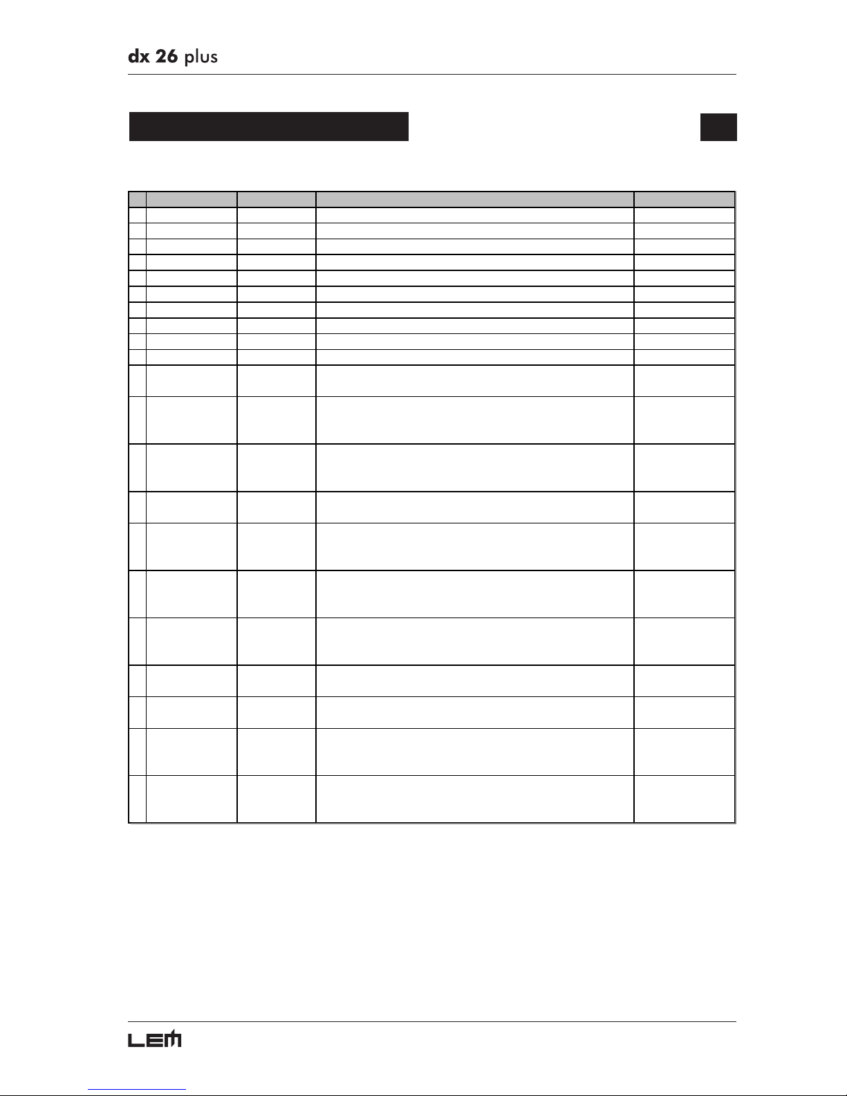
Factory PRESETS
# Name Configuration Description Amplifiers
01 DEFAULT A135 B246 Default preset - routing = 3-WAY STEREO -
02 2X2W+MAX A13 B24 S56 2-WAY STEREO + 2 MONO FULL-RANGE OUT 03 2X3W A135 B246 3-WAY STEREO 04 2X3W+MSB+MAX A13 B24 S56 3-WAY STEREO with MONO SUB + 1 MONO FULL-RANGE OUT -
05 4W+2MAX A1234 S56 4-WAY MONO + 2 MONO FULL-RANGE OUT 06 4W+BSB+2MAX A123 B4 S56 4-WAY MONO with B-SUB + 2 MONO FULL-RANGE OUT 07 5W+MAX A12345 S6 5-WAY MONO + 1 MONO FULL-RANGE OUT 08 5W+BSB+MAX A1234 B5 S6 5-WAY MONO with B-SUB + 1 MONO FULL-RANGE OUT 09 6W A123456 6-WAY MONO 10 6W+BS B A12345 B6 6-WAY MONO with B-SUB -
11 K6 A13 B24 S56 1 x K6 (for each side)
PFC3 (75W/8ohm)
PFC5 (500W/8ohm)
12 K6+KL A135 B246 1 x K6 + 1 x KL (for each side)
PFC3 (75W/8ohm)
PFC5 (500W/8ohm)
PFC5 (600W/8ohm)
13 K6+2xKL A135 B246 1 x K6 + 2 x KL (for each side)
PFC3 (75W/8ohm)
PFC5 (500W/8ohm)
PFC5 (1200W/4ohm)
14 K3 A13 B24 S56 1 x K3 (for each side)
PFC3 (50W/8ohm)
PFC3 (300W/8ohm)
15 K3+KL A135 B246 1 x K3 + 1 x KL (for each side)
PFC3 (50W/8ohm)
PFC3 (300W/8ohm)
PFC5 (600W/8ohm)
16 TM18 PR A135 B246 1 x TM18.3 MH + 1 x TM18.3 L (for each side)
PFC3 (90W/8ohm)
PFC3 (250W/8ohm)
PFC5 (1500W/4ohm)
17 TM18 F L A135 B246 1 x TM18.3 MH + 1 x TM18.3 L (for each side)
PFC3 (90W/8ohm)
PFC3 (250W/8ohm)
PFC5 (1500W/4ohm)
18 TM15 PR A13 B24 S56 1 x TM 15.2 (for each side)
PFC3 (90W/8ohm)
PFC5 (800W/8ohm)
19 TM15 F L A13 B24 S56 1 x TM 15.2 (for each side)
PFC3 (90W/8ohm)
PFC5 (800W/8ohm)
20 TM15+18 PR A135 B246 2 x TM15.2 + 1 x TM18.3 L (for each side)
PFC3 (180W/4ohm)
PFC3 (1500W/4ohm)
PFC5 (1500W/4ohm)
21 TM15+18 F L A135 B246 2 x TM15.2 + 1 x TM18.3 L (for each side)
PFC3 (180W/4ohm)
PFC3 (1500W/4ohm)
PFC5 (1500W/4ohm)
IMPORTANT NOTE
The OUTPUT LEVEL and LIMITER THRESHOLD settings of the FACTORY PRESETS for LEM
enclosures have been made considering the OUTPUT POWER and INPUT SENSITIVITY
specifications of the LEM POWERFACTOR amplifiers in the CONSTANT GAIN (26dB) configuration.
Therefore, if amplifiers with different specifications are used, these parameters need to be
consequently adjusted.
Factory PRESET
Page 62
62
Technical Specifications
Connectors 2 x COMBO
Nominal input sensitivity 0 dB (0.775 V)
Input Impedance 30kOhm, electronically balanced
Maximum Input Level +20dBu
Input Gain -30 / +6 dB variable in 0.5 dB steps
Digital input AES/EBU, XLR-F
Digital input sample rate 32 kHz ÷ 48 kHz
Connectors 6 x XLR-M
Output Impedance 600 Ohms, electronically balanced
Nominal Output Level 0 dBu
Maximum Output Level +20 dBu
Out put Gain -30 / +6 dB variable in 0.5 dB steps
A/D converters 24 bit
D/A converters 24 bit
Internal dynamics 40 bit
Sampling frequency 48 kHz
Configuration 2-WAY STEREO, 3-WAY STEREO, 2,3,4,5,6-WAY MONO
Crossover Filters Type Bessel, Butterworth or Linkwitz-Riley
Crossover Filters Slope 6, 12, 18, 24, or 48dB per octave
Delay Step 21 microseconds minimum
Max Delay time 2621 ms (inputs), 291 ms (outputs)
EQ filters Up to 40 maximum (depending on the crossover slope)
EQ Type Peak, 6dB Lo-Shelf, 12dB Lo-Shelf, 6dB Hi-Shelf, 12dB Lo-Shelf, Notch
EQ Gain +/15dB, variable in 0.5dB steps
EQ Bandwidth 0.05 to 3.00 octaves, variable in 0.05 steps
EQ freq 15.6 Hz to 16 kHz
Dynamics Compressor/Limiter on the outputs - Noise Gate on the inputs
Memories 21 FACTORY PRESETS + 64 USER PRESETS + 128 CARD PRESETS
Communications 9-pin RS232, XLR-F RS485 IN, XLR-F RS485 IN
Frequency Response 20Hz - 20kHz, ±0.25dB
Dynamic range
>117dB 20Hz to 20kHz
>120dB 20Hz to 20kHz on AES/EBU input
Channel Separation >100dB 20Hz to 20kHz
Distortion (THD) 0.05% , 20Hz to 20kHz
Input Metering -24dB, -18dB, -12dB, -6dB, CLIP relative to Clip point (+20dBu)
Output Metering -24dB, -12dB, -6dB, LIMIT relative to limiter threshold setting, CLIP
Dimensions 483x44x300 mm
Weight 4.0 Kg
Power supply see label on the unit
General
DSP Section
INPUT section
Output Section
Features
General Performance (with filters out)
Technical Specifications
Page 63

FEDERAL COMMUNICATIONS COMMISSION
NOTE: This equipment has been tested and found to comply with the limits for a Class A
digital device, pursuant to Part 15 of FCC Rules. These limits are designed to provide
reasonable protection against harmful interference when the equipment is operated in a
commercial environment. This equipment generates, uses and can radiate radio frequency
energy and, if not installed and used in accordance with the instruction manual, may cause
harmful interference in which case the user will be required to correct the interference at his
own expense.
CAUTION: Changes or modifications to this product not expressly approved by the
manufacturer could void the user’s authority to operate this product.
Le informazioni contenute in questo documento sono state attentamente redatte e controllate. Tuttavia
non è assunta alcuna responsabilità per eventuali inesatezze.
Tutti i diritti sono riservati e in questo documento non può essere copiato, fotocopiato, riprodotto per
intero o in parte senza previo consenso scritto della GENERALMUSIC S.p.A.
GENERALMUSIC si riserva il diritto di apportare senza preavviso cambiamenti e modifiche estetiche,
funzionali o di design a ciascun proprio prodotto.
GENERALMUSIC non assume alcuna responsabilità sull’uso o sull’applicazione dei prodotti o dei circuiti
qui descritti.
STAMPATO IN ITALIA
The information contained in this publication has been carefully prepared and checked. However no
responsibility will be taken for any errors.
All rights are reserved and this document cannot be copied, photocopied or reproducted in part or
completely without written consent being obtained in advance from GENERALMUSIC S.p.A.
GENERALMUSIC reserves the right to make any aesthetic, functional or design modification to any of its
products without prior notice.
GENERALMUSIC assumes no responsibility for the use or aoolication of the products or circuits
described herein.
PRINTED IN ITALY
Page 64

 Loading...