

Page 1
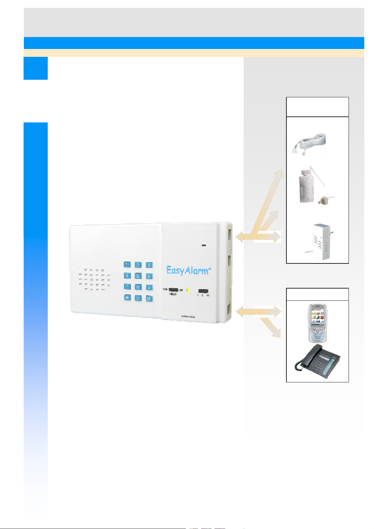
Alarm
LEITRONIC AG
Wired
s
ensors
Swiss Security Systems
TELE-ALARM / TELE-CONTROL
User instructions
EasyAlarm BASIC®/ COMBI
®
Sensor-connection
cord
Motion sensor
Siren-/Switch
module
5. October 2010
Issue No.: 8.38
EA8-BASIC-COMBI-8-38-GB.DOC
Page 2

Table of contents
1. Introduction.............................................................................................................................................................3
2. Safety instructions...................................................................................................................................................4
2.1 Approval........................................................................................................................................................................... 4
2.2 Telephone connection........................................................................................................................................................ 4
2.3 Power supply..................................................................................................................................................................... 4
2.4 Safety notes....................................................................................................................................................................... 4
3. Set view / Function elements ..................................................................................................................................5
4. Setup........................................................................................................................................................................6
4.1 Operation with Plug&Protect motion sensor (EasyAlarm COMBI)...................................................................................... 6
4.2 Operation with potential free alarm contacts (EasyAlarm BASIC)....................................................................................... 8
5. Configuration of the alarm registers......................................................................................................................10
5.1 Sensor-1 monitoring......................................................................................................................................................... 10
5.2 Sensor-2 monitoring......................................................................................................................................................... 11
5.3 Sensor-3 monitoring......................................................................................................................................................... 12
5.4 Acoustical monitoring...................................................................................................................................................... 12
6. Programming.........................................................................................................................................................13
6.1 How to program new calling numbers............................................................................................................................... 13
6.2 Designation of thecalling number sequence...................................................................................................................... 14
6.3 How to select user language / How to record individual message....................................................................................... 14
6.4 How to program PIN-Code............................................................................................................................................... 15
7. Operation...............................................................................................................................................................16
7.1 Self check at power on..................................................................................................................................................... 16
7.2 Arm / Disarm system ....................................................................................................................................................... 16
7.3 Inactive waiting period..................................................................................................................................................... 16
7.4 Supervision mode ............................................................................................................................................................ 17
7.5 Alarm.............................................................................................................................................................................. 17
7.6 Alarm delay / Pre warning period / Entry delay................................................................................................................. 17
7.7 Phone connection............................................................................................................................................................. 18
7.8 Alarm repetition............................................................................................................................................................... 18
7.9 Test call........................................................................................................................................................................... 19
7.10 Dialling-in (check call)..................................................................................................................................................... 19
7.11 Answering an incoming call ............................................................................................................................................. 19
8. Useful Notes..........................................................................................................................................................20
8.1 Tone-dialling command................................................................................................................................................... 20
8.2 User information.............................................................................................................................................................. 20
8.3 Functional checks ............................................................................................................................................................ 21
8.4 Battery check / replacement.............................................................................................................................................. 21
8.5 Maintenance.................................................................................................................................................................... 21
9. Trouble Shooting / Error Handling .......................................................................................................................22
9.1 Telephone connection / Telephone communication........................................................................................................... 22
9.2 Motion detector usedas an alarm-sensor (sensor-1/2)........................................................................................................ 22
9.3 Sensor-1-contact.............................................................................................................................................................. 23
9.4 Sensor-2-contact.............................................................................................................................................................. 23
9.5 Sensor-3-contact.............................................................................................................................................................. 23
9.6 Acoustical monitoring...................................................................................................................................................... 23
10. Special programming............................................................................................................................................24
10.1 Factory settings (Default-Values)..................................................................................................................................... 24
10.2 Alarm repetition............................................................................................................................................................... 24
10.3 Entry / Exit period............................................................................................................................................................ 24
10.4 Mains power losstimeout................................................................................................................................................. 24
10.5 Signalling........................................................................................................................................................................ 24
10.6 Shared line with telephone/modem................................................................................................................................... 25
10.7 Dialling-in (Remote-access)............................................................................................................................................. 26
10.8 Remote programming....................................................................................................................................................... 26
11. Accessories............................................................................................................................................................28
11.1 Motion / Presence detector-PIR-RJ45 (Plug&Protect)....................................................................................................... 28
11.2 Siren EA-SIR-RJ45.......................................................................................................................................................... 29
11.3 230V-Switch EA-SWI ..................................................................................................................................................... 29
11.4 DIN-Adapter interface EA-ACDC-SWI-RJ45-RJ12.......................................................................................................... 29
12. Specifications / warranty.......................................................................................................................................30
12.1 Specifications.................................................................................................................................................................. 30
12.2 AC-adapter BBT-DC12S-RJ45......................................................................................................................................... 30
12.3 Warranty......................................................................................................................................................................... 30
13. Index......................................................................................................................................................................31
14. Overview...............................................................................................................................................................32
2
Page 3

1. INTRODUCTION
EasyAlarm
most important functions are listed below. Please read the instruction manual carefully before you start installation.
Especially pay attention to the safetynotes.
®
is an easy to use and reliable auto-dialler including announcement unit that can be used in many ways. The
EasyAlarm is a reliable monitor
Cause of alarm Notes
Noise* Sensitivity I / II / III (LOW / MED / HIGH)
Keystroke Check call / emergency call
Wired sensor input 1*+ Potential separated sensor contact (NO/NC configurable)
=> possibility to trigger an alarm, if an expected repeated action fails
Wired sensor input 2*+ Potential separated sensor contact (NO/NC configurable)
Wired sensor input 3* Potential separated sensor contact (NO/NC configurable)
Technical states / condition
*Alarm delayselectable
+ individual announcement or a single stroke bell can be activated
Failure of main supply
Battery condition
EasyAlarm calls automatically
Destination Notes
Telephone / mobile phone Connection states Listing in: changeover to hands free on demand
Alarm withhands free connection
Pager Numeric alarm message
Alarm centre With protocol Point ID/Contact ID
Alarms up to nine pre programmed phone numbers
EasyAlarm indicates
Indication Notes
Individual announcement Up to 12 seconds duration, at the beginning of connection
Cause ofalarm Cause ofalarm (periodical announcement)
State of sensor
Technical state / condition Battery condition
EasyAlarm puts you in contact
Mode of contact Notes
Listening in During connection you can listen into the monitored room
Speaking You can talk to a person any time bychanging to hands free mode
EasyAlarm provides security
Security steps Notes
Alarm acknowledgement Without acknowledgement you can program up to nine alarm repetitions
Alarm forwarding Without acknowledgement an alarm will be forwarded to next programmed
number
Check call Remote access with PIN code (4 to 7 digits) at any time
EasyAlarm is a telecontrol system
Actions / Reactions Notes
Activation / deactivation ofsensors Wired alarm-sensors can be activated or deactivated at any time during
connection mode
Automatic activation of output By triggering ofan alarm an output (i.e. siren) can be switched on
automatically, or during connection mode using tone-dialling command
Remote activation of output In connection mode (tone-dialling command) the output can be switched to
drive for example a heater or air-condition unit
Remote programming: alarm number
and alarm-sequence
Alarm number and alarm-sequence can be changed during connection mode,
using tone-dialling commands
3
Page 4

2. SAFETY INSTRUCTIONS
2.1 Approval
Declaration of Conformity
According to the R&TTE Directive 1999/5/EC of 09.March 1999
Manufacturer’s Name: Leitronic AG
Manufacturer’s Address: Engeloostrasse 16
CH-5621 Zufikon, Switzerland
declares that the product
Product Name: EasyAlarm
Model Number: EA-8-EXT
conforms to the following product specifications:
Safety (R&TTE, Article 3.1a): EN60950: 1992+A1+A2+A3+A4
EMC (R&TTE, Article3.1b): EN 50081-1, 1992
EN 50082-1, 1997 Class B
Telephone: CTR21 asspecified in Council Decision 98/482/EC
Supplementary Information
The product herewith complies with the requirements ofthe following Directives and carries the CE marking accordingly:
the EMC directive 89/336/EWG
the Low Voltage Directive 93/68/EEC
Zufikon, 1. April 2008 Silvan Tognella
2.2 Telephone connection
EasyAlarm® is designed to connect to an analogue telephone line.This connection should remain in service after a mains
power. These are:
analogue PSTN
analogue port of an ISDN terminal (ISDN-NThas to be reprogrammed for emergency operation at the ab-port)
analogue port of a private exchange using UPS (Uninterruptible power supply 1h buffering)
GSM Interface with approval, i.e. EA-GSM-Interface from Leitronic.
Not suitable:
Voip or cable modem, as in case of power loss it is not functional!
The voltage of the telephone network is defined in EN 41003. It is higher than 40 V and therefore please beware for
electrical hazard and disconnect
2.3 Power supply
A transformer according to the safety regulation EN60950 provides power supply. 9V battery is used as a back up in case
of power failure. It is located on the rear side oft the device.
2.4 Safety notes
Do not bring the device into contact with a liquid (water).
Do not open the device (exception: opening of battery compartment).
Replace the 9V-battery as soon as the announcement “battery error” is announced.
Please note:The telephone cord must be disconnected before openingthe battery compartment because
otherwise youcan get in contact with the telecommunication voltage!
Check alarm functions and start a test-call, before the system is put in service.
In case that EasyAlarm® is used to monitor children, the supervising person must be in a suitable distance to
take immediate care for the child. EasyAlarm® does not replace personal supervision!
The same applies to handicapped persons, EasyAlarm® is not a substitute of a personal care taker!
An alarm by telephone is only successful if the alarmed party takescare of thefollowing points:
Alarm must not be answered byan answering machine or equal equipment
Mobile phones can be out of range (e.g. underground car park, shieldedrooms, remote areas..)
Take care of the charging condition of the mobile phone
Loud noise can prevent you from hearing the ringer
All the electrical connections have to be potentialfree. Observe the regulation according to EN60950.
4
Page 5
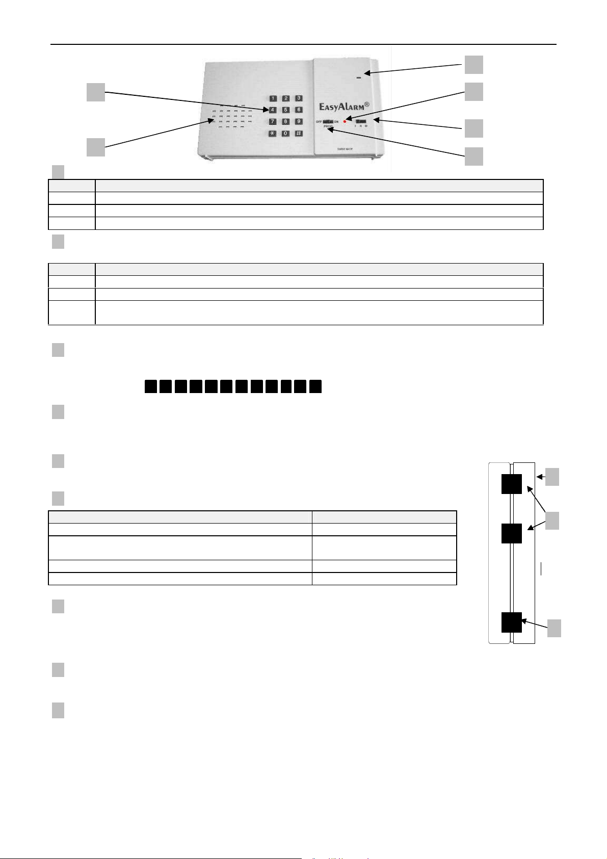
3. SET VIEW / FUNCTION ELEMENTS
798
5
3
4
6
2
1
1. Function switch
Position Information
OFF Device is switched off
PROG Entering of calling numbers, calling number sequence, PIN-Code and further parameters
ON Device is in supervision mode
2. Selection switch
EasyAlarm
Position Monitoring functions (Function switch on position ON)
I Wired sensor-1 enabled. Acoustical monitoring disabled!
II Wired sensor-1 enabled. Acoustical monitoring disabled!
III Wired sensor-1 enabled. Acoustical monitoring enabled with highest sensitivity => Alarm is triggered if
Note: Monitoring functions can be modified individuallyaccording to section 5.4ff!
®
monitors depending on the position of the selection switch
noise level is exceeded two or three times within a short period
3. Keypad
When function switch is on position PROG, you can enter the calling numbers or do further programming. If function
switch is on position ONpressing anykey will start a test call.
Keys are marked with 1 2 3 4 5 6 7 8 9 * 0 # .in the following sections.
4. Loudspeaker
The integrated loudspeaker is used for voice guidance during the programming as well as for hands-free communication
during phone connection.
5. Microphone
Is used during hands-free connection and for recording of individual message.
6. LED
Status of LED Operation mode
Green Waiting period
Green brief flashing every 4 seconds, also if acoustical
monitoring isactive byexceed set noise level
Green is on and offfor 4 seconds alternatively Supervision mode deactivated
Orange Phone connection
Supervision mode activated
7. Batterycompartment
The 9V-battery is used as a backup during power failure.
Please note:The telephone cord must be disconnected before openingthe battery
compartment because otherwise you can getin contact with the telecommunication voltage!
~
EXT/
-LINE
8. Telephone jack (-LINE)
The plug must be locked in the jack. To disconnect press pawl.
9. External ports (EXT/≂) for accessories (as motion sensor) and power supply.
5
Page 6
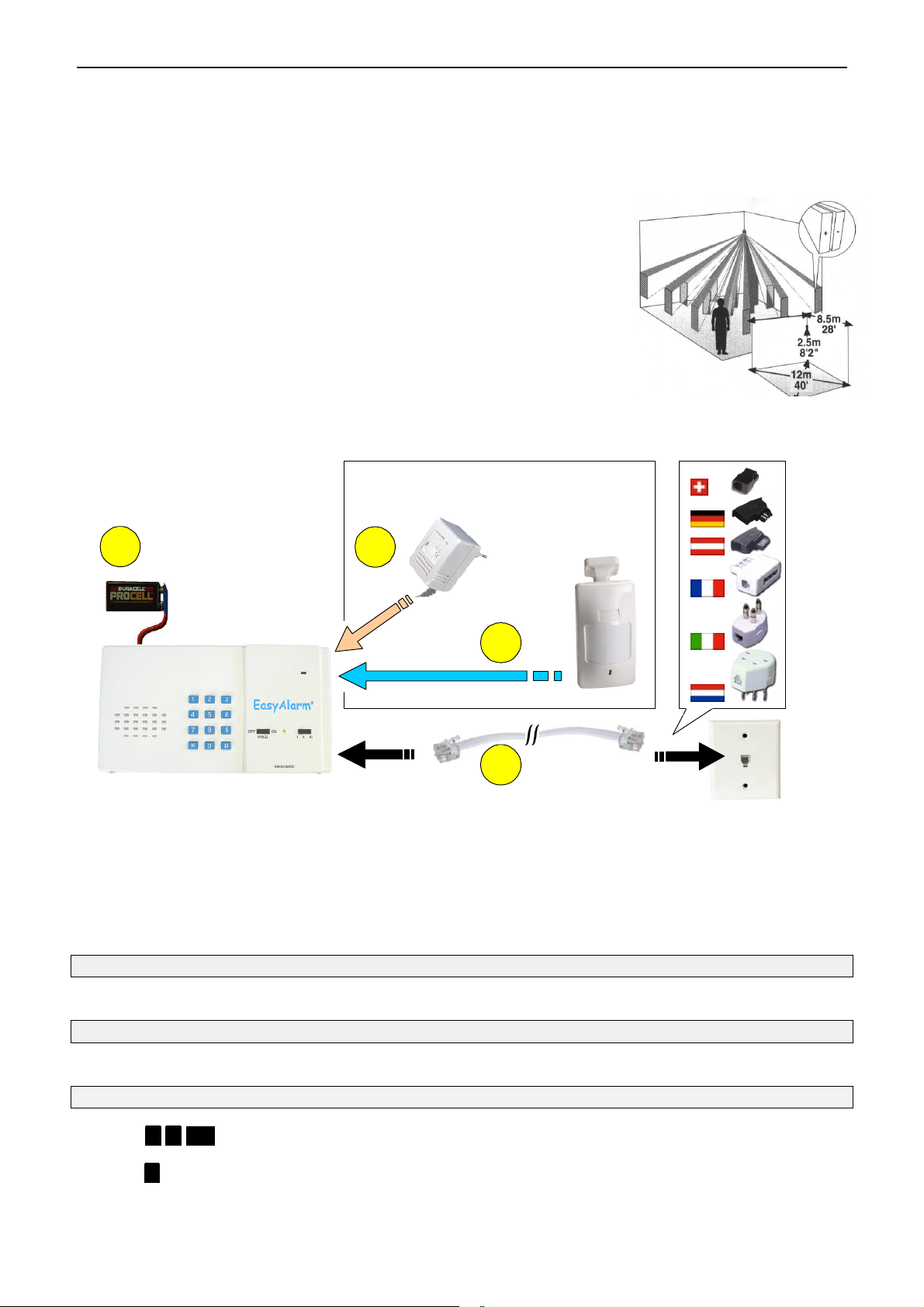
4. SETUP
214
3
4.1 Operation with Plug&Protect motion sensor (EasyAlarm COMBI)
4.1.1 Safety instructions
Function switch must be shifted to OFF and telephone-cord must be disconnected before anywiring work is
done on the AC-adapter or Motion sensor cable.
All the electrical connections have to be potentialfree. Observe the regulation according to EN60950.
All contacts have to be protected against any body contact
Do not plug the phone cable (5) into the EXT/≂-jack, only into -line jack of
alarm unit (1)!
4.1.2 Mounting PIR-motion sensor
Choose the mounting location after careful consideration of the area to be protected.
The motion detector should be located so that an intruder will cross the infrared beam
pattern. If used to verify presence, a regular used room should be detected. Figure
shows the different infrared beam patterns at a typical mounting height of 2.5m.
Notes:
Do not mount detector towards direct sunlight or near to heat sources.
Do not mount detector behind items like glass or curtains because the infrared-
beam cannot penetrate them.
Keep away pets like cats or dogs from the protected area.
Do not protect the same area by more then one detector, because they can interfere.
4.1.3 Installation
1. Slide function switch to OFF
2. Insert 9V battery into compartment on rear side of alarm unit
Please note:The telephone cord must be disconnected before openingthe battery compartment because otherwise
you can get in contact with the telecommunication voltage!
3. Connect the AC-adapter cable into one of the EXT/≂-ports of the alarm unit
4. Mount the motion detector and connect the cable to the other EXT/≂-port of the alarm unit
6. Plug AC-adapter to main socket
Test and adjust motion detector Details accordingto section 4.1.6
WALK-Test: Wait at least two minutes after power-up for the motion detector to be stabilised. After this time, check the
entire area by observing the LED. Adjust swivel if necessary.
Telephone connection
7. Plug enclosed telephone-cord into -Line-Jack of alarm unit and connect it with the telephonenetwork
If you share line withmodem/telephone please proceed according to section 10.6
Program calling number(s) Details according to section 6.1
8. Slide function switch to PROG
9. Enter * * <n> (selected calling number: Standard n = 1..9)
Corresponding calling number will be announced, followed by message “to modify press star“
10. Press * and enter calling number
11. Slide function switch to OFF
6
Page 7
Select user language / record individual message Details accordingto section 6.3
12. Slide function switch to PROG
13. Enter *. *. #.
Current individual messagewill be announced followed by “to modify press * , to stoppress # “
14. Select language for user announcements: (facultative)
Press key 1 to 4 to select user languages: 1 for German, 2for French, 3 for English GB, 4 for Italian
15. Press * and start speaking
16. Press # to finishrecording, max. duration is 12 seconds
New individualmessage will be announced. You can repeatsteps 14 to16 until text is fine!
17. Slide function switch to OFF
Program PIN-code Details according to section 6.4
18. Slide function switch to PROG
19. Press key #.
You can prevent the alarm unitfrom unintended re-programming by pressing * ..
20. Enter PIN-code (4 to 7digits)
21. Press key #.
22. Re-enter PIN-code for confirmation
23. Press key #.
New PIN-code will be announced
24. Slide function switch to OFF
Alarm unit is now readyfor operation Details according tosection 7
25. Slide selection switch to the requested position (I/II/III)
4.1.4 Activation of motion sensor
Provided the motion detector is plugged in, EasyAlarm® detects the motion detector during the switching on procedure.
Important notes:
By disconnecting the motion detector during the operation mode, an alarm is
triggered followed by the announcement:”alarm due to sensor 1,sensor failure!”
By connecting the motion detector after the start up procedure of the alarmunit,
an alarmis triggered followed bythe announcement:“alarm due to sensor 1,
sensor 1 activated!”
4.1.5 Deactivation of motion sensor
If the motion detector is not plugged in, EasyAlarm® automatically deactivates the
supervision ofthe motion detector.
4.1.6 Adjustment
Safety note:
Before you open cover please check, thatthe telephone cord is DISONNECTED.
Otherwise youcan get incontact with the telecommunication voltage!
Remove the front cover by twisting a flat screwdriver in the slot between the cover and
the base at the bottom of the motion detector
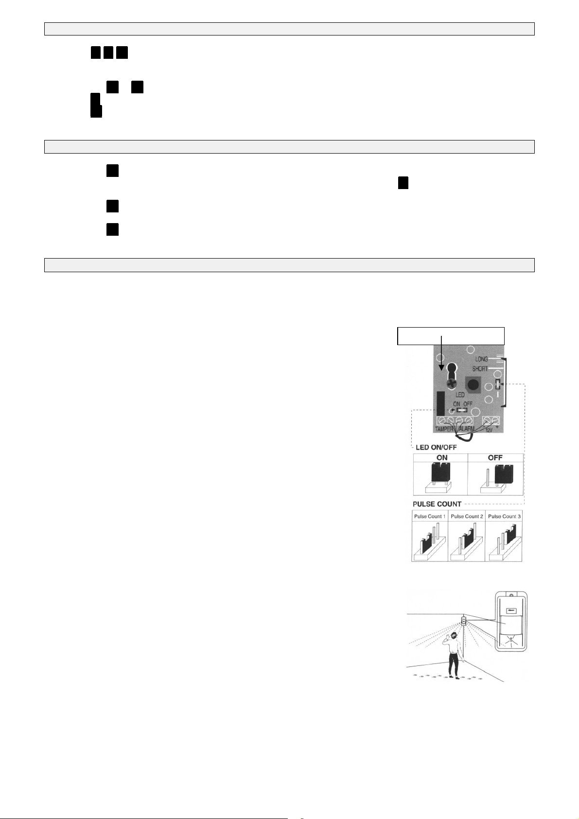
4.1.6.1 Pulse count
You can set PULSE jumper at position 1,2 or 3 corresponding to the desired pulse count
before an alarm will betriggered. Default = 2.
4.1.6.2 WALK-test
To disable LED indication, remove the LED jumper and place it on one pin only. To
activate LED indication, place LED jumper over both pins.
4.1.6.2.1 Mounting height
If motion detector is not mounted at 2.5m you can adjust like this:
1. Loosen the PC-Board holding screw. Slide the PC-Board so that the plastic pointer
on the right side is positioned at the appropriate scale position.
For higher than 2.5m => Slide PC-Board up
For lower than 2.5m => Slide PC-Board down
2. Tighten the PC-Board holding screw
3. Mount front cover
4. Walk through the entire protected area and observe the LED to ensure full coverage
Mounting screw
7
Page 8
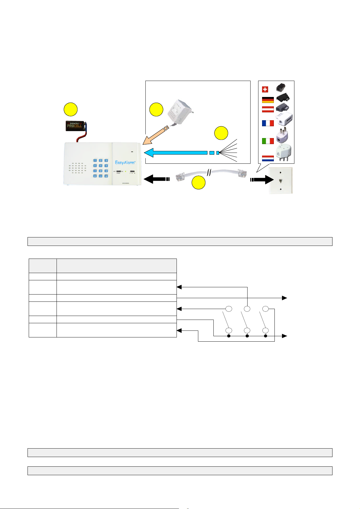
4.2 Operation with potential free alarm contacts (EasyAlarm BASIC)
2
1
4
3
4.2.1 Safety notes
Function switch must be shifted to OFFand telephone-cord must be disconnected before any wiring work is
done on the AC-adapter or connecting cable.
All contacts of the EXTport are on telephone circuit potential => therefore any applied alarm contact must be
potential free (relays or opto-coupler) and must have a isolation of lease 3.75kV accordingto regulation
EN60950.
All contacts have to be protected against any body contact
4.2.2 Installation
1. Slide function switch to OFF
2. Insert 9V battery into compartment on rear side of alarm unit
Please note:The telephone cord must be disconnected before openingthe battery compartment because otherwise
you can get in contact with the telecommunication voltage!
Operation withalarm contacts Details according tosection 5
3. Plug sensor-cord in one o the EXT/≂-port of alarm unit and connect potential free alarm sensor as following
FCC8/6
Plug
PIN 2: White wire (Output)
PIN 3: Black wire (Sensor-2 input)
CAN BE USED AS EMEGENCY MODE!
PIN 4: Red wire (+12V)
PIN 5: Green wire (Sensor-1 input)
PLUG&PROTECT-sensor
PIN 6: Yellow wire (GND)
PIN 7: Blue wire (Sensor-3 input)
CANNOT BE DISARMED!
4.2.2.1 Operation with only one alarm contact (Sensor-1)
If you need only one alarm contact you should use sensor-1-input. EasyAlarm®will auto-detect the contact-type (
Plug&Protect-Contact) and starts monitoring sensor-1 according to the state of the sensor-2-input at the time of power-up
(details according to section 4.1.4):
Sensor-1 is a normally closed contact => Connect Sensor-2-input to GND
Sensor-1 is a normally open contact => Leave Sensor-2-input open
4.2.2.2 Operation with up to three alarm contacts (NO or NC)
Select the appropriate contact to fit the monitoring!
Notes:
Sensor-1 monitoring can be disarmed (disable) or sensor-1 can be used for presence verification ( programming
according to section 5.1)
Sensor-2 monitoring can be disarmed (disable) or sensor-2 can be used as a emergency contact ( programming
according to section 5.2)
Sensor-3 monitoring CANNOT bedisarmed ( programming according to section 5.3)
Open ends of sensor-cord
Type of contact: Normally open (NO)
Normally closed (NC)
Potential free !
Sensor 2
Sensor 1
Sensor 3
(to AC-adpter)
Connect power supply
4. Connect the AC-adapter cable into the other EXT/≂-port of the alarm unit
Telephone connection
5. Plug enclosed telephone-cord into -Line-Jack ofalarm unit and connect it with the telephone network
If you share line withmodem/telephone please proceed according to section 10.6
8
Page 9
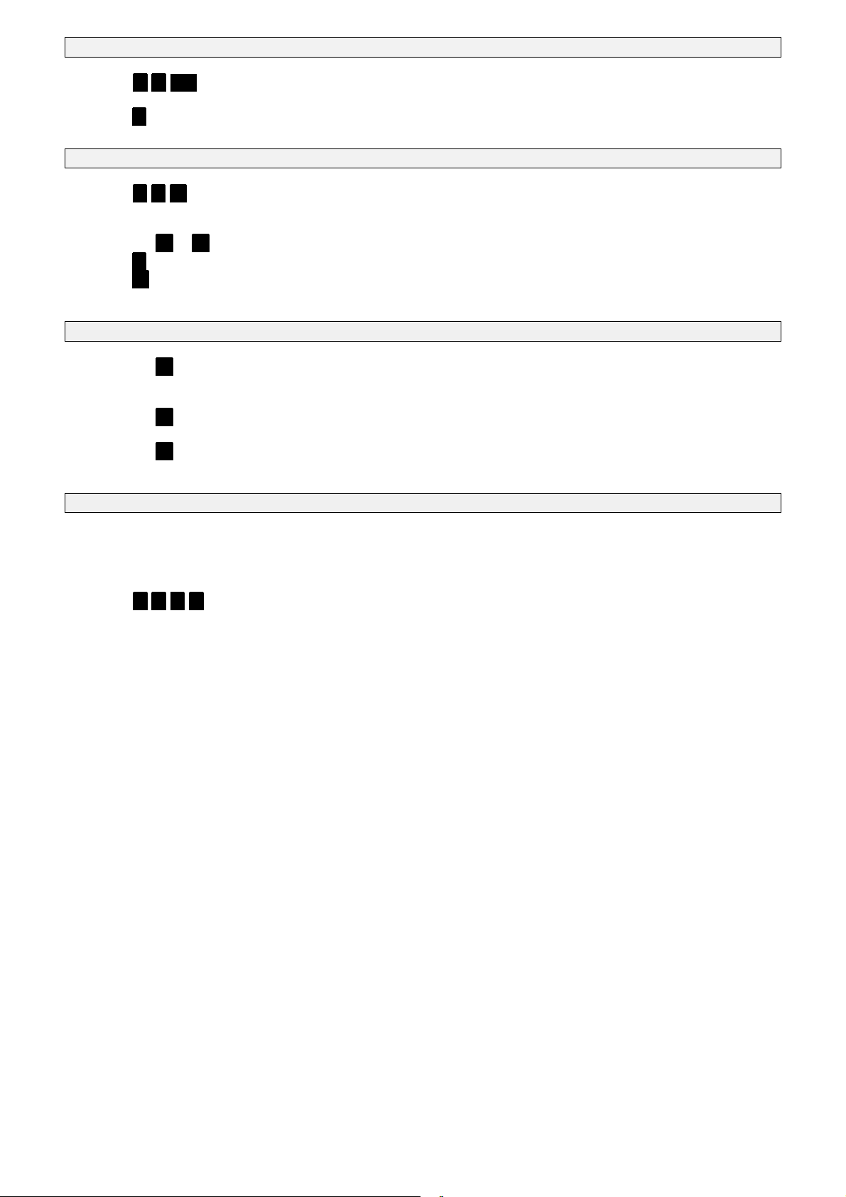
Program calling number(s) Details according to section 6.1
6. Slide function switch to PROG
7. Enter * * <n> (selected calling number: Standard n = 1..9)
Corresponding calling number will be announced, followed by message “to modify press star“
8. Press * and enter calling number
9. Slide function switch to OFF
Select user language / record individual message Details accordingto section 6.3
10. Slide function switch to PROG
11. Enter *. *. #.
Current individual messagewill be announced followed by “to modify press * , to stoppress # “
12. Select language for user announcements: (facultative)
Press key 1 to 4 to select user languages: 1 for German, 2for French, 3 for English GB, 4 for Italian
13. Press *. and start speaking
14. Press #. to finish recording, max. duration is 12 seconds
New individual message will be announced. You can repeat steps 15 to 16 until text isfine!
15. Slide function switch to OFF
Program PIN-code Details according to section 6.4
16. Slide function switch to PROG
17. Press key #.
You can prevent the alarm unitfrom unintended re-programming by pressing *. ..
18. Enter PIN-code (4 to 7digits)
19. Press key #.
20. Re-enter PIN-code for confirmation
21. Press key #.
New PIN-code will be announced
22. Slide function switch to OFF
Alarm unit is now readyfor operation Details according tosection 7
23. Slide selection switch to the requested position (I/II/III)
4.2.3 Test mode for sensor contacts
You can test the wiring as following:
1. Slide function switch to PROG
2. Enter *. *. *. *.
Any time a monitored sensor contact changesto alarm state you will hear the announcement”<n> activated”.
If the contacts changes to idle state you will hear “<n> deactivated.
3. Slide function switch to OFF
Notes:
<n> = 1/2/3 (depending on sensor)
Only sensors with contact type other than inactive (00) will be announced => see configuration in section 5.
9
Page 10
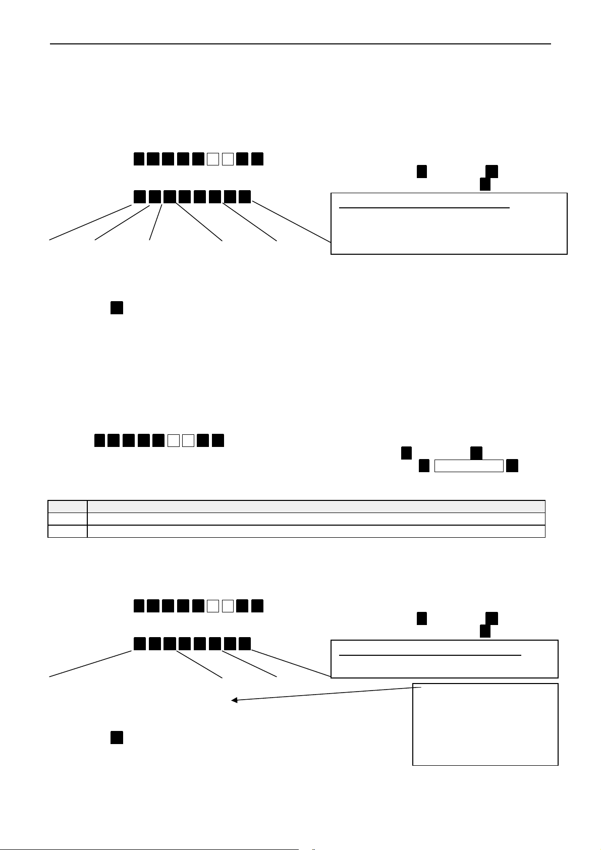
5. CONFIGURATION OF THE ALARM REGISTERS
Factory default for sensor
-
1 monitoring
Factory default for gong
-
function sensor
-
1
Note:
5.1 Sensor-1 monitoring
5.1.1 Sensor-1 as alarm contact
EasyAlarm
behaviour for sensor-1 as following:
Example: A normally closed contact shall trigger an un-delayed alarm with a hands-free-connection independent from
position of the selection switch.
1. Slide function switch to PROG
2. Enter sequence *. 9. 3. 1. 7 5 6 #. #.. .
Current register (bit 7 -> bit 0) will be announced followed by “to modify press *., to stop press #.“
3. If you want to keep current value proceed with step6. Otherwise start modifying register bypressing *..
4. Enter sequence 0. 0. 1. 0 0 0. 1. 1. .
R-Siren Entry-Delay Connect. mode Sensor on.. Type
0: off 0:off 0: Listening-in I / II / III 00: inactive
1: on 1:on 1: Hands-free 0 0 0 01: Normally open contact
5. Press key #. . 11: Normally closed contact
The new register (bit 7 -> bit 0)will be announced
6. Slide function switch to OFF
5.1.2 Sensor-1 for presence verification
You can also use sensor-1 to monitor missing activity (i.e. no motion detected within a certain period) => Alarm message:
„Emergency call due to sensor-1“. Therefore you have to activate time-out as below.
5.1.2.1 How to program presence verification time-out
Time-out for presence verification is factory set to 24h. If there isno activation within this period, an alarm is triggered
after a pre warning period of10 minutes (this period is indicated with a periodical loud beep tone).
®
auto-detects a Plug&Protect-sensor and starts its monitoring if the system is armed. You can define the
00 0 000 10, => un-delayed alarm in listening-in
connection only on all positions I/II/III
=> connector type: auto-type (plug&protect)
0: enabled 10: Plug&Protect (auto-detected at power-on)
1: disabled input-2 is open => Normally open monitoring
input-2 is closed => Normally closed monitoring
1. Shift function switch to PROG
2. Enter *. 9. 7. 1. 3 6 7 #. #. .
Current register value <n> will be announced followed by “to modify press *., to stop press #.“
3. If you want to keep current value proceed with step4. Otherwise modify register with *. New value <n> #..
The new register value <n> will be announced
4. Shift function switch to OFF
<n> Explanation
0 Presence verification is switched off (=Factory setting)
6..255 Time-out in steps of10 min. (min. 60min, max. 42.5h) => For example:n=144 (144*10min = 24 h)
5.1.3 Sensor-1 as entry-detector (Gong function)
A sensor-1 activity can also be signalled locally (Gong-function) according to the following procedure:
Example: Sensor-1 shall greet an incoming person with the pre-recorded individual message only on position I.
1. Slide function switch to PROG
2. Enter sequence *. 9. 3. 1. 7 3 1 #. #...
Current register (bit 7 -> bit 0) will be announced followed by “to modify press *., to stop press #.“
3. If you want to keep current value proceed with step6. Otherwise start modifying register bypressing *..
4. Enter sequence 0. 0. 0. 0 1 1. 1. 0. .
000 111 00
Unused Gong on.. Gong-type
000: I / II / III 00: Gong
0 1 1 01: --
0: enabled 10: Individual message
1: disabled 11: Beep loud
5. Press key #. .
The new register (bit 7 -> bit 0)will be announced
6. Slide function switch to OFF
If you do not want to
trigger an alarm on
position I you have to
disable alarm according to
section 5.1.1
10
Page 11
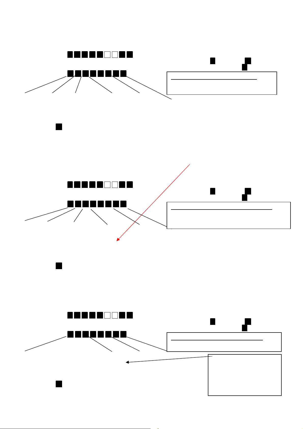
5.2 Sensor-2 monitoring
Fact
ory default for gong
-
function sensor
-
1
Note:
Factory default for sensor
-
2 monitoring
Factory default for emergency
-
call bysensor
-
2
5.2.1 Sensor-2 as alarm contact
Alarm function for sensor-2 in armed mode can be selected as following:
Example: Sensor 2 is a normallyclosed contact that should trigger an un-delayed silent alarm on position I/II
1. Slide function switch to PROG
2. Enter sequence *. 9. 3. 1. 7 5 7 #. #.. .
Current register (bit 7 -> bit 0) will be announced followed by “to modify press *., to stop press #.“
3. If you want to keep current value proceed with step6. Otherwise start modifying register bypressing *..
4. Enter sequence 0. 0. 0. 0 0 1. 1. 1. .
00 0 000 00, => inactive
R-Siren Entry-Delay Connect. mode Sensor on.. Type
0: off 0:off 0: Listening-in I / II / III 00: inactive
1: on 1:on 1: Hands-free 0 0 1 01: Normally open contact
0: enabled 10: Emergency-contact according to section 5.2.2
1: disabled 11: Normally closed contact
5. Press key #. .
The new register (bit 7 -> bit 0)will be announced
6. Slide function switch to OFF
5.2.2 Sensor-2 as emergency-sensor
If sensor-2 is enabled in section 5.2.1 as emergency-contact an emergency-call is triggered ifthe contact is in alarm
position for at least one second. An emergency call does not depend on the position ofthe selection switch and is also
active if the system is disarmed
5.2.2.1 Emergency call
1. Slide function switch to PROG
2. Enter sequence *. 9. 3. 1. 7 6 0 #. #.. .
Current register (bit 7 -> bit 0) will be announced followed by “to modify press *., to stop press #.“
3. If you want to keep current value proceed with step6. Otherwise start modifying register bypressing *..
4. Enter sequence 0. 1. 1. 0 0 0. 1. 1. .
0 1 1 000 11: => delayed alarm in hands-freemode.
Contact type: NC
R-Siren Entry-Delay Connect. mode Sensor on.. Type
0: off 0:off 0: Listening-in I / II/ III 00: inactive
1: on 1:on 1: Hands-free 0 0 0 01: Normally open contact
0: enabled 10: Plug&Protect (auto-detected at power up)
input-2 is open => Normally open monitoring
input-2 is closed => Normally closed monitoring
11: Normally closed contact
5. Press key # .
The new register (bit 7 -> bit 0)will be announced
6. Slide function switch to OFF
5.2.3 Sensor-2 as entry-detector (Gong function)
A sensor-2 activity can also be signalled locally (Gong-function) according to the following procedure:
Example: Sensor-2 shall announce an incoming person with a loud beep on position II.
1. Shift function switch to PROG
2. Enter sequence *. 9. 3. 1. 7 3 2 #. #...
Current register (bit 7 -> bit 0) will be announced followed by “to modify press *., to stop press #.“
3. If you want to keep current value proceed with step6. Otherwise start modifying register bypressing *..
4. Enter sequence 0. 0. 0. 1 0 1. 1. 1. .
000 111 00
Unused Gong on.. Gong-type
000: I / II / III 00: Gong
1 0 1 01: --
0: enabled 10: Individual message
1: disabled 11: Beep loud
5. Press key #.
The new register (bit 7 -> bit 0)will be announced
6. Shift function switch to OFF
If you do not want to
trigger an alarm on
position II you have to
disable alarm according to
section 5.2.1
11
Page 12
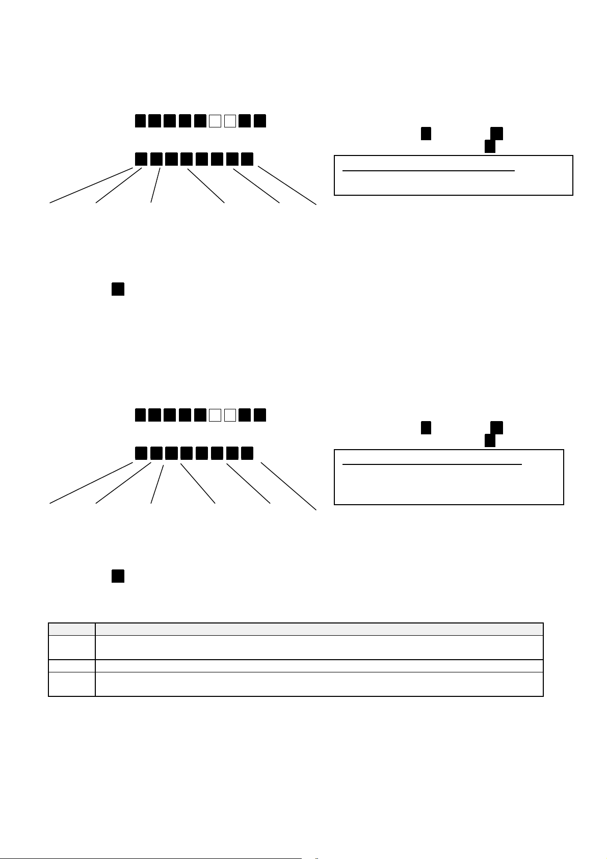
5.3 Sensor-3 monitoring
Factory default for sensor
-
3 monitoring
Factory default for acoustical monitoring
5.3.1 Sensor-3 as alarm contact
Note: if sensor-3 input is enabled as show below, you cannot disarm at any time!
Example: A normally closed contact shall trigger an un-delayed alarm with a hands-free-connection independent from
position of the selection switch.
1. Shift function switch to PROG
2. Enter sequence *. 9. 3. 1. 7 6 1 #. #..
Current register (bit 7 -> bit 0) will be announced followed by “to modify press *., to stop press #.“
3. If you want to keep current value proceed with step6. Otherwise start modifying register bypressing *.
4. Enter sequence 0. 0. 1. 0 0 0. 1. 1. .
00 0 111 00, => inactive on all positions I/II/III
R-Siren Entry-Delay Connect. mode Sensor on.. Type
0: off 0:off 0: Listening-in I / II / III 00: inactive
1: on 1:on 1: Hands-free 0 0 0 01: Normally open contact
0: enabled 10: Plug&Protect (auto-detected at power up)
1: disabled input-3 is open => Normally open monitoring
input-3 is closed => Normally closed monitoring
11: Normally closed contact
5. Press key #. .
The new register (bit 7 -> bit 0)will be announced
6. Shift function switch to OFF
5.4 Acoustical monitoring
The acoustical monitoring is enabled if selection switch is on position III. In case the alarm conditions is fulfilled a
listening-in connection is established without any delay If you want to change this factory default you can proceed as
following:
Example: Acoustical monitoring enabled on II and III starting a hands-free connection without delay.
1. Shift function switch to PROG
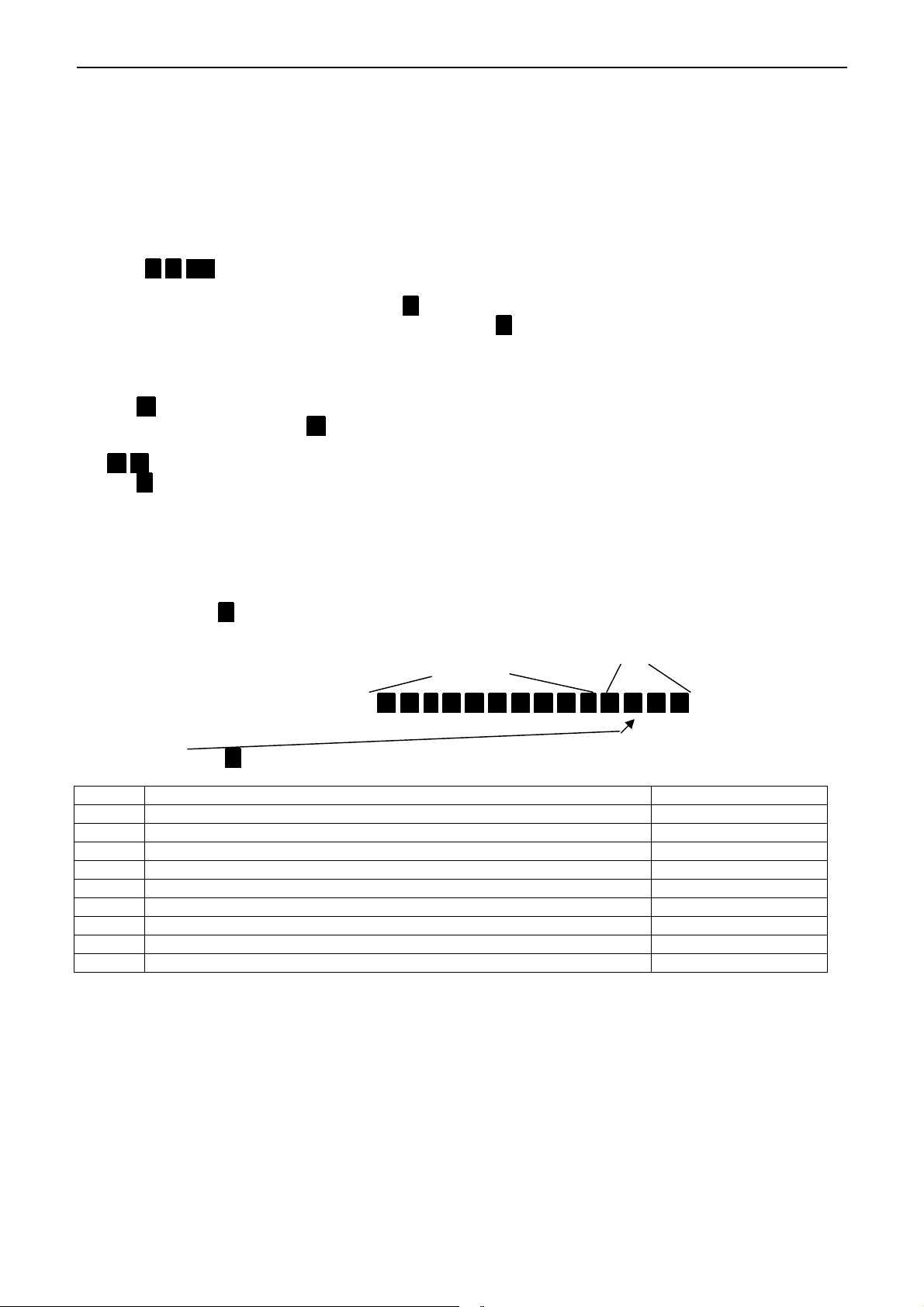
2. Enter sequence *. 9. 3. 1. 7 5 9 #. #..
Current register (bit 7 -> bit 0) will be announced followed by “to modify press *., to stop press #.“
3. If you want to keep current value proceed with step6. Otherwise start modifying register bypressing *..
4. Enter sequence 0. 0. 1. 1 0 0. 0. 1. .
00 0 110 01, => un-delayed alarm in listening-in
connection only on position III, inactive if disarmed
R-Siren Entry-Delay Connect. mode Sensor on.. Type
0: off 0:off 0: Listening-in I / II / III 00: Monitoring independent from arm/disarm state
1: on 1:on 1: Hands-free 1 0 0 01: Monitoring only in armed state
0: enabled
1: disabled
5. Press key #. .
The new register (bit 7 -> bit 0)will be announced
6. Shift function switch to OFF
The sensitivityof the acoustical monitoring depends on selected position of the selection switch:
Position Alarm conditions (Function switch auf ON)
I Low sensitivity (LOW) => Alarm will be triggered if the noise level exceeds several times within a long
period (approx. 8 activations)
II Medium sensitivity (MED)
III Highest sensitivity (HIGH) => Alarm will be triggered ifthe noise level exceeds a few times within a short
period (approx. 3 activations)
12
Page 13
6. PROGRAMMING
Important note:
All the programmed parametersremain storedeven without battery.
You can prevent your system from unintended re-programming according to section 6.4.1. If you use this
protection feature message„programming deactivated, PIN“ will be announced when the function switchis
on position PROG.
Three beep:Mains power loss AND battery low at the same time!
6.1 How to program new calling numbers
EasyAlarm
1. Slide function switch to PROG
2. Enter * * <n> (selected calling number: Standard n = 1..9)
3. If you like to change this calling number, press * , otherwise proceed with step 5
4. Enter new calling number. To delete an existing number enter * and proceed with step 5
5. Slide function switch to OFF
Notes:
Every keystroke will be acknowledged bya beep
Key #. programmes a dialling delay of5 seconds, provided it is entered between two digits, e.g. a delay is essential in
a private exchange (first digit + #. + callingnumber).
If your private exchange needs a flash pulse to start an internal call, following programming ispossible:
Key *. is used as separator for Point-ID protocol section 6.1.1.
If a programming error occurs, put function switch to OFF and repeat point 1 to 5.
Important notes:
Calling number 1 cannot be deleted due to safety reasons.
6.1.1 Point-ID (Contact-ID) alarm protocol
If the alarm should be transferred to a alarm organisation using the Point-ID (Contact-ID) protocol, the alarm number has
to be followed by key * and the customer-ID. EasyAlarm forwards the protocol to this alarm number and connects
hereafter to the following calling number in standard hands-free connection mode
®
supports nine calling numbers that can be programmed as follows:
Select number will be announced followed by “to modify press star“
2. #. followed bythe extension number.
Alarm number Customer-ID
074567890 3456
Example for programming the calling number: 0 7 4 5 6 7 8 9 0 * 3 4 5 6 .
Note:
The first character * , that follows the alarm number will not be transmitted (=> separator). The customer ID is a four
digit code. In case of an alarm the following codes are transmitted according to the <Alarm reason> and the <Zone>.
Code
602 Alarm due to cyclic test 900
602 Alarm due to remote programming "**#" 900
301 Alarm due to power failure 900
601 Alarm due to key-press (test-call) 900
132 Alarm due to noise monitoring 900
140 Alarm due to hardware sensor 1 901
140 Alarm due to hardware sensor 2 902
140 Alarm due to hardware sensor 3 903
120 Alarm due to emergency button 902
<Alarm reason> <Zone>
13
Page 14

6.2 Designation of the calling number sequence
if called party 3 does not acknowledge the alarm, the calling
6.2.1 Standard sequence
Alarm triggered Calling number 1
Alarm not acknowledged
by called party 1
Calling number 2
alarm not acknowledged
by called party 2 same for calling number 3 to 9
The alarm is acknowledged by pressing DTMF 0 ( section 7.7.5).
The alarm is passed tonext party immediately bypressing DTMF 8 or after connection time-out.
number sequence is repeated the number of programmed alarm
repetitions times (default value: two alarm repetitions,
programming see section 10.2)
6.2.2 How to program calling number sequence
1. Slide function switch to PROG
2. Enter * * 0.
Current calling number sequence will be announced followed by “to modify press * , to stop press # “
3. To maintainthe current programming, go to point 5. Otherwise enter *. .
4. Enter the desired sequence (max. 9 digits)
5. Slide function switch to OFF
Sample for programming calling number sequence:
a) ’123’ => calling number 1 will be dialled, followed by calling number 2, followed by calling number 3.
b) ’111133322’=> first calling number1 will be dialled (4 call attempts are made), followed bycalling number 3(3 call
attempts are made), followed by calling number 2 (with 2 call attempts).
Notes:
The callingnumber sequence is factory set to ‘123456789’, but a general reset according tosection 10.1 will NOT
RESET thecalling number sequence!
In case of an un-programmed or deleted callingnumber, the calling number sequence will continue with the next
number of the sequence.
If a dialled number is busy and another call attempt is programmed, the waiting period before re-dialling is 30 sec.
If the calling number changes within the sequence, dialling of a new number starts without delay
6.3 How to select user language / How to record individual message
An individual announcement can be recorded asfollows:
1. Shift function switch to PROG
2. Enter * * #.
Current individual message will be announced followed by “to modify press * , to stop press # “
3. Select language for user announcements: (facultative)
Press key 1 to 4 according to desired user language (i.e. 1=DE/2=FR/3=GB/4=IT)
4. Press * and start speaking
5. Press # to finish recording, max. duration is 12 seconds
New individualmessage will be announced
6. Shift function switch to OFF
Note:
Repeat step 3 and 5 until you are satisfied with individual message.
6.3.1 Remote recording of individual message during handsfree connection
1. Enter DTMF * * # #
Current individual message will be announced followed by “to modify press * , to stoppress # “
2. Select language for user announcements: (facultative)
Press DTMF 1 to DTMF 4 according to desired user language (i.e. 1=DE/2=FR/3=GB/4=IT)
3. Start recording by sending DTMF * , start talking (max. 12 s) and finish bysending DTMF # .
New individualmessage will be announced
4. Wait until the message “Abort” confirms the end of the programming
Note:
Remote recording can be enabled / disabled according to section 10.8.1.
14
Page 15

6.4 How to program PIN-Code
You can change remote access PIN-code as follows:
1. Slide function switch to PROG
2. Press #.
You can prevent the alarm unitfrom unintended programming by pressing * .
3. Enter desired PIN-code (4 to 7digits!)
4. Press #.
5. Re-enter PIN-code for confirmation
6. Press #.
If PIN-code is re-entered correctly it will be announced. If you selected program locking the additional
message „programming inactive: PIN” will be announced. Incase of anincorrect programming the message
announced „Error“ will not be stored=> old PIN-code remains active.
7. Slide function switch to OFF
6.4.1 Lock program mode
If you initiated programming new PIN-Code with key * the program mode is locked unless you unlock byre-entering
PIN-code. This feature prevents from unintentional reprogramming during operation.
6.4.2 Unlock program mode
Having the programming blocked as described in section 6.4.1, you can unlock as follows:
1. Slide function switch to PROG
Message „Programming inactive: PIN“ will be announced
2. Enter PIN-code and press #.
By enteringcorrect PIN-code you will hear a confirmation beep, otherwise message „Error“
3. Slide function switch to OFF
15
Page 16

7. OPERATION
7.1 Self check at power on
After power on the alarm unit checks battery, mains power and telephone-line conditions. If one of these tests fails an
appropriate message will be announced (batteryerror/power failure/line-check error).
Three beep:Mains power loss AND battery low at the same time!
Quickly handle the announce problem, otherwise the alarm functions are not guarantied.
7.1.1 Detection of wired sensor
EasyAlarm
sensor is activated for presence verification
Important notes:
By disconnecting the motion detector during the operation mode, an alarm is triggered followed by the
announcement: ”alarm due to sensor 1, sensor failure!”
By connecting the motion detector after the start up procedure of the alarmunit, an alarm istriggered followed by
the announcement: “alarmdue to sensor 1, sensor 1 activated!”
7.2 Arm / Disarm system
After power on EasyAlarm®automatically arms the system. During operation EasyAlarm®can be armed/disarmed
using the remote control or during any telephone connection using DTMF 7 and 9 .
7.3 Inactive waiting period
7.3.1 After power on or changing position of selection switch (exit delay)
EasyAlarm
triggering an alarm. An emergency call by pressing the emergency button is still possible.
®
detects the connected motion sensor automatically during the switching on procedure (factory setting). This
Announce “supervision activated “ or “supervision deactivated”
®
remains inactive for 20 seconds (LED is on continuously), to leave time to quit your room/house without
Note:
The entry/exit period can be adjusted according to section 10.3.
If there are unacknowledged alarms, their quantity and the reason of the last alarm will be announced.
If presence verification is activated, following announcement is made: "Presence verification activated".
Key Action
5 Announcement of the monitored functions (inactive waiting period will be restarted)
Bypass waiting period and change to inactive supervision mode
7
Attention: byswitching from activated to inactivated supervision mode, an announcement of the
supervision modes is made and the waiting period starts again.
Bypass waiting period and change to active supervision mode
9
Attention: byswitching from inactivated to activated supervision mode, an announcement of the
supervision mode is made and the waiting period starts again.
others Test-call will be made to the first calling number
7.3.1.1 Announcement of the supervision functions
The supervision functions can be activated or deactivated individually on each position of the selection switch
EasyAlarm
EasyAlarm
®
deactivated announcement: "Supervision I/II/III deactivated"
®
activated announcement: "Supervision I/II/III”
followed by the supervision mode of the activated type of monitoring:
acoustical monitoring announcement: "due to noise"
sensor-1 monitoring announcement: "due to sensor 1”
sensor-2 monitoring announcement: "due to sensor 2”
sensor-3 monitoring announcement: "due to sensor 3” .. “activated”
7.3.2 ..after an successful alarm
EasyAlarm
An emergency call is still possible during this period. Anykey-press results in a test call to the first calling number.
®
remains inactive for two minutes (LED is on continuously) to avoid too many alarms dueto sensor contacts.
16
Page 17
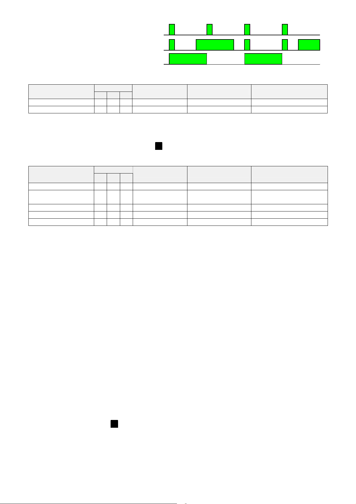
7.4 Supervision mode
Noise
Nois
4 seconds
4 seconds
LED: acoustical monitoring inactive
LED: acoustical monitoring activated
LED: inactive mode
4 seconds 4 seconds
7.5 Alarm
7.5.1 .. independent of alarm unit state (armed or disarmed)
Cause of alarm
Emergency (Sensor-2)
Sensor-3
1.) Default values without en without consideration ofuser specific programming in accordance to section 5
2.) Emergency call activation according to section 5.2.2: An emergency call will be triggered, if the button has been
activated for one second. After a pre alarm period of 20 seconds EasyAlarm®starts dialling calling number(s) and a
hands-free connection is established. During the pre warning period the alarm can be cancelled by pressing the
emergency button respectively by pressing key 0..
3.) Sensor-3 activation according to 5.3.1.
7.5.2 .. only if alarm unit is armed
„Default value“
Cause of alarm
Sensor 1
Presence verification
Sensor 2
Noise (Babyphone)
Mains power loss
4.) Sensor-1 activation according to 5.1.1.
5.) Sensor-1 can be used to verify if a person is present ( section 5.1.2), i.e. an alarm will be triggered if no motion is
detected within 24h. Before starting the alarm there is a pre warning period often minutes. If activation is detected
(motion detected or emergency button pressed) within this period, the alarm is cancelled, otherwise EasyAlarm
establishes a hands-free connection
6.) Sensor-2 activation according to 5.2.1.
7.) Noise monitoring according to 5.4: To avoid false alarm while acoustical monitoring, close windows and try to
eliminate sources of noise.
8.) EasyAlarm®monitors mains voltage and triggers an alarm ifpower loss is longer than 10 to 20 minutes (=> time-out
according to section 10.4). During a pre warning period of 1 minute the following message is announced „Alarm due
to power failure“. After this period EasyAlarm® dials the programmed number and a hands-free connection is
established. If EasyAlarm® does not detect mains power during start up the monitoring remains inactive => „Power
failure“ is announced ! As soon as mains power is detected, EasyAlarm® starts to supervise mains power
7.5.2.1 alarm release renewed
After an alarm EasyAlarm® remains inactive during a waiting period of two minutes. Only if at expiration of this
waiting period an alarm event occurs again, a new alarm is released.
Note:
After an alarms through to sensor-1/2/3 a renewed alerting comes off only if to the alarm contact returned to the state
of rest.
1)
3)
1)
4)
6)
7)
I II III
2)
I II III
5)
active on„Default value“
active on
Entry-Delay Connection mode Announcement
Delayed Hands-free connection „Emergencycall activated“
Un-delayed Listening-in connection „Alarm dueto sensor 3“
Entry-Delay Connection mode Announcement
Un-delayed Listening-in connection „Alarm due to sensor 1“
10 Minutes/30
Seconds
Hands-free connection
„Alarm dueto presence
verification“
Un-delayed Listening-in connection „Alarm due to sensor 2“
Un-delayed Listening-in connection „Alarm dueto noise“
1 Minute Hands-free connection „Alarm due to power failure “
®
7.6 Alarm delay / Pre warning period / Entry delay
An alarm can be delayed due to following reasons:
An alarm sensor in the area of the entrance must be delayed to have enough time to switch off the supervision mode
before EasyAlarm® dials the first calling number.
A pre warning announcement is used to avoid false alarms (i.e. technical error like power failure, unwanted
emergency calls). During the pre warning period the alarm can be cancelled bypressing the emergency button
respectively by pressing key 0..
Announcement: „Alarm acknowledged“
Notes:
The entry/exit period can be adjusted according to section 10.3.
If an alarm has been triggered by pressing the emergency button, cancellation of the alarm is only possible, if the
button has been released for min. 3 seconds before pressing it again.
7.6.1 Siren activation during pre warning period
If you use a siren ( section 11.2) which is activated as described in section 10.5.2, the pre alarm period is signalled bya
periodical siren tone.
17
Page 18

7.7 Phone connection
The colour of the indicator LED changes to orange during telephone connection.
7.7.1 Time-out
There is a timer running in the phone connection mode. Phone connection is kept up for two minutes in case of alarm call,
and ten minutes in case of test call. Ten seconds before disconnection, the called person hears the announcement “abort”.
He/she can restart timer using DTMF 3 at any time.
7.7.2 Announcements
At the beginning of each phone connection the following information will be announced: Individual message followed by
the cause of alarm and the instruction to acknowledge alarmby pressing DMTF 0 . In a Listening-in connection you get
announcement: „to speak press 1“. This announcement is repeated every 8 seconds, until a tone-dialling command is
entered.
Notes:
At the beginning of any phone connection battery state will be checked and announced if low
At the beginning of any phone connection battery state and main voltage are checked. In case a test is negative an
appropriated message will be announced.
The numbers of unacknowledged alarms is announced.
7.7.3 Listening-in connection
Possible tone-dialling commands during the listening-in connection
DTMF => Every valid command will be signalled
0 Terminate phone connection and acknowledge alarm
1 Switching to hands-free mode andrestart connection time-out
2 Repeat announcements (Individual message / Cause of alarm)
3 Restart connection time-out (2minutes)
4 Deactivate output (i.e. switching offalarm siren)
5 Announcement of current supervision mode as well as condition of the output
6 Activate output (i.e. switching on the alarm siren)
7 Change to inactive supervision mode (I, II, III)=> monitoring for noise, sensor-1, sensor-2, mains failure and
presence verification inactive. Emergency call and sensor-3 alarm are still possible.
8 Terminate phone connection without acknowledgment
9 Change to active supervision mode (I, II, III) => All monitoring functions re-activated
* * 0 Announcement of callingnumber sequence
* * n Announcement of calling number n(n = 1..9)
Following tone-dialling command can be used for remote programming, provided the programming is not blocked (
section 10.6)
* * # Trigger an alarm for test reasons Cause ofalarm announcement "alarm due to programming"
* * <n> * followed bythe new calling number announcement and change of calling number n
* * # # Record individual message => according to section 6.3.1.
7.7.3.1 Use of siren during listening in connection
The activation of a siren ( section 11.2) can be done either manually during a listening-in connection using DTMF 6 or 4
or automatically in accordance to the reason ofthe alarm ( programming section 10.5.2).
7.7.4 Hands-free connection
The commands during hands-free connection are identical to the commands bylistening in connection, except DTMF 1 .
Important note:
Hands-free connection must be terminated using DTMF 0 or 8 . Otherwise a busy tone signal appears until
phone connection is terminated due to time-out.
By selecting hands-free connection an activated siren (optionally) is automatically deactivated. If requested, the
siren can be activated or deactivated by DTMF 6 or4 .
7.7.4.1 Adjustment of hands-free volume
During hands-free connection you can increase volume bypressing local key #. or decrease bypressing locale key *..
Level can be adjusted in fifteen steps (1dB each) and remains stored.
7.7.5 Acknowledge alarm / Terminate connection
A called party can choose between acknowledgment bypressing DTMF 0 or passing on alarm to next party in calling
number sequence bypressing DTMF 8 .
Important notes:
There is no alarm repetition, ifan alarm is triggered by pressing any key of thealarm unit (test call).
An alarm can be confirmed andterminated by pressing key 0. of the alarm unit or by pressing the wireless
emergency button for a second time.
If the alarm is programmed toa pager, the called person can confirm alarm during remote-access after
dialling-in.
7.8 Alarm repetition
If an alarm has not been acknowledged bypassing all the calling numbers in the sequence, a number of alarm repetitions
can be programmed ( programming 10.2). Factory setting: two alarm repetitions.
18
Page 19

7.9 Test call
If alarm unit is switched to ON it is possible to start a test call as follows:
1. Select calling number by pressing key <n> (n= 1. .. 9 )
Announcement: „Calling number <n>“ => Ifselected calling number is not programmed themessage
“Error” will be announced andthe first calling numberwill be dialled instead
2. Wait until hands-free connection is established and speak
3. Terminate phone connection by pressing 0. or slide function switch to OFF
Notes:
After ten minutes phone connection will automatically terminate if called party does not give any tone-dialling
commands (i.e. called subscriber can disconnect using DTMF 0 or restart timer using DTMF 3 ).
During inactive waiting period after power on key 9. and 7. activate or deactivate the monitoring of the
supervision. Key 5. starts the announcement of the current supervision mode.
The volume of hands-free connection can be adjusted as described in section 7.7.4.1
7.10 Dialling-in (check call)
If the alarm unit is switched to ON you can dial in from any telephone set as follows:
1. Dial phone number of the EasyAlarm®
2. Let it ring for two ringing cycles and disconnect (hang up)
3. Redial after 20 seconds => EasyAlarm® answers call after two ringing cycles and waits for the PIN-Code
After entering the correct PIN-Code EasyAlarm® establishes a listening-in connection
Announcement „to stop press 0, to speak press1“
If no tone-dialling command is entered, the phone connection will be terminated after two minutes connection time-out.
The supervised person can also terminate the phone connection bypressing the emergency button.
Important: In case that there are unconfirmed alarms, the quantity as well as the last reason of the alarm will be
announced! An unacknowledged alarm will be confirmed by entering DTMF 0 !
Notes:
The two-step dialling in procedure is for securityreasons to avoid detecting of the alarm unit coincidently byan
unknown caller. Direct dialling in as well as other number of ringing cycles can be selected ( section 10.7)
If the PIN-code is incorrect ornot entered within 15 seconds, EasyAlarm® disconnects after the announcement „PIN
error, abort“ => try again and enter correct PIN.
PIN-code is factory set to 9797. For safety reasons we recommend changing PIN-code and program your individual
code according to the manual.
If a successful dialling-in should be signalled with five gong-signals (to alert/inform the supervised person),
EasyAlarm® can be programmedaccording section 10.7.3.
7.11 Answering an incoming call
An incoming call, signalled by a parallel connected phone, can be answered as follows (Function switch ON):
7.11.1 ..by pressing the emergency button
a hands-free connection is established => Disconnect by pressing the emergency button once again.
7.11.2 ..by pressing any key of the alarm unit
a hands-free connection is established => Disconnect by pressing key 0..
19
Page 20

8. USEFUL NOTES
8.1 Tone-dialling command
If you want to use EasyAlarm® to its full potential a tone-dialling telephone isnecessary. Nowadays most of the
telephones in use are working on tone dialling, also called DTMF or in-band signalling. Older telephones are using pulse
dialling. In case there is no tone-dialling telephone available, the features shown in section 7.7.3 cannot be used
Note:
An acoustic coupler can be purchased in electronic shops.
8.2 User information
8.2.1 Signals (beeps)
A single beep tone is used as a confirmation
Three beep:Mains power loss AND battery low at the same time!
8.2.2 Announcement audible in loudspeaker of EasyAlarm®
Announcement Message / Cause
„Individual message“ First message in case of an alarm
Abort Disconnection caused from the change of the position of the selection switch
Alarm due to presence
verification
Alarm acknowledged Disconnection
Battery error Battery is low=> batterytest after power on
Calling number n Calling number n (=1..9)
Calling number error First calling number in the calling number sequence is not programmed
Calling number sequence Calling number sequence
Emergency call activated Emergency call, initiated by emergency button
Emergency call deactivated,
alarm acknowledged
Error Incorrect programming => the old value remains stored
Line check error Telephone line check after power on was negative => dial tone missing
Output activated The output is activated after power on.
PIN Request to enter PIN-Codes by locked programme
Power failure Mains power missing => Mains power is tested after switching on the unit
Presence verification activated Motion sensor is set to presence verification
Programming deactivated: PIN Request to enter PIN-Code to unlock programming
Supervision (I/II/III) <due to
noise/sensor n>activated
Supervision (I/II/III) activated Announcement in active supervision mode at current position of the selection switch
Supervision (I/II/III) deactivated Announcement in active supervision mode at current position ofthe selection switch
to modifypress * , to stop press # Recording of individual message
Unacknowledged alarms: n Quantity of unacknowledged alarms
8.2.3 Announcements audible in the handset of called subscriber
as well as during hands-free connection in loudspeaker of EasyAlarm®
Announcement Message / Cause
„Individual message”
Abort Phone connection will be terminated
Alarm due to noise Alarm triggered bynoise activity (Note: according to selection switch position
Alarm due to presence
verification
Alarm due to programming A test call was initiated due to remote programming ( section 10.8.2)
Alarm due to sensor n
sensor n activated
sensor failure
Battery error Battery is low=> batterytest before phone connection is established
Emergency call activated Emergency call, initiated by emergency button
Emergency call due to sensor Emergency call triggered due to loss of presence verification
Output <activated/ deactivated>
PIN Request to enter PIN-Code after dialling in (remote access)
PIN error, abort Wrong PIN-code => Phone connection terminated
Power failure Mains power loss => Mains power is tested every time before phone connection is
Triggered emergency call due to loss of presence
Emergency call confirmed
Announcement of the monitored alarm functions at current position of the selection
switch (I/II/III)triggered bypressing key 5. during the inactive waiting period(
section 7.3.1.1)
(I/II/III)
(I/II/III)
First message in case of an alarm or reaction on DTMF 2 .
I,II,III the alarm can be delayed)
Triggered emergency call due to loss of presence
Reason ofalarm: alarm contact n.
sensor n is in alarm mode
disconnection of sensor during operation
confirmation of < DTMF 6 / DTMF 4 > ( section 11.4)
established
20
Page 21

Programming acknowledged Successful remote programming of a calling number or calling number sequence
Programming, abort Faulty remote programming of a calling number or calling number sequence
Sensor n activated Announcement if sensor n isstill in alarm mode
Supervision (I/II/III) < due to
noise / sensor n> activated
Supervision (I/II/III) activated
Supervision (I/II/III) deactivated
Unacknowledged alarms: n Quantity of unacknowledged alarms
Confirmation of DTMF 5 : announcement of the activated supervision functions,
indicating the supervision modes in accordance to the position of the selection
switch (I/II/III)
Confirmation of DTMF 9 : Switch to active supervision mode an announce
monitoring functions at current position of the selection switch (I/II/III)
Confirmation of DTMF 7 : Switch to inactive supervision mode an announce
monitoring functions at current position of the selection switch (I/II/III)
8.3 Functional checks
8.3.1 Test-call
We stronglyadvise to make a test-call to check functionality of EasyAlarm® before starting operation.
8.3.2 Test alarm functions
Even though the alarm unit is maintenance free (except the battery) a periodical function test should be carried out,
especially:
Emergency button
Wired sensors
Acoustical monitoring
8.4 Battery check / replacement
If the announcement „Battery error“ is initiated after switching on EasyAlarm®, the battery should be replaced
immediately as follows:
1. Slide function switch to OFF
2. Disconnect EasyAlarm® from the telephone network, by removing the telephone cord
3. Open battery compartment and remove old battery
4. Insert newbattery and close battery compartment
5. Reconnect telephone cord to EasyAlarm®
Notes:
Always use fresh 9V-batteries
Dispose the old battery properly
8.5 Maintenance
Slide function switch to OFF and remove telephone cord. Clean EasyAlarm® ifnecessary using a moistened cloth and dry
it afterwards.
Note:
Do not use cleaning agents or solvent
21
Page 22

9. TROUBLE SHOOTING / ERROR HANDLING
Most problems can be checked and solved with help ofthe following chart. Ifthe problem remains after consulting this
chart in details, please get in touch with your local dealer or contact the info line of your country, see section 12.3.
9.1 Telephone connection / Telephone communication
Symptoms Cause and /or remedy
LED is not lit after switching ON Replace battery
Announcement „programming deactivated:
PIN“ byan attempt of reprogramming
Announcement „Beep Beep Beep“
Announcement „battery error”
Announcement „power failure” Power failure, transformer not connected
Announcement „line check error “
No dial tones are audible during test call =>
no tones are audible during the dialling
procedure
Test call does not call first calling number in
the callingnumber sequence:
Announcement „calling number error“
Test call does not establish phone
connection: Announcement „calling number
n“ => dial tone audible
Remote access using dialling-in not possible
=> EasyAlarm® is not responding to the
call
Remote access using dialling-in not possible
=> disconnection after entering of PIN-code
EasyAlarm® does not react on tone-
dialling commands
Programming function is locked => to be unlocked according to section
6.4.2
Mains loss and low battery at the same time!
Battery is low => replace battery
No dial tone has been detected:
Unit is not connected with the telephone network
Telephone network failure
Another telephone working on the same phone line is occupying the
line already
Plug in telephone cord
Check the telephone cord
Start test-call with different telephone
Calling number (n=2..9) is not programmed => Callingnumber 1 was
dialled instead
Calling number is wrong
Called party is not answering the phone
The dialling function is programmed for the two step modus (
section 10.7.2)
Wrong PIN-code entered => call again
Current telephone does not support tone-dialling commands or has not been
configured => for example pulse dialling
9.2 Motion detector used as an alarm-sensor (sensor-1/2)
Symptom Cause and / or remedy
LED is on during WALK TEST, but no
alarm is triggered
WALK TEST has been set, but LED is noton Power supplyof the motion detector is missing (=> check cable,
There is no motion and the WALK TEST
LED is not on, but alarming with periodical
announcement „alarm sensor n“ is spoken
„Alarm dueto sensor n“is announced, but
the motion detectorhas been temporarily
deactivated
Inactive waiting period by switching on the unit or between two alarms
is not expired
Supervision has been temporarily deactivated (deactivation)
Supervision isdeactivated at current position of the selection switch
(I/II/III) ( section 5.1)
Motion detection is programmed to verify presence ( section
5.1.2.1), analarm is only triggered if no motion is detected over a
programmed time.
Only sensors with contact type set to other value than inactive (00) will
be announced => see configuration in section 5.
Test mode => check section 4.2.3
connector and power supply)
Power supplynot on since twominutes (stabilize time of PIR-motion
detector)
Power supplyof the motion detector is missing (check cable, connector
and power supply) => further announcement „power failure “
The motion detector has been connected (additional announcement
„sensor 1 activated“ or disconnected (additional announcement “sensor
failure”) after power on => factory setting automatically recognizes a
connected Plug&Protect-motion detector
The power supply of the unit has been cut off for a short period
The function switch has been switched to PROG or OFFafter
temporarily deactivation.
22
Page 23

9.2.1 Motion detector activated for presence verification
Symptom Cause and / or remedy
LED is on during WALK TEST, but no
alarm is triggered
WALK TEST has been set, but LED is noton Power supplyof the motion detector is missing (=> check cable,
Alarming with announcement „emergency
call activated, sensor 1 activated “
Alarming with announcement „emergency
call activated, sensor failure “
In case of presence verification an alarm is only triggered, if no
motion has been detected over the programmed period ( time-out
can be selected according to section 5.1.2.1)
connector and power supply)
Power supplynot on since twominutes (stabilize time of PIR-motion
detector)
Motion detector has been connected after the unithas been switch on!
Motion detector has been disconnected after the unit has been switch
on!
9.3 Sensor-1-contact
Symptom Cause and /or remedy
Sensor-1 does not trigger an alarm Inactive waiting period byswitching on the unit or between two alarms
is not expired
Supervision has been temporarily deactivated (deactivation)
Supervision isdeactivated at current position of the selection switch
(I/II/III) ( section 5.1)
Motion detection is programmed to verify presence ( section
5.1.2.1), analarm is only triggered if no motion is detected over a
programmed time.
Test mode => check section 4.2.3
„Alarm dueto sensor 1“ is announced, but
the motion detectorhas been temporarily
deactivated
The power supply of the unit has been cut off for a short period
The function switch has been switched to PROG or OFFafter
temporarily deactivation.
9.4 Sensor-2-contact
Symptom Cause and /or remedy
Sensor-2 does not trigger an alarm Inactive waiting period byswitching on the unit or between two alarms
is not expired
Supervision has been temporarily deactivated (deactivation)
Supervision isdeactivated at current position of the selection switch
(I/II/III) ( section 5.2)
Sensor-2 is activated as an emergency button ( section 5.2.2)
Test mode => check section 4.2.3
„Alarm dueto sensor 2“ is announced, but
the motion detectorhas been temporarily
deactivated
The power supply of the unit has been cut off for a short period
The function switch has been switched to PROG or OFFafter
temporarily deactivation.
9.5 Sensor-3-contact
Symptom Cause and /or remedy
Sensor-3 does not trigger an alarm Inactive waiting period byswitching on the unit or between two alarms
is not expired
Supervision has been temporarily deactivated (deactivation)
Supervision isdeactivated at current position of the selection switch
(I/II/III) ( section 5.3)
Contact is still in alarm position. A new alarm can onlybe triggered,
after the contact returns to its rest position
Test mode => check section 4.2.3
9.6 Acoustical monitoring
Symptom Cause and /or remedy
noise is not triggering an alarm Factory setting supports monitoring of acoustics only on pos. III of
selection switch. ( programming can be altered, see section 5.4)
The unithas been deactivated by DTMF 7 => LED alternatively 4s
on / 4s off
By switching on the unit or after triggering an alarm, the acoustical
monitoring isnot active during the waiting time of 20 seconds (
section 7.3)=> LED is lit constantly during the waiting time!
Depending on the position of the selection switch, an alarm is triggered
with a different delay. Every time the noise exceeds the pre set level,
the LED is on. ( section 7.4)
23
Page 24
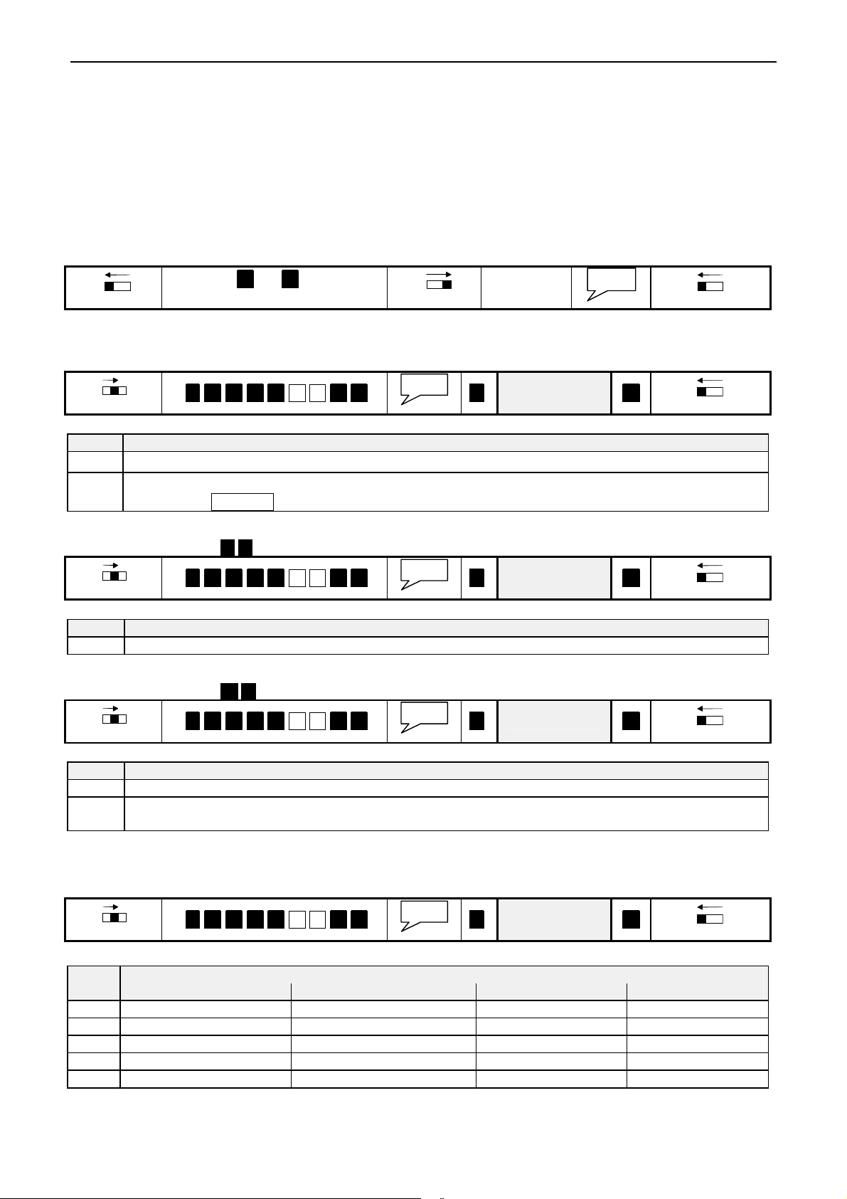
10. SPECIAL PROGRAMMING
PROG
PROG
PROG
PROG
PROG
PROG
PROG
PROG
PROG
PROG
Prog. 2
Important notes:
All parameters remainstored even if EasyAlarm® is switched off or without battery. Therefore
reprogramming is only essential if parameters have to be changed.
Programming mode can be locked to secure against unintended programming during operation (section 6.4.1).
If lock is activated, the announcement „programming inactive: PIN“ will be announced if function switch is
shifted to PROG.
Attention: Changing theseparameters below does influence the operating mode. Therefore onlynecessary
parameters should be changed. Please test behaviour before putting the unit back intooperation!
A programming errorcan be corrected by repeating the programming steps accordingly.
10.1 Factory settings (Default-Values)
EasyAlarm® can be reset to default values as follows:
OFF ON
Keep 3 and # pressed
simultaneously
10.2 Alarm repetition
An alarm is triggered, as soon as the alarm criterion is fulfilled and the waiting periodhas expired. In some cases it might
be useful to repeat an alarm as long until an acknowledgement isreceived.
OFF ON
*. 9. 7. 1. 3 5 3 #. #. *. Value #.
OFF ON
PROG
Value
Release keys
OFF ON
OFF ON
Value Comment
0
1..9
EasyAlarm
EasyAlarm® starts calling the calling numbers within the calling number sequence until the alarm is
®
calls the alarm numbers within the calling number sequence just once
confirmed by DTMF 0 or until the programmed value is reached! (factory setting: Value=2)
10.3 Entry / Exit period
The appropriated register 4 8 an be read-out or modified as follows:
OFF ON
*. 9. 7. 1. 3 4 8 #. #. *. Value #.
Value
OFF ON
Value Comment
0..255 Time in seconds (factory setting: Value=20)
10.4 Mains power loss timeout
The appropriated register 6 3 can be read-out or modified as follows:
OFF ON
*. 9. 7. 1. 3 6 3 #. #. *. Value #.
Value
OFF ON
Value Comment
0 Mains power loss alarm disabled
1..255 Period for mains power loss, before a alarm is activated : in 10 minute steps ! (deviation: -10/+0min)
(factory setting: Value=2, i.e.. alarm is triggered if the mains voltage precipitates during 10..20min).
10.5 Signalling
10.5.1 .. through alarm unit
It is possible to signal the inactive waiting period with one beep every two seconds. Proceed as follows:
OFF ON
*. 9. 7. 1. 3 0 5 #. #. *. Value #.
Value
OFF ON
0
1
2
3
4
24
Signalling..Value
Mains loss at power-on Selected mode after power-on Exit Beep every 2 sec. Entry: 2 Beep
Page 25
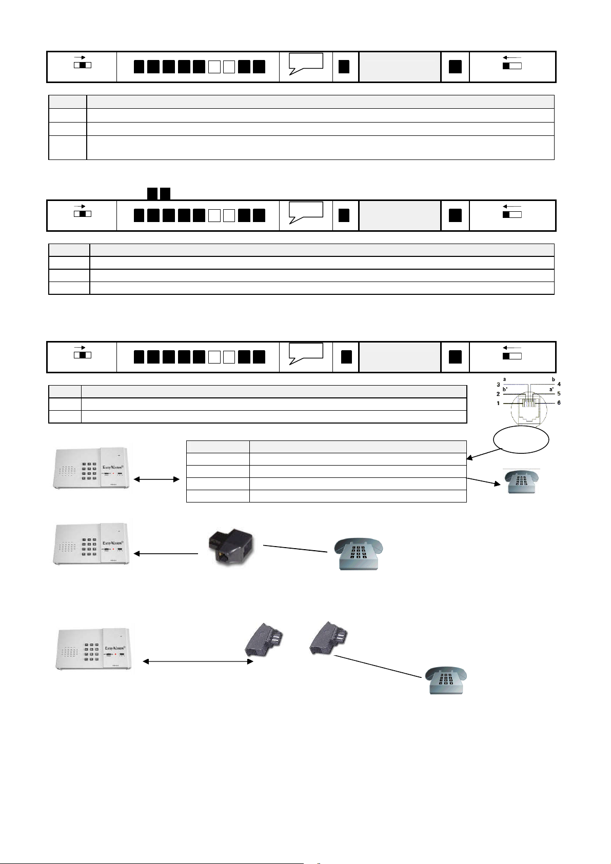
10.5.2 .. through external siren
PROG
PROG
PROG
PROG
PROG
PROG
post connected phone
post connected phone
IN
OUT
Operating mode of the siren can beprogrammed as follows:
OFF ON
*. 9. 7. 1. 3 0 7 #. #. *. Value #.
Value
OFF ON
Value Comment
0 No signalisation bythe siren (=factory setting)
1 periodical signalisation of the delay for exit/ entry
2 periodical signalisation of the delay for exit/ entry
permanent siren tone in case ofan alarm during listening-in connection (exception: silent panic call)
10.5.3 .. during phone connection (announcements)
The cause of alarm will berepeated every8 seconds during connection until a DTMF command isreceived. This
corresponding register 2 0 can be read out or modified as follows:
OFF ON
*. 9. 7. 1. 3 2 0 #. #. *. Value #.
Value
OFF ON
Value Comment
0 no repetitions => one announcement a the beginning ofthe connection
1..254 Cycle of repetition in steps of seconds (factory setting=8) i.e: Value=30 announcement every 30 seconds
255 Special case: Individual message announced just once (WITHOUT cause of alarm)
10.6 Shared line with telephone/modem
If you want to use EasyAlarm®in combination with a downstream telephone/modem you must set dialling delayas
follows:
OFF ON
*. 9. 7. 1. 3 2 4 #. #. *. Value #.
Value
OFF ON
<n> Comments
0 No dialling delay (=factory setting)
1 Dialling delayed (=Option PLUS)
10.6.1 Wiring with cord with end-sleeves
-LINE End-sleeves of telephone cord
PIN 2: OUT Black => to downstream modem/phone b’
PIN 3: IN Red <= from PSTN (Terminal a)
PIN 4: IN Green <= from PSTN (Terminal b)
PIN 5:OUT Gelb => to downstream modem/phone a’
10.6.2 Wiring Switzerland with T+T- SW06
1. Plug adapter SW06 into wall plate
2. Connect FCC-cord between alarm unit and adapter SW06
3. Plug „post connected” phone into T+T-Jack of adapter SW06
10.6.3 Wiring Germany with TAE-N-Plug
TAE-N-Plug
1. Plug adapter TAE-N into first N-Jack of wall plate
2. Connect FCC-cord between alarm unit and adapter TAE-N
3. Plug „post connected” phone into TAE-F-Type-Jack of wall plate
PSTN
TAE-F-Plug
25
Page 26
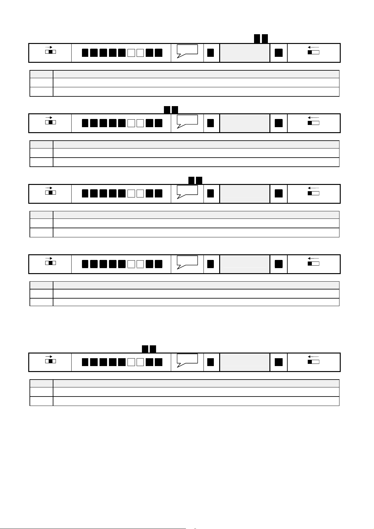
10.7 Dialling-in (Remote-access)
PROG
PROG
PROG
PROG
PROG
PROG
PROG
PROG
PROG
PROG
10.7.1 Program ringing cycles
The number of ringing cycles until EasyAlarm® answers the call is defined inregister 4 7 :
OFF ON
*. 9. 7. 1. 3 4 7 #. #. *. Value #.
Value Comment
0
2..9
EasyAlarm® does not answer any call
EasyAlarm® answers call after Valueringing cycles (factory setting: Value=2)
10.7.2 Dialling in sequence
Behaviour on dialling-in mode is defined in register 7 0 that can beread out or modified as follows:
OFF ON
*. 9. 7. 1. 3 7 0 #. #. *. Value #.
Value Comment
0
1
EasyAlarm® answers call directly after the programmedringing cycles (=factory setting)
EasyAlarm® answers call after a two-step dialling -in sequence
10.7.3 Connection mode after dialling-in
Phone connection mode after dialling-in is defined inregister 7 1 that can beread out or modifiedas follows:
OFF ON
*. 9. 7. 1. 3 7 1 #. #. *. Value #.
Value
Value
Value
OFF ON
OFF ON
OFF ON
Value Comment
0
1
EasyAlarm
EasyAlarm
®
does not signal a successful dialling in and switches in listening-in connection (=factory setting)
®
establishes hands-free connection announcedby three gong signals.
10.7.4 Handling of incoming calls
Answering incoming call bypressing the emergency button or any key can be selected as follows:
OFF ON
*. 9. 7. 1. 3 7 2 #. #. *. Value #.
Value
OFF ON
Value Comment
0
EasyAlarm
®
is not responding by activation of the emergency button or any key of the alarm unit
1 The call can be received bypressing the emergency button or any key of the alarm unit (=factory setting)
10.8 Remote programming
The callingnumbers as well as the sequence of the callingnumbers are programmable during phone connection. This
function is disabled (factory setting), but can be enabled as follows:
10.8.1 Enabling of remote programming
Remote programming is defined in register 7 6 that can beread out or modified as follows:
OFF ON
Value Comment
0
1
EasyAlarm® cannot be remote programmed (=factory setting)
EasyAlarm® is ready for remote programming
*. 9. 7. 1. 3 7 6 #. #. *. Value #.
Value
OFF ON
26
Page 27

10.8.2 Remote programming of calling number and calling number sequence
If remote programming is enabled calling numbers/sequence can be re-programmed during phone connection:
1. Enter DTMF * * n (n => see chart below)
Current calling number/ calling number sequence will be announced. If you want to change, continue at point
two. otherwise enter DTMF # .
2. Enter DTMF *
3. Enter newnumber/sequence
After entering of the last digits, wait ten seconds. Newnumber/ sequence will be announced, followed by the
request to enter DTMF n to confirmchange. If you do not confirm within 10 seconds or if another key is
pressed the message „programming: abort“ will be announced. In this case the old value remainsactive.
<n> Comment Programming according to
0 Calling number sequence (max. 9 digits) Section 6.2
1 Calling number I (max. 24 digits)
2 Calling number II (max. 24 digits)
3 Calling number III (max. 24 digits)
# SPECIAL - CASE: Phone connection is terminatedand a test call is initialised with the current calling number
sequence and calling numbers => announcement: “Alarm due to programming“
Section 6.1
27
Page 28
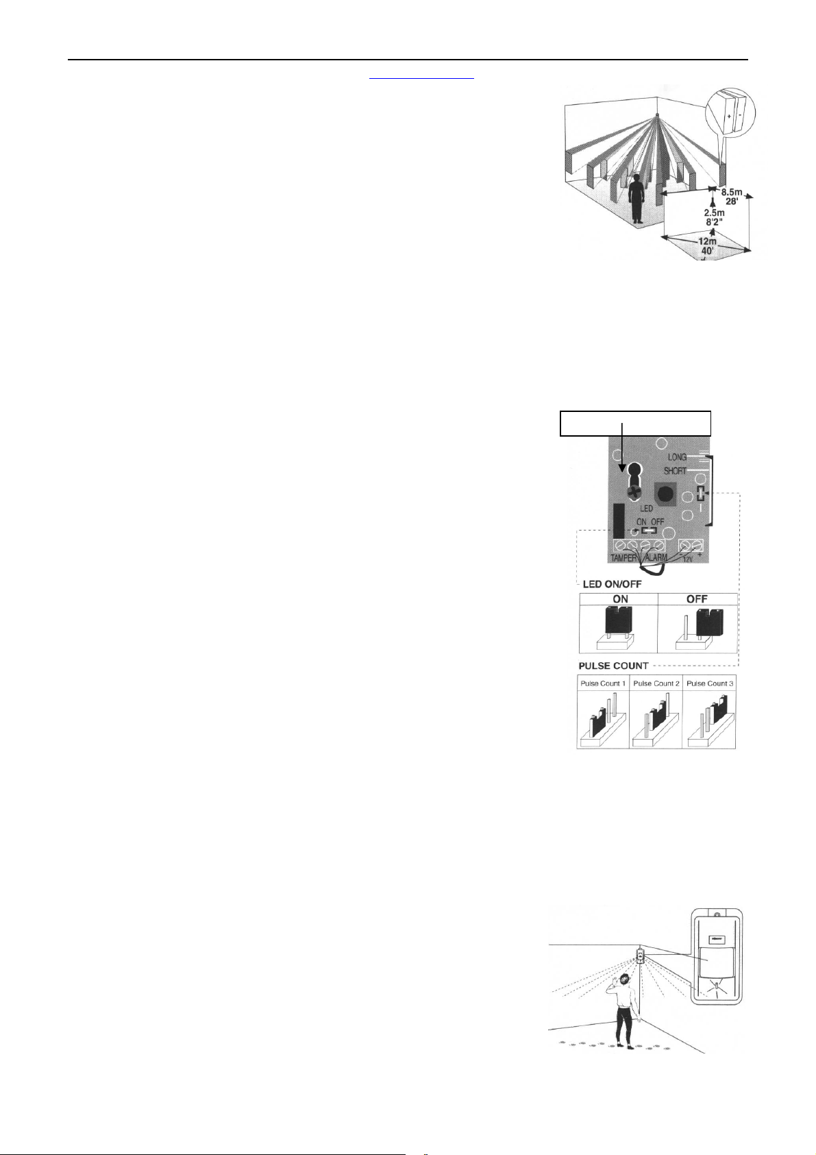
11. ACCESSORIES
Further accessories can be found on ourhomepage on www.easyalarm.ch.
11.1Motion / Presence detector-PIR-RJ45 (Plug&Protect)
11.1.1 Preliminary considerations
Choose the mounting location after careful consideration of the area to be protected.
The motion detector should be located so that an intruder will cross the infrared beam
pattern. If used to verify presence, a regular used room should be detected. Figure
shows the different infrared beam patterns at a typical mounting height of 2.5m.
Notes:
Do not mount detector towards direct sunlight or near to heat sources.
Do not mount detector behind items like glass or curtains because the infrared-
beam cannot penetrate them.
Keep away pets like cats or dogs from the protected area.
Do not protect the same area by more then one detector, because they can interfere.
11.1.2 Installation
Connect the cable of the motion detector on the EXT port of the alarm unit. The AC adapter of the alarm unit provides the
power supplyof the detector
11.1.3 Activation
Provided the motion detector is plugged in, EasyAlarm® detects the motion detector during the switching on procedure.
Important notes:
By disconnecting the motion detector during the operation mode, an alarm is
triggered followed by the announcement:”alarm due to sensor 1,sensor
failure!”
By connecting the motion detector after the start up procedure of the alarmunit,
an alarmis triggered followed bythe announcement:“alarm due to sensor 1,
sensor 1 activated!”
Mounting screw
11.1.4 Deactivation
If the motion detector is not plugged in, EasyAlarm® automatically deactivates the
supervision ofthe motion detector.
11.1.5 Specification
Supply voltage 9..16 VDC (through AC-adapter)
Dimension 107 x 58 x39 mm (Lx W x D) without swivel
Weight 75 g
Cable length 8m (RJ45)
Detection type passive infrared (PIR)
Alarm contact normally closed
11.1.6 Adjustment
Safety note:
Before you open cover please check, thatthe telephone cord is DISONNECTED.
Otherwise youcan get incontact with the telecommunication voltage!
Remove the front cover by twisting a flat screwdriver in the slot between the cover and
the base at the bottom of the motion detector
11.1.6.1 Pulse count
You can set PULSE jumper at position 1,2 or 3 corresponding to the desired pulse count before an alarm will be triggered.
Default = 2.
11.1.6.2 WALK-test
To disable LED indication, remove the LED jumper and place it on one pin only. To activate LED indication, place LED
jumper over both pins.
11.1.6.2.1 Mounting height
If motion detector is not mounted at 2.5m you can adjust like this:
5. Loosen the PC-Board holding screw. Slide the PC-Board so that the plastic
pointer on the right side is positioned at the appropriate scale position.
For higher than 2.5m => Slide PC-Board up
For lower than 2.5m => Slide PC-Board down
6. Tighten the PC-Board holding screw
7. Mount front cover
8. Walk through the entire protected area and observe the LED to ensure full
coverage
28
Page 29
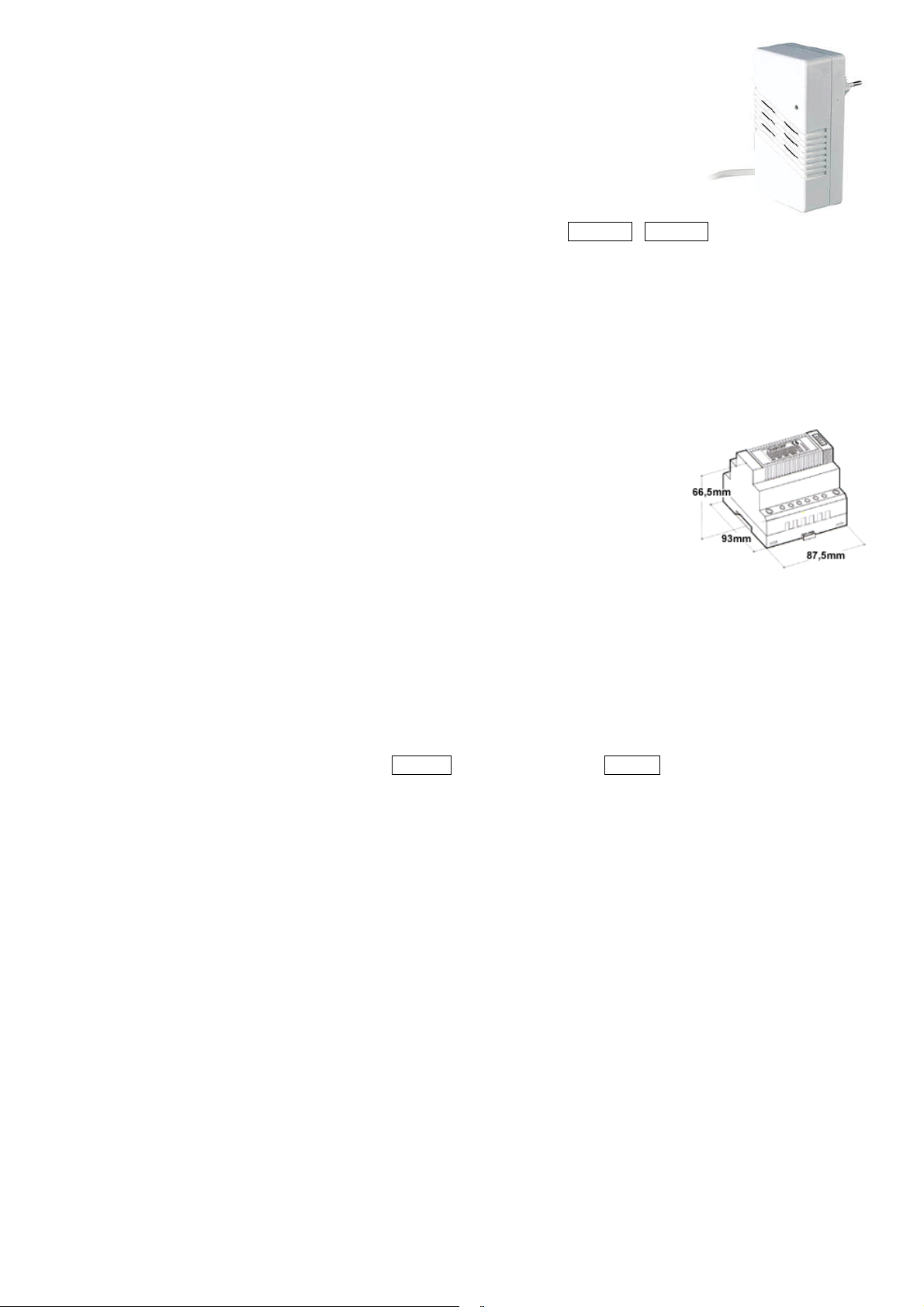
11.2 Siren EA-SIR-RJ45
Primary voltage 230 VAC / 50 Hz
Secondary voltage: 12 VDC 3 VA
Dimension: 120 x 65 x 77mm (L x W x H)
Weight: 200 g
Length of cable: 3 m
Installation: connect in place of the BBT-DC12S-RJ45 AC-adapter
Functions:
A) periodical ton of the siren (during inactive waiting period)
B) in case of an alarm in listening-in connection, the siren can be activated permanently
C) the siren can be switched on/off during phone connection by entering DTMF 6 / DTMF 4 .
11.3 230V-Switch EA-SWI-RJ45
Same as EA-SIR-RJ45, but instead of the siren a 230VAC load (f.e. a light) can be switched on/off during connection.
Output cable with Euro-jack-connector with maximum load of 2.5A.
Activation of output:
A) Output is activated automatically, as soon as analarm criteriais fulfilled (siren, floodlight)
B) Output is activated automatically, if an alarm remains unacknowledged (siren, floodlight)
C) Output is activated during phone connection by request (siren, floodlight)
11.4 DIN-Adapter interface EA-ACDC-SWI-RJ45
Primary voltage: 230 VAC / 50 Hz
Secondary voltage: 12 VDC / 150 mA (no load < 17.5 V)
Safety label: EN60950, 1992
Dimension: 52.5 x 93 x 68.5mm (L x W x H)
Weight: 250 g
Connection: Screw terminal
Relay output: max. 2A / 1000 VA (make contact)
Optocoupler input: 10..230 V (AC or DC) => sensor 1
Dimensions: 120 x 65 x 42 (L x W x H)
Cable: 3m (RJ45)
Weight: 500 g
Installation: connect in place of the BBT-DC12S-RJ45 AC-adapter
Activation of output:
A) Output is activated automatically, as soon as analarm criteriais fulfilled (siren, floodlight)
B) Output is activated automatically, if an alarm remains unacknowledged (siren, floodlight)
C) Output is activated during phone connection by request (siren, floodlight)
D) Operation as a remote-controlled system (remote switching ofheater, engines and so on)
E) many more applications are possible
Remote Switching procedure:activation ofoutput DTMF 6 / deactivation of output DTMF 4
29
Page 30

12. SPECIFICATIONS / WARRANTY
Changes to product and performance can be made at any time without announcement.
12.1 Specifications
12.1.1 Alarm unit EasyAlarm® EA-8-EXT
Supply voltage: 9..16 V DC (byAC adapter at EXT/≂ connector)
Backup: 9V-battery (typical duration of operation about 70 hours)
Current input: Supervision mode: 7 mA (typical) / during announcement: 55 mA (max.)
Announcement: Voice chip with four integrated languages: German, French, English, Italian
Other languages combinations onrequest
Material ofhousing: ABS
Dimensions: 200 x 110 x 31mm (L x W x H)
Weight: 320 g without the battery
Telephone cord: 8 m (country specific telephone plug on request)
Calling method: DTMF (Tone dialling)
12.2 AC-adapter BBT-DC12S-RJ45
Primary voltage: 100 – 240 V / 50 – 60 Hz
Secondary voltage: 12 VDC/ 6 VA
Safety label: EN60950, 1992
Dimension: 70 x 30 x 60 mm (L x W x H)
Weight: 102 g
Cord length: 3 m (RJ45)
12.3 Warranty
Dear customer
Each EasyAlarm® is manufactured and tested according to stringent quality rules. If the unlikelycase should occur, that
due to a manufacturing error the product is malfunctioning, Leitronic AG will guarantee in addition to your sales
distributor warranty of repairs without any labour or material costs for 2 years after date of purchase.
Warranty is only granted, if the unit has been used as described in the instruction manual.
Warranty will not be given under following circumstances:
If there is no invoice or receipt with date of purchase, vendor’s name and serial number.
These documents havebeen changed or modified.
If serial number on type label has been changed, cleared, removed or modified in any way.
If anyrepair, modification or other adaptation has been carried out byan unauthorized person or company.
Damage dueto tampering with device.
Damage dueto external influence (lightning, water, fire and soon).
Leitronic AG
Engeloostr. 16
CH-5621 Zufikon
Tel. +41 (0)56 648 4040
www.easyalarm.ch
Jippie’s Kindersicherheitsartikel
Antwortnummer 10'000
NL-5200 VE Hertogenbosch
Tel. +31 736 214 273
30
Page 31

13. INDEX
AC-adapter..........................................6, 8, 9, 28, 29, 30
Accessories........................................................2, 5, 28
Acoustical monitoring.....................5, 12, 16, 17, 23, 32
Alarm... 2, 3, 4, 5, 7, 9, 10, 11, 12, 13, 14, 17, 18, 20, 22,
23, 24, 27, 28, 30, 32
call........................................................................ 18
due to noise...............................13, 16, 17, 20, 21, 32
due to power failure....................................13, 17, 32
due to sensor ..............7, 10, 16, 17, 20, 22, 23, 28, 32
how to acknowledge.........................................18, 32
repetition......................................................2, 18, 24
unacknowledged........................16, 18, 19, 20, 21, 29
Announcement...3, 4, 7, 9, 14, 16, 17, 18, 19, 20, 21, 22,
23, 24, 25, 27, 28, 30, 32
individual message.................... 5, 7, 9, 10, 14, 18, 20
Language ................................................... 2, 7, 9, 14
Arm.......................................................................... 12
Battery........2, 3, 4, 5, 6, 8, 13, 16, 18, 20, 21, 22, 24, 30
check..................................................................2, 21
compartment.......................................... 4, 5, 6, 8, 21
replacement........................................................2, 21
Beep ..................................10, 11, 13, 15, 16, 20, 22, 24
Calling methode
tone-dialling.......................................................... 30
Calling number...2, 5, 6, 9, 13, 14, 16, 17, 18, 19, 20, 21,
22, 24, 26, 27, 32
dialling delay....................................................13, 25
how to program..................................................2, 13
Calling number sequence..2, 5, 14, 18, 20, 21, 22, 24, 27
how to program..................................................... 14
Check
battery................................................................2, 21
Check call..............................................................2, 19
dialling-in............................................. 18, 19, 22, 26
Commands
tone-dialling......................................3, 18, 19, 22, 32
Connection.2, 3, 4, 5, 6, 9, 10, 12, 14, 16, 17, 18, 19, 20,
22, 25, 26, 27, 29, 32
hands-free ..................5, 12, 13, 17, 18, 19, 20, 26, 32
volume.............................................................. 18
listening-in................................ 12, 18, 19, 25, 26, 29
time-out................................................ 14, 18, 19, 32
Contact-sensor ............................................. 3, 8, 13, 23
Cord.............................4, 5, 6, 7, 8, 9, 21, 22, 25, 28, 30
Default
setting...............................................2, 10, 18, 23, 24
value..........................................................17, 24, 32
Dialling delay.......................................................13, 25
Dialling-in................................................ 18, 19, 22, 26
ringing cycles...................................................19, 26
Disarm...................................................................... 12
DTMF... 14, 16, 18, 19, 20, 21, 23, 24, 25, 27, 29, 30, 32
Emergency
button................. 13, 16, 17, 18, 19, 20, 21, 23, 26, 32
call.............................3, 10, 11, 16, 17, 18, 20, 23, 32
Exchange.................................................................. 13
dialling delay....................................................13, 25
Factory setting.......................................2, 10, 18, 23, 24
Function switch... 5, 6, 7, 8, 9, 10, 11, 12, 13, 14, 15, 19,
21, 22, 23, 24
Hands-free..........5, 10, 11, 12, 13, 17, 18, 19, 20, 26, 32
Incoming call................................................... 2, 19, 26
Individual message........................ 5, 7, 9, 10, 14, 18, 20
how to record.....................................................2, 14
Installation................................................2, 6, 8, 28, 29
Key.5, 7, 9, 10, 11, 12, 13, 14, 15, 16, 17, 18, 19, 20, 26,
27, 32
LED....................... 5, 6, 7, 14, 16, 17, 18, 22, 23, 28, 32
Listening-in ........... 10, 11, 12, 17, 18, 19, 25, 26, 29, 32
Loudspeaker ..........................................................5, 20
Microphone .................................................................5
Mode...........................................................................3
listening-in................................ 12, 18, 19, 25, 26, 29
supervision...................2, 5, 16, 17, 18, 19, 21, 30, 32
waiting period.2, 14, 16, 17, 19, 20, 22, 23, 24, 29, 32
Monitoring. 2, 5, 8, 10, 11, 12, 13, 16, 17, 18, 19, 21, 23,
32
waiting period.2, 14, 16, 17, 19, 20, 22, 23, 24, 29, 32
Motion sensor.......................................2, 5, 6, 7, 16, 20
Noise.....................................4, 5, 12, 17, 18, 20, 23, 32
Pager .........................................................................18
PIN-code .......................................... 7, 9, 15, 19, 20, 22
Power failure ..........................................4, 5, 16, 17, 22
Pre warning period..................................... 2, 10, 17, 32
Presence verification... 2, 6, 8, 10, 16, 17, 18, 20, 22, 23,
28, 32
time-out .................................................................10
Program
alarm repetition............................................ 2, 18, 24
calling number ...................................................2, 13
calling number sequence.........................................14
lock program mode.................................................15
unlock program mode.............................................15
Pulse dialling .......................................................20, 22
Ringing cycles .....................................................19, 26
Safety instructions................................................2, 4, 6
Select user language....................................... 2, 7, 9, 14
Sensitivity....................................................................3
Sensitivity (noise)..................................................5, 12
Sensor
contact. 2, 3, 4, 5, 6, 7, 8, 9, 10, 11, 12, 13, 17, 20, 22,
23, 28, 29, 32
motion ..............................................2, 5, 6, 7, 16, 20
wired..............................................................3, 5, 21
Siren...............................................2, 10, 11, 12, 17, 29
Supervision
active mode.....................................16, 18, 20, 21, 32
inactive mode........................................16, 18, 21, 32
mode...................................................2, 5, 17, 30, 32
noise level..........................................................5, 12
Switch
function5, 6, 7, 8, 9, 10, 11, 12, 13, 14, 15, 19, 21, 22,
23, 24
selection............. 5, 7, 9, 10, 11, 12, 16, 20, 21, 22, 23
Telephone line .............................................................4
Test call.................................2, 5, 16, 18, 19, 20, 22, 27
Time-out.............................................10, 17, 18, 23, 32
Tone-dialling.............................. 2, 3, 18, 19, 20, 22, 32
commands.........................................3, 18, 19, 22, 32
Waiting period....2, 14, 16, 17, 19, 20, 22, 23, 24, 29, 32
31
Page 32
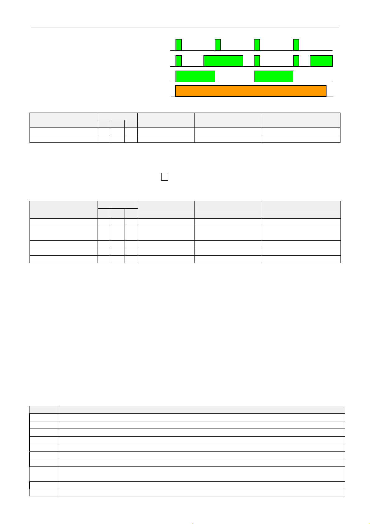
14. OVERVIEW
Noise
Nois
4 seconds
4 seconds
Telephone connection
Indicator (LED)
Supervision mode without acoustical monitoring
Supervision mode with acoustical monitoring
Supervision mode inactive
4 seconds 4 seconds
During phone connection
Alarm independent of alarm unit state (armed or disarmed)
1)
Cause of alarm
Emergency (Sensor-2)
Sensor-3
3)
1.) Default values without en without consideration ofuser specific programming in accordance to section 5
2.) Emergency call activation according to section 5.2.2: An emergency call will be triggered, if the button has been
activated for one second. After a pre alarm period of 20 seconds EasyAlarm®starts dialling calling number(s) and a
hands-free connection is established. During the pre warning period the alarm can be cancelled by pressing the
emergency button respectively by pressing key 0 .
3.) Sensor-3 activation according to 5.3.1.
I II III
2)
active on„Default value“
Entry-Delay Connection mode Announcement
Delayed Hands-free connection „Emergencycall activated“
Un-delayed Listening-in connection „Alarm dueto sensor 3“
Alarms only if alarm unit is armed
„Default value“
1)
Cause of alarm
Sensor 1
4)
Presence verification
Sensor 2
Noise (Babyphone)
6)
7)
Mains power loss
4.) Sensor-1 activation according to 5.1.1.
5.) Sensor-1 can be used to verify if a person is present ( section 5.1.2), i.e. an alarm will be triggered if no motion is
detected within 24h. Before starting the alarm there is a pre warning period often minutes. If activation is detected
(motion detected or emergency button pressed) within this period, the alarm is cancelled, otherwise EasyAlarm
establishes a hands-free connection
6.) Sensor-2 activation according to 5.2.
7.) Noise monitoring according to 5.4: To avoid false alarm while acoustical monitoring, close windows and try to
eliminate sources of noise.
8.) EasyAlarm®monitors mains voltage and triggers an alarm ifpower loss is longer than 10 to 20 minutes (=> time-out
according to section 10.4). During a pre warning period of 1 minute the following message is announced „Alarm due
to power failure“. After this period EasyAlarm® dials the programmed number and a hands-free connection is
established. If EasyAlarm® does not detect mains power during start up the monitoring remains inactive => „Power
failure“ is announced ! As soon as mains power is detected, EasyAlarm® starts to supervise mains power
I II III
5)
active on
Entry-Delay Connection mode Announcement
Un-delayed Listening-in connection „Alarm due to sensor 1“
10 Minutes/30
Seconds
Hands-free connection
“Alarm dueto presence
verification”
Un-delayed Listening-in connection „Alarm due to sensor 2“
Un-delayed Listening-in connection „Alarm due to noise“
1 Minute Hands-free connection „Alarm due to power failure “
®
Alarm release renewed
After an alarm EasyAlarm® remains inactive during a waiting period of two minutes. Only if at expiration of this
waiting period an alarm event occurs again, a new alarm is released. After an alarms through to sensor-1/2/3 a renewed
alerting comes offonly if to the alarm contact returned to the state of rest.
Tone-dialling commands
DTMF => Every valid command will be signalled
0 Terminate phone connection and acknowledge alarm
1 Switching to hands-free mode andrestart connection time-out
2 Repeat announcements (Individual message / Cause of alarm)
3 Restart connection time-out (2minutes)
4 Deactivate output (i.e. switching offalarm siren)
5 Announcement of current supervision mode as well as condition of the output
6 Activate output (i.e. switching on the alarm siren)
7 Change to inactive supervision mode (I, II, III)=> monitoring for noise, sensor-1, sensor-2, mains failure and
presence verification inactive. Emergency call and sensor-3 alarm are still possible.
8 Terminate phone connection without acknowledgment
9 Change to active supervision mode (I, II, III) => All monitoring functions re-activated
32
 Loading...