

Page 1
LEITRONIC AG
Swiss Security Systems
EasyAlarm ELEVATOR
Issue: 11 / 2014
Code: 0221Code: 0221
Isue: 2/2019
Page 2
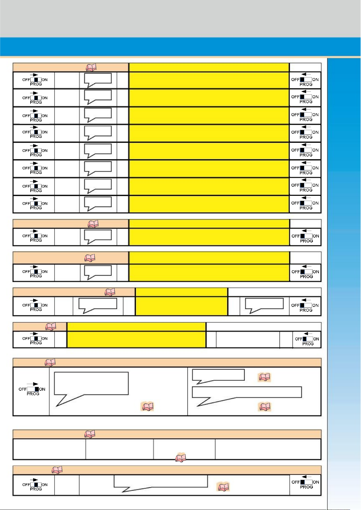
Program calling numbers 5.1 Write down numbers
**1 Announcement *
**2 Announcement *
**3 Announcement *
**4 Announcement *
**5 Announcement *
**6 Announcement *
**7 Announcement *
**8 Announcement *
Calling number sequence 5.2.2 Write down sequence
**0 Announcement *
Program routine number 6.5.5 / 6.5.4 Write down number
**9 Announcement *
Record individual announcement 5.4 Write down text
**# Indiv. Announcement * Indiv. Announcement
PIN-Code 5.5 Identification (4 to 7 digits)
# # re-enter PIN-Code #
Operation 6
Battery error Emerg. Call activated 9.12
Check phone line
Power failure (Operation)-supervision 1/2/3 activated
4.8 4.8
Test calling numbers 1-9 6.8
Press key 1-9 Selected number will be Check hands-free Disconnect: called party must
connection quality press 0
3.2
Check wiring 4.6
**** 1/2/3 activated / desactivated 4.6
Start-up
Page 3

1. Safety instructions...................................................................................................................................................................................... 2
1.1 Telephone connection.......................................................................................................................................................................... 2
1.2 Power supply....................................................................................................................................................................................... 2
1.3 Safety notes......................................................................................................................................................................................... 2
2. Set view........................................................................................................................................................................................................ 3
2.1 Sub-communication unit.......................................................................................................................................................................4
3. Assembly...................................................................................................................................................................................................... 5
3.1 Assembly / drilling template for EasyAlarm®........................................................................................................................................ 5
3.2 Assembly of the sub-communication unit.............................................................................................................................................5
4. Installation.................................................................................................................................................................................................... 7
4.1 Telephone wiring ................................................................................................................................................................................. 7
4.2 Sensor-Wiring...................................................................................................................................................................................... 7
4.3 Power supply....................................................................................................................................................................................... 9
4.4 Outputs ............................................................................................................................................................................................... 9
4.5 LMK70T-Amplifier (Hearing aid loop / Exciter)......................................................................................................................................9
4.6 Check wiring (Functional test).............................................................................................................................................................. 9
4.7 Programming....................................................................................................................................................................................... 9
4.8 Operation............................................................................................................................................................................................. 9
5. Programming............................................................................................................................................................................................. 10
5.1 How to program new calling numbers (Announce/Change/Delete)....................................................................................................10
5.2 Calling numbers sequence................................................................................................................................................................. 11
5.3 Remote programming of calling number and calling number sequence.............................................................................................11
5.4 How to select user language / record individual message..................................................................................................................12
5.5 How to program PIN-Code (Identification)..........................................................................................................................................12
6. Functional description.............................................................................................................................................................................. 13
6.1 Self test at power on.......................................................................................................................................................................... 13
6.2 Arm / Disarm system.......................................................................................................................................................................... 13
6.3 Waiting period.................................................................................................................................................................................... 13
6.4 Supervision mode.............................................................................................................................................................................. 13
6.5 Alarm functions.................................................................................................................................................................................. 14
6.6 Telephone connection........................................................................................................................................................................ 15
6.7 Alarm repetition..................................................................................................................................................................................16
6.8 Test call.............................................................................................................................................................................................. 16
6.9 Remote access by dialling-in.............................................................................................................................................................. 17
6.10 Machine room communication (EA-8-DPXM / EA-8-DPXFM)............................................................................................................18
6.11 Fire brigade communication EN81-72................................................................................................................................................19
7. Useful notes............................................................................................................................................................................................... 20
7.1 Touch-tone commands....................................................................................................................................................................... 20
7.2 Announcement...................................................................................................................................................................................20
7.3 Functional tests..................................................................................................................................................................................21
7.4 Battery check / replacement ..............................................................................................................................................................21
7.5 Maintenance...................................................................................................................................................................................... 21
8. Trouble shooting / Error handling............................................................................................................................................................ 22
8.1 General.............................................................................................................................................................................................. 22
8.2 Telephone line / Connection .............................................................................................................................................................. 22
8.3 Quality of the hands-free communication / Touch-tone during connection..........................................................................................23
8.4 Dialling-in........................................................................................................................................................................................... 23
8.5 Wiring test.......................................................................................................................................................................................... 24
9. Special programming................................................................................................................................................................................ 25
9.1 Ready/Modify profile.......................................................................................................................................................................... 25
9.2 Factory settings (Default Value)......................................................................................................................................................... 25
9.3 Alarm repetitions................................................................................................................................................................................ 25
9.4 Routine call intervall...........................................................................................................................................................................25
9.5 Power failure...................................................................................................................................................................................... 25
9.6 User announcement .......................................................................................................................................................................... 26
9.7 Connection time-outs......................................................................................................................................................................... 26
9.8 Dialling-in (remote access).................................................................................................................................................................26
9.9 Remote programming........................................................................................................................................................................ 27
9.10 Dialling delay for EA-8-DPXN............................................................................................................................................................. 27
9.11 Sensor-1: Misuse-protection..............................................................................................................................................................27
9.12 Sensor-2: Emergency-button.............................................................................................................................................................28
9.13 Sensor-3: Technical alarm..................................................................................................................................................................28
9.14 Control sub-communication unit ........................................................................................................................................................29
9.15 Background-Noise filter...................................................................................................................................................................... 29
9.16 Hands-free volume adjustment..........................................................................................................................................................29
9.17 DTMF optimization for mobile connections......................................................................................................................................... 29
10. Accessory................................................................................................................................................................................................... 30
11. Contents of delivery / Specification......................................................................................................................................................... 33
11.1 Contents of delivery........................................................................................................................................................................... 33
11.2 Specification....................................................................................................................................................................................... 33
12. Warranty..................................................................................................................................................................................................... 34
13. Drilling pattern........................................................................................................................................................................................... 35
14. Index........................................................................................................................................................................................................... 36
1
Page 4

1. SAFETY INSTRUCTIONS
1.1 Telephone connection
EasyAlarm® is designed to connect to an analogue telephone line. This network must remain in service for at least one
hour after a mains power loss according to EN81-28.
These are:
analogue PSTN (with EA-8-DPXN in combined use with downstream existing subscriber as modem/fax).
analogue port of an ISDN terminal:
ISDN-NT has to be reprogrammed for emergency operation at the ab-port.
One line must be available at any time.
Mobile interface / Gateway with approval, i.e. from Leitronic 10.7.1.
analogue port of a private exchange using UPS (Interruptible power supply 1h buffering).
DECT-Interface 10.7.2.
Multiple EasyAlarm® sharing one line:
Ensure that the first alarm number is always available, because if multiple alarms triggered at the same time it is
possible that only first number can be reached.
A maximum of three units can share one line.
In case of star cable routing (max. 15 Ω difference per connection = Calc 2 x conductor resistance!) up to 4 diallers can
be connected. Example: AWG 24 (U72) = 2 x 90 Ω / km => difference in length max. 15 Ω / (2 x 90 Ω / km) = 0.083km.
In case of a two-step-dialling-in 6.9.2 the number of diallers is doubled.
Not suitable:
VoIP (VoiceoverInternetProtocol), cable-TV-modem or NGN (NextGenerationNetwork), as in case of a power loss even
with local backup the network (Amplifiers, Fiber network etc.) cannot guarantee EN81-28.
If a "fail-safe" connection is guaranteed, ensure that DTMF-transmission will be real-time i.e. configure “DTMF
inband” on the ATA (AnalogTelephoneAdapter).
The voltage of the telephone network is defined in EN 41003. It is higher than 40 V and therefore please beware for
electrical hazard and disconnect the phone line whenever working on connections.
The telephone line can be protected with a lightning protection interface 10.11.
1.2 Power supply
A transformer according to the safety regulation EN60950 provides power supply. 9V battery is used as a back up in case of
power failure. It is located on the rear side oft the device.
In case of a mains power loss in combination with a low battery, EasyAlarm® can still make a call to one destination
powered over the telephone line.
If a relay is used to start emergency call, beware that this relay is powered for at least 1 hour after a mains loss.
1.3 Safety notes
All the electrical connections have to be potential free; therefore no ground connection between elevator control-unit
nor the power supply is permitted. Observe the regulation according to EN60950.
If you hear or o after power on, you have to replace the battery 7.4.
Check alarm functions and start a test-call, before the system is put in service 6.8.
Please note, an alarm by telephone is only successful if the subscriber takes care of the following points:
Alarm must not be answered by an answering machine or equal equipment.
Mobile phones can be out of coverage (e.g. underground car park, shielded rooms, remote areas and so on).
Do not open the device (exception: opening of battery compartment).
Do not bring the device into contact with water.
Use only small signal switches or relay contacts for the emergency buttons. Do not use 230 V contact material, since it
may not give a reliable contact.
2
Battery failure
beep,beep,beep
Page 5
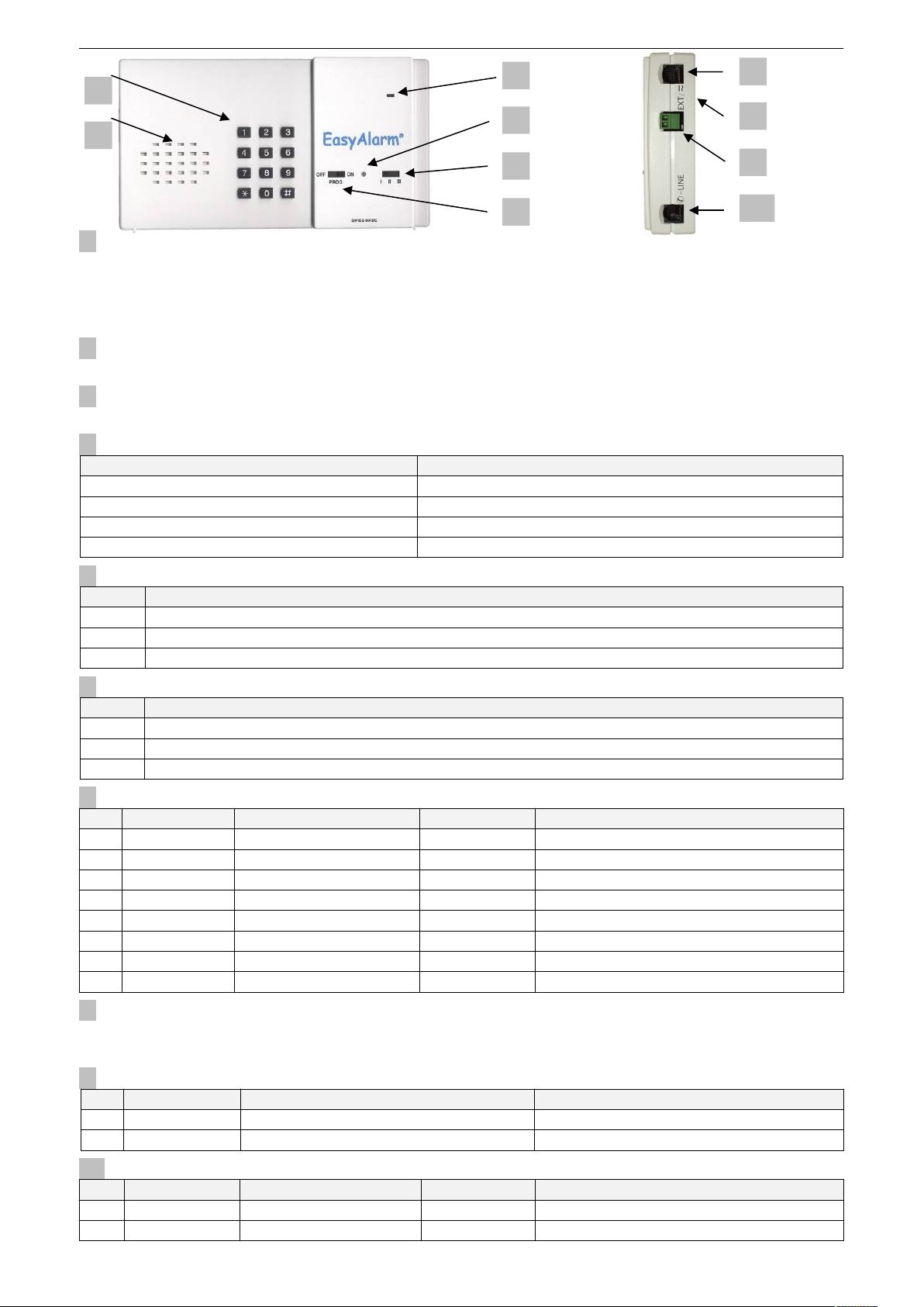
2. SET VIEW
1. Keypad
Is used to program 5 and to control the alarm unit 6.
All the EasyAlarm®-keys are marked in black within this document: 123456789*0#.
In contrast the touch-tone commands initiated on the telephone to remote control the alarm unit are marked in white:
123456789*0#.
2. Speaker
Serves to guide the user during programming or during telephone connection as a speaker.
3. Microphone
The microphone is turned on during the hands-free connection.
4. Indicator (LED)
Status of the LED's Operation mode
Green Waiting period 6.3
Green flashing every 4 seconds Supervision mode (active) 6.4
Green is on and off for 4 seconds alternatively Supervision mode (inactive) 6.4
Orange Telephone connection 6.6
5. Selection switch
Position Info
I Emergency call without misuse protection / Signal S1 (Sensor-1) not monitored
II Emergency call without misuse protection / Signal S1 (Sensor-1) as alarm: adapt alarm condition 9.11.1
III Emergency call with misuse protection / Signal S1 (Sensor-1) used for misuse filter 9.11.2
6. Function switch
Position Info
OFF Device is switched off
PROG Entering of calling numbers, calling number sequence, PIN-Code and further parameters
ON Device is in supervision mode
7. External port (EXT) for sub-communication unit, emergency button etc.
PIN Info Function Colour Specification
1 LS+ Speaker blue On -potential, observe isolation
2 OUT Switch orange On -potential, observe isolation
3 S2 (Sensor-2) Emergency contact (EC) black On -potential, observe isolation
4 +12 V Supply red On -potential, observe isolation
5 S1 (Sensor-1) Door signal green On -potential, observe isolation
6 GND GND yellow On -potential, observe isolation
7 S3 (Sensor-3) Alarm contact brown On -potential, observe isolation
8 MIC+ Microphone white On -potential, observe isolation
8. Battery compartment
The 9 V-battery is used to supply power during a power failure. Change battery 7.4.
In the battery compartment is a switch to configure the type of the emergency button (NO / NC) 9.12.
9. Plug S1
PIN Info Function Specification
1 S1a Misuse-protection signal 10 to 50 V AC/DC
2 S1b Misuse-protection signal 10 to 50 V AC/DC
10. Phone-jack (-LINE)
PIN Info Function Colour Specification
3,4 a,b-IN to PSTN / Gateway red, green On -potential, observe isolation
2,5 a/b-OUT to phone/modem black, yellow On -potential, observe isolation
EA-8-DPXN, EA-8-DPXM and EA-8-DPXFM only
3
4
6
3
2
1
5
7
8
9
10
Page 6
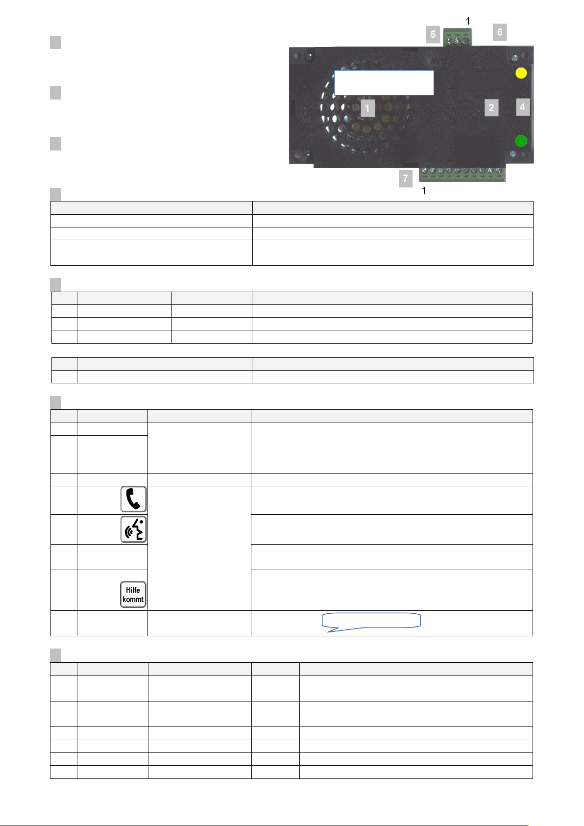
2.1 Sub-communication unit
1. Speaker
Serves to guide the user during programming or during the
telephone connection as a speaker.
2. Microphone
The microphone is turned on during the hands-free
connection.
3. Volume on the back side!
To adjust volume of the internal speaker (LMK70C)
or Loop-output (LMK70T).
4. LED-Indicators
With light-pipes PGN25145 to front panel Operation mode
Yellow Call activated
Green Hands-free communication
EN81-28:2018 alternating blinking (since version
8.51)
Nou routinecall during the last intervall 9.4
5. Port X2
PIN LMK70C/T LMC70 Specification
1 NO (normally open) EC On -potential, observe isolation
2 C EC On -potential, observe isolation
3 NC (normally closed) - On -potential, observe isolation
PIN LMK70T hearing aid loop / Exicter
4,5 Loop On -potential, observe isolation
6. Port X7
PIN Info Function Specification
1 VIN(-) 8 to 35 V DC
Max. 400 mA (12 V)
Max. 220 mA (24 V)
Supply i.e. from emergency light
Standby DPX, DPXF, DPXN: 70 mA (12 V) / 40 mA (24 V)
Standby DPXM, DPXFM: 95 mA (12 V) / 55 mA (24 V)
2,3 VIN(+)
decoupled via
diodes
5 Lamp(+) 8 to 35 V DC for Lamp1 and Lamp2
4 Lamp1(-) Open-Collector-outputs
(- is switching contact)
max. 300 mA/output
1.1A in total (fused)
Output-voltage=VIN
Yellow icon light (phone) indicates a telephone connection.
6 Lamp2(-) Green icon light (speak) is on, when hands-free connection is
established after receiving touch-tone command 1.
7 ECTest(-) Open PCB-switch INT in case of using en external remote controlled
emergency button.
8 LMK-OUT(-) Multifunctional output: Variants of use 9.14.2
a) to forward alarm to building control system
b) "Help is coming"-lamp
9,10 S3 (IN) Optocoupler-input
10 to 50 V (AC/DC)
Technical Alarm:
7. External port (EXT) for EasyAlarm®
PIN Info Function Colour Specification
1 LS+ Speaker blue On -potential, observe isolation
2 OUT Switch orange On -potential, observe isolation
3 S2 (Sensor-2) Emergency contact (EC) black On -potential, observe isolation
4 +12 V Supply red On -potential, observe isolation
5 S1 (Sensor-1) Door signal green On -potential, observe isolation
6 GND GND yellow On -potential, observe isolation
7 S3 (Sensor-3) Alarm contact brown On -potential, observe isolation
8 MIC+ Microphone white On -potential, observe isolation
4
Alarm due to Sensor-3
nur EA-LMK70C/T
LMK70C/T only
Page 7

3. ASSEMBLY
3.1 Assembly / drilling template for EasyAlarm®
Drilling template 13
Note:
If EasyAlarm® is mounted in a closed box (i.e. EA-IP-Box 10.10) the internal microphone must be turned off
(to eliminate acoustical feedback). In this case mark dialler to pointing out that the microphone is turned off. Label unit
with “microphone deactivated”.
3.2 Assembly of the sub-communication unit
Once mounted, the speaker and the microphone in particular should not be covered, otherwise the communication
quality decreases (reduced volume, poor hands free quality) 8.3.
Make sure the microphone hole and the panel hole fit.
The sub-communication unit must be mounted directly behind the panel without any gap, otherwise there will be an
acoustic feedback. If necessary insulate speaker and microphone room acoustically using foam or rubber.
Do not use any foil between the front panel and sub-unit, not even in waterproof versions option: -WG.
3.2.1 Retrofit solutions to existing elevators
3.2.1.1 Chrome panels (flush / surface mount, Inox=steel or PC=polycarbonate
EA-TAB (without button) EA-TAB-NT EA-TAB-HK("Help is coming") EA-TABPC-NTI (comm. unit
if current button remains in use incl. ext..button RT-42/Typ IX incl. ext. display RA-42 with integrated emerg. button)
Art. No: 100.0220 Inox 2mm Art. No: 100.0221 Inox 2mm Art. No: 100.0222 Inox 2mm
Art. No: 100.0210 PC 3mm Art. No: 100.0211 PC 3mm Art. No: 100.0212 PC 3mm Art. No: 100.0216 PC 3mm
100 x 200 mm 100 x 200 mm 100 x 200 mm 100 x 200 mm
3.2.1.2 Transparent frame for surface mounting of panels
Suitable for front panels 100.0220 to 100.0223 incl. two inlays on bottom / top for LED emergency light chain e.g. Art. No:
100.0870 or 100.0873 10.6
Art. No: 100.0231 Art. No: 100.0232 Seal
100 x 220 x 23 mm 100 x 200 mm (Foam 1.5mm)
incl. two mounting-screws for panels 100.0220 to 100.0223
5
Sub-comm. unit
Panel
Sub-comm. unit
Sub-comm. unit
Sub-comm. unit
Page 8
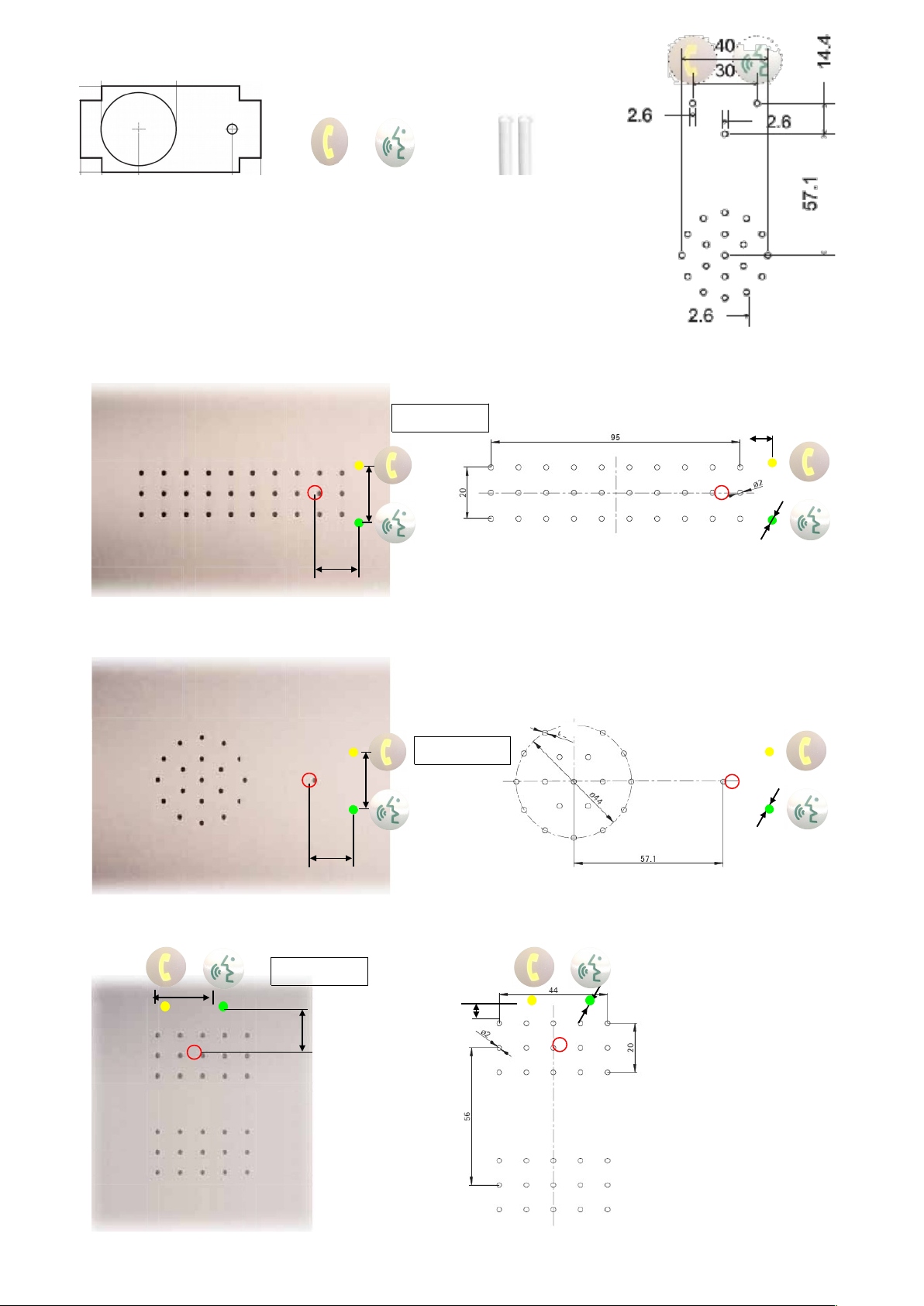
3.2.1.3 Panel drilling template with SNEL-retrofit kit (Art. No: 100.0277) Adhesive film for easy mount EN70-Symbols to stick on Light pipes
sub-communication unit panel front PGN25145
3.2.2 New installation or new panels
Drilling hole proposals from Schäfer GmbH with the appropriate order code.
In addition, two external EN81-70 indicators: e.g. Type MA42 (shepherds) or similar.
The built-in LEDs and two light pipes (Art. No: 25 145 PGN) will lead light to the
front: hole diameter Ø = 2.6-0.05mm.
Option 1: "G9924"
Option 2: "G9924 LMK70-LED" with holes for light pipes and engraving
Option 1: "G9924wg" waterproof drilling pattern => use EA-LMK70C-WG to achieve IP54
Option 2: "G9924wg LMK70-LED" with holes for light pipes and engraving
Option 1: "G4824"
Option 2: " G4824 LMK70-LED" with holes for light pipes and engraving
6
14.4
Ø2.6
30
14.4
14.4
30
4.4
Ø4
Ø2.6
Ø2.6Ø4Ø4
Page 9
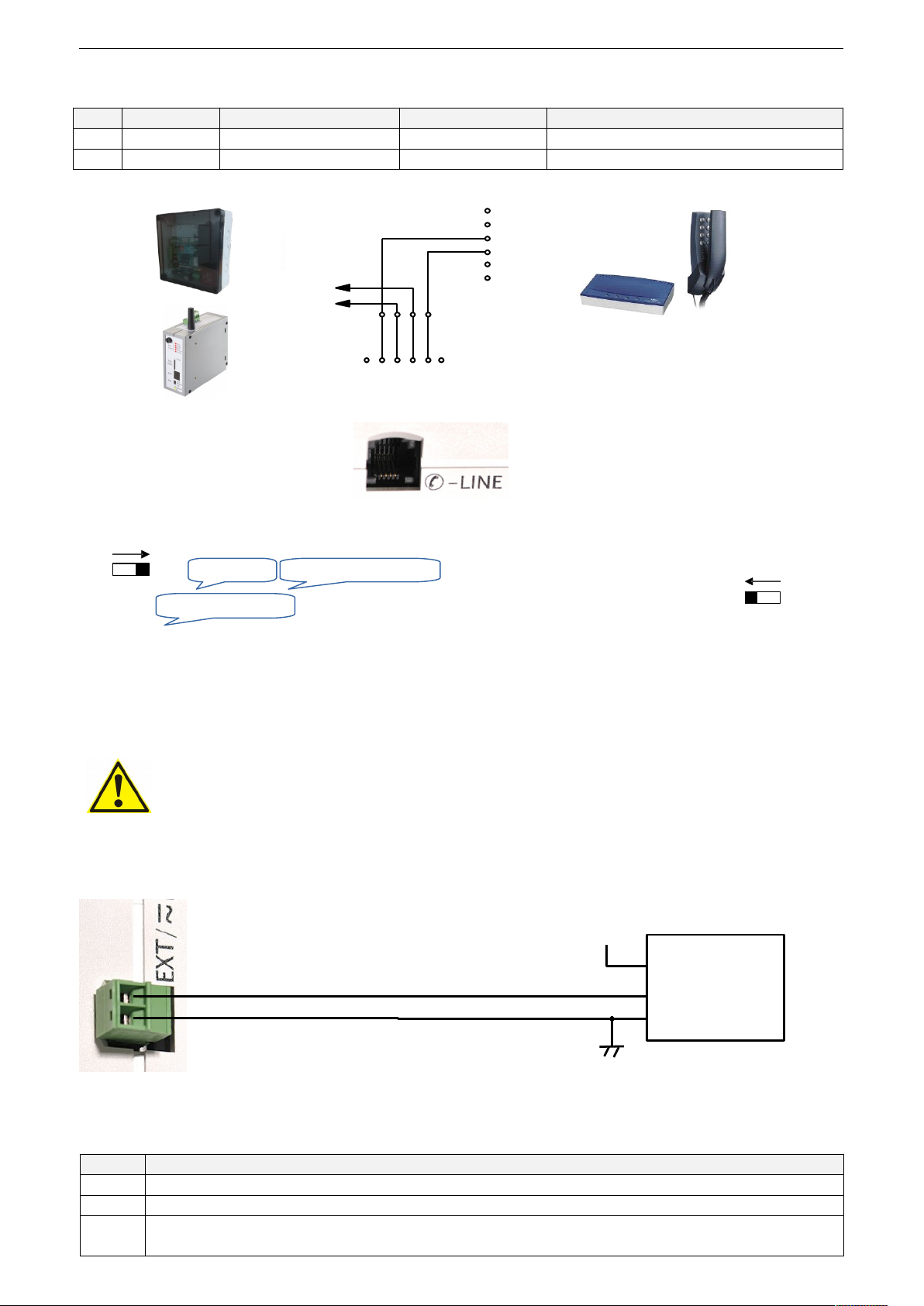
4. INSTALLATION
Place 9 V-battery or voltage converter EA-DCDC ( 10.3.1) inside the battery compartment on the back side of the unit.
4.1 Telephone wiring
PIN Info Function Colour Specification
3,4 a,b-IN to PSTN / Gateway red, green On -potential, observe isolation
2,5 a/b-OUT to phone/modem black, yellow On -potential, observe isolation
EA-8-DPXN, EA-8-DPXM and EA-8-DPXFM only
4.1.1 Check telephone line
In case of check if voltage over the a,b-IN wires is between 20-50 V DC.
4.2 Sensor-Wiring
All sensor-inputs are available for potential-free contacts on the EXT jack on the alarm unit. Sensor-1/3 are also available
as voltage input => built-in optocoupler (S1 at EasyAlarm® S3 at the LMK70C/T). The non-insulated connections are
sensitive to radiation from external fields, and connected to the PSTN (telephone network). Thus the quality of the handsfree connection is optimal, consider the following points:
Cut cable to size and do not wind up together with other cables.
Line up cable separated from cable in parallel to avoid interference. Do not extend wiring over the
hanging cable.
Disconnect telephone line before connecting sensors to avoid contact to the telephone voltage.
All sensor-contacts connected directly must be potential free.
Provide isolation of at least 1750V to ground.
Hands-free problem solving 8.3.
4.2.1 Misuse protection input / Alarm signal S1 (Sensor- 1)
Connect door / photocell signal S1 (10 to 50 V AC or DC) to the green terminal of the on the EasyAlarm®. Polarity and
reference potential may be arbitrary.
Function depends on the position of the selection switch
Position Info
I Emergency call without misuse protection / Signal S1 (Sensor-1) not monitored
II Emergency call without misuse protection / Signal S1 (Sensor-1) as alarm: adapt alarm condition 9.11.1
III Emergency call with misuse protection / Signal S1 (Sensor-1) used for misuse filter 9.11.2
Emergency call will be stopped when signal changes within misuse-protection time-out (=travel time)
7
Door control/
Photocell
+
Polarity / potential unlimited
OFF
ON
PROG
Power failure
OFF
ON
PROG
Check phone line
Supervision x activated
1 2 3 4 5 6
Hanging cable
DPX: 2 wire
DPXN/DPXM: 4 wire
PSTN
GSM
MR-
Modem
Black
Red
Green
Yellow
1
2 Black
3 Red
4 Green
5 Yellow
6
EasyAlarm
PSTN
Gateway
Page 10
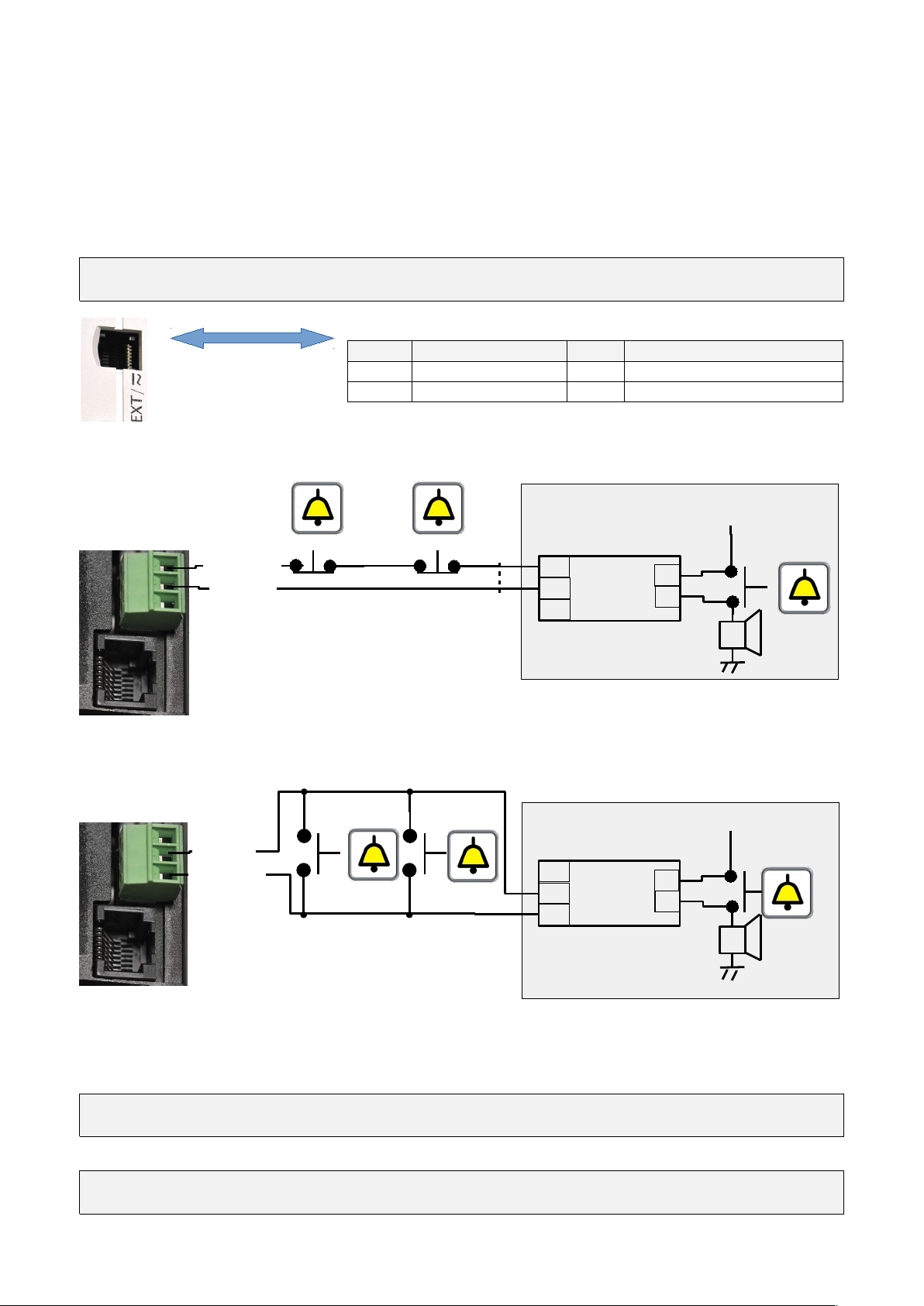
4.2.2 Potential free emergency button (Sensor-2)
The emergency call button can be connected directly to the EXT jack or to the X2 plug on the sub-communication unit.
Requirements for an emergency call button according to EN81-70:
Symbol: Bell sublime.
Centre of the button >90cm (<110cm) from cabin floor.
Surface ≥ 490mm2.
Panel orientation is portrait: alarm button must be the first button from the bottom.
Panel orientation is landscape: alarm button must be the first button from the left.
Use only small signal switches or relay contacts. Do not use 230 V contact material, since it may not give a reliable contact.
If the emergency button is not isolated, i.e. older panels with only a single alarm contact for the alarm horn, the accessory
EA-NT-IN ( 10.7) can be used to ensure isolation.
PIN Function Colour Specification
3 Emerg contact (EC) black On -potential, beware isolation
6 GND yellow On -potential, beware isolation
Wiring for normally closed contacts NC-contact Caution: In case of horn supply loss: Emerg. call
connect to X2 of sub-comm.-unit
or EXT-jack PIN 3/6
Wiring for normally open contacts: NO-contact
connect to X2 of sub-comm.-unit
or EXT-jack PIN 3/6
Adjust EasyAlarm® to the type of contact to be used (Normally open / Normally closed). Shipping: normally open,
configuration: 9.12.
4.2.2.1 Remote controlled emergency button
EA-LMK70C/T: if a remote-controlled button is used open drill hole INT inside the housing and connect
coil wires to X7: Lamp(+) and ECTest(-) (max. 300 mA/Open-Collector).
4.2.3 Alarm signal S3 (Sensor-3)
EA-LMK70C/T: Connect signal S3 (10 to 50 V AC or DC) to X7: S3 (IN). The polarity and the reference potential may
be arbitrary. Adapt alarm condition 19.13.
8
NO/EC
C/EC
EA-NT-IN
NC
NO
-
C
+
-
NC/EC
C/EC
+
EA-NT-IN
NC
NO
-
NC
C
+
-
+
RJ45-cable
2-wire / max. 3 m
Art. No: 118.0140
Retrofitting of existing plants with
single-contact button for the alarm horn
use EA-NT-IN ( 10.4)
Page 11
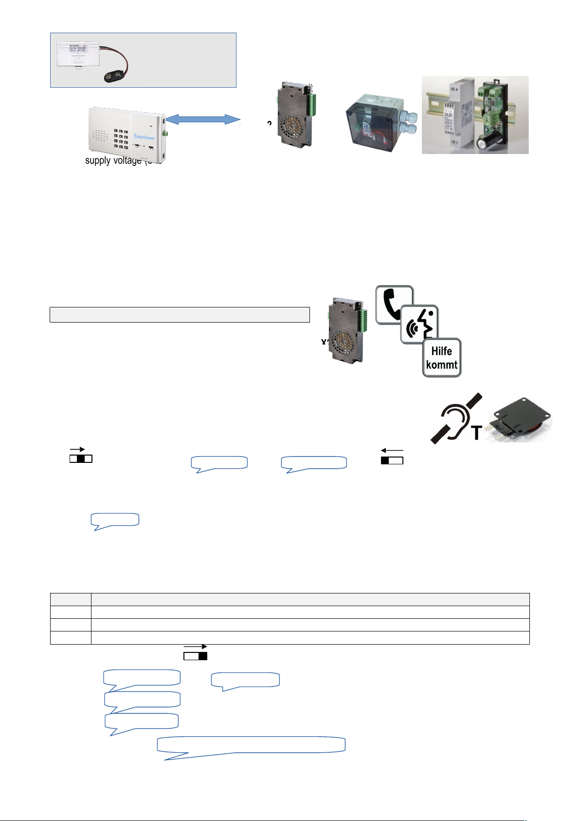
4.3 Power supply
Connect supply voltage (8 to 35 V DC) to X7: VIN(+) and VIN(-) of the sub-communication unit or to the voltage converter
EA-DCDC 10.3.1(Check polarity).
Notes:
These outputs need VIN to be functional: Lamp1, Lamp2, LMK-OUT, EC-TEST, Loop
The two VIN(+)-inputs of the sub-communication unit are decoupled via diodes.
e.g. for 24 V supply voltage (normal operation) and 12 V emergency power (UPS)!
If only 230V AC are available you may use uninterrupted power supply USV-230VAC-12V-IP 10.3.5:
EA-ACDC-USV 10.3.2 + EA-NSG 10.3.4 + 12V-battery pre-mounted in IP65 protective housing.
4.4 Outputs
Connect lamp phone to X7: Lamp(+) and Lamp1(-)
Connect lamp speak to X7: Lamp(+) and Lamp2(-)
EA-LMK70C/T: Relay/Lamp to X7: Lamp(+) and LMK-OUT(-)
Notes:
Output-voltage=VIN.
Current: max. 300 mA/Open-Collector.
Adapt output conditions to your needs 9.14.
4.5 LMK70T-Amplifier (Hearing aid loop / Exciter)
Connect either the hearing loop or the exciter at the output loop (terminal X2) and adjust amplifier
using potentiometer VOLUME. Not functional without VIN applied.
4.6 Check wiring (Functional test)
**** or
<n> = 1, 2 or 3 1: Sensor-1 = Misuse signal or alarm signal input S1
2: Sensor-2 = Emergency button contact
3: Sensor-3 = Alarm signal S3
In case of when emergency contact is idle adapt contact type 9.12.
4.7 Programming
Calling numbers, Identification and functional-parameter 5 and 9.
4.8 Operation
Choose selection switch position
Position Info
I Emergency call without misuse protection / Signal S1 (Sensor-1) not monitored
II Emergency call without misuse protection / Signal S1 (Sensor-1) as alarm: adapt alarm condition 9.11.1
III Emergency call with misuse protection / Signal S1 (Sensor-1) used for misuse filter
Set function switch to ON
In case of or 7.4.
In case of 8.2.
In case of 4.3.
After the announcement: EasyAlarm® is ready 6.
If you press key 1 - 9 a call to the appropriated calling number will be triggered.
Brief the alarm operator how to serve the EasyAlarm® call (short instructions available).
9
OFF
ON
PROG
Check phone line
Battery error
Power failure
(Operation mode-) Supervision I/II/III activated
2 aktivated
<n> deactivated
<n> activated
OFF
ON
PROG
OFF
ON
PROG
beep,beep,beep
Operation WITHOUT
sub-communication unit
using EA-DCDC 10.3.1
Operation WITH
sub-communication
unit
Supply voltage 230 V AC
USV-230VAC-12V-IP 10.3.5
EA-ACDC-USV 10.3.2
Page 12

5. PROGRAMMING
All the programmed parameters remain stored by switching off the alarm unit.
If you want to prevent EasyAlarm® from unwanted reprogramming 5.5.1.
Doing so you will get message when switched to PROG.
Adjusting this parameter has influence on the described performance. Change these values only when absolutely
necessary and test the desired behaviour prior to use.
5.1 How to program new calling numbers (Announce/Change/Delete)
EasyAlarm® supports nine calling numbers. To announce or modify a number please proceed as follows:
1. Set function switch to PROG.
2. Enter ** <n> (n =1 to 9: selected calling number).
3. If you want to modify calling number press *, otherwise proceed with step 5.
4. Enter new calling number. To delete number switch to OFF directly.
5. Set function switch to OFF.
Notes:
Check each phone number with a test call 6.8.
Each key press is confirmed with a beep.
Key # will lead to a dialling delay of 5 seconds, provided it is entered between two digits, e.g. a delay is essential in a
private exchange. (i.e. 0#calling number).
If your private exchange needs a flash pulse to start an internal call, following programming is possible: 2#
followed by the extension number.
Key * as part of the calling number will result in a call using protocol Point-ID/Contact-ID 5.1.1.
Calling number 1 cannot be deleted due to safety aspects because it is the only number to be called in case of an
emergency operation (supply power loss and battery empty at the same time).
Calling number 9 is reserved for routine call 6.5.5 and for alarm due to power failure 6.5.4.
5.1.1 Alarm using Point-ID (Contact-ID) protocol
If the alarm should be transferred to an alarm organisation using the Point-ID (Contact-ID) protocol, the alarm number has
to be followed by key * and the customer-ID. EasyAlarm® forwards the protocol to this alarm number and connects
hereafter to the following calling number in standard Hands-free connection mode.
Example:
Calling number 1: Number for Voice-call (without power supply this is the only number that can be called)
Calling number 2 and 9 (Point-ID) :074567890 Separator Customer ID: 3456
074567890 * 3456
Change calling number sequence **0 to 213, so that calling number 2 is called first!
Note:
The first character * that follows the alarm number will not be transmitted (=> separator). The customer ID is a four
digit code. In case of an alarm the following codes are transmitted according to the <Cause of alarm>.
213
Code <Cause of alarm> Zone
120 Alarm due to emergency button (Sensor-2) 902
140 Alarm due to Sensor-1 (Sensor-3) 901 (903)
301 Alarm due to supply power loss 900
601 Test call 900
602 Routine call 900
5.1.2 Hotline mode
You can use EasyAlarm® in a so called hotline-mode. EasyAlarm® only takes the telephone line and the private exchange
does the dialling (Program calling number 1 with #).
Using this Hotline-Mode the following programming are typical:
1. No user announcements during connection 9.6.
2. Dialling-in in Hands-free connection without PIN-Code 9.8.3.
10
Programming deactivated: PIN
to modify press *
...
Page 13
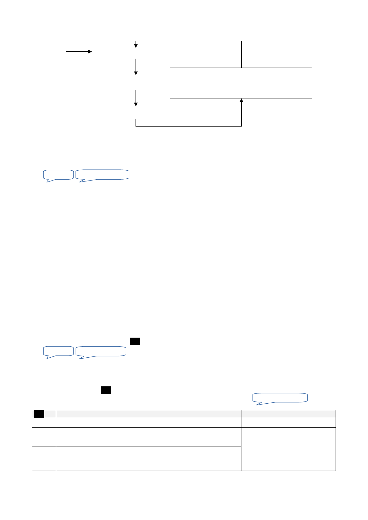
5.2 Calling numbers sequence
5.2.1 Standard-sequence
Alarm Calling number 1
if first party does not acknowledge
Calling number 2
if second party does not acknowledge
Calling number 3
A called party can acknowledge the alarm by sending touch-tone 0 6.6.7.
5.2.2 How to program new calling numbers sequence
1. Set function switch to PROG.
2. Enter **0.
3. If you want to modify the calling number sequence press * followed by the digits of the new sequence (max. 9 digits).
4. Set function switch to OFF.
Sample for programming calling number sequence:
123 Call number 1 first, then number 2, followed by number 3.
111133322 Call number 1 with four attempts, then calling number 3 with three attempts
followed by calling number 2 with two attempts.
231 In normal operation calling number 2 will be used first followed by calling number 3 and in the end
24hour calling number 1.This assures a call to the 24h number in case of power loss combined with battery failure.
Notes:
Calling number sequence is factory set to 123, and a factory reset 9.2 will NOT RESET sequence.
In emergency operation mode (no battery, no supply) only calling number 1 will be called. Sequence not relevant!
In case a calling number that is part of the sequence is not programmed this number will automatically be skipped.
If a called number is busy and another calling attempt to the same number is set, the waiting time before re-dialling is
set to 30 seconds.
If the calling number changes within the sequence, next number will be dialled without delay.
5.3 Remote programming of calling number and calling number sequence
The calling numbers and calling number sequence can be re-programmed during any telephone connection:
1. Enter touch-tone sequence ** <n> (n: see table below).
2. If you want to change send *, otherwise send #.
3. Enter new calling number or sequence.
After entering last digit you have to wait for 10 seconds. The new value will be announced followed by the request
to send touch-tone <n> to confirm change.
If you do not confirm within 10 seconds or if another key is pressed you will hear and the old
programming remains active.
<n> Info Programming
0
Calling number sequence (9 digits at max) 5.2.2
1
1. Calling number (24 digits at max) emergency operation number 5.1
2
2. Calling number (24 digits at max),
to
9
9. Calling number (24 digits at max) routine number, alarm due to
power failure
Note:
Enable / disable remote programming 9.9.
11
to modify press *
to modify press*
...
...
Programming: Abort
If no participant acknowledges the alarm, the hole
sequence can be repeated according to the option
(default: no alarm repetitions 9.3)
Page 14

5.4 How to select user language / record individual message
You may listen to or record new individual message as following:
1. Set function switch to PROG.
2. Enter sequence **#.
3. Select user language (optional entry): key 1 for DE, 2 for FR, 3 for GB, 4 for IT.
available languages see label on the back side of alarm unit.
4. Start recording using key *, record new text and stop with # (max duration is 12 seconds).
5. Set function switch to OFF.
Note:
Repeat step 4 until you are satisfied with your recording.
5.4.1 Remote recording of individual message during telephone connection
1. Enter touch-tone sequence **##.
2. Select user language (optional entry): key: Touch-tone 1 for DE, 2 for FR, 3 for GB, 4 for IT.
3. Send * to start recording, record new text (max duration is 12 seconds) and wait until new recording is reproduced.
4. Wait unit . New recording is done.
Note:
Enabled/disabled remote programming 9.9.
5.5 How to program PIN-Code (Identification)
You can change remote access PIN-Code as follows:
1. Set function switch to PROG.
2. Press #.
to lock further programming 5.5.1 enter *.
3. Enter PIN-Code (4 to 7 digits).
4. Press #.
5. Re-enter PIN-Code for confirmation.
6. Press #.
In case of a incorrect programming you hear and the old PIN-Code remains stored.
7. Set function switch to OFF.
Notes:
PIN-Code must contain 4 (min) to 7 (max) digits.
PIN-Code is factory set to 0000. For safety reason we recommend to program your own PIN-Code.
During telephone connection you may playback PIN-Code by sending touch-tone#.
This function may be used to identify alarm unit, i.e. when using commission number as PIN-Code.
5.5.1 Lock program mode
If you initiated programming new PIN-Code with key * the program mode is locked unless you unlock by re-entering PINCode. This feature prevents from unintentional reprogramming during operation.
5.5.2 Unlock program mode
Having the programming blocked as described under 5.5.1 you can unlock as follows:
1. Set function switch to PROG.
2. Enter PIN-Code followed by #.
By entering correct PIN-Code you will hear a confirmation beep, otherwise message .
3. Set function switch to OFF.
12
Abort
Error
Programming deactivated: PIN
Error
to modify press *, to stop #
...
...
...
...
...
to modify press *, to stop #
Page 15
6. FUNCTIONAL DESCRIPTION
6.1 Self test at power on
At power (function switch to ON), the battery condition, the power supply and the telephone line will be tested. Any problem
will be fault announced. Resolve the problems immediately. Otherwise, safe operation is not fulfilled.
In case of power failure, while insufficient battery you will hear: .
6.2 Arm / Disarm system
After power on EasyAlarm® is in armed state. In operation mode the alarm unit can be armed or disarmed during phone
connection using touch-tone 9 and 7.
6.3 Waiting period
6.3.1 ..after power on or changing position of selection switch
EasyAlarm® remains inactive for 30 seconds (The green LED is on continuously) so alarm through sensor-activation is not
possible. An emergency call is possible during this waiting period.
Note
This waiting period is equal to the max. duration of cabin travel 9.11.2.
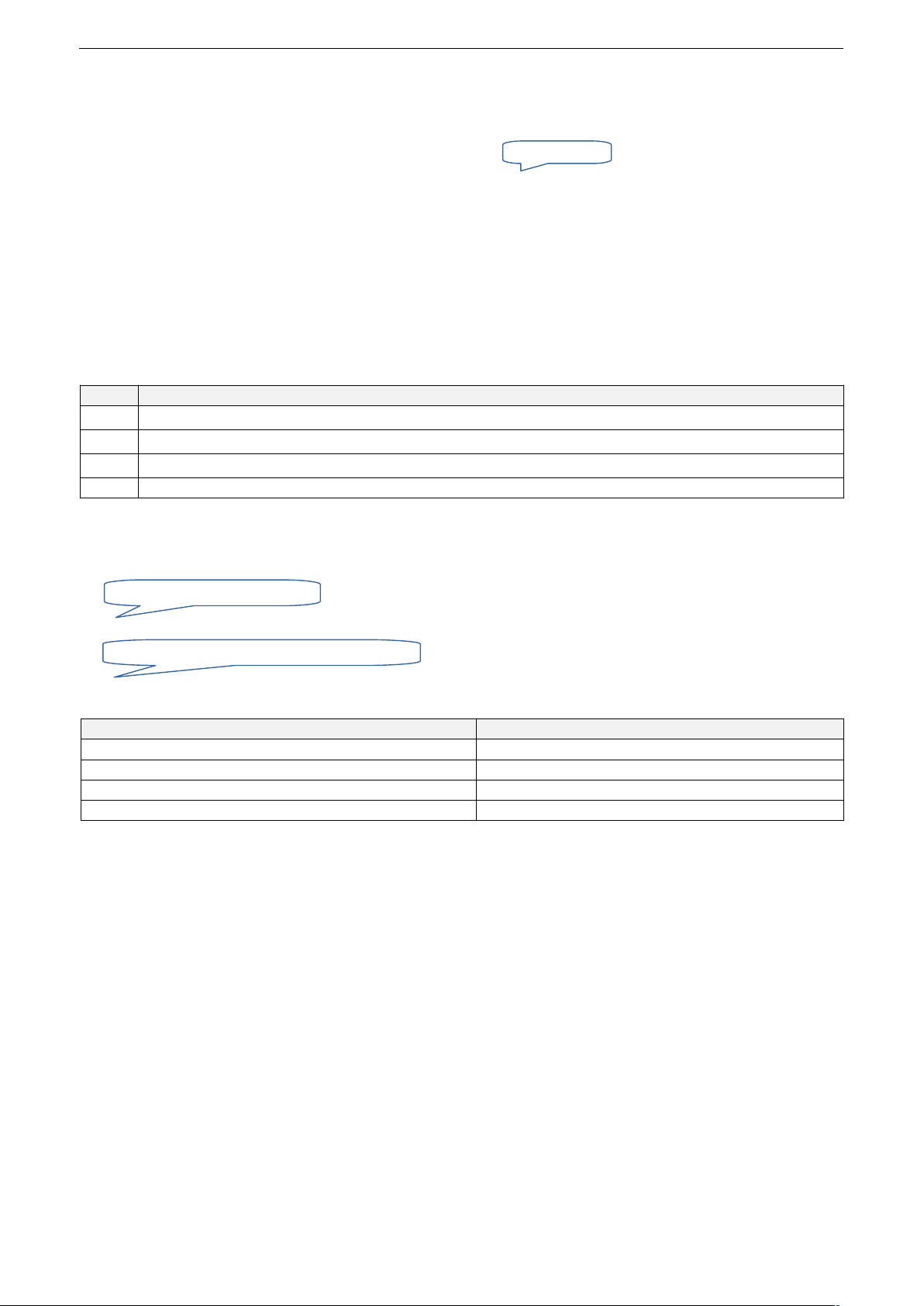
Key Response on key
5
Announcement of the monitoring functions and changes in the monitoring mode
7
Bypass waiting period and change to inactive monitoring mode
9
Bypass waiting period and change to active monitoring mode
others Initiate a test-call to desired calling number
6.4 Supervision mode
6.4.1 Announcement in supervision mode
The supervision function depending on the position of the selection switch will be announced as follows:
If the routine call is enabled:
6.4.2 Indication of the operating status on EasyAlarm®
LED status Operation mode
Green Waiting period 6.3
Green flashing every 4 seconds Supervision mode (activated) 6.4
Green is on and off for 4 seconds alternatively Supervision mode (deactivated) 6.4
Orange Telephone connection 6.6
6.4.3 Display of the operating status at the substation
EN81-28:2018: If no acknowledgement (DTMF C) is received from the receiver during the routine call, this is signalled by
an alternating flashing of the two EN81-70 symbols since version 8.51
13
Supervision I/II/III (de)activated
Operation mode, supervision I/II/III (de)activated
beep,beep,beep
Page 16

6.5 Alarm functions
Supervision functions
active on
Call in..
I II III
Emergency call
..hands-free connection Emergency call activated…
Misuse protection
6 6
..will be cancelled The door is open,…
Sensor-1 (can be deactivated)
6 6
..service connection Alarm due to Sensor-1
Sensor-3
..service connection Alarm due to Sensor-3
Power failure (can be deactivated)
..service connection Alarm due to power failure
Routine call
..service connection Periodical test call
6.5.1 Emergency call
The emergency call is triggered when the button is pressed during a specific time. EasyAlarm® starts to dial calling
number(s) according to the calling number sequence in hands-free connection.
Notes:
Factory delay time: 1 second. 9.12.3.
EN81-70: Yellow lamp on the sub-communication unit is activated.
Alarm forwarding to the building control system 9.14.2.
6.5.1.1 Misuse protection
If selection switch is on position III an alarm is only triggered, if the door contact does not change within a pre-programmed
period (it is recommended to program this time according to the longest possible travel of cabin, factory set to 30 seconds.
During this pre-alarm period following information is provided:
If the door state changes you will hear:
If the door contact does not change within this period, EasyAlarm® starts to dial calling number(s) according to the calling
number sequence in hands-free connection.
Notes:
Factory misuse protection time-out (=maximum travel time.): 30 seconds 9.11.2.
In case of emergency operation (supply loss and low battery) there will be no misuse protection.
6.5.2 Alarm due to Sensor-1 (Alarm contact)
If selection switch is on position II an alarm will be triggered in active supervision mode as soon as the Sensor-1 contact is
activated. EasyAlarm® starts to dial calling number(s) according to the calling number sequence in service mode.
6.5.3 Alarm due to Sensor-3 (Alarm contact)
On all position of the selection switch an alarm will be triggered as soon as the Sensor-3-contact is activated. EasyAlarm®
starts to dial calling number(s) according to the calling number sequence in service mode.
6.5.4 Alarm due to power failure
If the supply voltage fails for a defined period, EasyAlarm® calls routine number 9 in service mode.
Notes:
After power up EasyAlarm® mains power will be tested. If there is no mains power you will hear .
Once the power supply is detected, EasyAlarm® automatically activates power failure monitoring.
Factory network downtime: 120 Min. 9.5.1.
Alarm power failure to calling number sequence 9.5.2 (Factory setting to routine number 9) .
6.5.5 Routine call
When routine call is activated EasyAlarm® calls routine number 9 in the selected interval 9.4. To enable routine call,
make a remote access dial 6.9, enter touch-tone **#1 or a similar command 6.6.4.
EN81-28:2018: If no acknowledgement (DTMF C) is received from the receiver during the routine call, this is signalled by
an alternating flashing of the two EN81-70 symbols since version 8.51
14
Emergency call activated. You are about to be connected
Cause of alarm
The door is open. Emergency call deactivated. Alarm acknowledged
Emergency call activated
Alarm due to Sensor 3
Alarm due to power failure
Periodical test call
Emergency call activated. You are about to be connected
Power failure
Alarm due to Sensor 1
Page 17
6.6 Telephone connection
The colour of the indicator LED changes to orange during telephone connection.
6.6.1 Dial up time-out
EasyAlarm® tries to get in contact with called party for one minute (Profile P00) or two minutes (Profile P02/03/04). During
this time-out the Individual message will be announced periodically (P00) until the called party accepts call by sending 1
or just once if dial tone is present (P02/P03/P04) green lamp “speak”on sub-communication unit is activated.
Note:
Adjust dial-up time-out 9.7.1.
6.6.2 User announcement
User announcement is made up of
Notes:
Adjust user announcement 9.6.
At the beginning of any phone connection battery state and main voltage are checked. In case of a problem an
appropriated message will be announced.
6.6.3 Connection time-out
If the call is accepted or extended by sending 1 or 3 the connection time-out will be 4 minutes.
10 seconds before time-out there will be a warning .
Connection time-out can be renewed by sending touch-tone 1 or 3 for another 4 minutes.
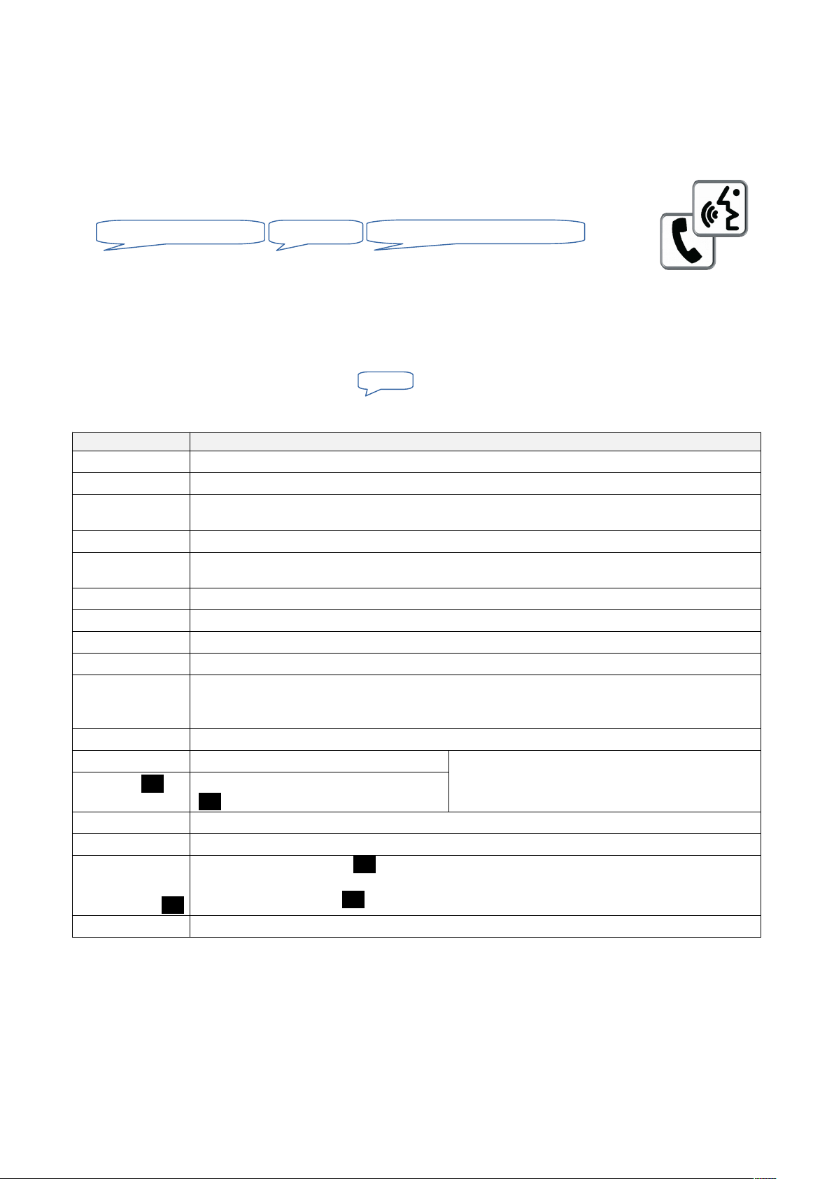
6.6.4 Touch-tone commands during telephone connection
Touch-tone DTMF Every valid command will be signalled
#
Announcement of PIN-Code (i.e. to identify elevator location)
0
Terminate telephone connection and acknowledge alarm
1
Switching to hands-free mode and restart connection time-out (4 minutes) and activate green lamp
EN81-70 on the sub-communication unit
2
Repeat announcements (Individual message / Cause of alarm)
3
Uphold telephone connection (4 minutes) and activate green lamp EN81-70 on the subcommunication unit
4
Deactivate output (i.e. "Help is coming" 9.14.2)
5
Announcement of current supervision mode as well as condition of the output
6
Activated output LMK-OUT (i.e. "Help is coming" 9.14.2)
7
DISARM: Deactivate power-failure- and Sensor-1-monitoring temporarily.
8
During alarm connection: Terminate telephone connection and pass on alarm to next party in
calling number sequence
If no alarm is active: Start test call towards calling number 8 6.8.2.1
9
ARM: Re-activate power-failure and Sensor-1-monitoring
**0
Announcement of calling number sequence After the announcement you are able to re-program
the calling number 5.3
** <n>
Announcement of calling number <n>
(<n> =1 to 9)
**##
Record individual message 5.4.1
**#0
Deactivate routine call
**#1
or
**#1 <h>
Activate routine. If left blank <h>, first routine call start after the programmed time-out 9.4
Start first routine call after <h>-hours. Follow-up calls in the time interval 9.4
**#2
Start routine call once without any delay
6.6.5 Service connection
In service mode the microphone and the loudspeaker remains inactive. This connection mode is used for technical alarms
(Sensor-1, Sensor-3, power failure, routine call and test call). By sending touch-tone 1 you may switch to hands-free
connection. If you change to hands-free connection three rings will alert a person inside the cabin for coming situation.
15
„Individual announcement”
to stop press 0, to speak press 1
Cause of alarm
Abort
Page 18

6.6.6 Hands-free connection
In hands-free microphone connection as well as loudspeaker are activated. Hands-free connection will be established
automatically in case of an emergency call and during test call.
6.6.6.1 Adjust hands-free volume
During hands-free connection you can increase volume by pressing local key #or decrease by pressing *. Level can be
adjusted in twelve steps (1 dB each) and remains stored. If hands-free volume or quality is poor please check assembly
instructions 3.2.
6.6.6.2 Adjust hands-free volume on sub-communication unit EA-LMK70C
Volume can be adjusted using the potentiometer volume (VOL).
Notes:
The additional amplifier is only active if supply voltage VIN is present.
If the volume is too high this can lead to an unwanted feedback 8.3.
6.6.6.3 Adjust volume of audio-outputs on sub-communication unit EA-LMK70T
Level of hearing-aid-loop or exciter can be adjusted using potentiometer volume (VOL).
Note:
This audio output is available only when the power VIN is applied, but not in emergency mode.
6.6.7 Acknowledge alarm / Terminate connection
A called party can either acknowledge and end call by sending touch-tone 0 or passing alarm to next calling number by
sending 8.
Notes:
You can stop call by pressing key 0 of the alarm unit.
If the alarm is programmed to a pager, the called person can confirm alarm during remote access after dialling-in.
6.7 Alarm repetition
If an alarm has not been acknowledged after passing all calling numbers within the calling number sequence you may add
some alarm repetitions 9.3. Factory setting: No alarm repetition.
6.8 Test call
6.8.1 Start with local key pad
When switched on, a test call can be started on the selected calling number 1-9.
If this calling number is not programmed there will a announcement , and calling number 1 will be dialled
instead.
Wait for connection and talk.
End connection: Press key 0 or switch to OFF.
Notes:
During test call ONLY the selected calling number will be dialled, i.e. the calling numbers sequence will be IGNORED!
5.2.
After four minutes telephone connection will automatically terminate if called party does not send any touch-tone
command (i.e. called subscriber can disconnect sending 0 or restart connection time-out using 3).
During inactive waiting period after power up key 9 and 7 activate or deactivate the supervision of Sensor-1 and
power-failure monitoring. Key 5 starts the announcement of the actual supervision mode.
The volume of the hands-free connection can be adjusted 6.6.6.
6.8.2 Start test call from remote during the telephone connection
6.8.2.1 Test call to calling number 8 in hands-free connection
If no unacknowledged alarms are present, touch-tone 8 activates a test call to calling number 8.
EasyAlarm® disconnects and start dialling calling number 8 after 15seconds. If calling number 8 is not programmed, calling
number 1 will dialled instead.
6.8.2.2 Test call to routine number 9
Touch-tone sequence **#2 activates routine call.
EasyAlarm® disconnects and start dialling calling number 9 within two minutes. If calling number 9 is not programmed, no
other number will be dialled instead.EN81-28:2018: If no acknowledgement (DTMF C) is received from the receiver during
the routine call, this is signalled by an alternating flashing of the two EN81-70 symbols since version 8.51
16
Calling number 1-9
Error
Alarm to calling number 8 activated
Routine call activated
Page 19

6.9 Remote access by dialling-in
If the alarm unit is switched to ON you can dial in from distance as following:
6.9.1 Direct dialling-in (Profile P00,01,03,04)
1. Dial phone number where EasyAlarm® is connected.
6.9.2 Two-step dialling-in (Profile P02)
1. Dial phone number where EasyAlarm® is connected.
2. Let it ring two times and hang-up.
3. Re-dial after 20 seconds.
After the programmed ringing cycles 9.8.1 EasyAlarm® answers call and asks for PIN-Code to access.
After entering correct PIN-Code EasyAlarm® establishes service connection (speaker and microphone remain inactive to
maintain the privacy of the person in the cabin).
By sending touch-tone 1 you may switch to hands-free connection. Doing so the green lamp on the sub-communication
unit will be activated (EN81-70) and three rings will inform a person inside the cabin.
If no touch-tone command is entered the connection will be terminated after connection time-out of 2 minutes.
Notes:
If there are any unacknowledged alarms, their number will be announced and the cause of alarm of the last call. By
sending touch-tone 0 you can acknowledge these alarms and terminate connection.
The number of ringing-cycles can be adjusted 9.8.1.
If touch-tone # is send instead of the PIN-Code, the number of ringing cycles for next access will be increased by 5
i.e. to access a modem connected in parallel.
Adjust dialling-in sequence 9.8.2.
If access should be in hands-free connection and/or without PIN-Code 9.8.3.
If the PIN-Code is incorrect or not entered within 15 seconds, EasyAlarm® disconnects after
=> try again and enter correct PIN.
PIN-Code is factory set to 0000. For safety reasons we recommend changing PIN-Code and program your individual
code according to the manual 5.5.
During inactive waiting period (indicated by a permanently activated green LED you can dial-in directly.
17
to stop press 0, to speak press 1
PIN-error, abort
Page 20
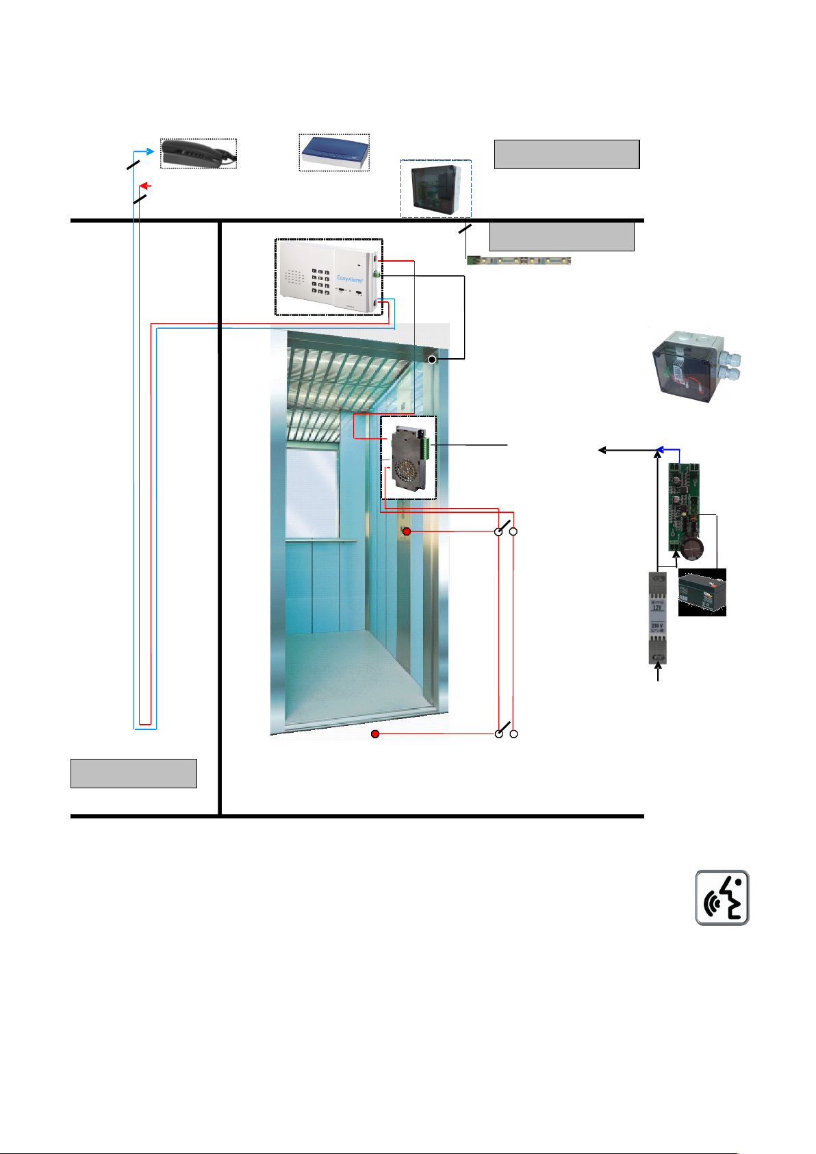
6.10 Machine room communication (EA-8-DPXM / EA-8-DPXFM)
With a standard telephone you are able to communicate with the cabin using EasyAlarm® EA-8-DPXM.
6.10.1 Wiring
Connect PIN3/4 of the machine room telephone (or modem) with PIN2/5 of -LINE.
6.10.2 Functional description
If the telephone/modem will be set off-hook, the hands free communication to the cabin will be activated
automatically. The green lamp on the sub-communication unit in the cabin will be activated.
The telephone/modem can dial-out to the PSTN by sending touch-tone 0. Doing so EasyAlarm® gives
access to the PSTN and the telephone/modem can dial out to any external number.
If you want to dial out with a modem automatically you have to program the number as following: 0 , <calling
number>."," will enter a dialling delay of 2 seconds.
An external connection will be disconnected automatically if EasyAlarm® has to dial out in case of an alarm.
In case of a dial-in a call will be signalled on the telephone/modem as ringing. If it answers the call before EasyAlarm®
the telephone/modem is connected to the external party => the dialling access of EasyAlarm® can be adapted
9.8.2.
Notes:
The functionality above is only available with applied supply (not in battery mode).
In case of a power loss the telephone/modem is connected to the PSTN in parallel to theEasyAlarm®.
18
Machine room
Cabin
2 2
Pit
MRphone
Modem
Incoming line (PSTN) or GSM interface
Emergency LED-light on cabin top or
inside panel frame
Supply:
UPS
8 - 35 V DC
EA-NSG
Emergency button
DIN-adapter
EA-ACDC-USV 12V
battery
230VAC
Emergency button
2
Misuse protection
Gateway
Page 21
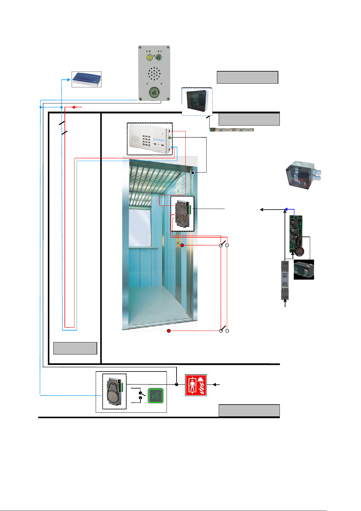
6.11 Fire brigade communication EN81-72
The fire service communication is based on the machine-room communication with alarm unit EA-8 DPXM in the cabin
6.10. Instead of the machine room telephone there will be a 118.0202E at the fire-brigade entry (Hands-free) and a
118.0204E in the machine room (Push-to-talk). Component Overview 10.8.
6.11.1 Wiring
6.11.2 Functional description
Activate fire brigade mode using key on the fire-brigade panel.
Handsfree between fire brigade entry 118.0202E and cabin (EasyAlarm from version V52) Symbols yellow / green
Push-to-talk in the engine room with 118.0204E:
o Talk button active: microphone active green symbol.
o Talk button inactive: microphone deactivated Symbol yellow.
6.12 Multi floor intercom
Component Overview 10.8.
19
Cabin
Machine room
Fire brigade
2
Pit
2
Modem
Fire brigade Mode:
Supply: 8 - 35 V DC
2
2
Emergency LED-light on cabin top
or inside panel frame
Supply:
UPS
8 - 35 V DC
EA-NSG
Emergency button
DIN-adapter
EA-ACDC-USV 12V
battery
230VAC
Emergency button
2
Incoming line (PSTN) or GSM interface
Misuse protection
Gateway
Page 22

7. USEFUL NOTES
7.1 Touch-tone commands
A called party can remote control EasyAlarm® to its full potential using touch-tone commands. Nowadays most of the
telephones in use are working on tone-dialling, also called DTMF or in-band signalling. Older telephones are using pulse
dialling. In case there is no tone-dialling telephone available, the features shown in section 6.6.4 cannot be used.
7.2 Announcement
Message / Cause
Individual announcement First announcement in case of an alarm => identification of the location
„Abort“ Connection terminated or programming aborted
„Alarm acknowledged Alarm stopped
„Alarm due to Sensor-1/3“ Alarm due to Sensor-1 or Sensor-3 contact / signal
„Alarm to calling number 8
activated“
Test call to routine number 8 activated by sending touch-tone 8 6.8.2.1
„Battery error” Battery is low 7.4
„Calling number sequence“ Calling number sequence 5.2
„Calling number“ Calling number 5.1
„Check phone line” No dial tone when switched on 8.2
„Emergency call activated” Emergency call activated by emergency button
„Emergency call deactivated,
alarm acknowledged”
Call has been acknowledged or stopped by a change of the door signal
„Error” Mistake while programming. The old value retain active
„Operation mode, supervision
(de)activated”
Announcement of the supervision mode 6.4
if announcement „operation“ = routine call activated
„Output activated” LMK-OUT output is activated (i.e. "Help is coming")
„Periodical test call“ Routine call active 6.5.5
„PIN“ Request to enter the PIN
„Power failure” External supply missing
„Programming acknowledged” Remote programming successful
„Programming deactivate: PIN“ Request to enter the PIN code to unlock programming
„Programming, Abort Incorrect remote programming
„To modify press star, to stop
press hash”
User guidance during programming
„<Operation> supervision I/II/III
(de)activated“
Announcement of the supervision mode 6.4
if announcement „operation“ = routine call activated
„Unacknowledged alarms: n“ Number of unacknowledged alarms
20
Announcement
Page 23
7.3 Functional tests
7.3.1 Test call
We advise to start test-call to check functionality of EasyAlarm® before starting operation 6.8.
7.3.2 Test alarms
Although the alarm unit with the exception of the battery is maintenance free, you should check at regular intervals all alarm
functions 8.5, in particular:
Emergency button
Door contact (misuse)
Sensor-1/3 contacts
7.3.3 Routinecall
EN81-28:2018: If no successful routine call has taken place (communication with routine call receiver, DTMF C), this is
signalled by an alternating flashing of the two EN81-70 symbols from version 8.51 on.
The routine call is performed
manually by pressing key 9 6.8.2.2
automatically when routine call is activated (announcement when switching on: Operation mode, supervision) 6.4
From version 8.51 always two hours after switching on, for older versions only after the set time span 9.4, and if the
routine call was activated with **#1 6.6.4
7.4 Battery check / replacement
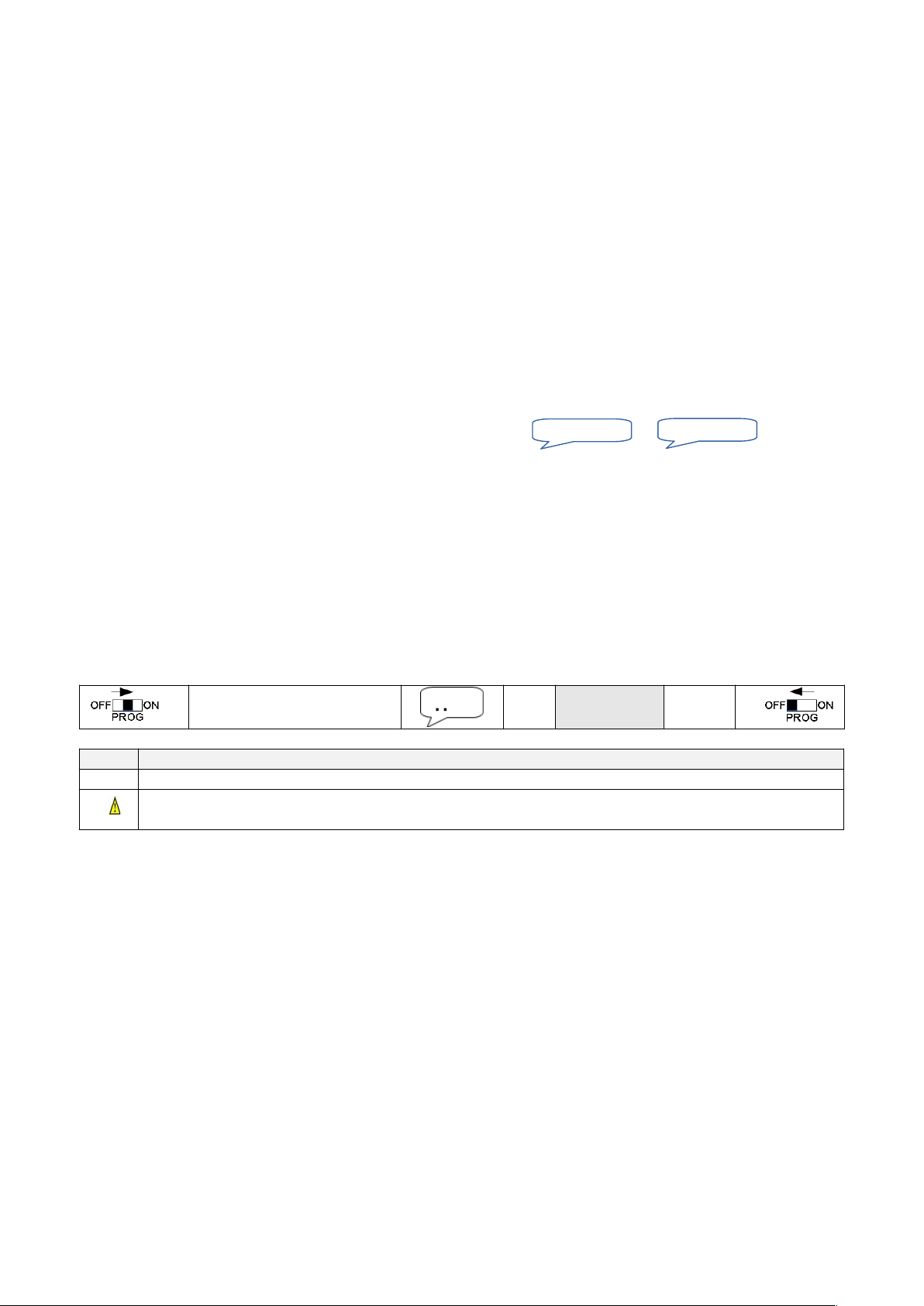
Change battery if you hear the following announcement after power-up: or
1. Set Function switch to OFF.
2. Disconnect EasyAlarm® from telephone network, by removing the telephone cord.
3. Open battery cover and remove battery.
4. Insert new battery and close battery compartment.
5. Reconnect EasyAlarm® to the telephone network.
Notes:
Always use fresh 9V-batteries.
Dispose the old battery properly.
Before opening battery compartment you have to disconnect the telephone-line. Otherwise you can get in contact with
telephone network voltage.
If you use backup supply voltage VIN you do not need 9V-battery. Doing so you can deactivate battery test:
*971327## *
Value
#
Value Info
0 Battery test activated (Factory setting)
4
Battery test deactivated
Warning: In case of a supply power down, only calling number 1 can be dialled (emergency operation)
7.5 Maintenance
Shift function switch to OFF and remove telephone cord. Clean EasyAlarm® if necessary using a moistened cloth and dry it
afterwards.
Note:
Do not use cleaning agents or solvent.
21
Piep,piep,piep
Battery error
Page 24
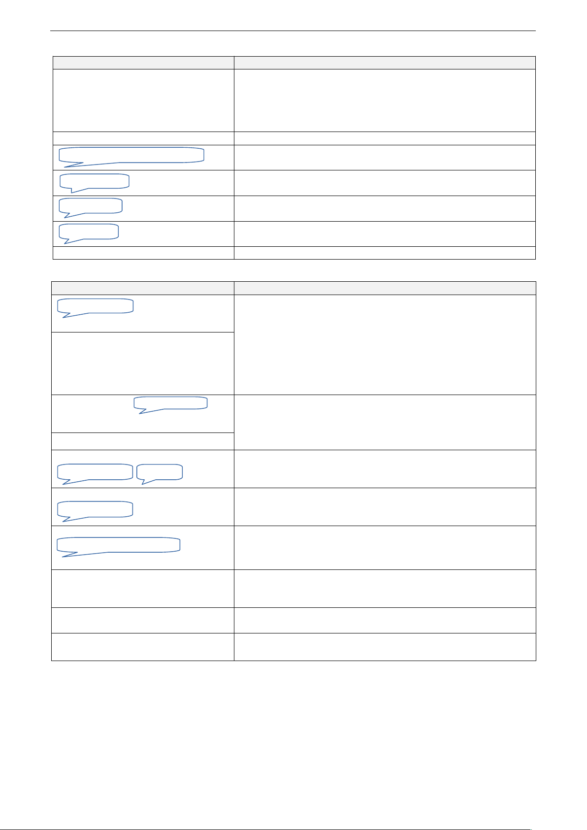
8. TROUBLE SHOOTING / ERROR HANDLING
8.1 General
Symptom Cause and /or remedy
Alternate flashing of the EN81-70 symbols No successful routine call in the last time interval 7.3.3
No or incorrect routine number 9 programmed
Routine call receiver does not send DTMF-C as acknowledgement
DTMF transmission faulty, i.e. DTMF-C does not arrive at the dialler
(IP telephony incorrectly set or similar 1.1)rt was set 6.6.4
LED indicator is inactive when switched on Supply voltage and battery missing
Programming mode is looked. Unlock 5.5.2
Supply voltage missing and low battery
Battery low. Replace immediately 7.4
Supply voltage missing / power adapter not plugged
Announcements do not make sense Voice chip inside alarm unit faulty (wrong text order)
8.2 Telephone line / Connection
Symptom Cause and /or remedy
No dial tone present during telephone line test:
Incorrect contact type 9.12 (Serial-No. < 90'000)
Alarm unit is not connected with PSTN
Insufficient insulation: Telephone and control connected / telephone
line grounded
Another telephone in parallel is already off-hook
Plug in cable, check cable
Use another telephone to verify telephone-line
No dial tones are audible during a test call
=> no tones are audible during the dialling
procedure
After connecting no
audible.
Alarm point only hears some touch-tones
* is an unwanted part of the calling number
* initiate a Point-ID-protocol alarm 5.1.1
Check calling number 5.1
Disconnection after approx., 30 seconds
No connection during test call:
Calling number (n=1 to 9) is not programmed
No connection during test call
and dial-tone audible
Calling number faulty
Called party does not answer call
Emergency-button works incorrect.
after power
up even if button is inactive
Incorrect contact type 9.12
Incorrect dial-up. During local programming
dial-tone are audible in the background
Incorrect contact type 9.12
Insufficient insulation: Telephone and control connected / telephone
line grounded
No outgoing call possible
Dialling-in access works fine
Subscriber did not pay bill
Outgoing calls not allowed
Announcements in communication seems to
be at the wrong time (too early, too late)
Adjust user announcement 9.6
Alarm point may replay announcement sending touch-tone 2
22
Programming deactivated: PIN
Battery error
Power failure
Check phone line
Announcements
Error
Calling number n
Emergency call activated
Calling number n
beep,beep,beep
Page 25

8.3 Quality of the hands-free communication / Touch-tone during connection
Symptom Cause and /or remedy
Speaker and microphone of subcommunication unit inactive
EXT-cable (RJ45) is only 6-wire instead of 8-wire
Alarm point is dominant during hands-free
connection (cabin can't be heard properly)
Disturbance or ripple on the phone line (hanging cable)
Telephone wires a/b are not separately laid (crosstalk of
neighbouring wires)
ADSL-interference: add ADSL Filter before EasyAlarm®
Incorrect assembly of sub-communication unit 3.2
Adjust hands-free volume 6.6.6
Strong background noise from the alarm point: fans, printer, lawn
mowers
Check by muting microphone of the telephone in the alarm point
Cabin is dominant during hands-free
connection (alarm point can't be heard)
Disturbance or ripple on the EXT-cable (RJ45) to sub-communication
unit
to verify: disconnect EXT-cable
Turn off power to the cabin and perform test call. If hands-free is fine
check the following points:
cable cut if possible as long as necessary!
Otherwise do not wind up excessive lengths up together with
other cables
Isolate cable as far as possible from "disturbing" cables in parallel
Problem due to excessive feedback,
Adjust hands-free volume 6.6.6
Check assembly of sub-communication unit 3.2
EasyAlarm® in protective housing => disable internal micro 3.1
Microphone on sub-communication unit or EasyAlarm® sealed
Strong background noise in the cabin: Vents
Activate BackGroundNoise-Filter (BGN) 9.15
Touch-tone commands during telephone
connection do not show any reaction:
i.e. alarm will not be acknowledged by 0
Used telephone does not support touch-tone or has not been
configured to it => for example pulse dialling
Used telephone is a system telephone
Activate touch-tone transparent mode
During internal calls with DECT, sometimes touch-tones are not
transmitted
8.4 Dialling-in
Symptom Cause and /or remedy
No access: EasyAlarm® always busy Incorrect contact type 9.12 (Serial-No. < 90'000)
Insufficient insulation: Telephone and control connected / telephone
line grounded
Telephone line circuit faulty i.e. lightning
No access: EasyAlarm® does not answer
call
Number of ringing-cycles is set to 0 9.8.1
Dialling-in sequence is set to two-step dial-in 9.8.2
Wrong dialling-in telephone number
Too many devices on the same phone line
No access: EasyAlarm® disconnects playing PIN-Code entered incorrect. Dial-in again and retry
PIN-Code not entered within 15 seconds
Message coming from an EasyAlarm® in parallel 9.8.3
No touch-tones received
Access without PIN-Code 9.8.3
Too many devices on the same phone line, the desired EasyAlarm®
has not taken the call
23
PIN-error,abort
Page 26
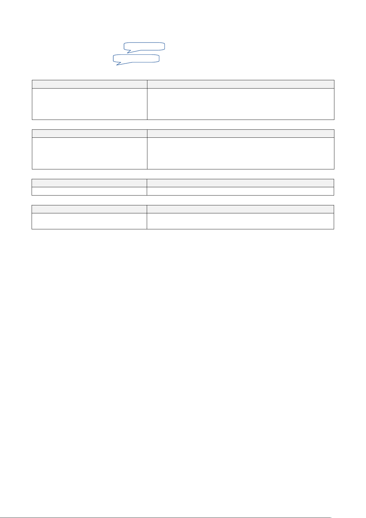
8.5 Wiring test
Sensor wiring (Sensor <n> =1,2,3) can be checked as following:
1. Set function switch to PROG.
2. Enter sequence ****.
Sensor contact in alarm position
Sensor contact back to idle
3. Set function switch to OFF.
8.5.1 Sensor-1: Alarm
Symptom Cause and /or remedy
Sensor contact has been initiated, but alarm
has not been passed on
Sensor-1 alarm only enabled on selection switch position II
Sensor-1 alarm inactive during waiting period (LED indicator is green
permanently)
Sensor-1 monitoring temporarily deactivated
8.5.2 Sensor-1: Misuse-protection filter
Symptom Cause and /or remedy
Misuse-protection filter does not work
6.5.1.1
Misuse protection filtering is only enabled on selection switch position
III
Misuse signal was not detected, because signal change was to short
(plus < 5 seconds)
8.5.3 Sensor-2: Emergency-button
Symptom Cause and /or remedy
Inverse operation function Incorrect contact type 9.12
8.5.4 Sensor-3: Technical alarm
Symptom Cause and /or remedy
Sensor contact has been initiated, but alarm
has not been passed on
Sensor-3 alarm inactive during waiting period (LED indicator is green
permanently)
24
<n> activated
<n> deactivated
Page 27
9. SPECIAL PROGRAMMING
All parameters remain stored even if EasyAlarm® is switched off or battery has changed.
Programming mode can be locked to secure against unintended programming during operation 5.5.1.
In that case on position PROG you will hear
Changing these parameters below does influence the operating mode. Therefore only necessary parameters should be
changed. Please test behaviour before going into operation.
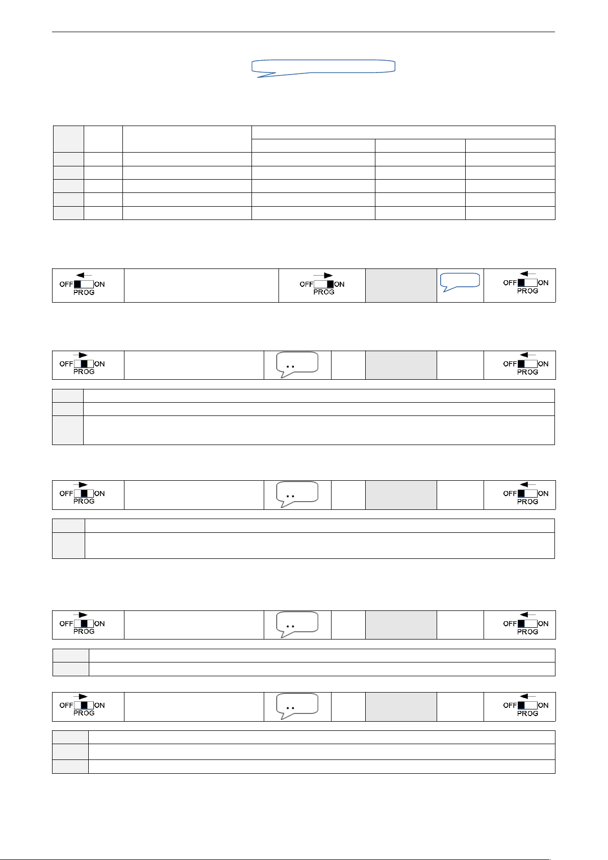
9.1 Ready/Modify profile
Value Profile Alarm units Profile-Overview
User announcement Connection time-out Dialling-in
7 00 EA-8-DPX/EA-8-DPXM Repeated every 5 second 1 minute Directly
8 01 EA-8-DPXF/EA-8-DPXFM single 2 minutes Directly
9 02 EA-8-DPXN (PLUS) single 2 minutes Two-step
10 03 EA-8-DPX/EA-8-DPXM single 2 minutes Directly
11 04 EA-8-DPX/EA-8-DPXM Repeated every 8 seconds 2 minutes Directly
Warning: After changing profile you have to activate factory settings as follows 9.2.
9.2 Factory settings (Default Value)
EasyAlarm® can be reset to default values:
Keep key 3 and #
pressed simultaneously
Release both
keys
9.3 Alarm repetitions
EasyAlarm® An alarm is triggered, as soon as the alarm criteria is fulfilled and the waiting period has expired. In some
cases it might be useful to repeat an alarm as long until an acknowledgement is received:
*971353## *
Value
#
Value Info
0 EasyAlarm® calls calling numbers within the calling number sequence just once (Factory setting)
1..9 EasyAlarm® starts calling the calling numbers within the calling number sequence until the alarm is confirmed by
sending 0 or until the programmed value n of alarm repetition is reached
9.4 Routine call intervall
The delay between two routine calls to calling number 9 (Control centre / WinMOS) can be read out or modified as follows:
*971328## *
Value
#
Value Info
1..254 EasyAlarm® dials calling number 9 every 1..254 * 20 minutes.
(Factory setting: 216 *20 min = 4320 min = 72 h = call every three days)
9.5 Power failure
9.5.1 Power failure time-out
The duration of power loss before the alarm unit starts a call can be read out or modified as follows:
*971363## *
Value
#
Value Info
1..255 Duration in steps of 10 minutes (Deviation -0/+10 min) (Factory setting: 12 *10 min = 120 min = 2 h.)
9.5.2 Calling number in case of power failure (new from version 8.45)
*971362## *
Value
#
Value Info
1
Alarm to standard calling-number sequence defined by **0 (Standard up to Version 8.44)
3 Alarm to calling number 9 (routine) (Factory setting from Version 8.45)
25
Programming deactivated: PIN
„Profile“
Page 28
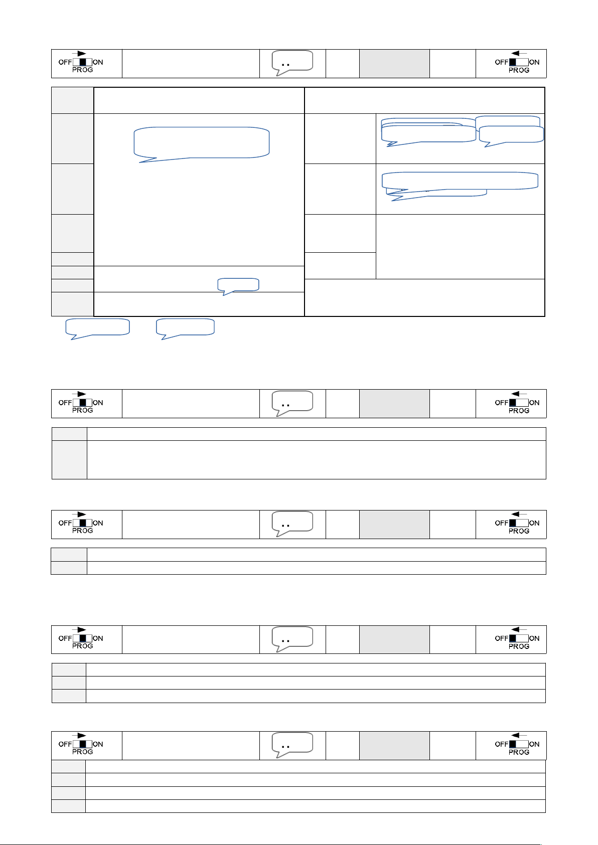
9.6 User announcement
The repetition time and type of announcements during the connection can be read or modified as follows:
*971320## *
Value
#
Value Announcement after triggering alarm an during
misuse protection delay
Announcement during telephone connection
0 Periodical announcement of the cause of alarm
(Factory setting: 0)
One time
1..200
Periodical
every
1..200 Sec.
201..250
Periodical
every
201..250 Sec.
252
One-time
253 Periodical announcement of the cause of alarm
In case of an emergency call
254
None *)
255 None *)
*) and will be announced without exception.
9.7 Connection time-outs
9.7.1 Dial-up
The Dial-up time-out can be read out or modified as follows:
*971350## *
Value
#
Value Info
1..255 Dial-up time-out in steps of 10 seconds
(Factory setting: 12 *10 s = 120 s = 2 minutes, Profile P02/P03/P04)
(Factory setting: 6 *10 s = 60 s = 1 minute, Profile P00)
9.7.2 Hands-free connection
Connection time-out after receiving touch-tone 1can be read out or modified as follows:
*971351## *
Value
#
Value Info
1..255 Time-out in steps of 10 seconds (Factory setting: 24 *10 s = 240 s = 4 minutes)
9.8 Dialling-in (remote access)
9.8.1 Number of ringing-cycles
The number of ringing cycles until EasyAlarm® answers the call can be read out or modified as follows:
*971347## *
Value
#
Value Info
0 EasyAlarm® does not answer any call
2..9 EasyAlarm® answers call after 2 to 9 ringing cycles (Factory setting: 2)
9.8.2 Dialling-in sequence
Behaviour on dialling-in can be read out or modified as follows:
*971370## *
Value
#
Value Info
0 Direct access 6.9.1 (Factory setting for Profile P00/01/03/04)
1 Access in two steps 6.9.2 (Factory setting for Profile P02)
10 Swiss speciality: “Connection hold time 2 minutes” in analogue PSTN. 9.10
26
activated
Emergency call activated,
you are about to be connected
„Individual message“
to stop press 0, to speak press 1
„Individual message“
Cause of alarm
to stop presst 0
Battery error Power failure
„Individual message“
Cause of alarm
Page 29
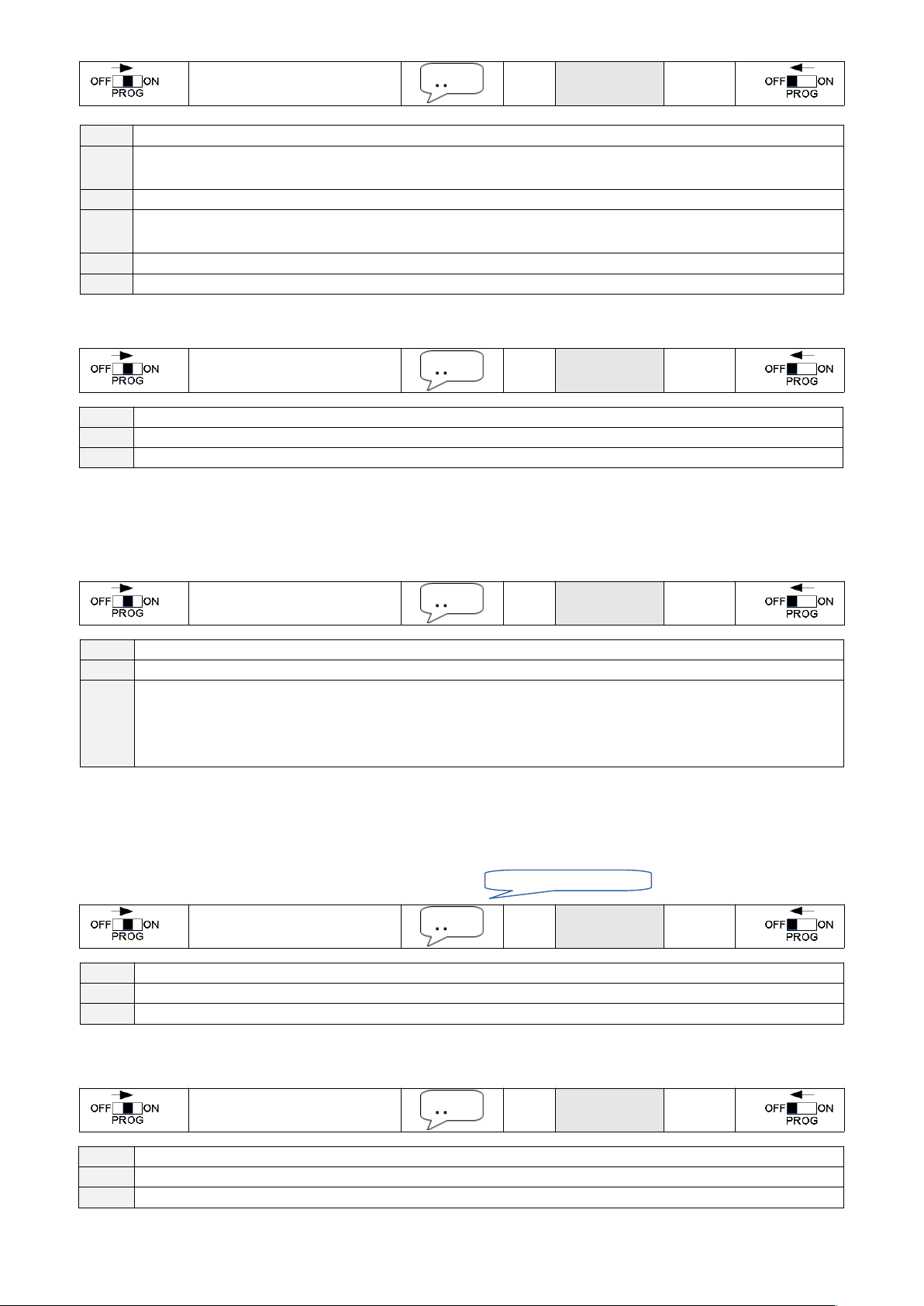
9.8.3 Connection mode after dialling-in
Connection mode after dialling-in can be read out or modified as follows:
*971371## *
Value
#
Value Info
0
After PIN-Code-entry Connection in service-mode Hands-free connection using DTMF 1
(Factory setting)
1 After PIN-Code-entry Connection directly in hands-free mode, indicated by three rings
2 After PIN-Code-entry or time-out 15s Connection in service-mode Hands-free connection using DTMF
1
3 After PIN-Code-entry or time-out 15s Connection directly in hands-free mode, indicated by three rings
5 Without PIN-Code-query Connection directly in hands-free mode, indicated by three rings
9.9 Remote programming
Remote programming of calling number/number sequence/individual message can be read out or modified as follows:
*971376## *
Value
#
Value Info
0 Remote programming disabled
1 Remote programming enabled (Factory setting)
9.10 Dialling delay for EA-8-DPXN
To ensure that EasyAlarm® can dial out, even if the line is already seized through a downstream telephone/modem, it
separates the line before dialling out.
Swiss speciality: “Connection hold time 2 minutes” in analogue PSTN => If an incoming call is answered the pre-alarm timeout is extended (up to 120s) to assure that an alarm can be triggered.
*971324## *
Value
#
Value Info
0 No delay (Factory setting for Profile P00, P01, P03, P04)
1 Dialling delay activated (Factory setting for Profile P02 / DPXN+).
In case of Swisscom-hold-up additional program registers
*971372## to *4#
*971370## to *10#
9.11 Sensor-1: Misuse-protection
Sensor 1 can be used two ways:
On selection switch position II it will be used as alarm sensor
On selection switch position III it is used to detect a change of door position (misuse protection)
9.11.1 Sensor-1 as alarm input
Sensor-1 activation results in a (selection switch on position II):
*971356## *
Value
#
Value Info
21 Alarm if contact closes or signal is applied (Factory setting)
23 Alarm if contact opens or signal cease to apply
9.11.2 Sensor-1 as misuse-protection time-out
If the door contact changes within this time-out (Selection switch position III) an emergency call will be aborted => misuse
protection. This time-out can be read out or modified as follows:
*971348## *
Value
#
Value Info
0 Misuse-protection inactive
1..255 Timer in steps of 1 second (Factory setting: 30) => Adjust to maximum time of cabin travel
27
Alarm due to Sensor-1
Page 30
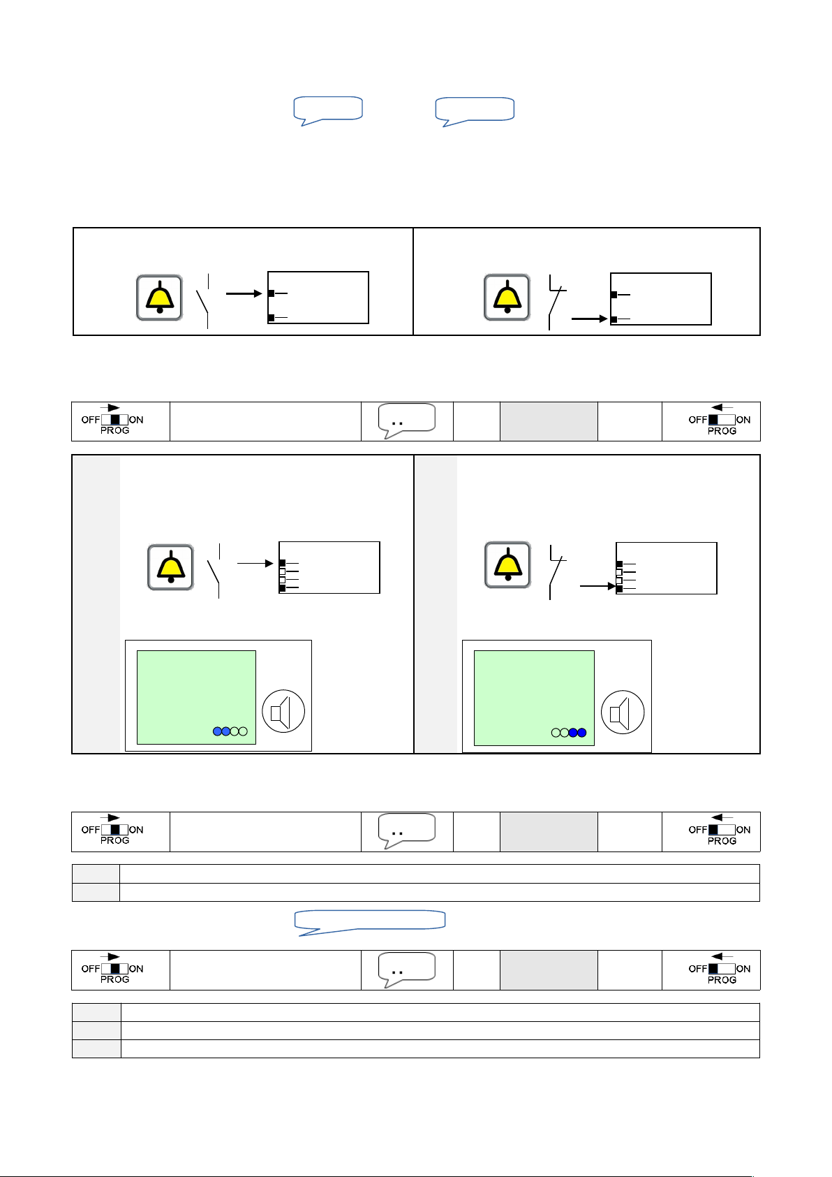
9.12 Sensor-2: Emergency-button
The button must be floating (potential free), i.e. separate from the alarm horn contact. When you use the unipolar button of
an existing installation use accessories EA-NT-IN 10.4.
To verify contact type set function switch to PROG and enter ****.
When pressing button, you should hear , back to idle . . Otherwise adjust contact type:
The setting of the jumper / switch is necessary for emergency operation powered from the telephone line, if battery and
supply should fail simultaneously. In this mode EasyAlarm® can only call the first phone number, without any
announcements. In case of wrong setting the permanently current may block the telephone line.
9.12.1 Contact type selection for new EasyAlarm® from Serial-number 90'000
For alarm units with serial-No. 90'000 ONLY the slide switch must be set Do NOT adjust software!
Normally open contact (Factory setting) Normally closed contact
Set slide switch inside battery compartment to NO Set slide switch inside battery compartment to NC
9.12.2 Software selection for EasyAlarm® up to Serial-number 89'999
For units up to serial-No. 89'999 you need to program appropriated value according table below and set slide switch slide/
jumper. The emergency-contact type can be read or modified as follows:
*971360## *
Value
#
Value Info (Factory setting) Value Info
33 Normally open contact
from Serial-No. 57'100 to 89'999:
Set slide switch inside battery compartment to NO
from Serial-No: 50'000 to 57'099:
Jumper on PCB away from speaker (left position)
Leiterplatte
PCB
NO
Jumper
35 Normally closed contact
from Serial-No. 57'100 to 89'999:
Set slide switch inside battery compartment to NC
from Serial-No: 50'000 to 57'099:
Jumper on PCB towards speaker (right position)
Leiterplatte
PCB
NC
Jumper
9.12.3 Activation time for emergency button
EasyAlarm® triggers an emergency call only if the button has been activated longer as certain time. This time can be read
out or modified as follows:
*971379## *
Value
#
Value Info
1..255 Contact time in steps of 20 ms. (Factory setting: 50 *20 ms = 1000 ms = 1 s)
9.13 Sensor-3: Technical alarm
Sensor-3 activation results in a
*971361## *
Value
#
Value Info
1 Alarm if contact closes or signal is applied (Factory setting)
3 Alarm if contact opens or signal cease to apply
28
Alarm due to Sensor-3
2 activated
NC
NC
2 deactivated
NO
NO
NO
OFF
OFF
NO
OFF
OFF
Page 31
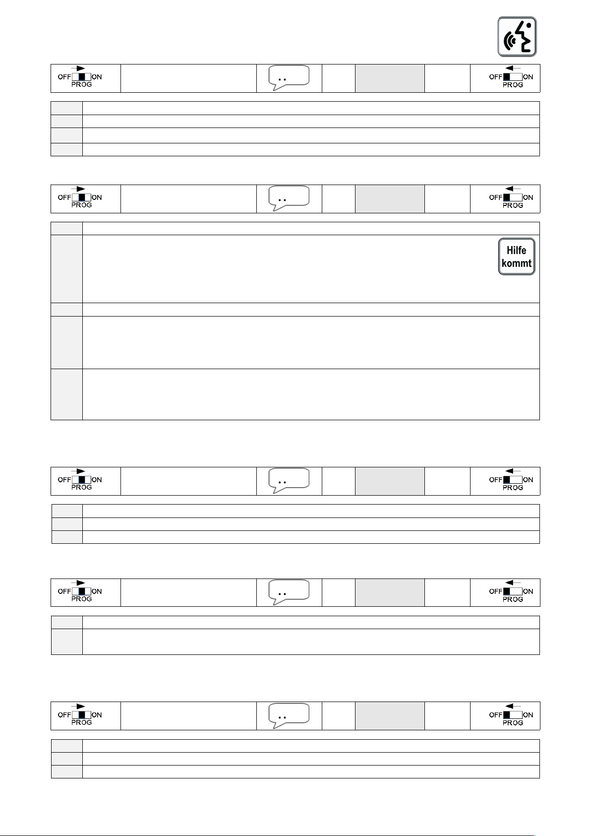
9.14 Control sub-communication unit
9.14.1 EN81-70 lamps
The type of activation of the symbols can be read out or modified:
*971369## *
Value
#
Value Info
0 Yellow and green lamp/LED disabled.
2
Green lamp/LED must be activated manually during connection using 1 (Factory setting).
4 Green lamp/LED will be activated automatically during connection
9.14.2 Output LMK-OUT(-)
Configuration can be read out or modified:
*971337## *
Value
#
Value Info
208 Mode "Help is coming" lamp
Activate "Help is coming" by sending 6 during connection.
"Help is coming" will be switched off, by sending 4 during connection /
when there is a change in door signal (S1) / if alarm remains unacknowledged / if there is a new alarm (i.e.
emergency button pressed again) / after a periodical test!
216 New from software 8.45: same as 208 + additional "Help is coming" set with every received touch-tone command
193 Mode „Emergency call active“ => Connection to external building control system (Factory setting)
The output „Emergency call active“ is switched on after misuse protection time-out.
It is switched off, when there is a change in door signal (S1) / there is a new alarm (i.e. emergency button
pressed again) / after a periodical test! / by sending 4 during connection
226 Mode „activated, if the alarm remains unacknowledged“ => e.g. DECT-Solution
The output is switched on, when an alarm remains unacknowledged.
The output switches off, when there are no more unacknowledged alarms / in case of a door status change
(Sensor-1) / in case of an new alarm / periodical test / in case of a machine room communication
9.15 Background-Noise filter
In case of a loud background noise in the cabin (i.e. ventilator, train station..) you may activate BGN-function to improve
hands-free communication:
*971335## *
Value
#
Value Info
0 BGN disabled (Factory setting)
103 BGN enabled (in case of intensive noise in the cabin)
9.16 Hands-free volume adjustment
The Hands-free volume of the alarm-unit can be read out or modified:
*971366## *
Value
#
Value Info
0..15 Attention! In case of hand-free communication problem try with low values at the beginning. With consideration to
raise the volume level is adequate (8 as maximum) (Factory setting: 8)
9.17 DTMF optimization for mobile connections
To increase the success rate of data transmission using DTMF tones (WinMOS or other Routine receiver), it is
recommended to adjust the tone duration as follows: Available from software version 8:39!
*971336## *
Value
#
Value Info (duration = (value-76) * 20msec)
80 Tone duration for land-line use 80msec (Version 8.39 up to 8.48) Factory setting)
84 Tone duration optimized for the mobile network to 160msec (Factory setting from 8.49)
29
Page 32
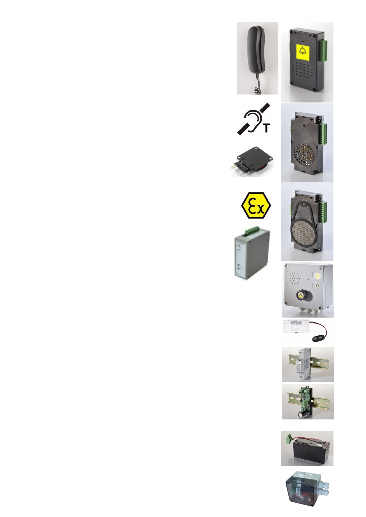
10. ACCESSORY
10.1 Machine room telephone(Art. No: 118.0120)
Cable: 3 m. Suitable for operation with EA-8-DPXM or EA-8-DPXFM 6.10
10.2 Sub-communication units
Housing material: ABS
10.2.1 EA.LMC-EC (Art. No: 118.0158)
Passive: Micro/Speaker and integrated EC-button (normally open)
Dimension: 114 x 58 x 21 mm (L x W x H), W incl. plug: 74 mm
10.2.2 EA-LMC70 (Art. No: 118.0155) / EA-LMC70-EC (Art. No: 118.0156)
Dimension: 114 x 58 x 21 mm (L x W x H), W incl. plug: 74 mm
EC: integrated EC-button (normally open)
10.2.3 EA-LMK70C (Art. No: 118.0160)
Dimension: 112 x 56 x 21 mm (L x W x H), W incl. plug: 74 mm
10.2.4 EA-LMK70C-WG (Art. No: 118.0161)
Same as 118.0160 but with IP54 protection using suitable drilling pattern
10.2.5 EA-LMK70T (Art. No: 118.016x)
Same as 118.0160 but including amplified audio-output for ..
Hearing-aid-loop (Set No: 118.0165)
Exciter (Set No: 118.0166)
10.2.6 LMK70-ATEX
10.2.6.1 ATEX-Barrier (Art. No: 121.0390)
Primary voltage: 8 to 35 V DC
Protection class: II (1) GD [Ex ia] IIC
[Ex ia] IIIC
45 x 118 x 138 mm (L x W x H)
10.2.6.2 Zone 0 (Art. No: 121.0370)
Protection class: Gas: II 1G Ex ia IIC T4 Ga
112 x 56 x 22 mm (L x W x H). W incl. plug 74mm
10.2.6.3 Zone 20 (Art. No: 121.0380)
Protection class: Dust: Housing incl. button + EN81-70 symbols
II 1 GD Ex ia IIC T4 Ga
Ex ia IIIC TXX °C Da IP64
160 x 160 x 91 mm (L x W x H)
or 188 x 160 x 109 mm (L x W x H) incl. PG11 and button
10.3 Power supplies
10.3.1 Voltage converter EA-DCDC (Art. No: 100.0290)
PCB mounted in the battery compartment with connector 8 to 35 V DC / isolation 3kV
including connection cable for emergency call button (article No: 118.0140)
10.3.2 DIN-adapter EA-ADC-USV (Art. No: 118.0117)
Primary voltage: 230 V +- 15% / 50 Hz
Secondary voltage: 14.3 V DC / 10 W
Dimension: 17.5 x 93 x 68.5 mm (L x W x H) / DIN-Rail 1 unit
10.3.3 DIN-adapter EA-DCDC-USV (Art. No: 118.0119)
Primary voltage: 9 to 35 V DC
Secondary voltage: 14.3 V DC / 10 W
Dimension: 17.5 x 93 x 68.5 mm (L x W x H) / DIN-Rail 1 unit
10.3.4 Uninterrupted power supply interface EA-NSG (Art. No: 100.0117)
In combination with DIN-adapter 118.0117 or 118.0119 and a 12V-battery you get an uninterrupted power supply (UPS)
Primary voltage: 14.3 V DC i.e. from Art. No: 118.0117
Secondary voltage: 12 V DC for emergency light (max. 200 mA)
12 V DC for alarm unit (max. 400 mA)
13.8 V DC Charging voltage for lead acid battery
Dimension: 35 x 90 x 32 mm (L x W x H) / DIN-Rail 2 units
10.3.5 Uninterrupted power supply USV-230VAC-12V-IP (Art. No: 121.0117)
Article-no: 100.0117+ 118.0117 + 100.0880 pre-mounted in IP65 housing
Dimension: 110 x 110 x 90 mm (L x W x H)
30
+
+
Page 33
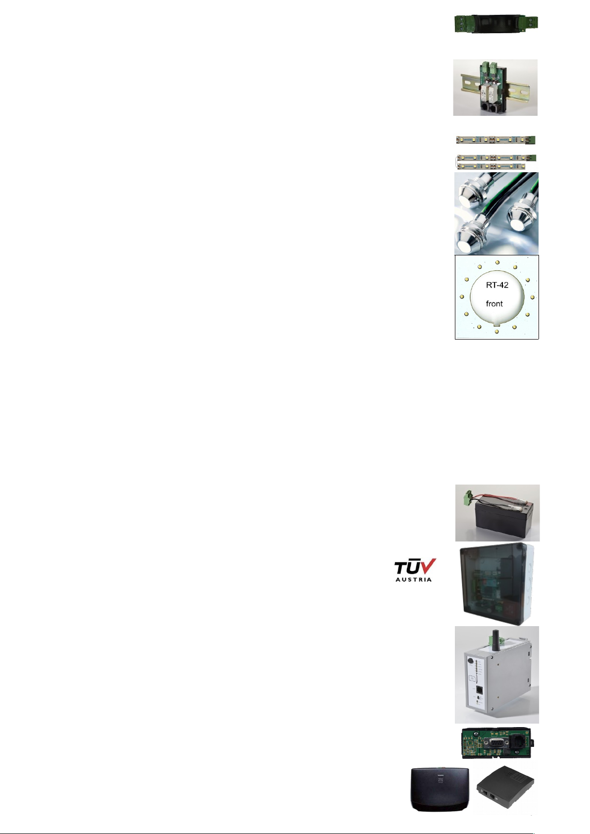
10.4 Emergency-button interface EA-NT-IN (Art. No: 100.0250A)
Alarm-input: 4.8 to 35 V DC / limited to 10 mA / Isolation: 1.5kV => (parallel to horn
Output-switch: Contact NC or NO: max. 350 V/0.12 A (30 Ohm) => to plug X2
10.5 Misuse-protection interface EA-2DOOR (Art. No: 100.0260A)
Door-state-signals (2x): active 10 to 35 V DC, status LED
Dimension: 35 x 90 x 30 mm (L x W x H) / DIN-Rail 2 units
10.6 Emergency lights (Art. No: 100.087x)
10.6.1 LED-strip 10 cm(Art. No: 100.0870) self-adhesive
Suitable to transparent frames (100.0231) 3.2.1.2
Specification: 12 V DC +/- 15% / 0.8 W / 52 lm (16 cd 120°)
Dimension: 117 x 9 x 9 mm (L x W x H)
10.6.2 LED-strips 2 x 10cm (Art. No: 100.0873) self-adhesive
Like 100.0870, but 2 stripes for light upwards and downwards
Specification: 12 V DC +/- 15% / 1.6 W / 104 lm (16 cd 120°)
Dimension: (100+117) x 9 x 9 mm (L x W x H)
10.6.3 LED-screw (Art. No: 100.0872) / IP67
Specification: 12 V DC +/- 15% / 0.2 W / 4 lm (44 cd 20°)
Mounting: Screw M8 Cable: 25 cm
10.6.4 LED-Ring (Art. No: 100.0879)
Specification: 4 to 15 V DC / 1 W
Dimension: 52 x 52 x 6 mm (L x W x H)
Suitable to polycarbonate front panels (Art. No: 100.0211 / 0212 / 0213) in Rx42-gap 3.2.1.1
10.7 Telephone line interfaces
10.7.1 Alarm forwarding over mobile network / Gateway
Simulates the analogue telephone line for EasyAlarm® and is compatible with the protocols WinMOS ® 300 and Point ID.
Notes:
The antenna should be mounted in a fixed location (e.g. in the engine room), to ensure a stable reception situation.
In the case of an retrofit (SNEL, ESBA), where no telephone wires in the hanging cables are available, the gateway
can be mounted on top of the cabin, if the reception is ensured throughout the entire travel the elevator.
If the coverage is inadequate or fails completely, the system must be placed out of service automatically, for example
with a command “move to ground floor” send to the elevator control. For this purpose, the gateway includes a potential
free relay contact (NO or NC).
Beware of prepaid SIM: Where appropriate in the case of alarm, no funds are available. A postpaid or a prepaid with
automatic reloading is preferable.
Connectors: 1 x Line (for i.e. alarm units EasyAlarm® / Exicall EN70 / MINI
1 x permanent 12V-output for alarm units and horn
1 x switched 12V-output for emergency light
1 x Relay-contact Operation monitoring “System ready“
1 x SMA-antenna jack (patch sticking antenna included)
Status: reception level with LED
Backup: 12 V battery (e.g. Art. No: 100.0880)
Approval: TÜV AUSTRIA, Report number: AT – 08 / 0028
10.7.1.1 EA-UMTS-IP (Art. No: 100.0802BU) / EA-UMTS-IP-LIGHT (Art. No: 100.0801BU)
Supply voltage: 230 V AC / 50 Hz
Dimension: 182 x 180 x 63 mm (L x W x H) / protective housing IP65
10.7.1.2 EA-UMTS-DIN (Art. No: 100.0812BU) / EA-UMTS-DIN-LIGHT (Art. No: 100.0811BU)
Supply voltage: Art. No: 1AC.0812B: 230 V AC / 50 Hz (incl. Art. No: 118.0117)
Art. No: 1DC.0812B: 9 – 35 V DC (incl. Art. No: 118.0119)
Dimension: 45 x 118 x 135 mm (L x W x H) / DIN-Rail
add 17.5 x 93 x 68.5 mm for DIN-adapter
10.7.1.3 RDT Remote-Data-Transmission modules for 100.802B or 100.0812B
Data-Module: Art. No: 100.0850: DB9 for compatible elevator controls
Art. No: 100.0851: Mini-USB for compatible elevator controls
Dimension: 35 x 90 x 30 mm (L x W x H) / DIN-Rail 2 units
10.7.2 DECT-Interface
DECT-Interface for wireless connection between cabin and machine room , when there is
no hanging cable available for telephone line.
31
Page 34
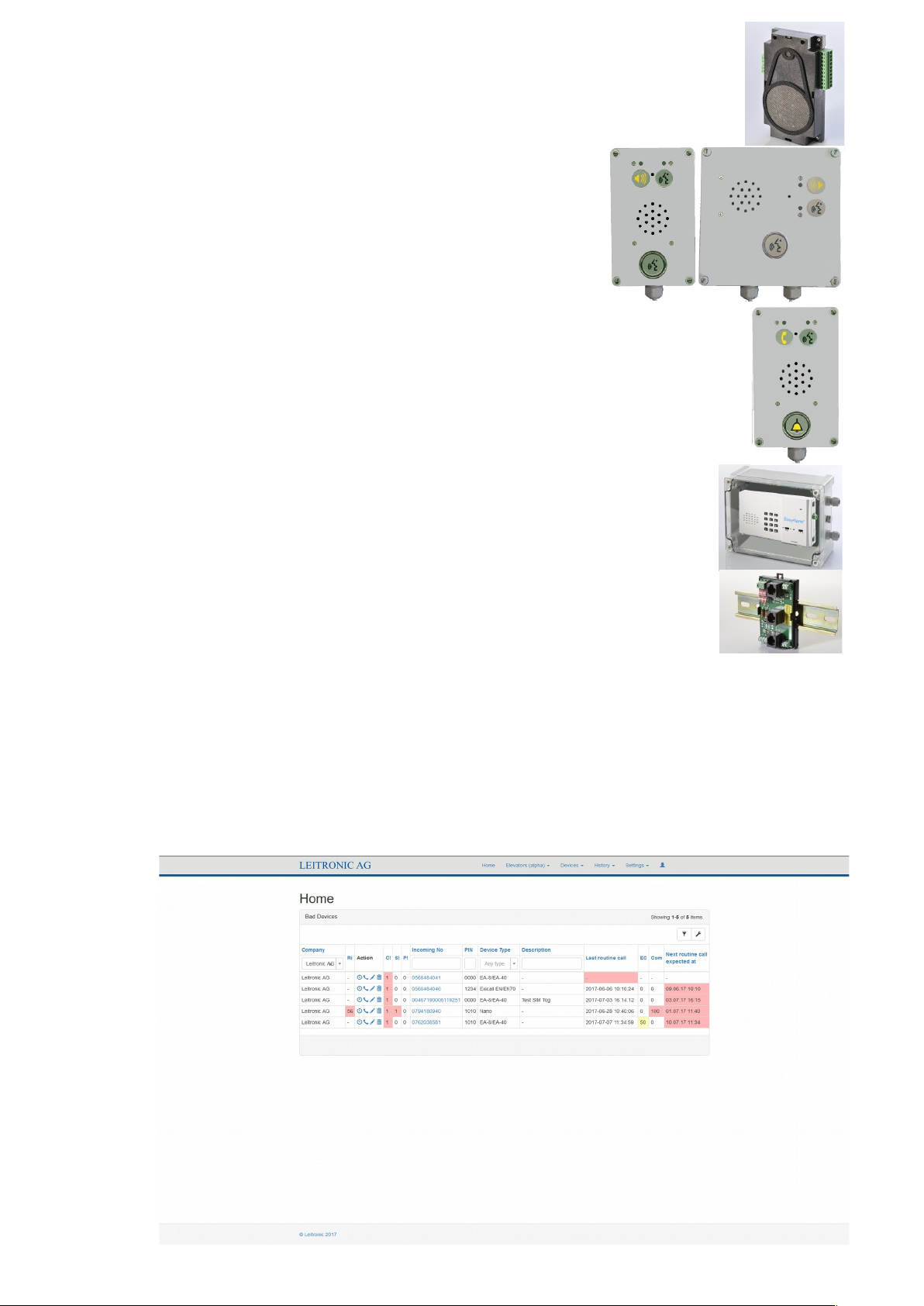
10.8 Fire-brigade communication EN81-72
Cabin 6.11: Art. No: EA8 DPXM LMK70C-WG
(Alarm unit EA-8-DPXM + sub-communication unit LMK70C-WG)
10.8.1 Remote-communication unit (Art. No: 118.0202E): Flash mount
Fre-brigade entry (hands-free) / Alternative design 10.8.3.
10.8.2 Multi floor communication unit (Art. No: 118.0204E): Flash mount
Machine room / additional floors (push-to-talk) / Alternative design 10.8.4.
10.8.3 Remote-communication unit (Art. No: 118.0212E): Surface mount
118.202E mounted in protective housing IP54 incl. Talk-button and symbols.
10.8.4 Multi floor communication unit (Art. No: 118.0214E):Surface mount
118.204E mounted in protective housing IP54 incl. Talk-button and symbols.
10.8.5 Multi floor communication unit/timer (Art. No: 118.0215E):Surface
mount
In the machine room like 118.0214E including adjustable timer module
10.9 Protective housing EA-IP-EN70-EC (Art. No:100.0730)
IP54-housing for sub communication units 10.2 incl. Emerg.-button.
10.10 Protective housing for EasyAlarm® EA-IP-BOX (Art. No: 100.0700)
EA-IP-BOX with transparent lid protects alarm unit up to IP65.
The internal EasyAlarm® microphone must be disabled to avoid feedback.
10.11 Lightning protection interface (Art. No: 100.0328)
Protects the telephone input of EasyAlarm® from voltages higher than 150 V and filters ADSL
signals. The interface is also a distributing adapter for connecting a machine-room telephone (MRphone) or the remote communication unit.
Dimension: 90 x 52 x 30 mm (L x W x H) / DIN-Rail 3 units
Connectors: RJ12 and screw terminals
10.12 Routine call management (portal.leitronic.ch)
Leitronic offers a web-based solution to monitor the devices according to EN81-28. With a login from Leitronic AG you will
be given the opportunity to:
1. manage routine call (every 72 h according to EN 81-28)
2. programming EasyAlarm® EXICALL & EN70 & Nano & Mini
Calling number
PIN-Code
Dialling-in / Remote access
Routine call interval
32
Page 35
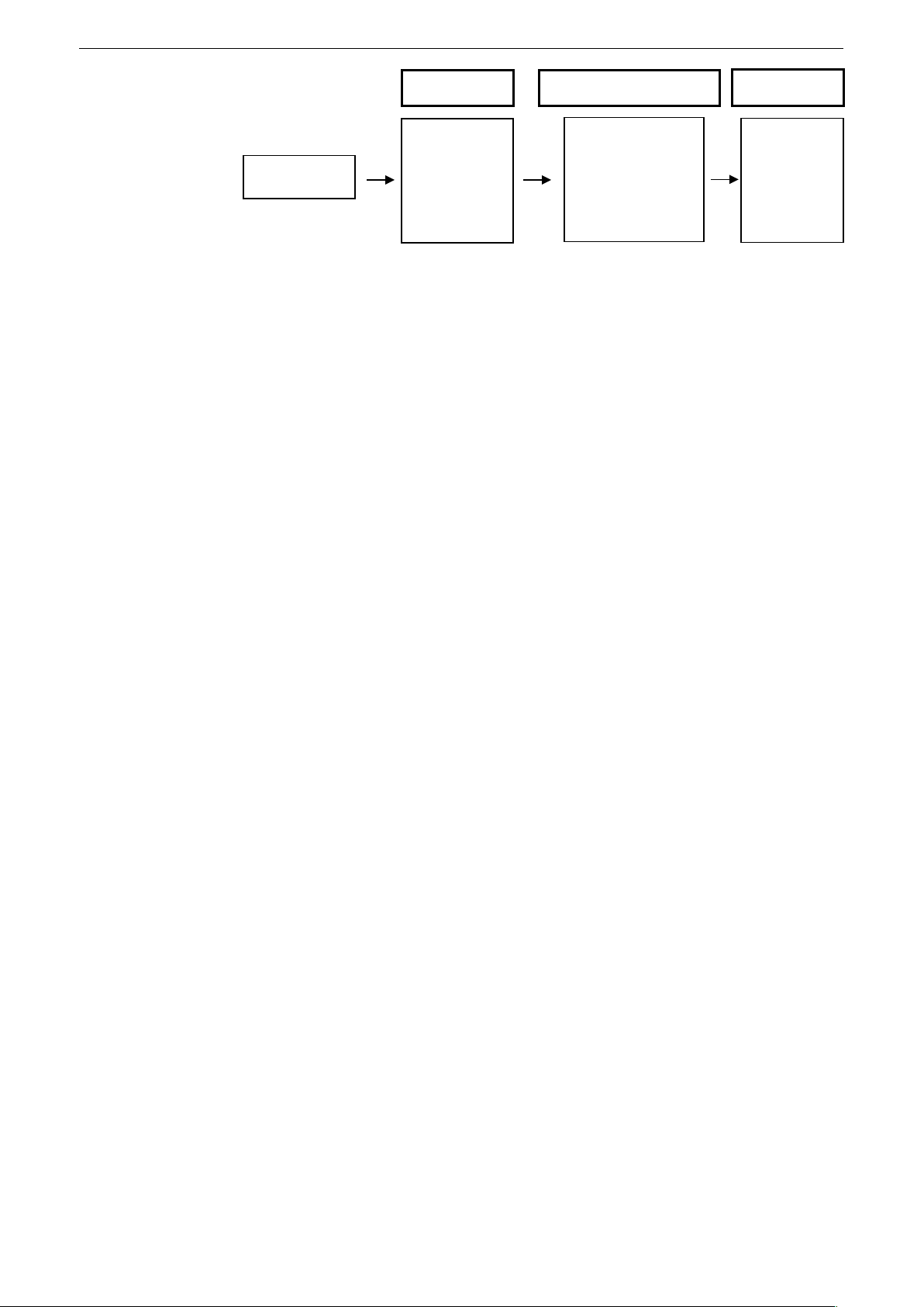
11. CONTENTS OF DELIVERY / SPECIFICATION
11.1 Contents of delivery
Depending on ordering code:
Alarm unit: EA-8-DPX, EA-8-DPXN, EA-8-DPXM, DPXF, DPXFN or DPXFM
Voice announcement: German, French, English, Italian. Other languages on request.
Sub-communication unit: LMC70 Art. No: 118.0155
LMK70C Art. No: 118.0160
LMK70C-WG Art. No: 118.0161 water resistant IP54
LMK70T-LOOP Art. No: 118.0165 Set: LMK70T + Hearing aid loop
LMK70T-EXC Art. No: 118.0166 Set: LMK70T + Exciter :
LMK70-ATEX 0 Art. No: 121.0370 LMK70-ATEX Zone 0 + Art. No: 121.0390 ATEX-Barrier
LMK70-ATEX 20 Art. No: 121.0380 LMK70-ATEX Zone 20 + Art. No: 121.0390 ATEX-Barrier
Accessory: SNEL Art. No: 100.0277
EA-NT-IN Art. No: 100.0250
EA-DCDC Art. No: 100.0290 Supply from 8 to 35 V DC in battery compartment
Cables: Standard 3 m (other length on request 0.5 m, 1.5 m, 5 m)
11.2 Specification
Changes to product and performance can be made at any time without announcement..
11.2.1 Alarm units EasyAlarm® EA-8-DPX (Art. No: 101.0220)
Primary voltage: 9 to 16 V DC (over EXT/≂ jack)
Backup: 9 V-Battery (Alkaline: Typical 70 hours)
Emergency operation: Alarm with telephone line powering.
Consumption: Standby: 7 mA (typical)/during announcement up to 80 mA
Housing material: ABS
Dimension: 200 x 110 x 31 mm (L x Ex H)
Weight: 320 g without battery
Telephone cable: RJ12 3 m incl. (other length on request 0.5 m, 1.5 m, 5 m)
on request (RJ12 to country specific telephone adapter)
Dialling: DTMF (Touch-tone)
11.2.2 Alarm units EasyAlarm® EA-8-DPXN (Art. No: 101.0230)
Same as EA-8-DPX with additional telephone output:
Downstream telephone/modem will be disconnected in case the alarm unit has to dial out.
Downstream telephone/modem is connected to the PSTN if the alarm unit is in standby mode.
11.2.3 Alarm units EasyAlarm® EA-8-DPXM (Art. No: 101.0260)
Same as EA-8-DPX with integrated machine room interface 6.10
If the machine room telephone is off-hook you get instant hands-free communication into the cabin. A external line (to
PSTN) can be selected by sending touch-tone 0.
The telephone/modem will be disconnected in case the alarm unit has to dial out.
Consumption: Standby: 20 mA (typical)/during announcement up to 100 mA
11.2.4 Alarm units EasyAlarm® EA-8-DPXF (Art. No: 101.0240)
Same as EA-8-DPX but incl. serial interface to communicate with a Liftronic elevator control. Sensor-3 not usable.
Primary voltage: 9 to 16 V DC (over Liftronic-Interface)
11.2.5 Alarm units EasyAlarm® EA-8-DPXFN (Art. No: 101.0243)
Same as EA-8-DPX with additional telephone output:
Downstream telephone/modem will be disconnected in case the alarm unit has to dial out.
Downstream telephone/modem is connected to the PSTN if the alarm unit is in standby mode.
11.2.6 Alarm units EEasyAlarm® EA-8-DPXFM (Art. No: 101.0246)
Same as EA-8-DPXF but with integrated machine room interface: 6.10.
33
EA8
DPX
DPXN
DPXM
DPXF
DPXFN
DPXFM
Alarm unit Sub-communication unit
SNEL
EA-NT-IN
EA-DCDC
Accessory
LMC70
LMK70C
LMK70C-WG
LMK70T-LOOP
LMK70T-EXC
LKM70-ATEX 0/20
Page 36

12. WARRANTY
Dear customer
Each EasyAlarm® is manufactured and tested according to stringent quality rules. If the unlikely case should happen, that
due to a manufacturing error the product is malfunctioning, Leitronic AG will guarantee in addition to your sales distributor
warranty of repairs without any labour or material costs for 2 years after date of purchase.
Warranty is only granted, if the unit has been used as described in the instruction manual.
Warranty will not be given under following circumstances:
If there is no invoice or receipt with date of purchase, vendor’s name and serial number.
These documents have been changed or modified.
If serial number on type label has been changed, cleared, removed or modified in any way.
If any repair, modification or other adaptation has been carried out by an unauthorized person or company.
Damage due to tampering with device.
Damage due to external influence (lightning, water, fire and so on).
Please contact Info-Line +41 (0)56 648 40 40 before sending out units because normally there are no faulty units but
misinterpretation of the behaviour or programming errors!
Leitronic AG
Engeloostr. 16
CH-5621 Zufikon
Tel. +41 (0)56 648 40 40
www.easyalarm.ch
SCHAEFER GmbH
Elektrotechnik + Maschinenbau
Postfach 30 01 67
D-72488 Sigmaringen-Laiz
Tel +49 (0)7571 722-51
www.ws-schaefer.de
[email protected]
34
Page 37
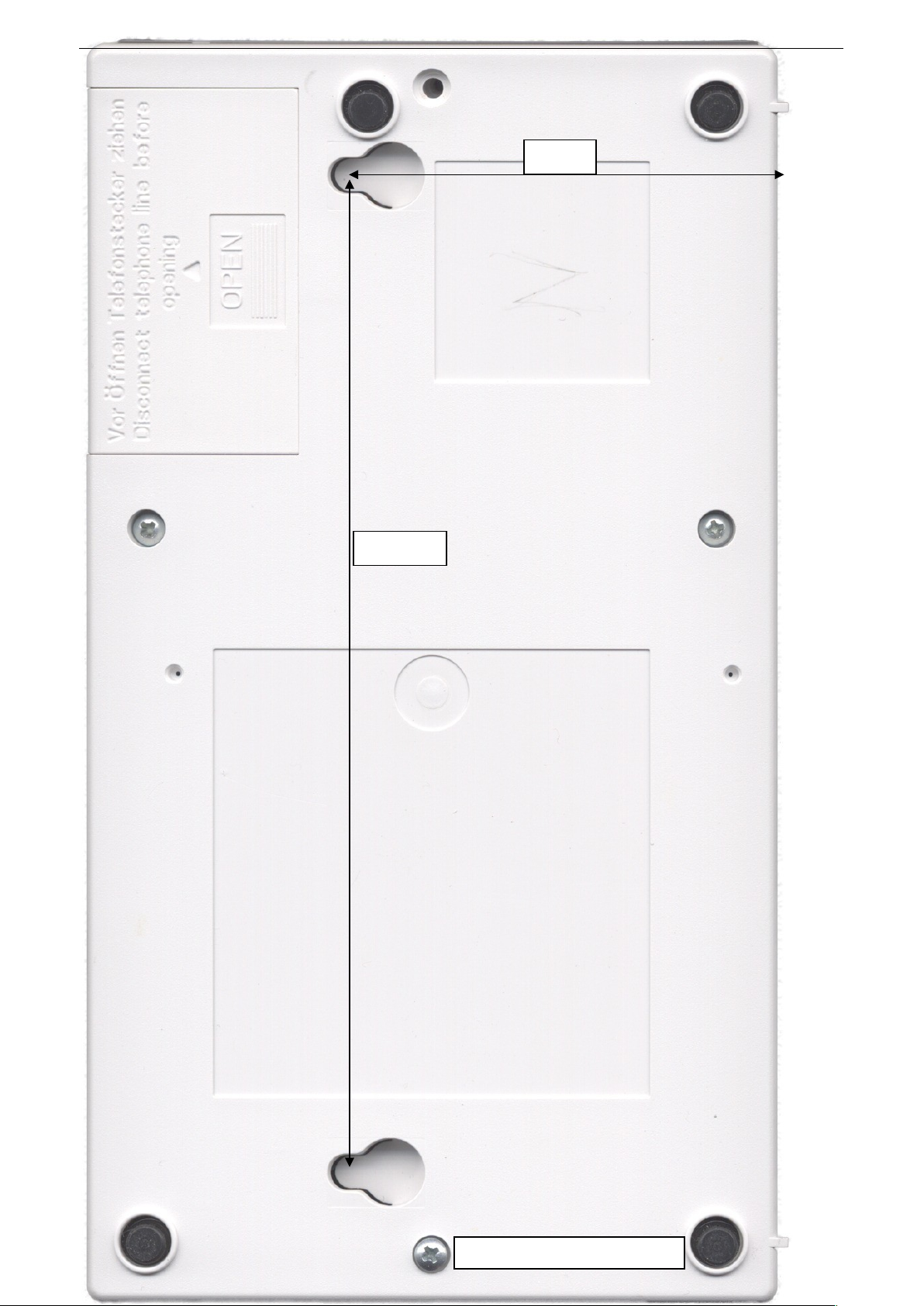
Overall dimension 110 x 200 mm
69 mm
158 mm
13. DRILLING PATTERN
35
Page 38

14. INDEX
Accessory.........................................................5, 6, 8, 28, 30
Acknowledgement (Alarm)..........................................15f, 25
Alarm
Acknowledge...........................................................15, 16
Calling numbers
how to program .......................................10, 11, 15, 32
Dialling delay.......................................................10, 18
Calling number sequence..................................11, 14, 15
Repetitions...............................................................16, 25
Alarm contact.........................................................3, 4, 8, 28
Announcement ..........................................10, 15, 20, 22, 26
Approval.......................................................................Cover
Assembly .........................................................................5, 6
Battery change..................................................................21
BackGroundNoise-Filter.....................................................29
Building control system (LMK-OUT).........................9, 15, 29
Call-Center solution......................................................14, 32
Communication test.............................10, 14, 20, 25, 29, 32
Communication units.........2, 4, 5, 6, 8, 9, 16, 23, 30, 31, 33
Connection
Dial-up.........................................................15, 22, 25, 26
Time-out...................................................................15, 26
Configuration........................................................8, 9, 28, 29
Contact configuration............................................27, 28, 29.
Connectors...........................................................3, 4, 7, 8, 9
Dialling-in ............................................16, 17, 20, 23, 26, 27
access ...............................................................17, 18, 27
DIN-Adapter EA-ACDC-xxx...........................................9, 30
Direct call / Test call............................................................16
Door contact ..........................3f., 7, 9, 14, 18, 19, 20, 24, 28
Drilling pattern................................................................6, 35
DTMF.......................................................................3, 20, 22
commands ....................................................................15
Emergency operation ............................2f., 9, 10, 20, 24, 28
Slide switch / Jumper ....................................................28
Emergency light ................................................5, 18, 19, 31
Emergency button...................3, 4, 5, 8, 10, 14, 16, 20ff., 28
Response.......................................................................28
Error handling.....................................................................22
Exciter (LMK70T).................................................4, 9, 16, 30
Factory setting........................................... 25, 26, 27, 28, 29
Fire brigade EN81-72...................................................19, 32
Gateway / UMTS / GMS / LTE.....................2, 18, 19, 29, 31
Hands-free communication................................................16
Volume...........................................................4, 16, 23, 29
Quality....................................................................5, 7, 23
Hands-free.............................3f., 9f., 12f., 16, 18f., 22f., 26f.
Communication..............................3f., 10, 16, 18, 23, 26f.
Hearing-aid-loop (LMK70T)..................................4, 9, 16, 30
Hotline-Mode......................................................................10
Individual announcement ......................................12, 15, 26
Installation............................................................................7
Lamps.............................................3f., 6, 13, 15, 17, 22, 30f
LED ..................................................................3f., 6, 15, 30f
Light pipes........................................................................4, 6
Lock programming........................................................11, 22
Machine room communication ...................18,19, 29, 30, 31
Microphone............................................................3, 4, 5, 16
Misuse-protection.................................3, 7, 9, 14, 20, 24, 26
adjust cabin travel time .................................................27
Modem...........................................................3, 7, 17, 18, 27
Outputs.......................................................3, 4, 9, 15, 20, 29
Panels / Frames...............................................................5, 6
PIN-Code.............................................12, 15, 17, 20, 23, 27
How to program ......................................................12, 32
Point-ID..................................................................10, 22, 31
Power failure .................................................2, 9, 14, 20, 23
Alarm due to................................................13, 14, 18, 25
Programming
Announcements.............................................................12
unlock............................................................................12
PIN-Code.................................................................12, 32
Calling number.............................................10, 11, 15, 32
Calling number sequence..................................11, 14, 15
Emergency button contact type...........................8, 24, 28
factory settings...............................................................25
Protocol........................................................................10, 31
Routine call..........................................10, 14, 16, 20, 25, 32
Remote access......................................2, 17, 22, 23, 26, 27
Remote-Programming......................................11, 12, 20, 27
Remote-communication / Fire brigade EN81-72..........19, 32
Retrofitting..............................................................5, 6, 8, 30
Ringing cycles (dialling-in) ........................15, 17, 22, 23, 26
Routine call....................4, 10, 13, 14, 16, 20, 21, 22, 25, 32
Safety notes.........................................................................2
Schema (Overview)......................................................Cover
Select user language...................................................12, 15
Selection switch...............................................3, 7, 9, 13, 24
Sensor-1 (Misuse)......................3, 4, 7, 9, 10, 14, 20, 24, 27
Sensor-2 (Emergency button)....................3, 4, 9, 10, 24, 28
Sensor-3 (Technical Alarm)..............3, 4, 8, 9, 10, 14, 24, 28
Short instruction............................................................Cover
Speaker........................................................3, 4, 16f., 23, 28
Sub-communication units.............4, 5, 6, 8, 9, 16, 23, 30, 31
Supervision ...............................3, 13, 14, 15, 20, 24, 27, 29
Supply ...................................................2, 3, 4, 9, 20, 23, 30
Switch
Function.......................................................................3, 9
Selection......................................................................3, 9
Emergency button contact type (in battery compart.)....28
Symbol lamps (EN81-70).................4, 5, 6, 9, 14, 15, 17, 29
Telephone line........................................2f., 7, 18, 19, 20, 22
suitable / unsuitable........................................................ 2
Test.............................................................................7, 9, 24
Telephone line............................................................7, 22
Sensor wiring.............................................................9, 24
Test call..............................................................................16
Touch tone / DTMF...................................................3, 20, 22
commands ....................................................................15
Unlock programming....................................................11, 22
UPS................................................................................9, 30
User announcements.......................................10, 15, 22, 26
User language..............................................................12, 15
VoIP (Voice over IP).............................................................2
Volume of the hands-free communication..............16, 23, 29
Waiting period..............................................................13, 17
Warranty ............................................................................34
WinMOS®)300 (Call-Centre-Solution).........................14, 32
Wiring
Installation................................................................7, 8, 9
testing....................................................................7, 9, 24
Overview..................................................................Cover
36
Page 39
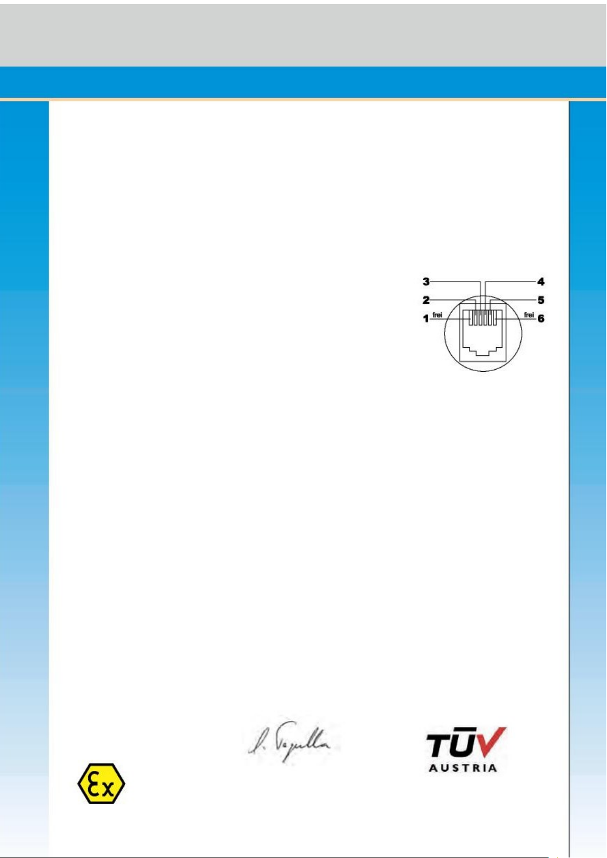
Manufacturer’s Name: Leitronic AG
Manufacturer’s Address: Engeloostrasse 16
CH-5621 Zufikon
Switzerland
declares that the product
Product Name: EasyAlarm
a b
Model Number: EA-8-DPXN / EA-8-DPXM
EA-8-DPXF / EA-8-DPXFM
We herewith declare that the components supplied under the
aforementioned order number meet the following EC Directives
EMC: 2014/30/EU
RoHS 2: 2011/65/EU
Standards applied
Safety (Article 3.1a): EN 60950-1:2006+A11:2009
+A1:2010+A12:2011
EMC (Article 3.1b): EN 12015:2014
EN 12016:2013
Safety rules for the construction and installation of lifts EN81-28:2018
- Lifts for the transport of persons and goods
Part 28: Remote alarm on passenger and goods passenger lifts
Safety rules for the construction and installations of lifts EN81-70:2017
– Particular applications for passenger and goods passenger lifts
– Part 70: Accessibility to lifts for persons including persons with disability;
Safety rules for the construction and installation of lifts EN81-72:2015
- Particular applications for passenger and goods passengers lift
- Part 72: Firefigthers lift
Supplementary Information
The product herewith complies with the requirements of the following Directives and carries the CE marking
accordingly 2014/30/EU:
Zufikon, 13.2.2019
Silvan Tognella
TÜV-Austria, 30.4.2010
Berichtsnummer: AT-08/0023
Declaration of conformity
Page 40
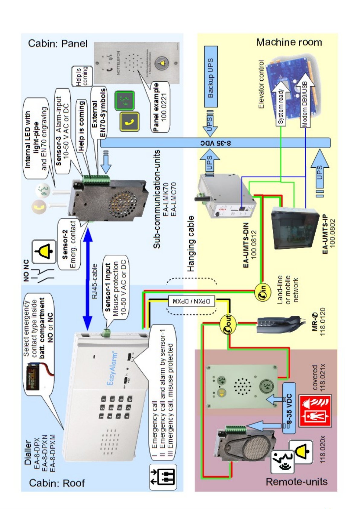
Installation
 Loading...