

Leica DISTOTM X4
The original laser distance meter

Overview 2
Technical data 4
Instrument Set-up 6
Settings 10
Operations 27
Message Codes 53
Care 54
Warranty 55
Safety instructions 56
Leica DISTO™ X4
1
Overview
Overview
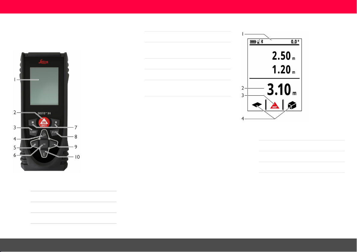
Components
The Leica DISTO™ isa laser distance meter operating with a class 2 laser. See chapter Technical
data for scope of use.
5Add/ Navigate left
6Enter/ Equal
7Selection keys linked to symbols
above
8Functions
9Subtract/ Navigate right
10Measuring reference/ Navigate
downwar ds
Basic result screen
1Status bar
2Main line
3Active function
4Favorites
1Display
2ON/ Measure
3Clear/ OFF
4Zoom/ Navigate upwards
Leica DISTO™ X4
2
Overview
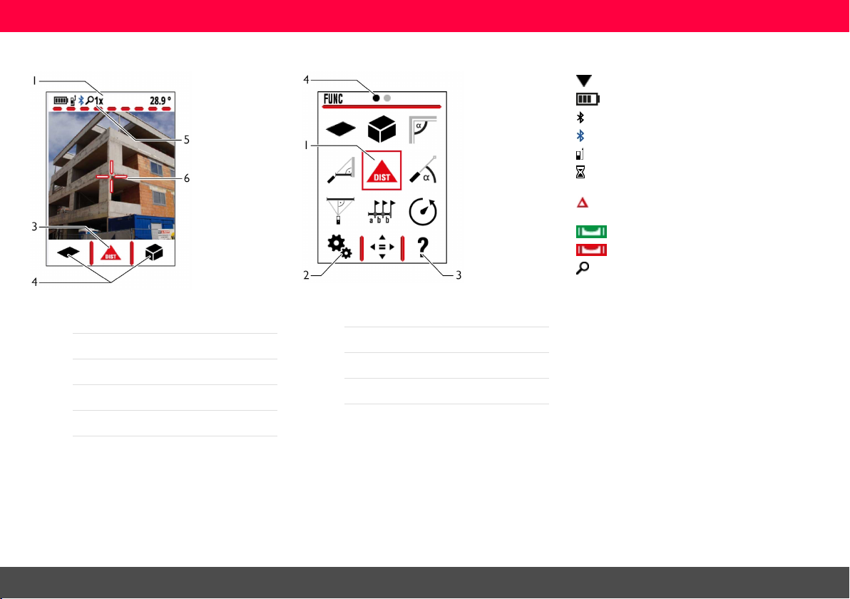
Basic measuring screen
1Status bar
3Active function
4Favorites
5Zoom stage
6Cross hair
Selection screen
1Function/ Settings
2Settings
3Help function
4Page indicator
Icons on status bar
Scrolldown for further results
Battery power
Bluetooth® isswitched on
Bluetooth® connectionestablished
Measuring reference
Device is measuring
Offset is activated and adds/substracts
the defined value from measuring distance
Device is levelled
Device is not levelled
Zoom
Leica DISTO™ X4
3

Technical data
Tech nicaldata
General
Accuracywith favourable conditions * 1 mm / 0.04" ***
Accuracywith unfavourable conditions** 2 mm / 0.08" ***
Range with favourable conditions* 0.05 - 150m / 0.16 - 500ft ***
Range with unfavourable conditions ** 0.05 - 80m / 0.16 - 260ft ***
Smallest unit displayed 0.1 mm / 1/32 in
X-Range Power Technology yes
Laser class 2
Laser type 635 nm, <1 mW
ø laser point | at distances 6 /30 /60 mm | 10/ 50/ 100 m
Tilt measuring tolerance to laser beam **** ± 0.2°
Tilt measuring tolerance to housing **** ± 0.2°
Tilt measuring range **** 360°
Protection class IP65 (dust- and splash water protected)
Auto. laser switch off after 90 s
Auto. power switch off after 180 s
Bluetooth® Smart Bluetooth® v4.0
Power of Bluetooth® Smart 0.71 mW
Frequency of Bluetooth® Smart 2400 - 2483.5 MHz
Range of Bluetooth® Smart <10m
Battery durability(2 x AA) up to 4000 measurements
Dimension (H x D x W) 132 x 56 x 29 mm | 5.2 x 2.2 x 1.1 in
Weight ( with batteries) 184 g/ 6.49 oz
Temperature range Storage | Operation -25 to 70°C/ -13 to 158°F | -10 to 50°C/ 14 to 122°F
* favourable conditions are: white anddiffuse reflectingtarget (w hite painted wall), low background illu-
minationand moderate temperatures.
** unfavourable conditions are:targets w ith lower or higher reflectivity or high background illumination or
temperatures at the upper or l ower end of thespecified temperature range.
*** Tolerances apply from 0.05 m to 10 m with a confidencelevel of 95%.
With favourable conditions the tolerancem ay deteriorate by 0.10 m m/m for distances above 10 m.
Leica DISTO™ X4
With unfavourable conditions the tolerancem ay deteriorate by 0.15 m m/m for distances above 10 m.
**** after user calibration. Additional angle r elated deviation of +/-0.01° per degree up to +/-45° in each quad-
rant.
Applies at room temperature. For the whole operating temperature range the maximum deviation
increases by +/-0.1°.
4

Technical data
Func tions
Distance measuring yes
Min/Max measuring yes
Permanent measuring yes
Stake out yes
Addition/Subtraction yes
Area yes
Room angle yes
Volume yes
Painter function (area with partial measurem.) yes
Pythagoras 3-point
Smart Horizontal Mode / Indirect height yes
Level yes
Memory yes
Beep yes
Illuminated colour display yes
Bluetooth® Smart yes
Personalized Favorites yes
Timer yes
Point to point function/ distance yes *****
Smart Area yes *****
Height tracking yes
***** In combination w ith Leica DST 360 adapter
Leica DISTO™ X4
5
Instrument Set-up
InstrumentSet-up
Introduction
The safety instructions (see Safety
Instructions) and the user manual
should be read through carefully
before the product isused for the first
time.
The person responsible for the
product must ensure that all users
understand these directions and
adhere to them.
The symbols used have the following
meanings:
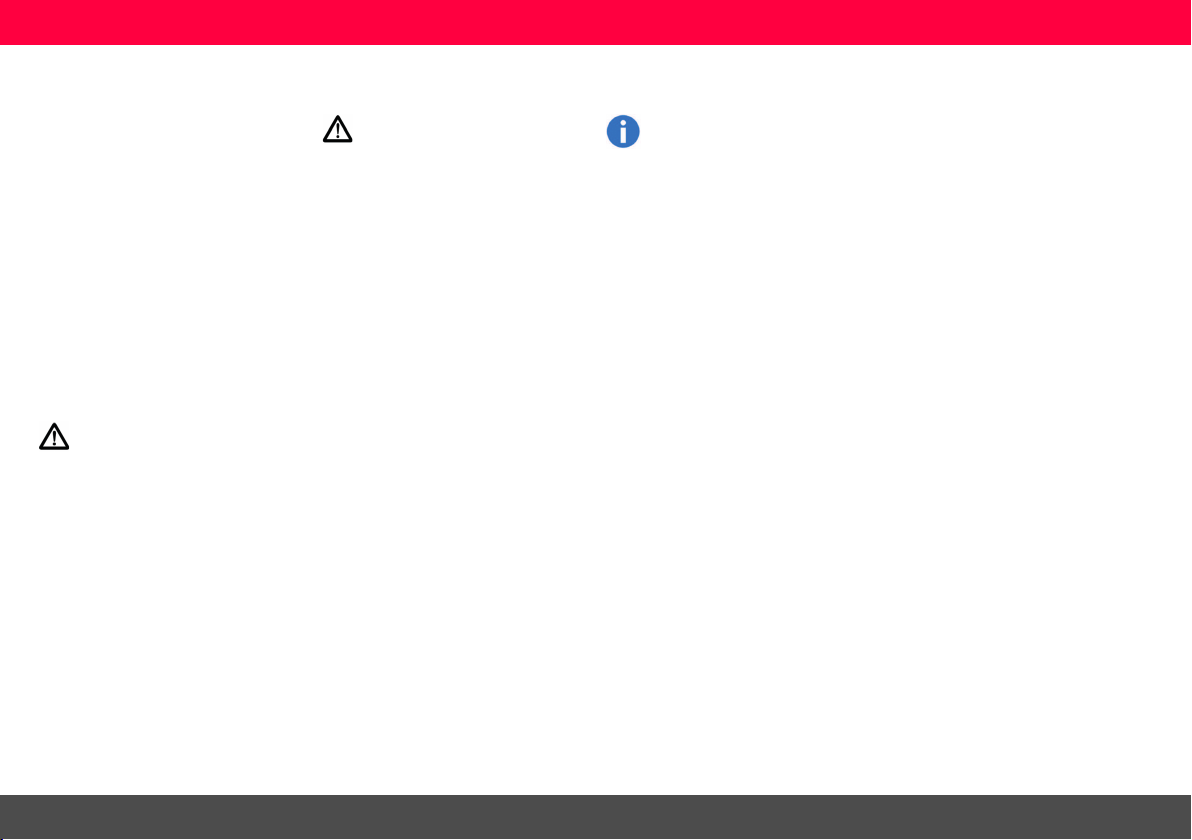
WARNING
Indicatesa potentiallyhazardous situation or an unintended use which, if
not avoided, willr esult in death or serious injury.
CAUTION
Indicatesa potentiallyhazardous situation or an unintended use which, if
not avoided, may result in minor injury
and/or appreciable material, financial
and environmental damage.
Important paragraphs which
must be adhered to in practice
as they enable the product to be
used in a technically correct and
efficient manner.
Leica DISTO™ X4
6
Instrument Set-up
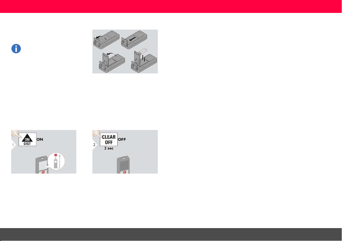
Insert batteries
To ensure a reliable use, we
recommend using high quality
Alkaline batteries. Change batteries when battery symbol is
flashing.
Switching ON/OFF
Leica DISTO™ X4
Device is tur ned OFF.
7
Instrument Set-up
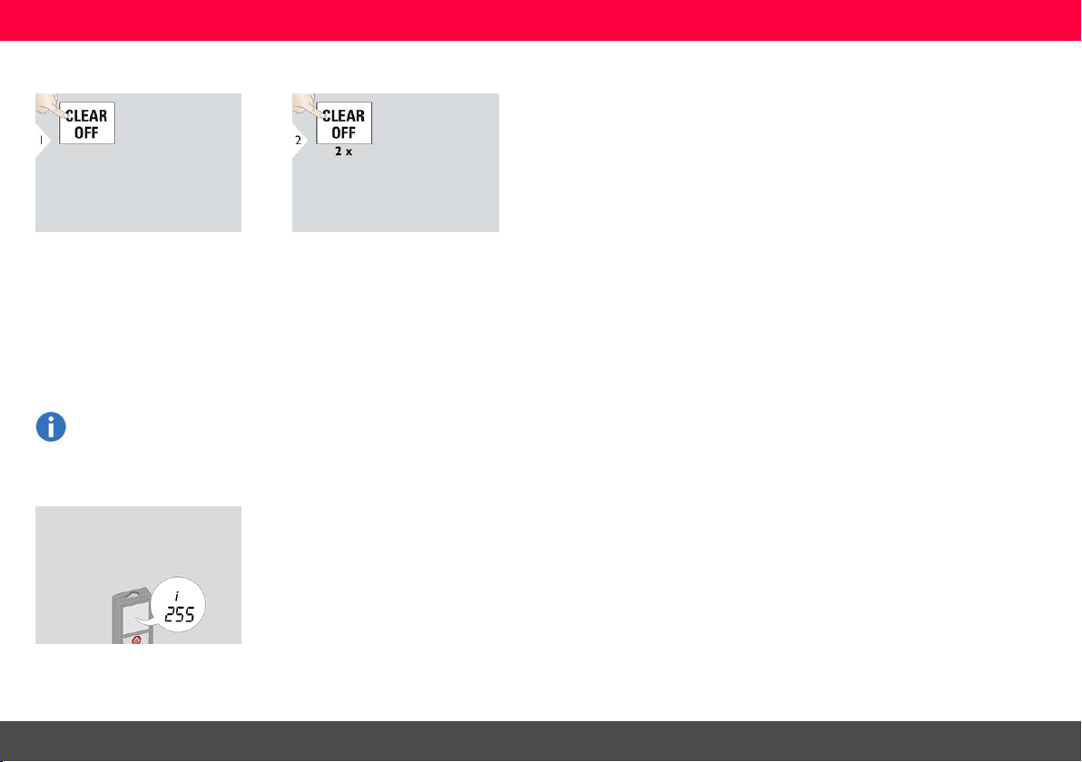
Clear
Undo last action. Leave actualfunction, go to default
operation mode.
Message Codes
If the message "i" appears with
a number, observe the instructions in Message Codes section.
Example:
Leica DISTO™ X4
8
Instrument Set-up
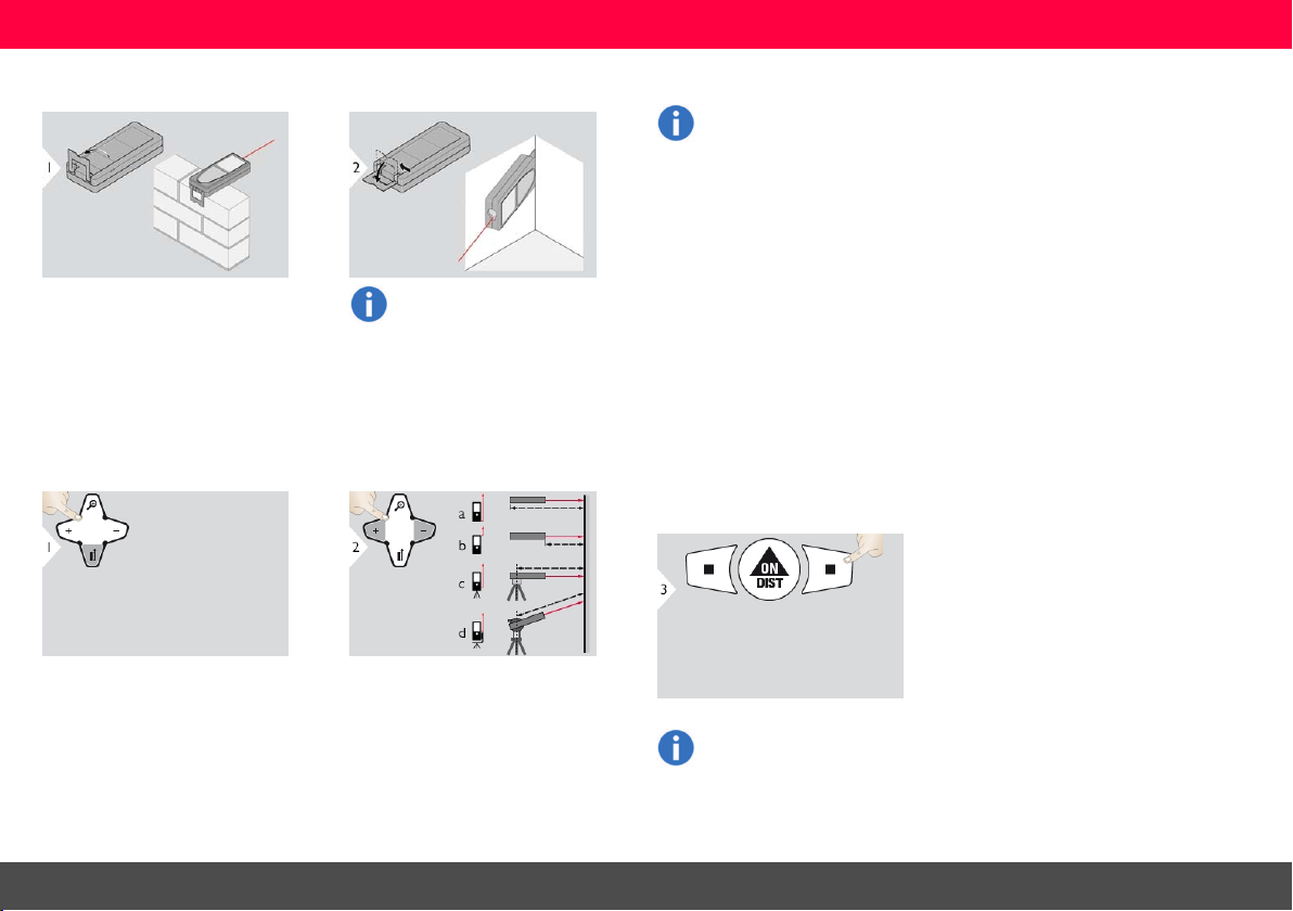
Multifunctional endpiece
When measuring with 90°
flipped-out endpiece please
meake sure that it lies plane
against the edge you measure
from.
The orientation of the endpiece
isautomaticallydetected and
the zero point isadjusted accordingly.
Adjusting measuring reference
Leica DISTO™ X4
a) Distance ismeasured from the
rear of the device (standard setting).
b) Distance ismeasured from the
front of the device.
c) Distance is measured from the tripod thread.
d) Distance ismeasured from a Leica
DISTO Adapter F TA 360.
Confirm setting.
If device isswitched off, reference goes back to standard
setting (rear of the device).
9
Settings
Settings
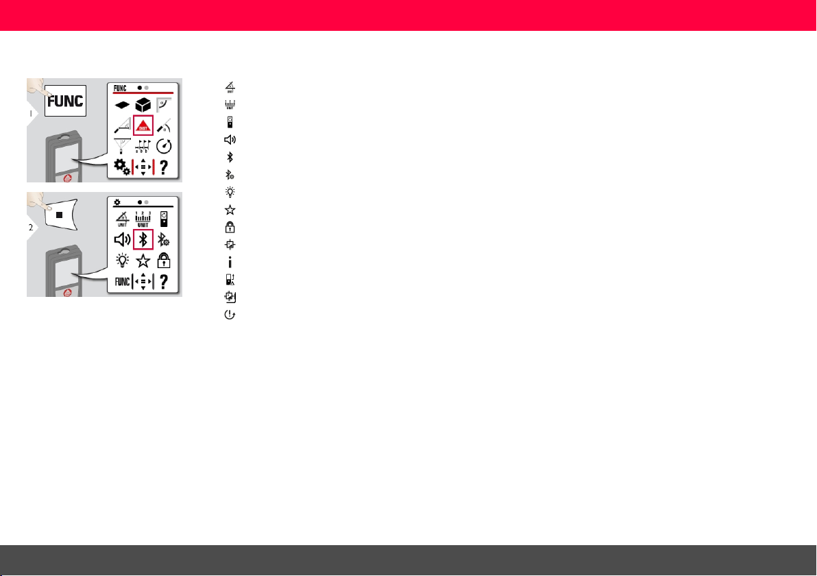
Overview
Tilt units
Distance units
Turning screen**
Beep
Bluetooth®
Bluetooth® settings
Illumination
Favorites
Keypad lock
Tilt calibration
Information / Serial number
Offset
Calibration of DST 360*
Reset
* Activatedwhenconnected to Leica DST 360
adapter
** F irmware update mi ght be requiredthrough the
Leica DISTO™PlanAppto getthis feature
Leica DISTO™ X4
10
Settings
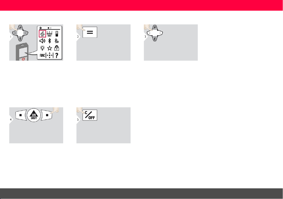
Tilt units
Switch between the following units:
360.0°
0.00 %
Confirm setting. Exitsettings.
Leica DISTO™ X4
11

Settings
Distance units
Switch between the following units:
0.00 m
0.00 ft
0.000 m
0.000 in
0.0000 m
0'00" 1/32
0.0 mm
0 in 1/32
Confirm setting. Exitsettings.
Leica DISTO™ X4
12
Settings
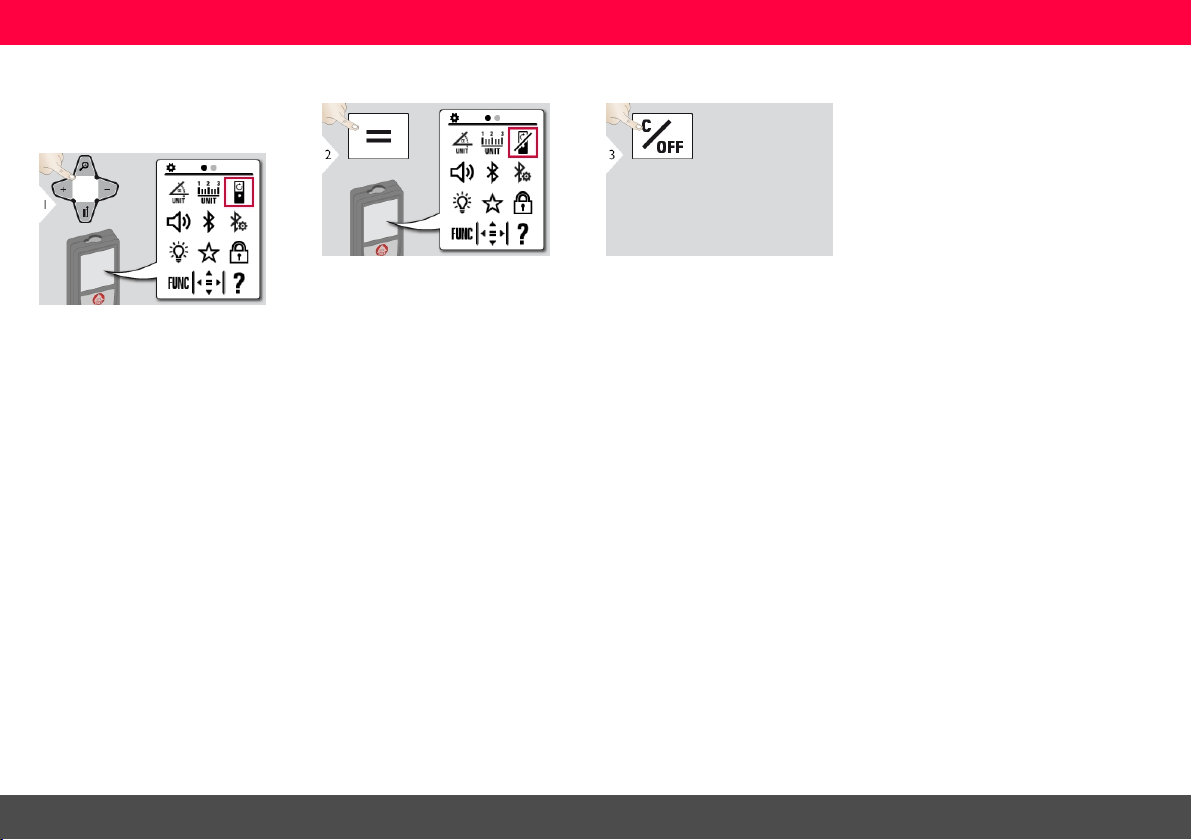
Turning screen ON/OFF*
* Firmware update might be required through the
Leica DISTO™PlanAppto getthis feature
To switch ON, repeat procedure. Exitsettings.
Leica DISTO™ X4
13

Settings
Beep ON/OFF
To switch ON, repeat procedure. Exitsettings.
Leica DISTO™ X4
14
Settings
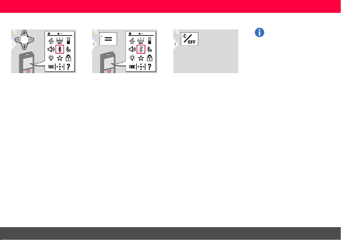
Bluetooth® ON/OFF
Bluetooth® isswitched on and
blackBluetooth® icon is displayed in status bar . If connection is established the color
of the icon changes to blue.
To switch ON, repeat procedure. Exitsettings.
Leica DISTO™ X4
15
Settings
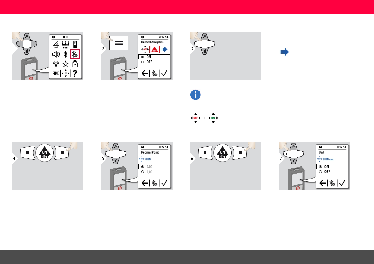
Bluetooth® Settings
Confirm setting. Select kind of decimalpoint for trans-
mitted value.
If activated in measuring mode, it
allowsthe arr ow keys to move the
cursor on your computer.
Short press: send the value of the
main line to your computer.
Long press: send allmeasurements
and results to your computer .
Select ON or OFF .
If device isconnected, the favorites disappear and two softkeys
appear:
Confirm setting. Select if unit is transmitted or not.
Leica DISTO™ X4
16
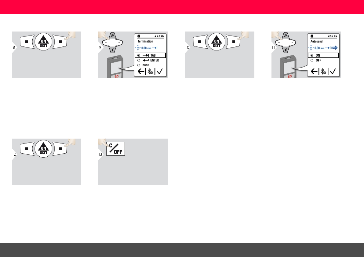
Settings
Confirm setting. Select termination of transmission. Confirm setting. Select if value is transmitted auto-
matically or manually.
Confirm setting. Exitsettings.
Leica DISTO™ X4
17

Settings
Illumination
Select brightness. Confirm setting.
Exitsettings.
To save power reduce brightness if not necessary.
Leica DISTO™ X4
18

Settings
Personalized favorites
Exitsettings.
Leica DISTO™ X4
Select favorite function. Press selection key left or right. Func-
tion is set as favorite above the corresponding selection key.
Select your favorite functions for
quickaccess.
Short cut:
Press 2 sec on a selection-key in
the measuring mode. Select
your favorite function and press
again short on the corresponding selection key.
19

Settings
De-/Activate keylock
Leica DISTO™ X4
To deactivate, r epeat procedure. The
keylock is active if device isswitched
off.
Exitsettings.
20

Settings
Calibration of tilt sensor (Tilt Calibration)
Placedevice on absolutely flat surface.
Turn the device horizontallyby 180°
and place it again on absolutely flat
surface.
Leica DISTO™ X4
Placedevice on absolutely flat surface.
21

Settings
Turn the device horizontallyby 180°
and place it again on absolutely flat
surface.
Leica DISTO™ X4
After 2 sec the device goes back
to the basicmode.
22

Settings
Information
Exitinformation screen. Exit settings.
Leica DISTO™ X4
23

Settings
Offset
Select digit. Adjust digit.
Approve value. Exitsettings.
An offset adds or subtracts a
specified value automatically to
or from allmeasurements. This
function allows tolerances to be
taken into account. The offset
icon is displayed.
Leica DISTO™ X4
24

Settings
Calibration of Leica DST 360 adapter*
* Function is activated when connected to theLeica
DST 360 adapter.
Define a point to be measured in a distance more than 8 m. Aim at defined
point and press DIST button to start
the 5 secondscountdown to measure.
Turn the device vertically by 180°. Turn the device by 180°. Aim again at
defined point and pr ess DIST button
to start the 5 seconds countdown to
measure.
Leica DISTO™ X4
Get more accurate results of the
device in combination with the
Leica DST 360 adapter.
25

Settings
Reset
Reset returns the instrument to
the factory settings. Allcustomized settings and memories
are lost.
Second confirmation with selection
keys:
a) Refuse
b) Confirm
Leica DISTO™ X4
26

Operations
Operations
Overview
Singledistance measurement
Area
Volume
Room angle
Smart Horizontal Mode
Level
Pythagoras (3-point)
Stake out
Timer
Height tracking**
Memory
Point to point measurement*
Point to point measurement lev-
elled*
Smart area measurement*/**
* Activatedwhenconnected to Leica DST 360
adapter
** F irmware update mi ght be requiredthrough the
Leica DISTO™PlanAppto getthis feature
Leica DISTO™ X4
27

Operations
Pointfinder
This is a great help for outdoor
measuring. The integrated pointfinder (viewscreen) shows the
target on the display. The device
measures in the middle of the
cross hair, even if the laser dot is
not visible.
Parallax errors occur when the
pointfinder camera is used on
close targets, with the effect that
the laser appears displaced in
the crosshair. In thiscase rely on
the real laser dot. When using
the point to point functions and
smart area measurement the
error is automatically corrected
with a shift of the crosshair.
The pointfinder is always on,
when the laser beam is on.
Leica DISTO™ X4
28

Operations
Measuring single distance
Target surfaces: Measuring
errors can occur when measuring to colourlessliquids, glass,
styrofoam or permeable surfaces or when aiming at high
glosssurfaces. Against dark surfaces the measuring time
increases.
Aim active laser at target.
Leica DISTO™ X4
29

Operations
Permanent / Minimum-Maximum measuring
Use Down navigation key to
take over valuesin the main line
for sending via Bluetooth®
Smart.
Leica DISTO™ X4
Used to measure room diagonals
(maximum values) or horizontaldistance (minimum values).
The minimum and maximum distance
measured is displayed (min, max.).
The last value measured is displayed
in the main line.
Stops permanent / minimum-maximum measuring.
30

Operations
Add / Subtract
Leica DISTO™ X4
The next measurement isadded to
the previous one, respectively subtracted from the previous one.
This process can be repeated
as required. The same process
can be used for adding or subtracting areas or volumes.
31

Operations
Area
The area is calculated based on the
mathematic term multiplying 2 distances.
Leica DISTO™ X4
Aim laser at second target point. a) First distance
b) Second distance
c) Circumference
d) Area
Aim laser at first target point.
The result is shown in the main
lineand the measured value
above. Painter function: Press +
or - after starting the first measurement. Measure and add or
subtract wall lengths. Measure
finally height for second length
to get the wall area.
Use Down navigation key to
take over valuesin the main line
for sending via Bluetooth®
Smart.
32

Operations
Volume
The volume iscalculated based on
the mathematic term multiplying 3 distances.
Leica DISTO™ X4
Aim laser at first target point.
Aim laser at second target point. Aim laser at third target point.
33

Operations
Use Down navigation key to
show more resultsor to take
over valuesin the main line for
sending via Bluetooth® Smart.
a) First distance
b) Second distance
c) Third distance
d) Volume
Leica DISTO™ X4
a) Ceiling/floor area
b) Wall areas
c) Circumference
34

Operations
Room angle
The angle is calculated based on the
cosine rule with 3 known side lengths
of a triangle.
Leica DISTO™ X4
Aim laser at first target point.
Aim laser at second target point. Aim laser at third target point.
35

Operations
Use Down navigation key to
show more resultsor to take
over valuesin the main line for
sending via Bluetooth® Smart.
a) First distance
b) Second distance
c) Third distance
d) Angle between first and second
measurement
Leica DISTO™ X4
a) Circumference
b) Tr iangular area
36

Operations
Smart Horizontal Mode
The horizontaldistance is calculated
based on the trigonimetric function
cosine with 1 known length and 1
known angle.
Use Down navigation key to
take over valuesin the main line
for sending via Bluetooth®
Smart.
Leica DISTO™ X4
Aim laser at target (up to 360° and a
transverse tilt of ±10°).
37

Operations
Level
Displays inclinations of 360°.
Instrument beeps at 0° and 90°.
Ideal for horizontal or vertical
adjustments.
Leica DISTO™ X4
38

Operations
Pythagoras (3-point)
The distance is calculated based on
the Pythagorean theorem with 3
known lengths of 2 right-angled triangles.
Leica DISTO™ X4
Aim laser at first target.
Aim laser at second target. Aim laser at third target.
39

Operations
The result is shown in the main
lineand the measured distance
above. Pressingthe measuring
key for 2 sec in the function activates automatically Minimum or
Maximum measurement.
We recommend to use the
pythagoras only for indirect horizontal measuring. For height
measuring (vertical) it is more
precise to use a function with
inclination measurement.
Use Down navigation key to
take over valuesin the main line
for sending via Bluetooth®
Smart.
Leica DISTO™ X4
40

Operations
Stake out
Two different distances(a and
b) can be entered to mar k off
defined measured lengths.
Select digit. Adjust digit. Approve value "a". Adjust value "b".
Leica DISTO™ X4
41

Operations
Approve value "b" and start measurement.
When approaching a stake out
point to less than 18 mm the
value of the stake out point is
frozen and the arr ows on the
side change their colour to red
for marking purposes.
Leica DISTO™ X4
Move device slowly along the stake
out line. The distanceto the next
stake out point is displayed.
The function can be stopped by
pressing the CLEAR/OFF button.
a) Distance to first stake out point
b) Actual position to measured target
c) Distance to second stake out point
42

Operations
Timer
Select release time. Confirm setting.
The self release starts if
ON/Measure key ispressed.
Leica DISTO™ X4
43

Operations
Height tracking*
* Firmware update might be required through the
Leica DISTO™PlanAppto getthis feature.
The height is calculated based on trigonimetric functionswith 1 known
length and 1 measured angle.
Aim laser at lower point.
Aim laser at upper points and
angle/height tracking starts automatically.
Leica DISTO™ X4
Stops height tracking.
44

Operations
Heights of buildings or trees
without suitable reflectivepoints
can be determined. At the bottom point, distance and tiltis
measured - which needs a
reflectivelaser target. The
upper point can be targeted with
the pointfinder / crosshair and
does not need a reflective laser
target as only the inclination is
measured.
Use Down navigation key to
show more resultsor to take
over valuesin the main line for
sending via Bluetooth® Smart.
Leica DISTO™ X4
45

Operations
Memory (last 20 results)
Leica DISTO™ X4
a) Delete memory
b) Take over value for further actions
Use Down navigation key to show
more detailed results of the specific
measurement.
Use Left/Right navigation keys to
switch between measurements.
46

Operations
Point to point measurement*
* Function is activated when connected to theLeica
DST 360 adapter.
The tie distanceis calculated based
on 2 known coordinates with x,yand z
value.
Aim laser at first target point.
Leica DISTO™ X4
Aim laser at second target point.
Use Down navigation key to
take over valuesin the main line
for sending via Bluetooth®
Smart.
47

Operations
If chosen permanent measurement for second target point,
the actual tie distance is displayed.
Leica DISTO™ X4
48

Operations
Point to point measurement levelled*
* Function is activated when connected to theLeica
DST 360 adapter.
Use thisPoint to Point measurement
function to get mor e measuring data.
Do not move device after levelling.
The tie distanceis calculated based
Rotate the device clockwise 90°. F ollow the instructions on the display.
Levelling is finished when OK icon
appears on the display.
on 2 known coordinates with x,yand z
value.
Check status line:
a) Indicates proper levelling
b) Indicates insufficient levelling
For levelling, device needs to be in an
inclination range of +/- 5°.
Rotate the device clockwise 90°. F ollow the instructions on the display.
Aim laser at first target point.
Leica DISTO™ X4
49

Operations
If chosen permanent measurement
for second target point, the actual tie
distanceis displayed.
Leica DISTO™ X4
Aim laser at second target point.
Use Down navigation key to
take over valuesin the main line
for sending via Bluetooth®
Smart.
50

Operations
Smart area measurement*
* Function is activated when connected to theLeica
DST 360 adapter. Fir mware updatem ight be
required throughthe Leica DISTO™ Plan App to get
this feature.
The area is calculated based on several known coordinates with x,y and z
value.
Aim laser at first target point.
Leica DISTO™ X4
Aim at and measure additional points
(max. 30).
a) Circumference of measured area
Use Down navigation key to
take over valuesin the main line
for sending via Bluetooth®
Smart.
51

Operations
Bluetooth® Smart
DISTO™ Plan. Use App for
Bluetooth® data transfer. Your
device can be also be updated
through this App.
Bluetooth® Smart is always active when the device isswitched
on. Connect the device with
your smart-phone, tablet,
laptop... Measurement values
willbe transferred automatically
right after a measurement if
"Autosend" is activated. To
transfer a result press the following softkey:
Bluetooth® switchesoff as soon as
the laser distance meter is switched
off.
The efficient and innovative
Bluetooth® Smart module (with the
new Bluetooth® standard V4.0)
works together with allBluetooth®
Smart Ready devices. All other
Bluetooth® devices do not support
the energy saving Bluetooth® Smart
Module, which is integrated in the
device.
We provide no warranty for free
DISTO™ software and offer no
support for it. We accept no liability whatsoever arising from the
use of the free software and we
are not obliged to provide corrections nor to develop
upgrades. A wide range of commercial software can be found
on our homepage. Apps for
Android® or iOS can be found in
special internet shops. F or more
details, see our homepage.
Leica DISTO™ X4
52

Message Codes
Messa geCode s
No. Cause Correction
156 Transverse tilt greater than 10° Hold the instrument without any tr ansverse tilt.
162 Calibration error Make sure the device isplaced on an absolutelyhorizontal and flat
204 Calculation error Perform measurement again.
240 Data transfer error Connect deviceand repeat procedure
252 Temperature too high Let device cool down.
253 Temperature too low Warm device up.
255 Received signal too weak, measuring time too long Change target surface (e.g. white paper).
256 Received signal too high Change target surface (e.g. white paper) .
257 Too much background light Shadow target area.
260 Laser beam interr upted Repeat measurement.
301 Device was moved, levelling not valid anymore Perform levelling again. Measuring with invalid levelling ispartially
303 Error with Leica DST 360 adapter Repeat measurement.
* If other messagecodes are displayedfrequently even the instrument has been switched off andon,please contact your dealer.
Leica DISTO™ X4
53

Care
Care
l Clean the device with a damp, soft cloth.
l Never immerse the device in water.
l Never use aggressive cleaning agents or
solvents.
Leica DISTO™ X4
54

Warranty
Warranty
Internati onal Li mited Warranty
The Leica DISTO™ comes with a two year warranty from Leica Geosystems AG. To receive an
additionalyear warranty, the product must be
registered on our website at http://myworld.leica-
geosystems.com within eight weeks of the pur-
chase date.
If the product is not registered, our two year warranty applies.
More detailed information about the International
Limited Warranty can be found on the internet at:
www.leica-geosystems.com/internationalwarranty.
Leica DISTO™ X4
55

Safety instructions
Safetyinstructions
The person responsible for the instrument
must ensure that allusers understand these
directionsand adhere to them. The pr oduct
ispermitted to use for skilled persons only.
Symbols used
The symbols used have the following meanings:
WARNING
Indicatesa potentiallyhazardous situation or an
unintended use which, if not avoided, willresult in
death or serious injury.
CAUTION
Indicatesa potentiallyhazardous situation or an
unintended use which, if not avoided, may result in
minor injury and/or appreciable material, financial
and environmental damage.
Important paragraphs which must be
adhered to in practice as they enable the
product to be used in a technically correct
and efficient manner.
Leica DISTO™ X4
56

Safety instructions
Permitted use
l Measuring distances
l Tilt measurement
l Data transfer with Bluetooth®
Prohibited use
l Using the pr oduct without instruction
l Using outside the stated limits
l Deactivation of safety systems and
removal of explanatory and hazard labels
l Opening of the equipment by using tools
(screwdrivers, etc.)
l Use of accessories from other man-
ufacturers without express appr oval
l Carrying out modification or conversion
of the product
l Deliberate dazzling of third parties; also in
the dark
l Inadequate safeguards at the surveying
site (e.g. when measuring on roads, construction sites, etc.)
l Deliberate or irresponsible behaviour on
scaffolding, when using ladders, when
measuring near machines which are running or near parts of machines or installations which are unprotected
l Aimingdirectly in the sun
Hazards in use
WARNING
Watch out for erroneous measurements if the
instrument isdefective or ifit has been dropped or
has been misused or modified. Carry out periodic
test measurements. Particularlyafter the instrument has been subject to abnormal use, and
before, during and after important measurements.
CAUTION
Never attempt to repair the product yourself. In
case of damage, contact a local dealer.
WARNING
Changes or modificationsnot expresslyapproved
could void the user´s authority to operate the
equipment.
CAUTION
Onlyuse chargers recommended by the manufacturer to charge the batteries.
Leica DISTO™ X4
57

Safety instructions
Limits of use
Refer to section Technicaldata. The device
isdesigned for use in areas permanentlyhabitable by humans. Do not use the product in
explosion hazardous areas or in aggressive
environments.
Areas of responsibility
Responsibi lities of the manufacturer of the original equipment:
Leica GeosystemsAG
Heinrich-Wild-Strasse
CH-9435 Heerbrugg
Internet: www.leica-geosystems.com
The company above isresponsible for supplying
the product, including the User Manual in a completelysafe condition.
The company above isnot responsible for third
party accessories.
Responsibi lities of the person in charge of the
ins trument:
l To understand the safety instructions on
the product and the instructions in the
User Manual.
l To be familiar with local safety regulations
relating to accident prevention.
l Alwaysprevent access to the product by
unauthorised personnel.
Disposal
CAUTION
Flat batteries must not be disposed of with household waste. Care for the environment and take
them to the collection points provided in accordance with national or local regulations.
The product must not be disposed with
household waste. Dispose of the product
appropriately in accordance with the national
regulations in force in your country. Adhere
to the national and country specificregulations.
Product specific treatment and waste management can be downloaded from our
homepage.
Leica DISTO™ X4
58

Safety instructions
Electromagnetic Compatibility
(EMC)
WARNING
The device conforms to the most stringent requirements of the relevant standards and regulations.
However, the possibility of causing interference in
other devices cannot be totallyexcluded.
FCC statement (applicable in U.S.)
This equipment has been tested and found to comply with the limits for a Class B digitalinstrument,
pursuant to part 15 of the FCC r ules. These limits
are designed to provide reasonable protection
against harmful interference in a residentialinstallation. This equipment gener ates, uses and can
radiate radio frequency energy and, if not installed
and used in accordance with the instructions, may
cause harmful interference to radio communications.
However, there is no guarantee that interference
willnot occur in a particular installation. If this equipment does cause harmful interference to radio or
television reception, which can be determined by
turning the equipment off and on, the user is
encouraged to try to correct the interference by
one or more of the following measures:
l Reorient or r elocate the receiving
antenna
l Increase the separation between the
equipment and the receiver
l Connect the equipment into an outlet on
a circuit different from that to which the
receiver isconnected
l Consult the dealer or an experienced radi-
o/TV technician for help
This device complies with part 15 of the FCC
rules. Operation issubjected to the following two
conditions:
l This device may not cause harmful inter-
ference, and
l this device must accept any interference
received, including interfer ence that may
cause undesired operation.
FCC Radiati on Expos ure Statement
The radiated rf output power of the instrument is
below the FCC radio fr equency exposure limits for
portable devicesaccording to KDB 447498.
Leica DISTO™ X4
59

Safety instructions
ISED Statement (applicable in
Canada)
This device complies with Industry Canada's
license-exempt RSSs. Operation issubjectto the
following two conditions:
l This device may not cause harmful inter-
ference, and
l this device must accept any interference,
including interference that may cause
undesired operation of the device.
Radio Frequency (RF) Expos ure Compli ance
Statement
The radiated rf output power of the instrument is
below the Health Canada's Safety Code 6 exclusion limit for portable devices(radiated element
separation distancebetween the radiating element and user and/or bystander is below 20 cm).
Japanese Radio Law Compliance
This device isgranted pursuant to the Japanese
Radio Law 電 波 法. This device should not be
modified otherwise the granted designation number will become invalid.
Use of the product with Bluetooth®
WARNING
Electromagnetic radiation can cause disturbances
in other equipment, in installations(e.g. medical
ones suchas pacemakers or hearing aids) and in
aircraft. It can alsoaffect humans and animals.
Precautions:
Although thisproduct conforms to the most stringent standards and regulations, the possibility of
harm to people and animals cannot be totally
excluded.
l Do not use the product near petrol sta-
tions, chemical plants, in areas with a
potentiallyexplosiveatmosphere and
where blasting takes place.
l Do not use the product near medical
equipment.
l Do not use the product in airplanes.
l Do not use the product near your body
for extended periods.
Leica DISTO™ X4
60

Safety instructions
Laser classification
The device produces visible laser beams, which
are emitted from the instrument: It isa Class 2
laser product in accordance with:
l IEC60825-1 : 2014 „Radiation safety of
laser products“
Laser Clas s 2 products :
Do not stare into the laser beam or direct it
towards other people unnecessarily. Eye protection is normallyafforded by aversion responses
including the blinkreflex.
WARNING
Looking directly into the beam with opticalaids
(e.g. binoculars, telescopes) can be hazardous.
CAUTION
Looking into the laser beam may be hazardous to
the eyes. Don't dazzle other individuals. Pay particular attention to the direction of the laser beam
when remotely operating the product via an app
or software. A measurement could be triggered at
any time.
Wavelength
620 - 690 nm
Maximum radiant output power for classification
< 1 mW
Pulseduration
> 400 ps
Pulserepetition frequency
320 MHz
Beam divergence
0.16 x 0.6 mrad
Leica DISTO™ X4
61

Safety instructions
Labelling
Subject to change (drawings, descriptionsand
technicaldata) without prior notice.
Leica DISTO™ X4
62
 Loading...