

Leica Geosystems CPD 3DDISTO User Manual

Version 0.9
English
Leica 3D Disto
User Manual
3D Disto, Introduction
Introduction
Purchase Congratulations on the purchase of a Leica 3D Disto.
This manual contains important safety directions as well as instructions for setting
up the product and operating it. Refer to "12 Safety Directions" for further information.
Read carefully through the User Manual before you switch on the product.
2
Product
identification
The serial number of your product is indicated on the data label, refer to "12.8 FCC
Statement, Applicable in U.S.". Enter the serial number in your manual and always
refer to this information when you need to contact your authorised dealer or to
register in the Leica MyWorld portal.
Serial No.: _______________

Symbols The symbols used in this manual have the following meanings:
Type Description
Danger Indicates an imminently hazardous situation which, if not
Warning Indicates a potentially hazardous situation or an unintended
Caution Indicates a potentially hazardous situation or an unintended
Trademarks • Windows is a registered trademark of Microsoft Corporation.
All other trademarks are the property of their respective owners.
3D Disto, Introduction 3
avoided, will result in death or serious injury.
use which, if not avoided, could result in death or serious
injury.
use which, if not avoided, may result in minor or moderate
injury and/or appreciable material, financial and environmental damage.
Important paragraphs which must be adhered to in practice
as they enable the product to be used in a technically
correct and efficient manner.

3D Disto, Table of Contents
Table of Contents
In this manual Chapter Page
1 How to Use this Manual 9
2 Technical Terms and Abbreviations 13
3 Description of the System 25
3.1 General 3D Disto System Information 25
3.2 Container Contents 26
3.3 Instrument Components 28
3.3.1 3D Disto 28
3.3.2 Control Unit 32
3.3.3 RM100 Remote Control 33
3.4 Power Supply 34
3.4.1 3D Disto 34
3.4.2 Control Unit 35
3.4.3 RM100 Remote Control 37
3.5 Software Concept 38
4 User Interface 44
4.1 Control Unit 44
4.1.1 Screen 45
4

4.1.2 Main Operation Bar 48
4.1.3 Tool Bar 49
4.1.4 Icons & Symbols 50
4.2 RM100 Remote Control 53
5 Instrument Setup 54
5.1 Startup Procedure 54
5.2 Assistant 62
5.3 Device Configuration and Menu Settings 64
5.4 Data Management 67
5.4.1 General 67
5.4.2 File Manager 69
5.4.3 Photo and Secure Points Administration 71
5.4.4 Data Transfer 73
5.5 Calculator 79
6 Operation 81
6.1 Measurements 81
6.2 Viewfinder 82
6.3 Measurement Workflow 87
6.4 Touch Screen in Sketch Area 92
6.5 Addition and Subtraction 94
6.6 Area & Volume Calculations 97
6.6.1 Horizontal Areas/Volumes 98
3D Disto, Table of Contents 5

3D Disto, Table of Contents
7 Software Applications 101
7.1 Overview 101
7.2 Tool Kit 102
7.3 Location 115
7.4 Room Scan 121
7.5 Projector 137
6
6.6.2 Tilted Areas 100
7.2.1 Comfort Plumbing 103
7.2.2 Comfort Targeting 105
7.2.3 Comfort Level 107
7.2.4 Meter Mark 109
7.2.5 Height Tracking 111
7.2.6 Parallel Line 113
7.4.1 Manual Measurement 123
7.4.2 Unfold Mode 125
7.4.3 Auto Shapes 127
7.4.4 Automated Profile Room Scan 130
7.5.1 Workflow 138
7.5.2 Targeting and Layout with RM100 Remote Control 145

8 Error Messages 146
9 Check & Adjust 148
9.1 Overview 148
9.2 Cross Hair Offset 150
9.3 V-Index Error 152
9.4 Tilt Sensor Calibration 154
9.5 Reset to Factory Settings 156
10 Instrument Protection (Theft Protection) 157
11 Care and Transport 159
11.1 Transport 159
11.2 Storage 160
11.3 Cleaning and Drying 161
12 Safety Directions 162
12.1 General 162
12.2 Intended Use 163
12.3 Limits of Use 165
12.4 Responsibilities 166
12.5 Hazards of Use 167
12.6 Laser Classification 172
12.7 Electromagnetic Compatibility EMC 174
3D Disto, Table of Contents 7

3D Disto, Table of Contents
12.8 FCC Statement, Applicable in U.S. 177
12.9 Conformity to National Regulations 181
13 Technical Data 182
14 International Limited Warranty, Software License Agreement 187
Index 190
8
1 How to Use this Manual
Index The index is at the back of the manual.
Validity of this
manual
Available
documentation
3D Disto, How to Use this Manual
It is recommended to setup the instrument while reading through this manual.
Keys, fields and options on the screens which are considered as self-explanatory are
not explained.
This manual applies to the 3D Disto instruments and software application.
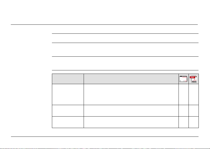
Name Description/Format
3D Disto User
Manual
3D Disto Quick
Start
Safety Manual Provides important safety instructions for use of
All instructions required in order to operate the
instrument to a basic level are contained in this User
Manual. Provides an overview of the instrument
together with technical data and safety directions.
Intended as a quick reference field guide.
3D Disto.
-
9

3D Disto, How to Use this Manual
Refer to the following resources for all 3D Disto documentation/software:
• the Leica 3D Disto CD
• https://myworld.leica-geosystems.com
myWorld@Leica Geosystems (https://myworld.leica-geosystems.com) offers a wide
range of services, information and training material.
With direct access to myWorld, you are able to access all relevant services whenever
it is convenient for you, 24 hours a day, 7 days per week. This increases your efficiency and keeps you and your equipment instantly updated with the latest information from Leica Geosystems.
10

3D Disto, How to Use this Manual
11

3D Disto, How to Use this Manual
Service Description
myProducts Simply add all Leica Geosystems products that you and your
mySupport Create new support requests for your products that will be
myTraining Enhance your product knowledge with the Leica Geosystems
12
company own. View detailed information on your products, buy
additional options, update your products with the latest software
and keep up-to-date with the latest documentation.
answered by your local Leica Geosystems Support Team. View the
complete history of your Support and view detailed information on
each request in case you want to refer to previous support
requests.
Campus - Information, Knowledge, Training. Study the latest online
training material or download training material on your products.
Keep up-to-date with the latest News on your products and
register for Seminars or Courses in your country.
2 Technical Terms and Abbreviations
3D Disto_013
a
b
c
a
3D Disto_015
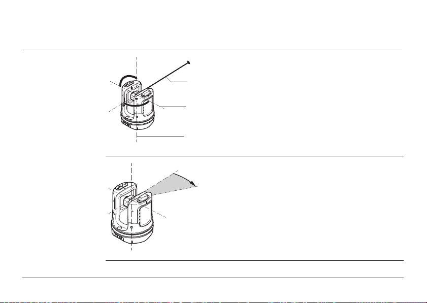
Line of sight
Horizontal angle
3D Disto, Technical Terms and Abbreviations
a) Line of sight
b) Tilting axis, horizontal rotation axis of the
instrument
c) Standing axis, vertical rotation axis of the
instrument
a) Horizontal angle, in [°] or [gon]
Line of sight, laser beam and crosshair
must be congruent. Refer to "9 Check &
Adjust" for more information.
13

3D Disto, Technical Terms and Abbreviations
3D Disto_016
a
3D Disto_017
a
Vertical angle
14
Setting: Horizon = 0
a) Vertical angle, in [°], [gon], [1:n] or [%]
Setting: Horizon = 90° / 100gon
a) Vertical angle, in [°] or [gon]

Distances
a
3D Disto_018
3D Disto_019
a) Orthogonal distance
a
b
c
a) Tie distance
b) Vertical distance = height difference
c) Horizontal distance
3D Disto, Technical Terms and Abbreviations
15

3D Disto, Technical Terms and Abbreviations
3D Disto_014
a
b
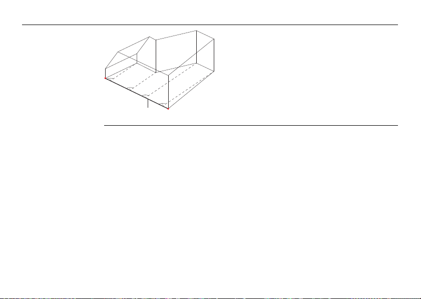
Areas
a
b
3D Disto_020
Zenith and horizon
16
a) Tilted area, as measured
b) Horizontal area, calculated by 3D Disto
a) Zenith:
Point on the plumb line above/below the
observer.
b) Horizon:
Plane/Line 90° to the plumb line.

References
+3.00
+2.10
0.00
-0.02
0.00
3D Disto_021
1.884
5.390
3D Disto_022
4.160
3.965
a
3D Disto, Technical Terms and Abbreviations
a
0.00
a) Reference height:
A level that all heights refer to.
5.134
a) Reference point:
A point that all dimensions refer to.
17
3D Disto, Technical Terms and Abbreviations
3D Disto_023
3.101
2.911
7.040
7.002
a
18
a) Reference line:
A line that all dimensions refer to.
Tilt sensor The tilt sensor guarantees correct results even if you do not set up the 3D Disto
3D Disto_024
3D Disto_025
0-3°
exactely horizontal.
Tilt sensor off = disabled
All measurement results relate to the
tilted axis and horizon of the 3D Disto.
3D Disto, Technical Terms and Abbreviations
Tilt sensor on = enabled
Measurement results are correctly horizontal if the 3D Disto is set up between
0° and 3°.
19

3D Disto, Technical Terms and Abbreviations
S_3D Disto_002 a b
Viewfinder and
Crosshair
• The so called Viewfinder is an integrated camera which shows the target on the
Control Unit display.
•The crosshair is an aiming guide displayed on the Control Unit.
20
a) Viewfinder
b) Crosshair

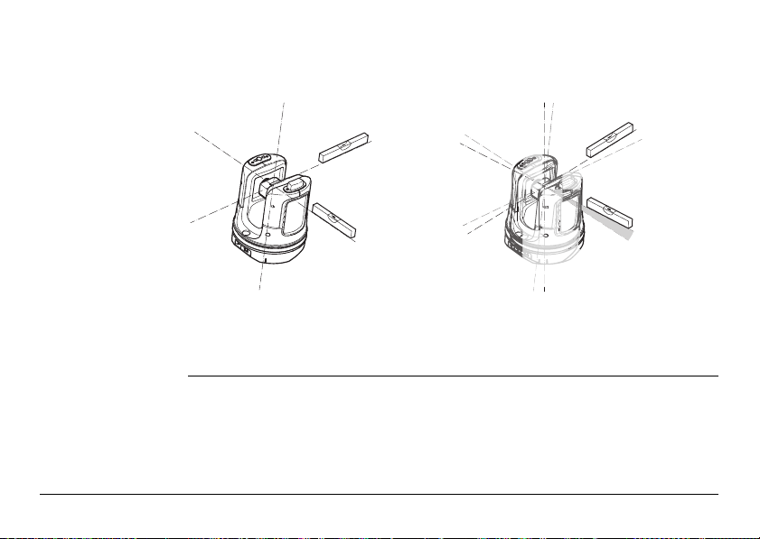
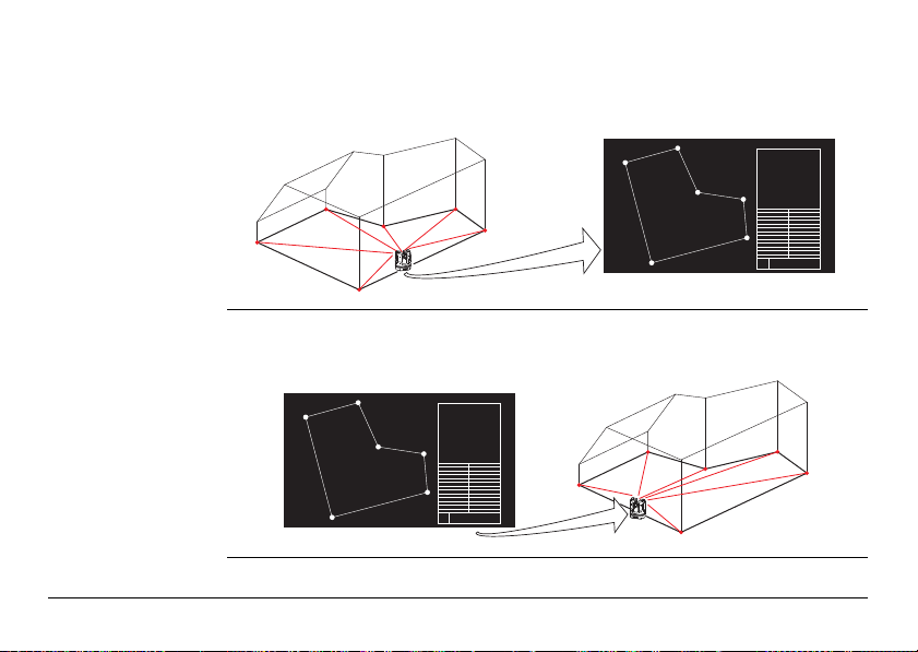
Secure Points Secure Points lock a measurement to a coordinate system. These reference
3D Disto_026
points allow to change the 3D Disto’s location or to continue a measurement at a
later time, so that all measurements fit together perfectly.
1. Name and place three to five self-adhesive
target marks on walls, ceiling or floor around
your working area.
2. Measure these target marks and save them as
Secure Points.
3. Relocate the 3D Disto or set it up "anywhere"
at a later time.
4. Measure the Secure Points again. 3D Disto
relocates itself and measurement works can
be continued.
3D Disto_027
Refer to "7.3 Location" for more information.
3D Disto, Technical Terms and Abbreviations
21

3D Disto, Technical Terms and Abbreviations
3D Disto_028
b
a
m/ft
Coordinates Coordinates describe the position of a point in the two or three dimensional room.
a) Two dimensional coordinates
b) Three dimensional coordinates
22
Measure Measurement results can be transferred to a connected PC or USB stick for post-
3D Disto_045
CAD
3D Disto_046
CAD
processing.
Layout or
projection
Design data in DXF format can be imported and used to lay out the according points
or grids.
3D Disto, Technical Terms and Abbreviations
23

3D Disto, Technical Terms and Abbreviations
Laser distance
meter (LDM)
The laser distance meter (LDM) allows to determine the distance by using a visible
red laser beam.
24
Calibration Calibration is a workflow to check and adjust the accuracy of the instrument.
Refer to "9 Check & Adjust" for more information.
Ruler for offset
points
Ruler for offset points is an accessory that allows to measure inaccessible or hidden
points.
?
3D Disto_035
a) Ruler for offset points
a
3 Description of the System
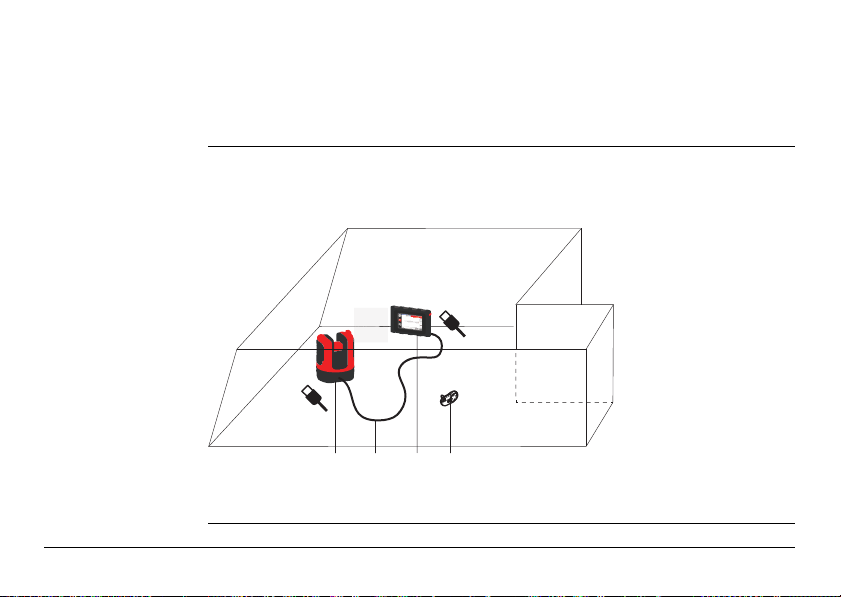
3D Disto_001 a b c d
3.1 General 3D Disto System Information
General
information
Leica Geosystems’ 3D Disto is a three dimensional measuring and projection system
that allows to measure points in a room from one setup position and generates 3D
data – ready to use or for post-processing.
3D Disto is operated via the Control Unit. Certain functions can also be managed by
the RM100 Remote Control.
3D Disto, Description of the System
a) Control Unit
b) USB cable
c) 3D Disto
d) RM100 Remote
Control
25

3D Disto, Description of the System
ab
e
f g hd
c
3D Disto_002
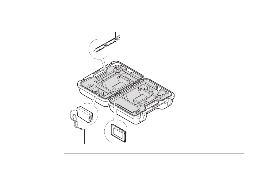
3.2 Container Contents
Container
contents,
part 1 of 2
26
a) 3D Disto with inbuilt SD WLAN Card
b) USB Connection Cable 3D Disto to
the Control Unit
Power Cable 3D Disto to the Control
Unit
Mini-USB Cable for PC
c) Data CD
Safety Instructions Manual,
3D Disto Getting Started Guide,
CE & Producer Certificate,
USB Stick
d) Four country-specific cables for
Power Supply 3D Disto
e) Target Marks, self-adhesive, 50 units
in one bag
f) RM100 Remote Control
g) Control Unit power supply
h) Country-specific adapter plug-ins for
Control Unit power supply
Container
i
j
3D Disto_003
k
contents,
part 2 of 2
i) Ruler for offset points
j) Power Supply 3D Disto
k) Control Unit with Pen,
Tripod Clamp and Hand
strap
3D Disto, Description of the System
27

3D Disto, Description of the System
3.3 Instrument Components
3.3.1 3D Disto
28
Instrument
components,
motor-driven part
a
b
c
3D Disto_004
c
d
e
c
f
a) LEDs for 3D Disto status
b) ON/OFF button
c) Trays to hold the instrument
g
d) Infrared (IR) interface
e) WLAN interface
f) Laser distance meter with Viewfinder
g) Circular bubble

Instrument
3D Disto_005
dc e f bba
component,
battery socket
a) Tripod thread 5/8”
b) 90° marking
c) Power supply connector for 3D Disto
d) LED for battery status
e) Data cable connector
f) Power supply connector to Control
Unit
Description of buttons and LEDs
Button/LEDs Description
ON/OFF button Button to turn instrument ON or OFF.
Instrument turns OFF after 15 minutes if not connected to the
Control Unit.
3D Disto, Description of the System
29

3D Disto, Description of the System
Button/LEDs Description
LEDs for 3D Disto
status
LED for battery
status
30
• Green and orange LEDs flash: If 3D Disto is turned ON.
• Orange LED flashes fast: Booting and Self-Levelling Procedure is running.
• Green LED flashes slowly: tilt 3° after Self-Levelling check.
3D Disto is ready for measurement. Tilt sensor is on.
• Orange LED flashes fast: tilt >3° after Self-Levelling check.
• Green LED off, orange LED flashes continuously:
An error happened. Refer to "8 Error Messages" for more
information.
For experts only: Tilt sensor off
• Green LED flashes slowly, followed by orange LED flashing
three times while green LED is off.
If instrument is on and connected to the charger:
• Green LED 1x flashing: Battery is charged to 25 %.
• Green LED 2x flashing: Battery is charged to 50 %.
• Green LED 3x flashing: Battery is charged to 75 %.
• Green LED flashes: Battery is fully charged.
 Loading...