

Page 1

Leica TS13
User Manual
V
ersion 1.0
English
Page 2
Introduction
Congratulations on the purchase of the Leica TS13.
This manual contains important safety directions as well as instructions for setting up the p
roduct and operating it. Refer to "1 Safety Directions" for further
information.
Read carefully through the User Manual before you switch on the product.
The model and serial number of your product are indicated on the type plate.
A
lways refer to this information when you need to contact your agency or
Leica Geosystems authorised service centre.
•
Windows is a r
egistered trademark of Microsoft Corporation in the United
States and other countries
•
Bluetooth
®
is a registered trademark of Bluetooth SIG, Inc.
•
SD Logo is a trademark of SD-3C, LLC.
All other trademarks are the property of their respective owners.
This manual applies to the TS13.
Name Description/Format
TS13 Quick Guide Provides an overview of the product
t
ogether with technical data and
safety directions. Intended as a quick
reference guide.
ü ü
TS13 User Manual All instructions required in order to
operate the product to a basic level
are contained in the User Manual.
Provides an overview of the product
together with technical data and
safety directions.
-
ü
Name Description/Format
Captivate Technical
R
eference Manual
Overall comprehensive guide to the
product and apps. Included are
detailed descriptions of special software/hardware settings and software/hardware functions intended
for technical specialists.
-
ü
Refer to the following resources for documentation/software:
•
the Leica Cap
tivate USB documentation card
•
https://myworld.leica-geosystems.com
Video tutorials are available on:
h
ttp://www.leica-geosystems.com/captivate-howto
Purchase
Product identification
Trademarks
Validity of this manual
Available
do
cumentation
2
Page 3

On the last page of this manual, you can find the address of Leica Geosystems
he
adquarters. For a list of regional contacts, please visit
http://leica-geosystems.com/contact-us/sales_support.
myWorld@Leica Geosystems (h
ttps://myworld.leica-geosystems.com) offers
a wide range of services, information and training material.
With direct access to myWorld, you are able to access all relevant services
whenever it is convenient for you.
Service Description
myProducts Add all products that you and your company own
and explo
re your world of Leica Geosystems: View
detailed information on your products and update
your products with the latest software and keep upto-date with the latest documentation.
myService View the current service status and full service his-
tory of your products in Leica Geosystems service
centres. Access detailed information on the services
performed and download your latest calibration certificates and service reports.
mySupport Create new support requests for your products that
will be answered by your local Leica Geosystems
Support Team. View the complete history of your
support requests and view detailed information on
each request in case you want to refer to previous
support requests.
myTraining Enhance your product knowledge with Leica Geosys-
tems Campus - Information, Knowledge, Training.
Study the latest online training material on your
products and register for seminars or courses in your
country.
myTrustedServices Add your subscriptions and manage users for Leica
Geosystems Trusted Services, the secure software
services, that assist you to optimise your workflow
and increase your efficiency.
Leica Geosystems
a
ddress book
3
Page 4

Table of Contents
1 Safety Directions 6
1.1 General Introduction 6
1.2 Definition of Use 7
1.3 Limits of Use 7
1.4 Responsibilities 7
1.5 Hazards of Use 8
1.6 Laser Classification 11
1.6.1 General 11
1.6.2 Distancer, Measurements with Reflectors 12
1.6.3 Distancer, Measurements without Reflectors 12
1.6.4 Red Laser Pointer 14
1.6.5 Automatic Target Aiming ATR 16
1.6.6 SpeedSearch 17
1.6.7 Electronic Guide Light EGL 17
1.6.8 Laser Plummet 18
1.7 Electromagnetic Compatibility EMC 19
1.8 FCC Statement, Applicable in U.S. 20
1.9 ICES-003 Statement, Applicable in Canada 23
2 Description of the System 24
2.1 System Components 24
2.2 System Concept 26
2.2.1 Software Concept 26
2.2.2 Power Concept 28
2.2.3 Data Storage Concept 28
2.3 Container Contents 29
2.4 Instrument Components 31
3 User Interface 33
3.1 Keyboard 33
3.1.1 Four Button Keyboard Unit 33
3.1.2 Keyboard Display Unit 34
3.2 Operating Principles 35
4 Operation 37
4.1 Setting Up the TS Instrument 37
4.2 Setting up for Remote Control (with the RadioHandle) 37
4.3 Fixing the Field Controller to a Holder and Pole 39
4.4 Connecting to a Personal Computer 40
4.5 Power Functions 43
4.6 Batteries 43
4.6.1 Operating Principles 43
4.6.2 Battery for the TS Instrument 44
4.7 Working with the Memory Device 44
4.8 LED Indicators 46
4.9 Guidelines for Correct Results 47
5 Check & Adjust 49
5.1 Overview 49
5.2 Preparation 50
5.3 Combined Adjustment
(l, t, i, c and A
TR)
51
5.4 Tilting Axis Adjustment (a) 53
5.5 Adjusting the Circular Level of the Instrument and Tribrach 55
5.6 Adjusting the Circular Level of the Prism Pole 56
4 Table of Contents
Page 5

5.7 Inspecting the Laser Plummet of the Instrument 56
5.8 Servicing the Tripod 57
6 Care and Transport 58
6.1 Transport 58
6.2 Storage 58
6.3 Cleaning and Drying 59
6.4 Maintenance 59
7 Technical Data 60
7.1 Angle Measurement 60
7.2 Distance Measurement with Reflectors 60
7.3 Distance Measurement without Reflectors
(N
on-Prism mode)
61
7.4 Distance Measurement - Long Range (LO mode) 62
7.5 Automatic Target Aiming (ATR) 63
7.6 Lock 64
7.7 SpeedSearch 64
7.8 Leica LOC8 Theft Deterrence – Positioning, Tracking and Locking 65
7.9 SmartStation 65
7.9.1 SmartStation Accuracy 65
7.9.2 SmartStation Dimensions 66
7.10 Conformity to National Regulations 66
7.10.1 TS13 66
7.10.2 RadioHandle 67
7.10.3 Dangerous Goods Regulations 68
7.11 General Technical Data of the Product 68
7.12 Scale Correction 74
7.13 Reduction Formulas 77
8 Software Licence Agreement 80
Table of Contents 5
Page 6
1 Safety Directions
1.1 General Introduction
The following directions enable the person responsible for the product, and the
p
erson who actually uses the equipment, to anticipate and avoid operational
hazards.
The person responsible for the product must ensure that all users understand
these directions and adhere to them.
Warning messages are an essential part of the safety concept of the instrumen
t. They appear wherever hazards or hazardous situations can occur.
Warning messages...
•
mak
e the user alert about direct and indirect hazards concerning the use
of the product.
•
contain general rules of behaviour.
For the users‘ safety, all safety instructions and safety messages shall be
s
trictly observed and followed! Therefore, the manual must always be available
to all persons performing any tasks described here.
DANGER, WARNING, CAUTION and NOTICE are standardised signal words for
identifying levels of hazards and risks related to personal injury and property
damage. For your safety, it is important to read and fully understand the following table with the different signal words and their definitions! Supplementary safety information symbols may be placed within a warning message as
well as supplementary text.
Type Description
DANGER
Indicates an imminently hazardous situation
which, if no
t avoided, will result in death or
serious injury.
WARNING
Indicates a potentially hazardous situation or
an unin
tended use which, if not avoided,
could result in death or serious injury.
CAUTION
Indicates a potentially hazardous situation or
an unin
tended use which, if not avoided,
may result in minor or moderate injury.
NOTICE
Indicates a potentially hazardous situation or
an unintended use which, if not avoided,
may result in appreciable material, financial
and environmental damage.
☞
Important paragraphs which must be adhered
to in practice as they enable the product to
be used in a technically correct and efficient
manner.
Description
About warning
m
essages
6 Safety Directions
Page 7
1.2 Definition of Use
•
Me
asuring horizontal and vertical angles.
•
Measuring distances.
•
Recording measurements.
•
Automatic target search, recognition and tracking.
•
Visualising the aiming direction and vertical axis.
•
Remote control of product.
•
Data communication with external appliances.
•
Measuring raw data and computing coordinates using carrier phase and
code signal from GNSS satellites.
•
Recording GNSS and point related data.
•
Computing with software.
•
Us
e of the product without instruction.
•
Use outside of the intended use and limits.
•
Disabling safety systems.
•
Removal of hazard notices.
•
Opening the product using tools, for example screwdriver, unless this is
permitted for certain functions.
•
Modification or conversion of the product.
•
Use after misappropriation.
•
Use of products with recognisable damages or defects.
•
Use with accessories from other manufacturers without the prior explicit
approval of Leica Geosystems.
•
Deliberate dazzling of third parties.
•
Controlling of machines, moving objects or similar monitoring application
without additional control and safety installations.
•
Aiming directly into the sun.
•
Inadequate safeguards at the working site.
1.3 Limits of Use
Suitable for use in an atmosphere appropriate for permanent human habitatio
n: not suitable for use in aggressive or explosive environments.
WARNING
Working in hazardous areas, or close to electrical installations or similar sit
uations.
Life Risk.
Precautions:
▶
Local safety authorities and safety experts must be contacted by the person responsible for the product before working in such conditions.
1.4 Responsibilities
Leica Geosystems AG, CH-9435 Heerbrugg, hereinafter referred to as Leica
G
eosystems, is responsible for supplying the product, including the User Man-
ual and original accessories, in a safe condition.
Intended use
Reasonably
f
orseeable misuse
Environment
Manufacturer of the
pr
oduct
Safety Directions 7
Page 8
The person responsible for the product has the following duties:
•
T
o understand the safety instructions on the product and the instructions
in the User Manual.
•
To ensure that it is used in accordance with the instructions.
•
To be familiar with local regulations relating to safety and accident prevention.
•
To inform Leica Geosystems immediately if the product and the application
becomes unsafe.
•
To ensure that the national laws, regulations and conditions for the operation of the product are respected.
1.5 Hazards of Use
NOTICE
Dropping, misusing, modifying, storing the product for long periods or
transporting the product
Watch out for erroneous measurement results.
Precautions:
▶
Periodically carry out test measurements and perform the field adjustments indicated in the User Manual, particularly after the product has been
subjected to abnormal use as well as before and after important measurements.
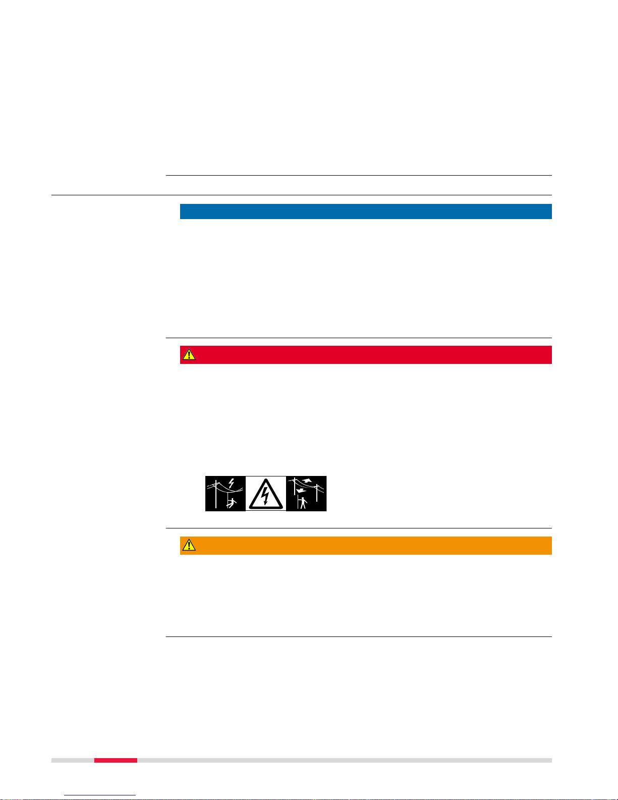
DANGER
Risk of electrocution
Becaus
e of the risk of electrocution, it is dangerous to use poles, levelling
staffs and extensions in the vicinity of electrical installations such as power
cables or electrical railways.
Precautions:
▶
Keep at a safe distance from electrical installations. If it is essential to
work in this environment, first contact the safety authorities responsible
for the electrical installations and follow their instructions.
WARNING
Lightning strike
If the p
roduct is used with accessories, for example masts, staffs, poles, you
may increase the risk of being struck by lightning.
Precautions:
▶
Do not use the product in a thunderstorm.
Person responsible
f
or the product
8 Safety Directions
Page 9
WARNING
Distraction/loss of attention
Dur
ing dynamic applications, for example stakeout procedures, there is a danger of accidents occurring if the user does not pay attention to the environmental conditions around, for example obstacles, excavations or traffic.
Precautions:
▶
The person responsible for the product must make all users fully aware of
the existing dangers.
WARNING
Inadequate securing of the working site.
T
his can lead to dangerous situations, for example in traffic, on building sites
and at industrial installations.
Precautions:
▶
Always ensure that the working site is adequately secured.
▶
Adhere to the regulations governing safety, accident prevention and road
traffic.
CAUTION
Pointing product toward the sun
Be car
eful when pointing the product toward the sun, because the telescope
functions as a magnifying glass and can injure your eyes and/or cause damage
inside the product.
Precautions:
▶
Do not point the product directly at the sun.
CAUTION
Not properly secured accessories.
If the ac
cessories used with the product are not properly secured and the
product is subjected to mechanical shock, for example blows or falling, the
product may be damaged or people can sustain injury.
Precautions:
▶
When setting up the product, make sure that the accessories are correctly
adapted, fitted, secured, and locked in position.
▶
Avoid subjecting the product to mechanical stress.
Safety Directions 9
Page 10
WARNING
Inappropriate mechanical influences to batteries
Dur
ing the transport, shipping or disposal of batteries it is possible for inappro-
priate mechanical influences to constitute a fire hazard.
Precautions:
▶
Before shipping the product or disposing it, discharge the batteries by the
product until they are flat.
▶
When transporting or shipping batteries, the person in charge of the product must ensure that the applicable national and international rules and
regulations are observed.
▶
Before transportation or shipping, contact your local passenger or freight
transport company.
WARNING
Exposure of batteries to high mechanical stress, high ambient temperat
ures or immersion into fluids
This can cause leakage, fire or explosion of the batteries.
Precautions:
▶
Protect the batteries from mechanical influences and high ambient temperatures. Do not drop or immerse batteries into fluids.
WARNING
Short circuit of battery terminals
If ba
ttery terminals are short circuited e.g. by coming in contact with jewellery,
keys, metallised paper or other metals, the battery can overheat and cause
injury or fire, for example by storing or transporting in pockets.
Precautions:
▶
Make sure that the battery terminals do not come into contact with metallic objects.
WARNING
Moving parts at the product during operation
Risk o
f squeezing extremities or entanglement of hair and/or clothes.
Precautions:
▶
Keep a safe distance to the moving parts.
10 Safety Directions
Page 11
WARNING
Improper disposal
If the p
roduct is improperly disposed of, the following can happen:
•
If polymer parts are burnt, poisonous gases are produced which may
impair health.
•
If batteries are damaged or are heated strongly, they can explode and
cause poisoning, burning, corrosion or environmental contamination.
•
By disposing of the product irresponsibly you may enable unauthorised
persons to use it in contravention of the regulations, exposing themselves
and third parties to the risk of severe injury and rendering the environment
liable to contamination.
•
Improper disposal of silicone oil may cause environmental contamination.
•
The product does include parts of Beryllium inside. Any modification of
some internal parts can release Beryllium dust or fragments, creating a
health hazard.
Precautions:
▶
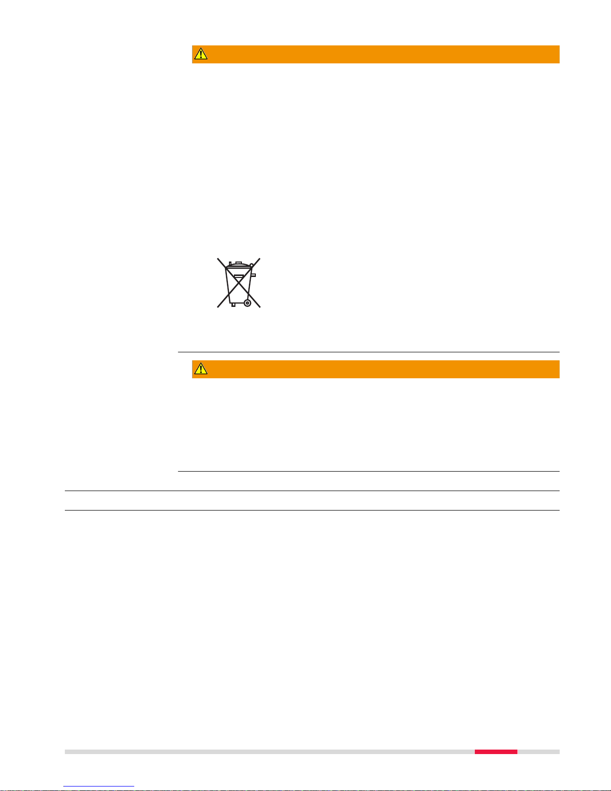
The product must not be disposed with household waste.
Dispose of the product appropriately in accordance with
the national regulations in force in your country.
Always prevent access to the product by unauthorised
personnel.
Product-specific treatment and waste management information can be
received from your Leica Geosystems distributor.
WARNING
Improperly repaired equipment
Risk o
f injuries to users and equipment destruction due to lack of repair knowl-
edge.
Precautions:
▶
Only Leica Geosystems authorised service centres are entitled to repair
these products.
1.6 Laser Classification
1.6.1 General
The following chapters provide instructions and training information about laser
sa
fety according to international standard IEC 60825-1 (2014-05) and technical
report IEC TR 60825-14 (2004-02). The information enables the person
responsible for the product and the person who actually uses the equipment,
to anticipate and avoid operational hazards.
☞
According to IEC TR 60825-14 (2004-02), products classified as laser
class 1, class 2 and class 3R do no
t require:
•
laser safety officer involvement,
•
protective clothes and eyewear,
•
special warning signs in the laser working area
if used and operated as defined in this User Manual due to the low
eye hazard level.
General
Safety Directions 11
Page 12
☞
National laws and local regulations could impose more stringent
ins
tructions for the safe use of lasers than IEC 60825-1 (2014-05)
and IEC TR 60825-14 (2004-02).
1.6.2 Distancer, Measurements with Reflectors
The EDM module built into the product produces a visible laser beam which
emer
ges from the telescope objective.
The laser product described in this section is classified as laser class 1 in
ac
cordance with:
•
IE
C 60825-1 (2014-05): “Safety of laser products”
These products are safe under reasonably foreseeable conditions of operation
and ar
e not harmful to the eyes provided that the products are used and main-
tained in accordance with this User Manual.
Description Value
Wavelength 658 nm
Pulse duration 800 ps
Pulse repetition frequency (PRF) 100 MHz
Maximum average radiant power 0.33 mW
Beam divergance 1.5 mrad x 3 mrad
0016217_001
a
a Laser beam
1.6.3 Distancer, Measurements without Reflectors
The EDM module built into the product produces a visible laser beam which
emerges from the telescope objective.
The laser product described in this section is classified as laser class 3R in
ac
cordance with:
•
IE
C 60825-1 (2014-05): “Safety of laser products”
Direct intrabeam viewing may be hazardous (low eye hazard level), in particular
f
or deliberate ocular exposure. The beam may cause dazzle, flash-blindness
and after-images, particularly under low ambient light conditions. The risk of
injury for laser class 3R products is limited because of:
General
General
12 Safety Directions
Page 13
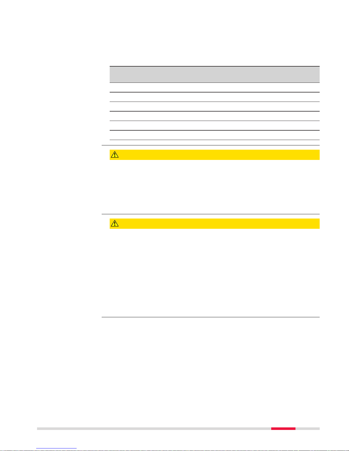
a) unin
tentional exposure would rarely reflect worst case conditions of (e.g.)
beam alignment with the pupil, worst case accommodation,
b) inherent safety margin in the maximum permissible exposure to laser radi-
ation (MPE)
c) natural aversion behaviour for exposure to bright light for the case of visi-
ble radiation.
Description Value
(R500/R1000)
Wavelength 658 nm
Maximum average radiant power 4.8 mW
Pulse duration 800 ps
Pulse repetition frequency (PRF) 100 MHz
Beam divergence 0.2 mrad x 0.3 mrad
NOHD (Nominal Ocular Hazard Distance) @ 0.25 s 44 m / 144 ft
CAUTION
Class 3R laser products
F
rom a safety perspective, class 3R laser products should be treated as poten-
tially hazardous.
Precautions:
▶
Prevent direct eye exposure to the beam.
▶
Do not direct the beam at other people.
CAUTION
Reflected beams aimed at reflecting surfaces
P
otential hazards are not only related to direct beams but also to reflected
beams aimed at reflecting surfaces such as prisms, windows, mirrors, metallic
surfaces, etc.
Precautions:
▶
Do not aim at areas that are essentially reflective, such as a mirror, or
which could emit unwanted reflections.
▶
Do not look through or beside the optical sight at prisms or reflecting
objects when the laser is switched on, in laser pointer or distance measurement mode. Aiming at prisms is only permitted when looking through
the telescope.
Safety Directions 13
Page 14
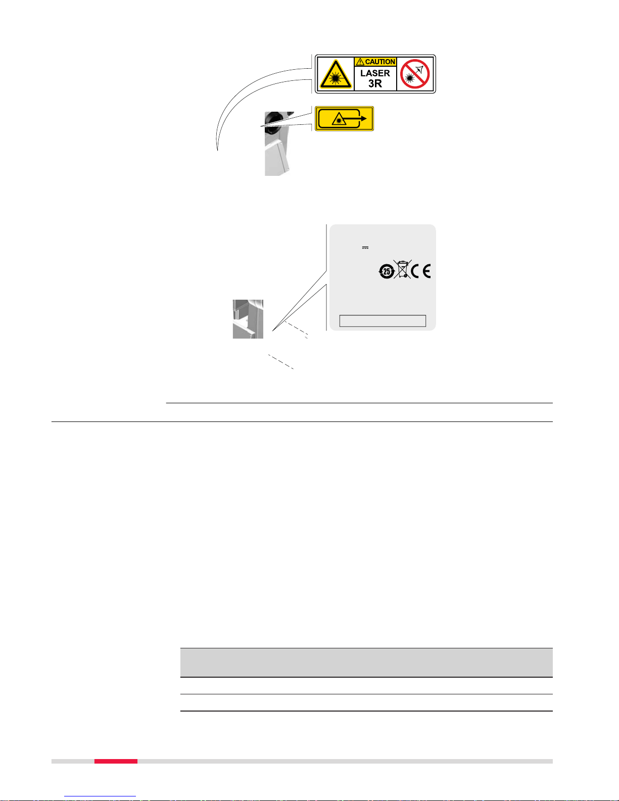
0016218_001
Pav = 4.8mW λ = 658nm t p = 800ps
IEC 60825-1:2014
Complies wit h FDA performa nce standards f or laser produc ts except for
deviations pur suant to Laser No tice No. 50, dat ed June 24, 2007.
This device complies with part 15 of the FCC Rules.
Operation is s ubject to the foll owing two cond itions:
(1) This device may not cause harmful interference, and
(2) This devi ce must accept any i nterferenc e received, inc luding inter ference
that may cause unde sired operat ion.
123456
S.No.:
123456
Art.No.:
Equip.No.: 1234567
Power: 12-15V 12W ma x
Leica Geosystems AG
CH-9435 Heerbrugg
Manufactured: 20XX
Made in Swit zerland
TS13
Model:
0016219_001
1.6.4 Red Laser Pointer
The laser pointer built into the product produces a visible red laser beam which
emer
ges from the telescope objective.
The laser product described in this section is classified as laser class 3R in
ac
cordance with:
•
IE
C 60825-1 (2014-05): “Safety of laser products”
Direct intrabeam viewing may be hazardous (low eye hazard level), in particular
f
or deliberate ocular exposure. The beam may cause dazzle, flash-blindness
and after-images, particularly under low ambient light conditions. The risk of
injury for laser class 3R products is limited because of:
a) unin
tentional exposure would rarely reflect worst case conditions of (e.g.)
beam alignment with the pupil, worst case accommodation,
b) inherent safety margin in the maximum permissible exposure to laser radi-
ation (MPE)
c) natural aversion behaviour for exposure to bright light for the case of visi-
ble radiation.
Description Value
(R500/R1000)
Wavelength 658 nm
Maximum average radiant power 4.8 mW
Labelling
General
14 Safety Directions
Page 15
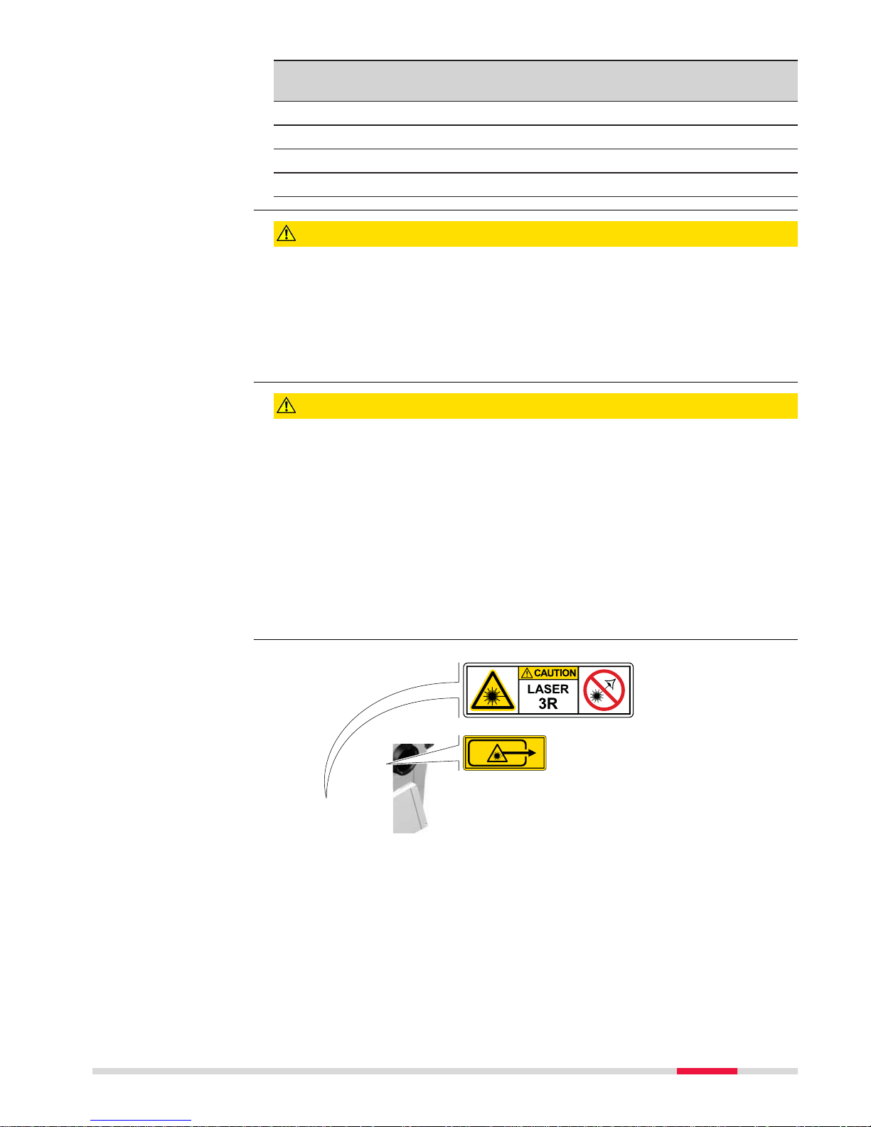
Description Value
(R500/R1000)
Pulse duration 800 ps
Pulse repetition frequency (PRF) 100 MHz
Beam divergence 0.2 mrad x 0.3 mrad
NOHD (Nominal Ocular Hazard Distance) @ 0.25 s 44 m / 144 ft
CAUTION
Class 3R laser products
F
rom a safety perspective, class 3R laser products should be treated as poten-
tially hazardous.
Precautions:
▶
Prevent direct eye exposure to the beam.
▶
Do not direct the beam at other people.
CAUTION
Reflected beams aimed at reflecting surfaces
P
otential hazards are not only related to direct beams but also to reflected
beams aimed at reflecting surfaces such as prisms, windows, mirrors, metallic
surfaces, etc.
Precautions:
▶
Do not aim at areas that are essentially reflective, such as a mirror, or
which could emit unwanted reflections.
▶
Do not look through or beside the optical sight at prisms or reflecting
objects when the laser is switched on, in laser pointer or distance measurement mode. Aiming at prisms is only permitted when looking through
the telescope.
0016218_001
Labelling
Safety Directions 15
Page 16
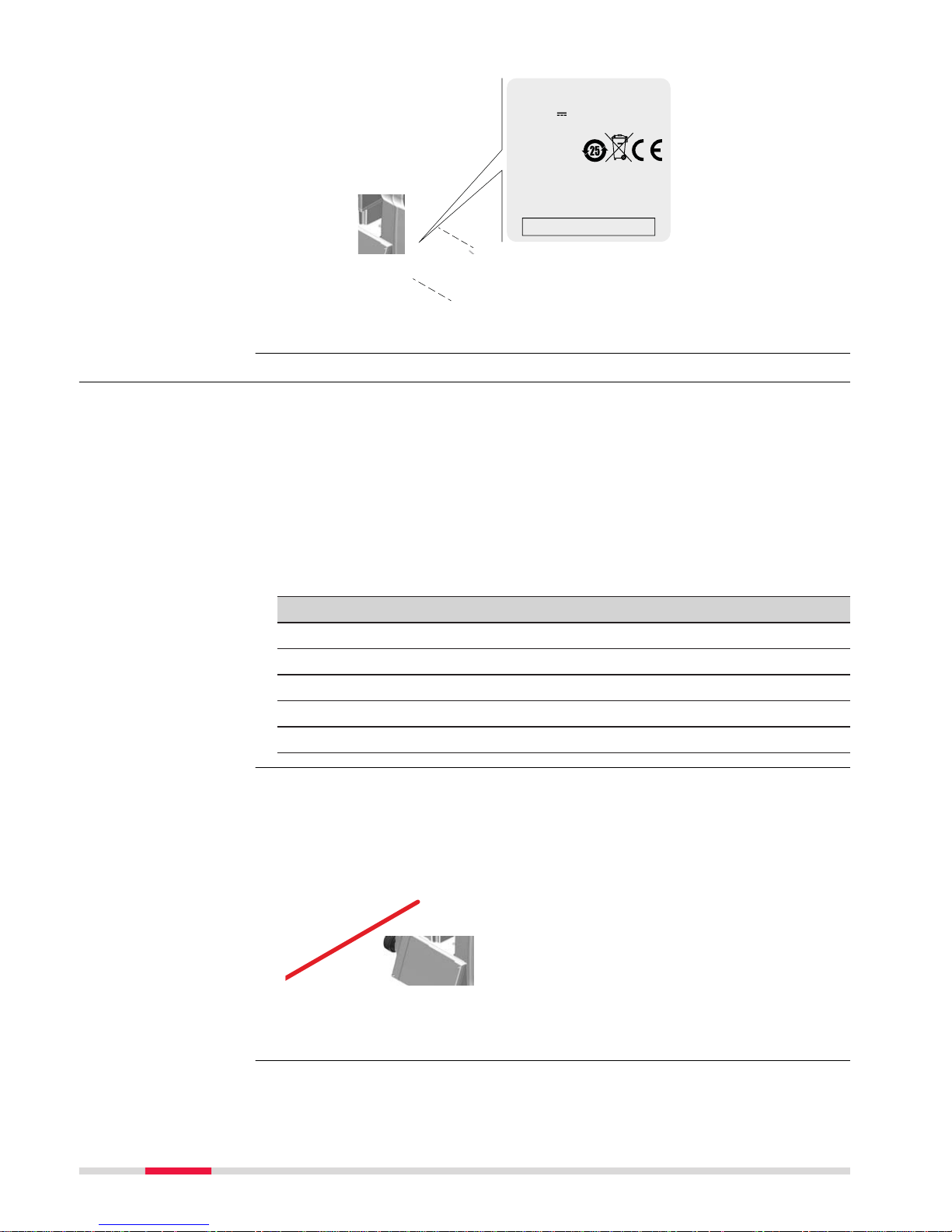
Pav = 4.8mW λ = 658nm t p = 800ps
IEC 60825-1:2014
Complies wit h FDA performa nce standards f or laser produc ts except for
deviations pur suant to Laser No tice No. 50, dat ed June 24, 2007.
This device complies with part 15 of the FCC Rules.
Operation is s ubject to the foll owing two cond itions:
(1) This device may not cause harmful interference, and
(2) This devi ce must accept any i nterferenc e received, inc luding inter ference
that may cause unde sired operat ion.
123456
S.No.:
123456
Art.No.:
Equip.No.: 1234567
Power: 12-15V 12W ma x
Leica Geosystems AG
CH-9435 Heerbrugg
Manufactured: 20XX
Made in Swit zerland
TS13
Model:
0016219_001
1.6.5 Automatic Target Aiming ATR
The Automatic Target Aiming built into the product produces an invisible laser
b
eam which emerges from the telescope objective.
The laser product described in this section is classified as laser class 1 in
accordance with:
•
IE
C 60825-1 (2014-05): “Safety of laser products”
These products are safe under reasonably foreseeable conditions of operation
and ar
e not harmful to the eyes provided that the products are used and main-
tained in accordance with this User Manual.
Description Value
Wavelength 785 nm
Maximum radiant peak power per pulse 10 mW
Pulse duration £ 15 ms
Pulse repetition frequency (PRF) £ 213 Hz
Beam divergence 25 mrad
0016217_001
a
a Laser beam
General
16 Safety Directions
Page 17

1.6.6 SpeedSearch
For this functionality, the TS13 Robotic licence must be purchased.
The SpeedSearch built into the product produces an invisible laser beam which
emer
ges from the front side of the telescope.
The laser product described in this section is classified as laser class 1 in
ac
cordance with:
•
IE
C 60825-1 (2014-05): “Safety of laser products”
These products are safe under reasonably foreseeable conditions of operation
and are not harmful to the eyes provided that the products are used and maintained in accordance with this User Manual.
Description Value
Wavelength 850 nm
Maximum average radiant power 11 mW
Pulse duration 20 ns, 40 ns
Pulse repetition frequency (PRF) 24.4 kHz
Beam divergance 0.4 mrad x 700 mrad
0016220_001
a
a Laser beam
1.6.7 Electronic Guide Light EGL
The Electronic Guide Light built into the product produces a visible LED beam
which emerges from the front side of the telescope.
☞
The product described in this section, is excluded from the scope of
IEC 60825-1 (2014-05): “Safety of laser products”.
The product described in this section, is classified as exempt group in
accordance with IEC 62471 (2006-07) and does not pose any hazard
provided that the product is used and maintained in accordance with
this user manual.
Availability
General
General
Safety Directions 17
Page 18

0016221_001
a
b
a LED beam red
b
LED beam yellow
1.6.8 Laser Plummet
The laser plummet built into the product produces a visible red laser beam
which emer
ges from the bottom of the product.
The laser product described in this section is classified as laser class 2 in
accordance with:
•
IE
C 60825-1 (2014-05): “Safety of laser products”
These products are safe for momentary exposures but can be hazardous for
delib
erate staring into the beam. The beam may cause dazzle, flash-blindness
and after-images, particularly under low ambient light conditions.
Description Value
Wavelength 640 nm
Maximum average radiant power 0.95 mW
Pulse duration 0.1 ms - cw
Pulse repetition frequency (PRF) 1 kHz
Beam divergance <1.5 mrad
CAUTION
Class 2 laser product
From a safety perspective, class 2 laser products are not inherently safe for the
eyes.
Precautions:
▶
Avoid staring into the beam or viewing it through optical instruments.
▶
Avoid pointing the beam at other people or at animals.
General
18 Safety Directions
Page 19
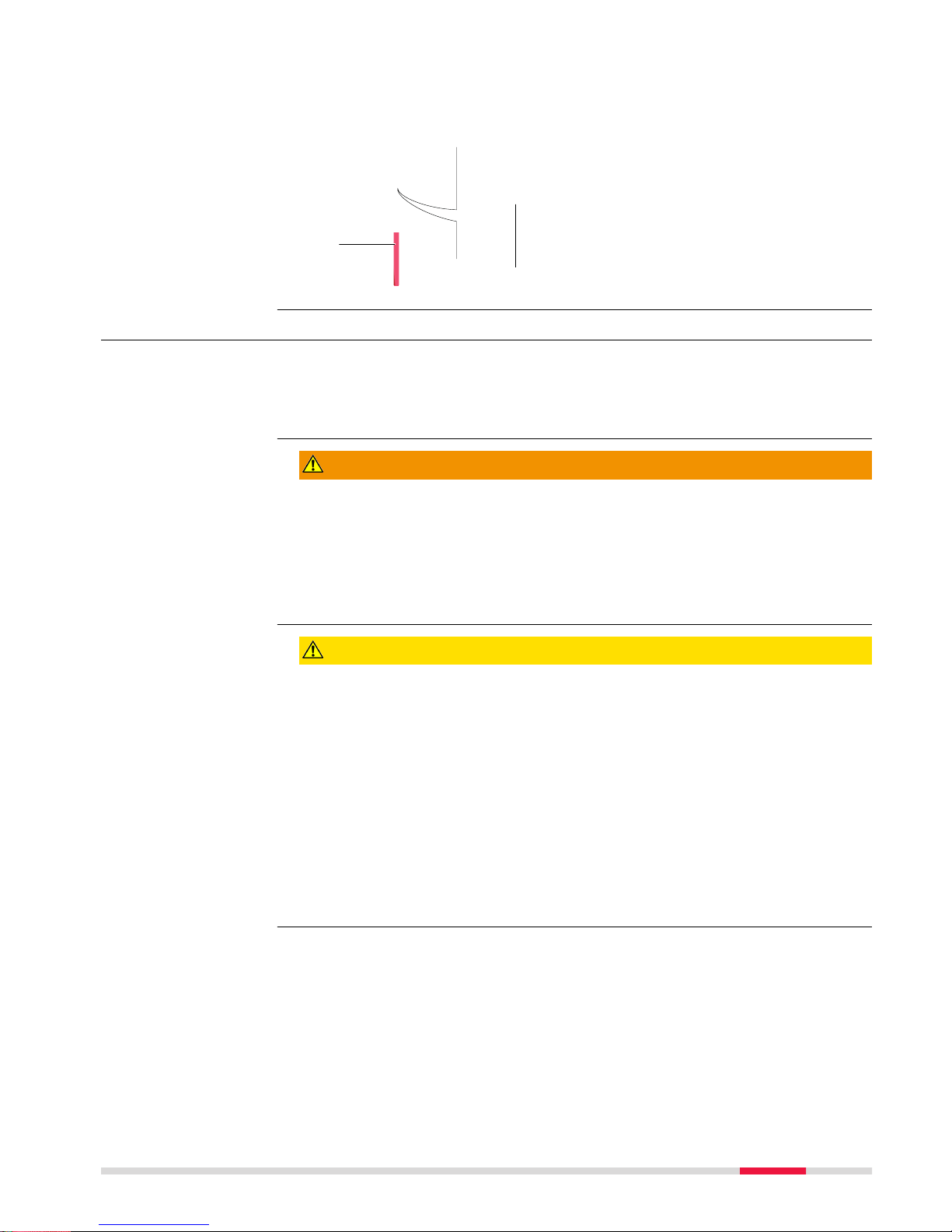
0016224_001
a
b
a Laser beam
b
Exit for laser beam
1.7 Electromagnetic Compatibility EMC
The term Electromagnetic Compatibility is taken to mean the capability of the
p
roduct to function smoothly in an environment where electromagnetic radiation and electrostatic discharges are present, and without causing electromagnetic disturbances to other equipment.
WARNING
Electromagnetic radiation
Elec
tromagnetic radiation can cause disturbances in other equipment.
Precautions:
▶
Although the product meets the strict regulations and standards which are
in force in this respect, Leica Geosystems cannot completely exclude the
possibility that other equipment may be disturbed.
CAUTION
Use of the product with accessories from other manufacturers. For
ex
ample field computers, personal computers or other electronic equip-
ment, non-standard cables or external batteries
This may cause disturbances in other equipment.
Precautions:
▶
Use only the equipment and accessories recommended by Leica Geosystems.
▶
When combined with the product, they meet the strict requirements stipulated by the guidelines and standards.
▶
When using computers, two-way radios or other electronic equipment, pay
attention to the information about electromagnetic compatibility provided
by the manufacturer.
Labelling
Description
Safety Directions 19
Page 20
CAUTION
Intense electromagnetic radiation. For example, near radio transmitters, transp
onders, two-way radios or diesel generators
Although the product meets the strict regulations and standards which are in
force in this respect, Leica Geosystems cannot completely exclude the possibility that function of the product may be disturbed in such an electromagnetic
environment.
Precautions:
▶
Check the plausibility of results obtained under these conditions.
CAUTION
Electromagnetic radiation due to improper connection of cables
If the p
roduct is operated with connecting cables attached at only one of their
two ends, for example external supply cables, interface cables, the permitted
level of electromagnetic radiation may be exceeded and the correct functioning
of other products may be impaired.
Precautions:
▶
While the product is in use, connecting cables, for example product to
external battery, product to computer, must be connected at both ends.
WARNING
Use of product with radio or digital cellular phone devices
Elec
tromagnetic fields can cause disturbances in other equipment, in installations, in medical devices, for example pacemakers or hearing aids and in aircraft. It can also affect humans and animals.
Precautions:
▶
Although the product meets the strict regulations and standards which are
in force in this respect, Leica Geosystems cannot completely exclude the
possibility that other equipment can be disturbed or that humans or animals can be affected.
▶
Do not operate the product with radio or digital cellular phone devices in
the vicinity of filling stations or chemical installations, or in other areas
where an explosion hazard exists.
▶
Do not operate the product with radio or digital cellular phone devices
near to medical equipment.
▶
Do not operate the product with radio or digital cellular phone devices in
aircraft.
1.8 FCC Statement, Applicable in U.S.
☞
The greyed paragraph below is only applicable for products without
r
adio.
20 Safety Directions
Page 21
WARNING
This equipment has been tested and found to comply with the limits for a
C
lass B digital device, pursuant to part 15 of the FCC rules.
These limits are designed to provide reasonable protection against harmful
interference in a residential installation.
This equipment generates, uses and can radiate radio frequency energy and,
if not installed and used in accordance with the instructions, may cause
harmful interference to radio communications. However, there is no guarantee that interference will not occur in a particular installation.
If this equipment does cause harmful interference to radio or television
reception, which can be determined by turning the equipment off and on,
the user is encouraged to try to correct the interference by one or more of
the following measures:
•
R
eorient or relocate the receiving antenna.
•
Increase the separation between the equipment and the receiver.
•
Connect the equipment into an outlet on a circuit different from that to
which the receiver is connected.
•
Consult the dealer or an experienced radio/TV technician for help.
CAUTION
Changes or modifications not expressly approved by Leica Geosystems for
c
ompliance could void the user's authority to operate the equipment.
Pav = 4.8mW λ = 658nm t p = 800ps
IEC 60825-1:2014
Complies wit h FDA performa nce standards f or laser produc ts except for
deviations pur suant to Laser No tice No. 50, dat ed June 24, 2007.
This device complies with part 15 of the FCC Rules.
Operation is s ubject to the foll owing two cond itions:
(1) This device may not cause harmful interference, and
(2) This devi ce must accept any i nterferenc e received, inc luding inter ference
that may cause unde sired operat ion.
123456
S.No.:
123456
Art.No.:
Equip.No.: 1234567
Power: 12-15V 12W ma x
Leica Geosystems AG
CH-9435 Heerbrugg
Manufactured: 20XX
Made in Swit zerland
TS13
Model:
0016219_001
008611_001
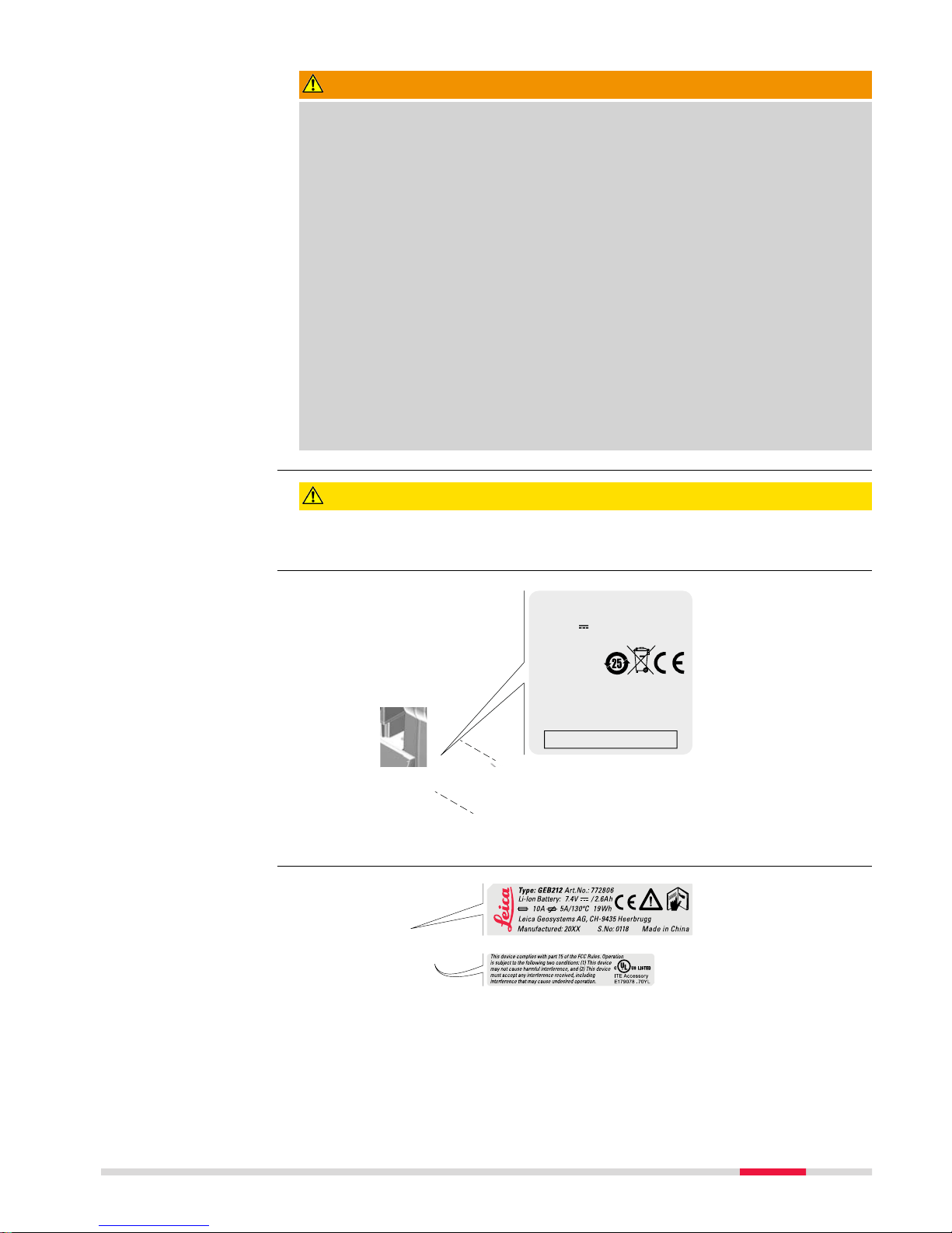
Labelling TS13
Labelling internal
battery GEB212,
GEB222
Safety Directions 21
Page 22
008610_001
RH16
Model: RH16
Art.No. : 788853
Power: 7.4V/12.5V /
0.2A max.
Leica Geosystems AG
CH-9435 Heerbrugg
Manufactured: 20XX
Made in Switzerland
Contains
Transmitter Module:
FCC ID: PHV0939
IC: 5325A-0939
S.No.: 1234567
This device complies
with part 15 of the
FCC Rules. Operation
is subject to the
following two
conditions: (1) This
device may not cause
harmful interference,
and (2) this device
must accept any
interference received,
including interference
that may cause
undesired operation.
008612_002
RH17
Model: RH17
008613_002
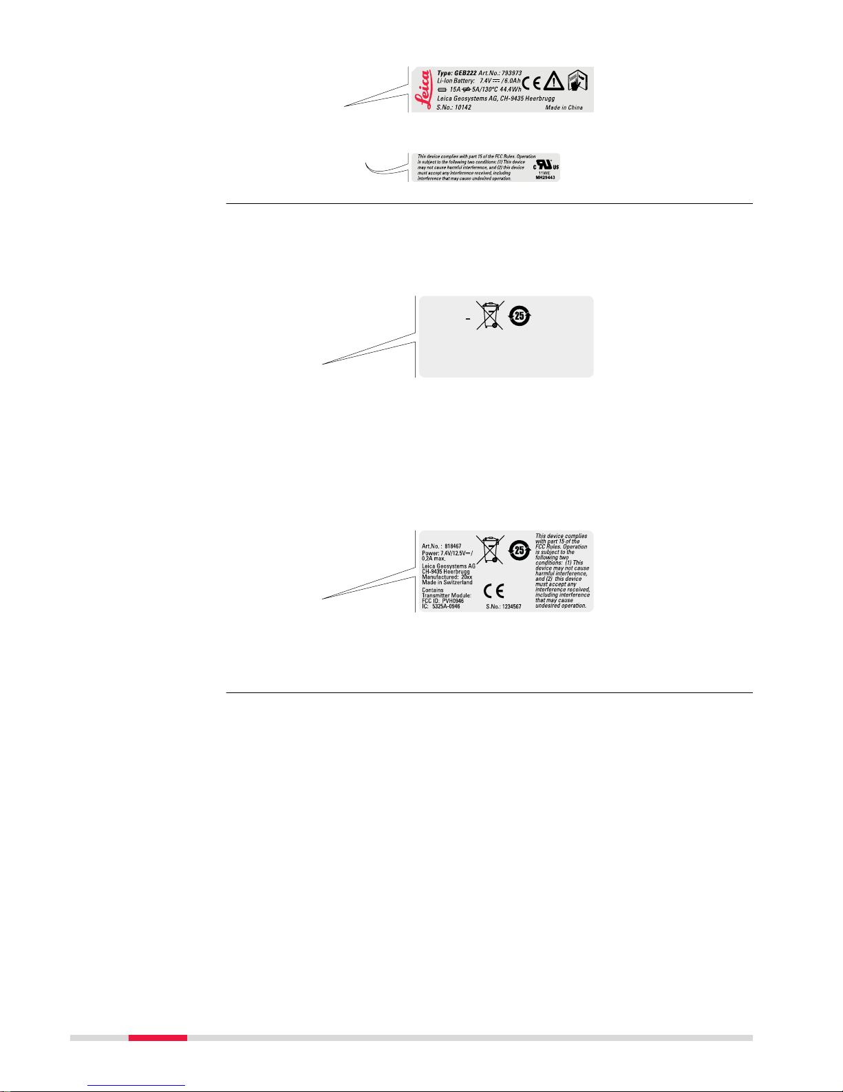
Labelling RadioHandle
22 Safety Directions
Page 23

1.9 ICES-003 Statement, Applicable in Canada
WARNING
This Class (B) digital apparatus complies with Canadian ICES-003.
Ce
t appareil numérique de la classe (B) est conforme à la norme NMB-003
du Canada.
Canada Compliance Statement
T
his device complies with Industry Canada’s license-exempt RSSs. Operation
is subject to the following two conditions:
1. This device may not cause interference; and
2. This device must accept any interference, including interference that
may cause undesired operation of the device.
Canada Déclaration de Conformité
Le présent appareil est conforme aux CNR d’Industrie Canada applicables aux
appareils radio exempts de licence. L’exploitation est autorisée aux deux conditions suivantes:
1. l’appareil ne doit pas produire de brouillage;
2. l’appareil doit accepter tout brouillage radioélectrique subi, même si le
brouillage est susceptible d’en compromettre le fonctionnement.
Safety Directions 23
Page 24

2 Description of the System
2.1 System Components
0016239_001
TS13
CS20
Component Description
TS13 instrument
•
a total station for measuring, calculating and
capturing data.
•
consisting of various models with a range of
accuracy classes.
•
integrated with an add-on GNSS system to form
SmartStation.
•
combined with the multi-purpose CS20 field controller to conduct remote control surveys.
CS20 field controller A multipurpose field controller allowing the remote
c
ontrol of the TS13 instrument.
Infinity The office software including a series of help pro-
grams which support working with Leica instruments.
The following terms and abbreviations can be found in this manual:
Term Description
Remote
Mo
de
The instrument is remote controlled by the field controller or
using radio.
EDM Electronic Distance Measurement
EDM refers to the laser distancer incorporated into the
instrument which enables distance measurement.
Two measuring modes are available:
•
Prism mode. This mode refers to the ability to measure
distances to prisms. It incorporates the long range mode
to measure extended distances to prisms.
•
Any surface mode. This mode refers to the ability to
measure distances without prisms.
PinPoint PinPoint refers to the Reflectorless EDM technology which
enables an increased measuring range with a smaller laser
spot size. Two options are available: R500 and R1000.
EGL Electronic Guide Light
Main components
Terms and
abbr
eviations
24 Description of the System
Page 25

Term Description
An EGL fitted to an instrument assists with prism targeting. It
c
onsists of two differently coloured flashing lights located in
the instrument telescope housing. The person holding the
prism can align themselves into the line-of-sight of the
instrument.
Motorised Instruments fitted with internal motors, enabling automatic
horizontal and vertical turning are referred to as Motorised.
ATR Automatic Target Aiming.
ATR refers to the instrument sensor which enables the automatic target aiming and locking.
Automated Instruments fitted with ATR are referred to as Automated.
ATR refers to the instrument sensor which enables the auto-
matic target aiming to a prism.
Three automation modes are available with Aim at target:
•
Manual: no automation and no lock.
•
Automatic: automatic target aiming to a prism.
Lock Lock is an extension of ATR. An already targeted prism will be
followed automatically. Optional.
SpeedSearch SpeedSearch refers to the instrument sensor which enables
the automatic rapid finding of a prism. Optional.
SmartStation A TS instrument integrated with an add-on GNSS system,
comprising hardware and software components, forms a
SmartStation.
Components of a SmartStation include a SmartAntenna and a
SmartAntenna Adapter.
A SmartStation provides an additional instrument setup
method for determining instrument station coordinates.
The GNSS principles and functionality of a SmartStation
derive from the principles and functionality of Leica VivaGNSS
instruments.
SmartAntenna
SmartAntenna with integrated Bluetooth is a component of a
SmartStation. It can also be used independently on a pole
with a CS20 field controller.
RadioHandle A component of remote mode is the RH16/RH17 RadioHan-
dle. It is an instrument carry handle with an integrated long
range Bluetooth module with attached antenna.
☞
The RadioHandle interface is only available if the
Robotic option is purchased.
Communication side
cover
Communication side cover with integrated Bluetooth, SD card
slot, USB port and WLAN are standard for a TS13 instrument
and a component of a SmartStation. In combination with the
RH16/RH17 RadioHandle, it is also a component of remote
mode.
☞
The RadioHandle interface is only available if the
Robotic option is purchased.
Description of the System 25
Page 26

Model TS13
Angle measurement
ü
Distance measurement to prism
ü
Distance measurement to any surface (reflectorless)
ü
Motorised
ü
Automatic Target Aiming
ü
Lock *
SpeedSearch *
RS232, USB and SD card interface
ü
Bluetooth
ü
Internal Flash Memory (2 GB)
ü
Hotshoe interface for RadioHandle *
Guide Light (EGL)
ü
WLAN
ü
Keyboard Display Unit *
ü
Standard
* Optional
2.2 System Concept
2.2.1 Software Concept
Type Firmware
Uploa
d
Application
Upload
TS13 with four button keyboard
ü
-
TS13 with keyboard display unit
ü ü
Software type Description
TS firmware
(xx.f
w)
The Leica Captivate software is running on
the TS instrument and covers all functions of
the instrument.
The main applications and languages are
integrated into the firmware and cannot be
deleted.
The languages released with Leica Captivate
are included in the firmware file.
Applications
(xx.axx)
Many optional survey-specific applications
are available for the TS instruments. All applications are included in the Leica Captivate
firmware file and can be loaded separately.
Some of the applications are activated freely
and require no licence key; others require
purchasing and are only activated with a
licence key.
Available models
Description
Software for
TS mo
dels
26 Description of the System
Page 27

Software type Description
If the licence is not loaded to the instrument,
ap
plications requiring a licence key run for a
trial period. For a trial run, the Measure&Stakeout licence must be available on
the TS.
Customised applications
(xx.axx)
Customised software, specific to user
requirements, can be developed using the
GeoC++ development kit. Information on the
GeoC++ development environment is available on request from a Leica Geosystems representative.
☞
Uploading software can take some time. Ensure that the battery is at
le
ast 75% full before you start the upload. Do not remove the battery
during the upload process.
Software update instructions for instruments with a four button keyboard without display:
1. Download the most recent firmware file from
https://myworld.leica-geosystems.com. Refer to "Introduction".
2. Copy the firmware file into the System folder on the Leica SD card.
3. Start the instrument.
4. The upload process starts automatically.
The Power LED of the keyboard unit is red during the upload and
green when the firmware update is finished.
The firmware file is renamed with a suffix "..._installed".
Software update instructions for instruments with a full keyboard and
w
ith display:
1. Download the most recent firmware file from
https://myworld.leica-geosystems.com. Refer to "Introduction".
2. Copy the firmware file into the System folder on the Leica SD card.
3. Start the instrument. Select Settings\Tools\Update software.
Select the firmware file and start the update.
4. When the update is complete, a message appears.
For instruments with a Four Button Keyboard Unit
☞
Licences are key codes to enable software functions and applications
which r
un on the instrument.
You can order new licences on myWorld or by contacting your local
service partner.
1. Store the licence key file (*.key) in the \SYSTEM folder of the SD card.
2. Insert the SD card into the TS13. Refer to "4.7 Working with the
Memory Device".
3. Turn on the TS13.
4. The licence key file is loaded automatically.
Software upload
Licence activation
Description of the System 27
Page 28

5. After successful loading, the licence key file is renamed with the suff
ix "..._loaded".
☞
If the software maintenance licence has expired:
Contact your local service partner to update the software on the
product.
☞
If the licence activation fails:
Contact your local service partner or create a new support request on
myWorld.
For instruments with a Keyboard Display Unit
R
efer to the Captivate Technical Reference Manual for information about the
license upload.
2.2.2 Power Concept
Use the batteries, chargers and accessories recommended by Leica Geosystems
t
o ensure the correct functionality of the instrument.
Model Power supply
all TS models Internally by GEB222 battery, OR
Externally by GEV52 cable and GEB371 battery.
If an external power supply is connected and the internal
ba
ttery is inserted, then the external power is used.
SmartAntenna
Internally via GEB212 battery fitted into the antenna.
2.2.3 Data Storage Concept
For instruments with a four button keyboard without display:
Da
ta storage is only possible on the connected controller. On a CS20, the avail-
able memory devices are an SD card and an internal memory.
For instruments with a keyboard display unit:
Da
ta is stored on a TS memory device. The memory device can be an SD card
or internal memory. For data transfer an USB stick can also be used.
Device Description
SD card All instruments have an SD card slot fitted as standard. An SD
car
d can be inserted and removed. Available capacity: 1 GB
and 8 GB.
USB stick All instruments have a USB port fitted as standard.
Internal
memory
All instruments have an internal memory fitted as standard.
Available capacity: 2 GB.
☞
While other SD cards/USB sticks can be used, Leica Geosystems reco
mmends to only use Leica SD cards/USB sticks and is not responsible
for data loss or any other error that can occur while using a non-Leica
SD card/USB stick.
General
Power options
Description
Memory device
28 Description of the System
Page 29
Unplugging connecting cables or removing the SD card or USB stick during the
me
asurement can cause loss of data. Only remove the SD card or USB stick or
unplug connecting cables when the TS instrument is switched off.
Data can be transferred in various ways. Refer to "4.4 Connecting to a Pers
onal Computer".
SD cards can directly be used in an OMNI drive as supplied by Leica Geosyst
ems. Other PC card drives can require an adaptor.
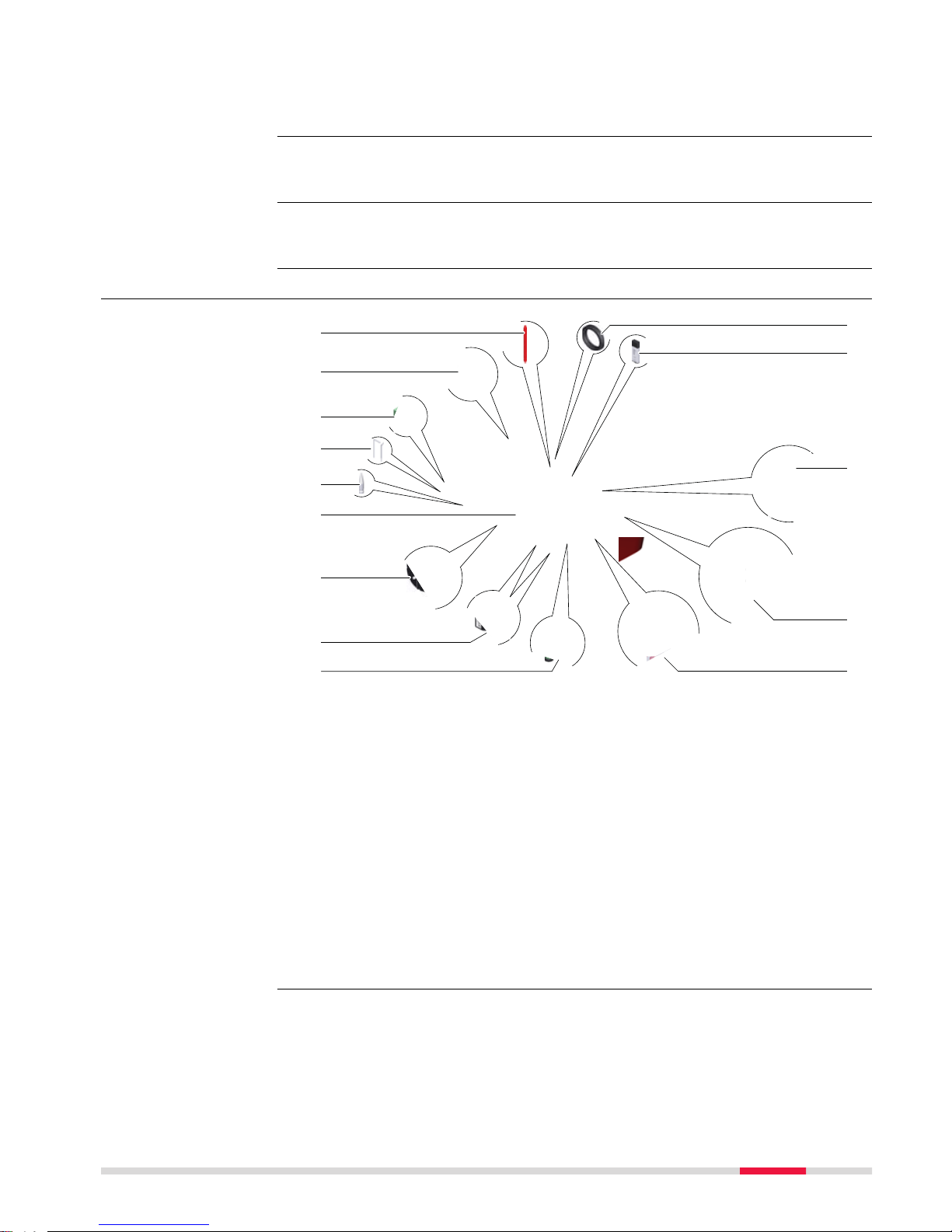
2.3 Container Contents
0016274_001
a
b
c
i
j
l
m
k
d
e
f
g
h
n
a Stylus
b GLS14 mini pole
c GHM007 Instrument height meter
d Allen key and adjustment tool
e Tip for GMP101 mini prism
f Instrument with tribrach and standard handle or RadioHandle
g GMP101 mini prism
h GEB222 batteries
i GFZ3 or GOK6 diagonal eyepiece
j Counterweight for diagonal eyepiece
k MS1, 1 GB USB memory stick
l GEV192 AC power supply for battery charger
m GRZ4 or GRZ122 prism
n Manuals and USB documentation card
☞
Transfer data
☞
Container for
ins
trument and
accessories part 1 of 2
Description of the System 29
Page 30
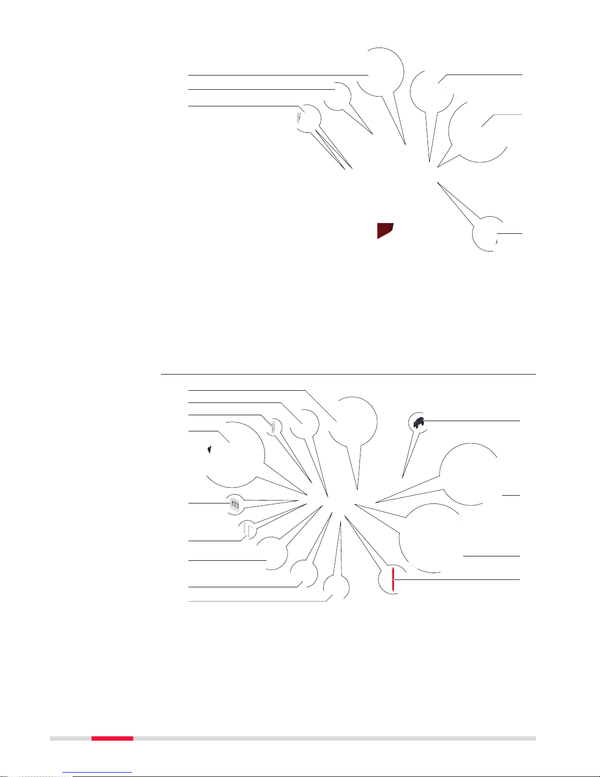
0016275_001
a
b
c
d
f
e
a Cables
b
GHT196 tribrach bracket for height meter
c SD cards and covers
d GKL311 battery charger
e Car adapter power plug for battery charger (stored under battery
charger)
f Protective cover for instrument, sunshade for objective lens and clean-
ing cloth
008620_001
a
b
c
j
l
m
k
d
e
f
g
h
i
Container for
ins
trument and
accessories part 2 of 2
Container for TS
r
obotic pole setup,
Small-Size
30 Description of the System
Page 31

a Manuals and USB documentation card
b
GAT25 radio antenna
c Mini prism spike
d GRZ4 or GRZ122 prism
e SD card and cover
f Adjustment tool and allen key
g GRZ101 mini prism and GAD103 adapter
h GEB331 battery
i GHT63 pole holder clamp
j Tip for mini pole
k GLI115 clip-on bubble for GLS115 mini prism pole
l CS20 field controller and GHT66 holder
m Stylus
2.4 Instrument Components
0016240_001
abcedgf
ij kh l
a Carry handle
b
Optical sight
c Telescope with integrated EDM, ATR, EGL,
SpeedSearch*
d EGL flashing diode - yellow and red
e SpeedSearch, transmitter
f SpeedSearch, receiver
g Coaxial optics for angle and distance
measurement, and exit port of visible
laser beam for distance measurements
h SD Card and USB stick
i Loudspeaker
j Horizontal drive
k Tribrach footscrew
l Tribrach securing screw
* optional
0016245_002
ab
e
f
cd
g
a Vertical drive
b
Focusing ring
c Interchangeable eyepiece
d Circular level
e Battery compartment
f Four button keyboard unit
g Keyboard display unit*
* optional
Instrument
comp
onents -
part 1 of 2
Instrument
comp
onents -
part 2 of 2
Description of the System 31
Page 32

0016246_001
a
b
c
d
e
a Compartment lid
b
USB stick cap storage
c USB device port (mini AB OTG)
d USB host port for USB stick
e SD card port
016512_001
a
b
c
a GS14/GS16 SmartAntenna
b
GAD110 SmartAntenna
Adapter
c Communication side cover
008625_001
a
b
a RadioHandle
b
Communication side cover
with radio handle interface*
* optional
Communication Side
Cover
Instrument
comp
onents for
SmartStation
Instrument
comp
onents for
remote mode
32 Description of the System
Page 33
3 User Interface
3.1 Keyboard
The TS13 basic variant has a four button keyboard unit without display. The
basic var
iant can be upgraded with a keyboard display unit. Both variants can
be upgraded with purchased options that enable Lock, SpeedSearch and the
RadioHandle interface on the instrument.
3.1.1 Four Button Keyboard Unit
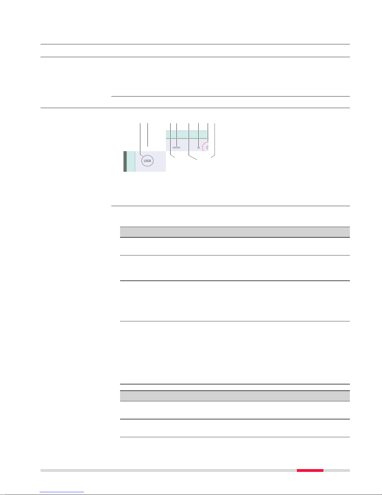
0016249_001
ba
gh
d
c
f
e
a LOCK key
b
LED for locking status
c MEAS key
d LED for measurement status
e LED for communication status
f LED for power status
g ON/OFF key
h COM key
☞
The following description of key functions and LED behaviours applies
t
o the TS13 being connected to a field controller.
Key functions
LOCK
•
Pr
ess to start prism search and lock onto prism.
•
If already locked: Press to unlock from prism.
MEAS
•
Depending on the currently active settings and field controller application:
Press to start a measurement or to store a measurement.
ON/OFF
•
Press for 2 s to turn on the instrument.
•
Press and hold for more than 2 s to shut down the instrument.
•
Press and hold for more than 5 s to reset the sensor.
•
Press and hold for more than 8 s to do a hard shutdown.
COM
•
To toggle through the communication modes, press the key
repeatedly.
Communication modes:
-
RS232
-
Bluetooth
-
Long-range Bluetooth
•
Press and hold for more than 5 s to change between CS controller and Geocom connection.
LED behaviours
LOCK
•
Of
f: Prism not locked.
•
Solid green: Prism found and locked.
MEAS
•
Off: No active measurement.
•
Solid green: Measurement is executed.
Description
Four button keyboard
w
ithout display
TS13 key functions
an
d LED behaviour
User Interface 33
Page 34
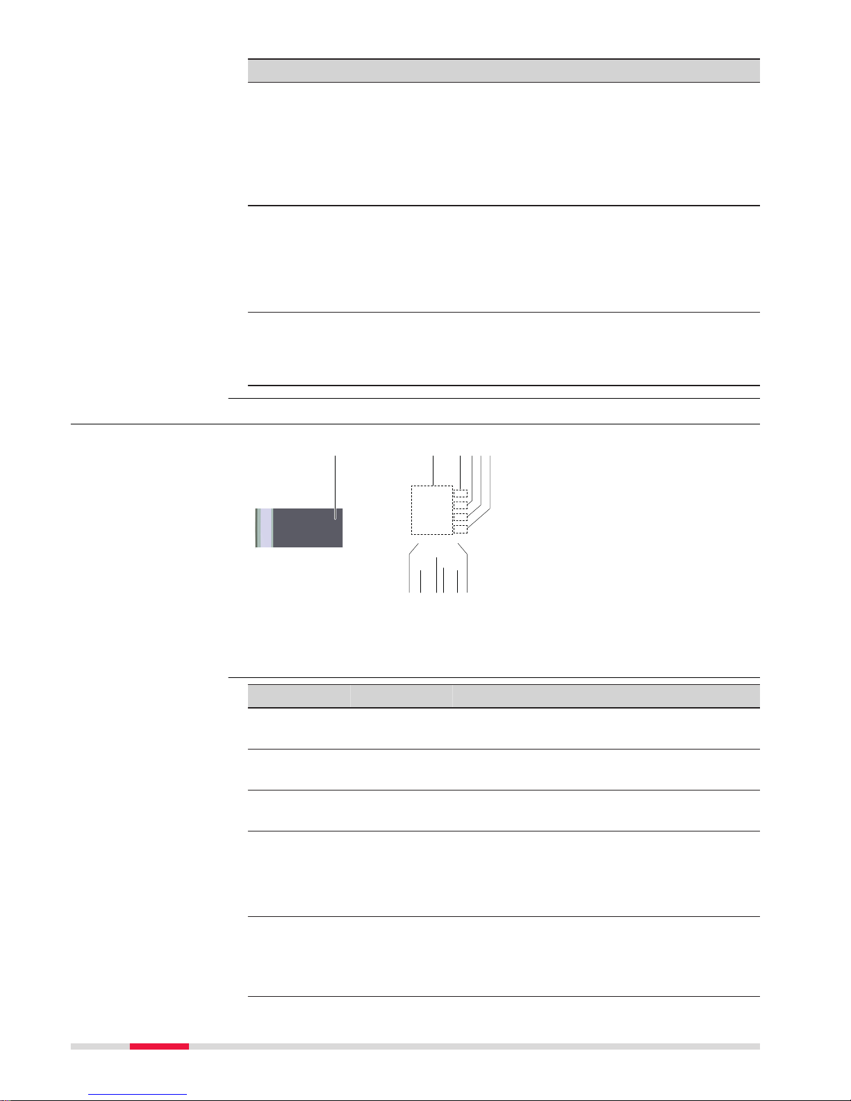
LED behaviours
ON/OFF
•
Of
f: Instrument is switched off.
•
Solid red after switching on: Instrument is booting.
•
Solid green/yellow/red: Indicator for the battery status.
-
Green: More than 40% of battery charge remaining.
-
Yellow: More than 20% of battery charge remaining.
-
Red: Remaining battery charge is very low.
•
Flashing green: Instrument is shutting down.
COM
•
Off: RS232 Serial port selected.
•
Solid green: Internal Bluetooth selected.
•
Solid red: Long-range Bluetooth using RadioHandle is selected.
•
Solid blue: Bluetooth communication established to CS controller using Internal Bluetooth or long-range Bluetooth.
LOCK,
M
EAS
and COM
together
•
Solid gr
een/red: Changing between CS controller and Geo-
com connection.
•
Solid red: Reset process of the system is started.
3.1.2 Keyboard Display Unit
0016284
a
hg ki j
b c dle f
a Display
b
Alphanumeric keys
c ON/OFF
d Backspace
e Favourites
f Home
g Esc
h Fn
i OK
j Arrow keys
k Enter
l Camera*
* Not applicable
Key Function
Alphanumeric
k
eys
To type letters and numbers.
Esc Leaves the current screen without storing
an
y changes.
Fn
Switches between first and second level of
an
y key on the keyboard.
Enter
Selects the highlighted line and leads to the
nex
t logical menu / dialog.
Starts the edit mode for editable fields.
Opens a selectable list.
ON/OFF
If the instrument is already off: Turns on the
ins
trument when held for 2 s.
If the instrument is already on: Turns to
P
ower Options menu when held for 2 s.
Keyboard display unit
Keys
34 User Interface
Page 35

Key Function
Favourites Goes to a favourites menu.
Home Switches to the Home Menu.
Arrow keys Move the focus on the screen.
OK Selects the highlighted line and leads to the
nex
t logical menu / dialog.
Starts the edit mode for editable fields.
Opens a selectable list.
Backspace
Deletes the job in the centre of the job carous
el.
Key Function
+ Hold Fn while p
ressing
.
Swit
ch to Windows.
+ Hold Fn while p
ressing
.
T
ake a screenshot of the current screen.
+ Hold Fn while p
ressing 1.
Increase the screen brightness.
+ Hold Fn while p
ressing 4.
Decrease the screen brightness.
+ Hold Fn while p
ressing 3.
Increase the volume for acoustic warning signals, beeps and keypresses on the instrument.
+ Hold Fn while p
ressing 6.
Decrease the volume for acoustic warning
signals, beeps and keypresses on the instrument.
+ Hold Fn while p
ressing 7.
Lock/unlock the keyboard.
+ Hold Fn while p
ressing 9.
Lock/unlock the touch screen.
+ Hold Fn while pressing .
Enter a plus sign instead of a minus sign.
+ Hold Fn while p
ressing
.
T
urn the keyboard illumination on/off.
3.2 Operating Principles
Refer to Four Button Keyboard Unit for the operating principles of the four butt
on keyboard.
Key combinations
☞
User Interface 35
Page 36

The user interface is operated either by the keyboard or by the touch screen
with sup
plied stylus. The workflow is the same for keyboard and touch screen
entry, the only difference lies in the way information is selected and entered.
Operation by keyboard
Information is selected and entered using the keys.
Operation by touch screen
Information is selected and entered on the screen using the supplied stylus.
Operation Description
To select an item Tap on the item.
To start the edit mode in editable
f
ields
Tap on the editable field.
To highlight an item or parts of it for
editing
Drag the supplied stylus from the left
to the right.
To accept data entered into an editable field and exit the edit mode
Tap on the screen outside of the
editable field.
To open a context-sensitive menu Tap on the item and hold for 2 s.
Keyboard and touch
scr
een
36 User Interface
Page 37
4 Operation
4.1 Setting Up the TS Instrument
5
5
5
c
b
a
7
4/6
1
1
1
3
2
0016251_001
☞
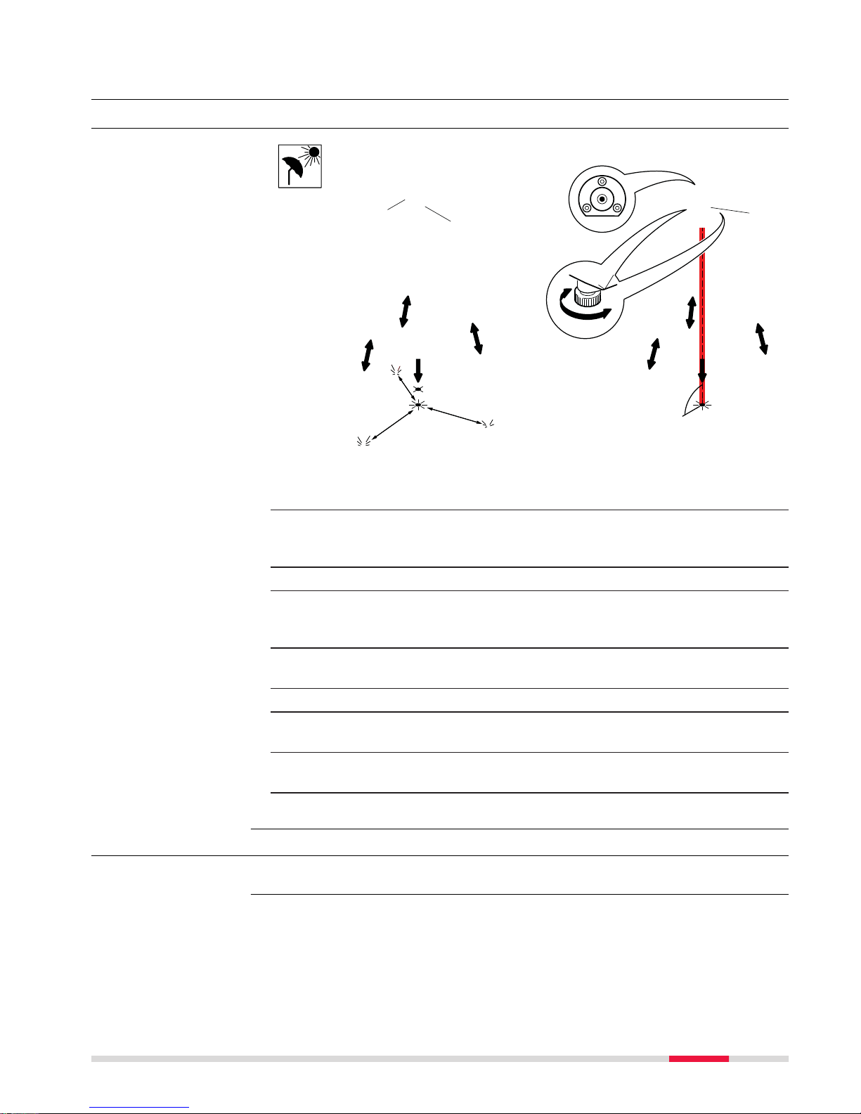
Shield the instrument from direct sunlight and avoid uneven tempera
tures around the instrument.
1. Extend the tripod legs to allow for a comfortable working posture.
Position the tripod above the marked ground point, centring it as
good as possible. Ensure that the tripod plate is roughly horizontal.
2. Fasten the tribrach and instrument onto the tripod.
3. Turn on the instrument by pressing
. Select Se
ttings/TS instru-
ment/Level & compensator to activate the laser plummet and
electronic level.
4. Use the tribrach footscrews (a) to centre the plummet (b) above the
ground point.
5. Adjust the tripod legs to level the circular level (c).
6. By using the electronic level, turn the tribrach footscrews (a) to level
the instrument precisely.
7. Centre the instrument precisely over the ground point (b) by shifting
the tribrach on the tripod plate.
8. Repeat steps 6. and 7. until the required accuracy is achieved.
4.2 Setting up for Remote Control (with the RadioHandle)
For this functionality, the TS13 Robotic licence must be purchased.
Instrument setup
s
tep-by-step
Availability
Operation 37
Page 38
0016831_001
b
c
☞
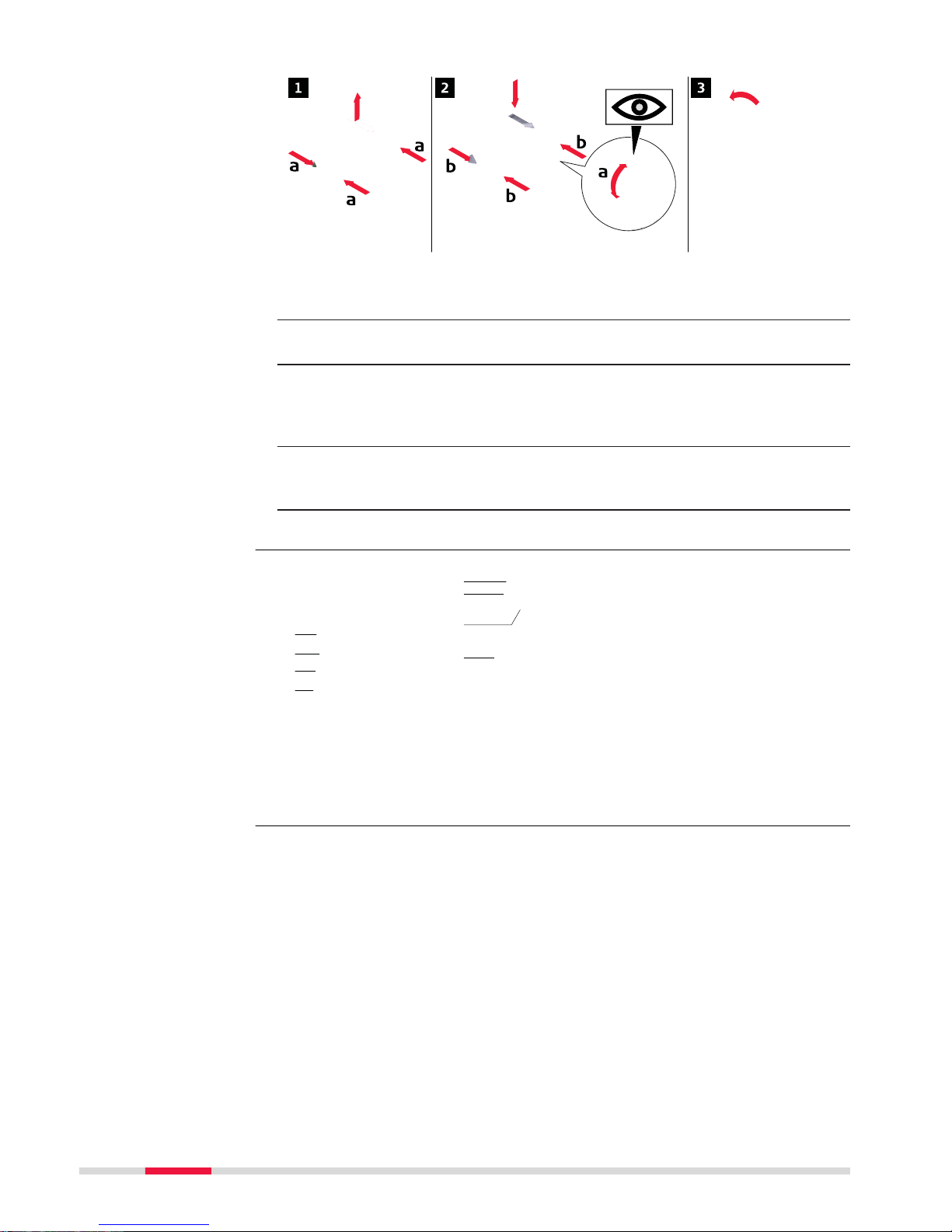
Refer to "4.1 Setting Up the TS Instrument" for the initial instrument
setup onto a tripod.
1. To remove the instrument carry handle: Press and hold the four
unlock push buttons and lift off the handle.
2. To install the RadioHandle, first make sure that the interface connection on the lower part of the handle is on the same side as the Communication side cover. Then press and hold the four unlock push
buttons and attach the handle.
☞
Ensure that there is a tight fit with the instrument after releasing the
push buttons. If no connection can be found, re-check that handle is
seated firmly.
3. Swing the antenna of the RadioHandle into an upright position.
0016254_001
a
b
c
d
e
f
g
h
a 360° prism
b
Prism pole
c Field controller on
GHT66 holder (Alternative,
not illustrated: tablet on
GHT78 holder)
d GHT63 clamp
e RH16/RH17 RadioHandle
f Instrument
g Communication side cover
h Tripod
Attaching the RadioHan
dle step-by-step
Setup for remote
con
trol with
RadioHandle
38 Operation
Page 39
4.3 Fixing the Field Controller to a Holder and Pole
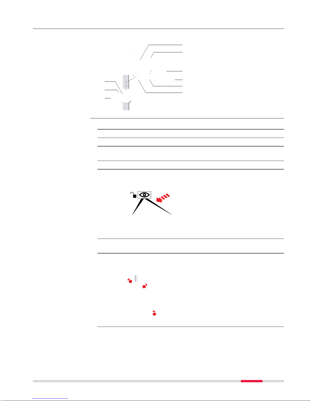
The GHT66 holder consists of the following components:
008545_001
a
b
c
f
d
e
g
h
i
GHT63 clamp
a Plastic sleeve
b
Pole clamp
c Clamp bolt
GHT66 holder
d Locking pin
e Top clip
f Mounting plate
g Bottom clip
h Tightening screw
i Mounting arm
☞
For an aluminium pole, fit the plastic sleeve to the pole clamp.
1. Insert the pole into the clamp hole.
2. Attach the holder to the clamp using the clamp bolt.
3. Adjust the angle and the height of the holder on the pole to a comf
ortable position.
4. Tighten the clamp with the clamp bolt.
5. Before placing the CS field controller onto the mounting plate, ensure
that the locking pin is put into the unlocked position. To unlock the
locking pin, push the locking pin to the left.
008546_001
6. Hold the CS field controller above the holder and lower the end of
the CS f
ield controller into the mounting plate.
7. Apply slight pressure in a downward direction and then lower the top
part of the CS field controller until the unit is clicked into the holder.
The guides of the mounting plate aid in this action.
7c
7a
7b
008547_001
Components of the
G
HT66 holder
Fixing the field
controller and GHT66
to a pole step-bystep
Operation 39
Page 40
8. After the CS field controller is placed onto the mounting plate,
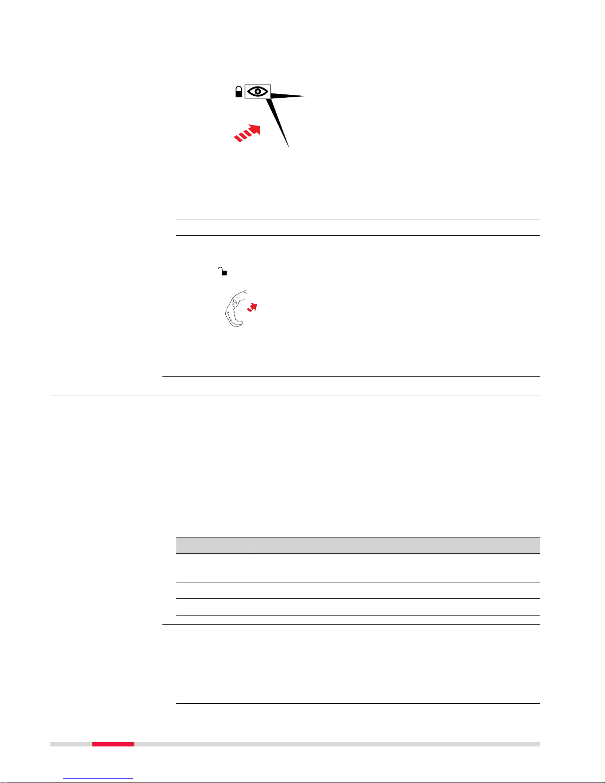
ensur
e that the locking pin is put into the locked position. To lock
the locking pin, push the locking pin to the right.
008549_001
1. Unlock the locking pin by pushing the locking pin to the left of the
moun
ting plate.
2. Place your palm over the top of the field controller.
3. While in this position, lift the top of the field controller from the
holder.
2
3
1
008551_001
4.4 Connecting to a Personal Computer
Windows Mobile De
vice Center for PCs with Windows 7/Windows 8/
Windows 10 operating system is the synchronization software for Windows
mobile-based pocket PCs. WMDC enables a PC and a Windows mobile-based
pocket PC to communicate.
Leica USB drivers support Windows 7, Windows 8 (8.1) and Windows 10 opera
ting systems.
Cables
Leica USB dr
ivers support:
Name Description
GEV223 USB data cable, 1.8 m, connects instrument to Mini-USB to
USB
GEV234 USB data cable, 1.65 m, connects CS to GS or CS to PC (USB)
GEV261 Y-cable, 1.8 m, connects instrument to PC – battery
☞
Skip the following steps if you have never installed Leica USB drivers
b
efore.
If older drivers were previously installed on the PC, follow the instructions to
unins
tall the drivers prior the installation of the new drivers.
1. Connect your instrument to the PC via cable.
Detaching the field
con
troller from a pole
step-by-step
Description
Uninstalling the
pr
evious drivers
40 Operation
Page 41

2. On your PC, select to Con
trol Panel > Device Manager.
3. In Network Adapters, right-click on Remote NDIS based LGS….
4. Click on Uninstall.
5. Set Dele
te the driver… as checked. Press OK.
1. Start the PC.
2. Run the Se
tup_Leica_USB_XXbit.exe to install the drivers necessary
for Leica devices. Depending on the version (32bit or 64bit) of the
operating system on your PC, you have to select between the three
setup files following:
•
Setup_Leica_USB_32bit.exe
•
Setup_Leica_USB_64bit.exe
•
Setup_Leica_USB_64bit_itanium.exe
☞
To check the version of your operating system, go to Control Panel > System > System type.
☞
The setup requires administrative privileges.
☞
The setup has to be run only once for all Leica devices.
3. The Welcome to InstallShield Wizard for Leica GS, TS/TM/MS,
CS and GR USB drivers window appears.
☞
Ensure that all Leica devices are disconnected from your PC
before you continue!
Install Leica USB
drivers
Operation 41
Page 42

4. Next>.
5. The Ready to Install the Program window appears.
6. Install. T
he drivers will be installed on your PC.
7. The InstallShield Wizard Completed window appears.
8. Click Finish to exit the wizard.
1. Start the PC.
2. Plug the cable into the instrument.
3. Turn on the instrument.
4. Plug the cable into the USB port of the PC.
5. Press the Windows Start button at the bottom left corner of the
s
creen.
6. Type the IP address of the device into the search field.
•
\\192.168.254.1
\ for field controller
•
\\192.168.254.3\ for other instruments
7. Press En
ter.
Connect to PC via USB
c
able step-by-step
42 Operation
Page 43

A file browser opens. You can now browse within the folders on the
ins
trument.
4.5 Power Functions
Option Key Description
Turn on ON/OFF Press and hold for 2 s.
☞
The instrument must have a power
sup
ply.
Turn off ON/OFF Press and hold for 2 s.
☞
For instruments set up in permanent installations with external
power sources, for example monitoring, ensure external power
remains available until the instrument has successfully completed
the power down process.
Reset ON/OFF Press and hold for more than 5 s.
Parts of the internal memory are reset.
Hard
shutdown
ON/OFF Press and hold for more than 8 s.
4.6 Batteries
4.6.1 Operating Principles
•
T
he battery must be charged before using it for the first time because it is
delivered with an energy content as low as possible.
•
The permissible temperature range for charging is from 0 °C to +40 °C/
+32 °F to +104 °F. For optimal charging, we recommend charging the batteries at a low ambient temperature of +10 °C to +20 °C/+50 °F to +68 °F
if possible.
•
It is normal for the battery to become warm during charging. Using the
chargers recommended by Leica Geosystems, it is not possible to charge
the battery once the temperature is too high.
•
For new batteries or batteries that have been stored for a long time
(> three months), it is effectual to make only one charge/discharge cycle.
•
For Li-Ion batteries, a single discharging and charging cycle is sufficient. We
recommend carrying out the process when the battery capacity indicated
on the charger or on a Leica Geosystems product deviates significantly
from the actual battery capacity available.
•
T
he batteries can be operated from −20 °C to +55 °C/−4 °F to +131 °F.
•
Low operating temperatures reduce the capacity that can be drawn; high
operating temperatures reduce the service life of the battery.
Power functions
First-time use/
c
harging batteries
Operation/
disc
harging
Operation 43
Page 44
4.6.2 Battery for the TS Instrument
1
7
2
6
3
4
5
0016256_001
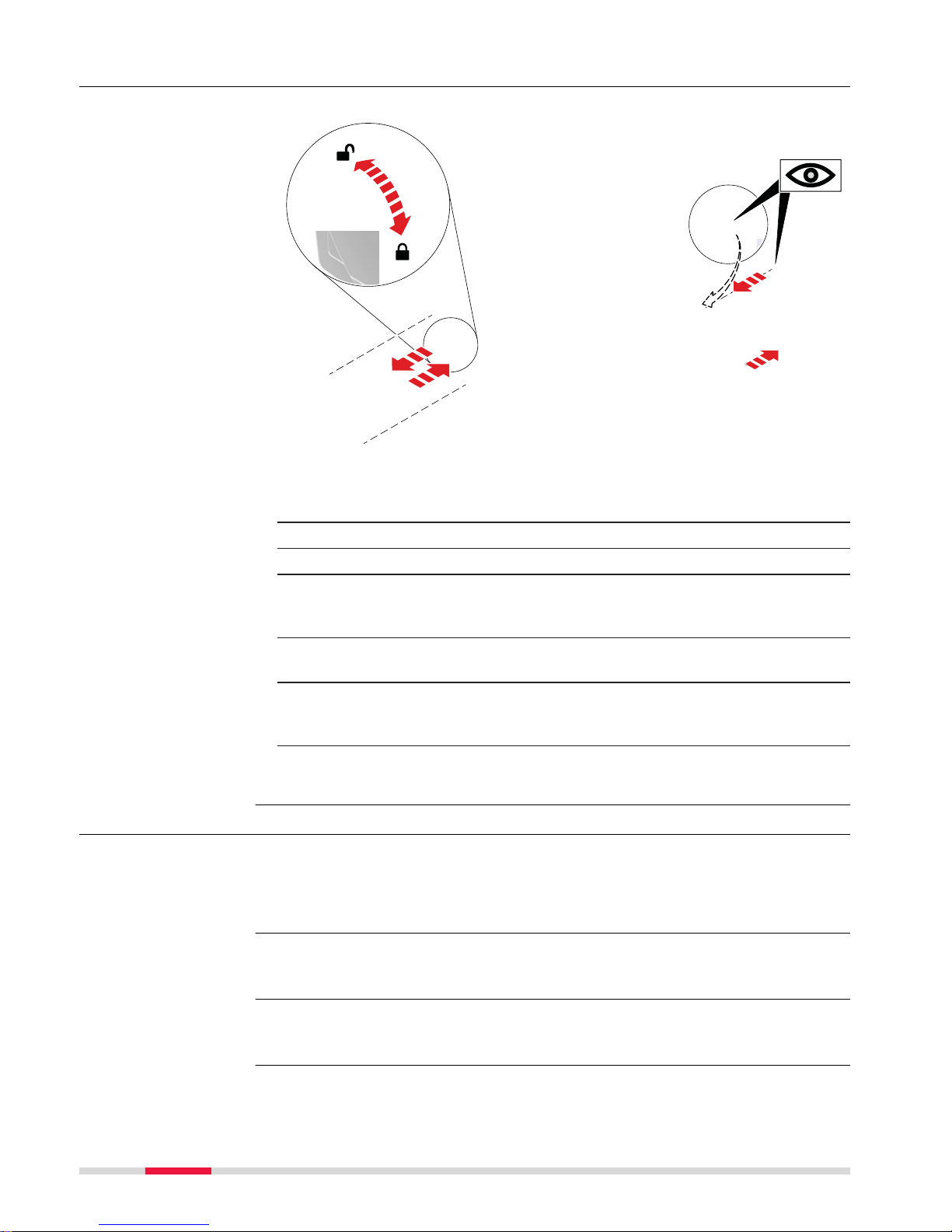
1. Face the instrument so that the vertical drive screw is on the left.
T
he battery compartment is below the vertical drive. Turn the knob to
the vertical position, opening the lid of the battery compartment.
2. Pull out the battery housing.
3. Pull the battery out of the battery housing.
4. At the top of the battery is a notch which corresponds to the inner
surface of the battery housing. This notch helps you to place the
battery correctly.
5. Place the battery into the battery housing, ensuring that the contacts
are facing outward. Click the battery into position.
6. Place the battery housing into the battery compartment. Push the
battery housing in until it fits completely into the battery compartment.
7. Turn the knob to lock the battery compartment. Ensure that the knob
is returned to its original horizontal position.
4.7 Working with the Memory Device
•
K
eep the card dry.
•
Use it only within the specified temperature range.
•
Do not bend the card.
•
Protect the card from direct impacts.
Failure to follow these instructions could result in data loss and/or permanent
damage t
o the card.
The TS13 with the four button keyboard and without display uses the memor
ies only for firmware/license key upload.
Change battery stepby-s
tep
☞
☞
☞
44 Operation
Page 45
1
4b
0016257_001
2
3
4a
(5)
☞
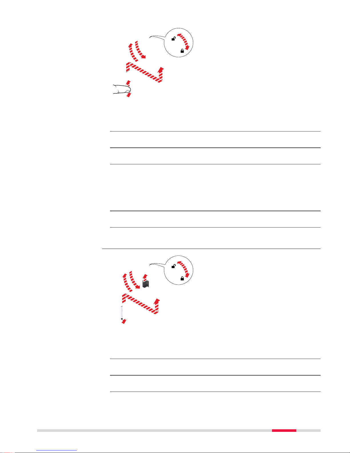
The SD card is inserted into a slot inside the Communication side
c
over of the instrument.
1. Turn the knob on the Communication side cover to the vertical position to unlock the communication compartment.
2. Open the lid of the communication compartment to access the communication ports.
3. To insert the SD card, slide it firmly into the SD slot until it clicks into
position.
☞
The card must be held with the contacts at the top and
facing toward the instrument.
☞
Do not force the card into the slot.
4. Close the lid and turn the knob to the horizontal position to lock the
communication compartment.
5. To remove the SD card, gently press on the top of the card to release
it from the slot.
1
5b
0016273_001
2
3
4
5a
(6)
☞
The USB stick is inserted into the USB host port inside the Communica
tion side cover of the instrument.
1. Turn the knob on the Communication side cover to the vertical position to unlock the communication compartment.
2. Open the lid of the communication compartment to access the communication ports.
3. Slide the USB stick with the Leica logo facing you firmly into the USB
host port until it clicks into position.
Insert and remove an
SD c
ard step-by-step
Insert and remove a
USB s
tick step-by-
step
Operation 45
Page 46

☞
Do not force the USB stick into the port.
4. If desired, store the lid of the USB stick on the underside of the compar
tment lid.
5. Close the lid and turn the knob to the horizontal position to lock the
compartment.
6. To remove the USB stick, open the lid of the compartment and slide
the USB stick out of the port.
4.8 LED Indicators
Description
T
he RadioHandle has Light Emitting Diode indicators. They indicate the basic
RadioHandle status.
Diagram of the LED Indicators
008660_001
abcd
a Power LED
b
Link LED
c Data Transfer LED
d Mode LED
Description of the LED Indicators
IF the is THEN
Power LED off power is off.
green power is on.
Link LED off no radio link to field controller.
red radio link to field controller.
Data Transfer
LED
off no data transfer to/from field controller.
green or
gr
een
flashing
data transfer to/from field controller.
Mode LED off data mode.
red configuration mode.
LED indicators on
Ra
dioHandle
46 Operation
Page 47
4.9 Guidelines for Correct Results
002410_002
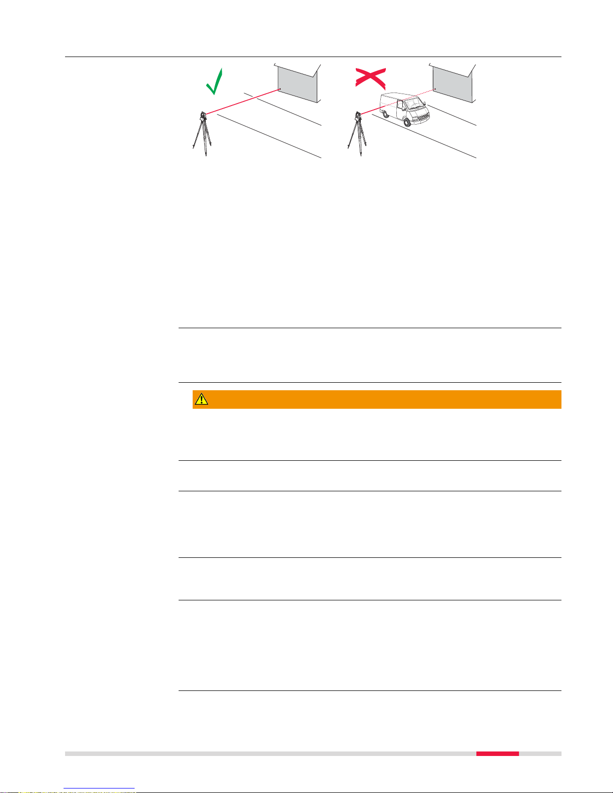
When measurements are being made using the red laser EDM, the results can
b
e influenced by objects passing between the EDM and the intended target
surface. This occurs because reflectorless measurements are made to the first
surface returning sufficient energy to allow the measurement to take place. For
example, if the intended target surface is the surface of a building, but a vehicle passes between the EDM and the target surface as the measurement is
triggered, the measurement may be made to the side of the vehicle. The result
is the distance to the vehicle, not to the surface of the building.
If using the long range measurement mode (> 1000 m, > 3300 ft) to prisms,
and an object passes within 30 m of the EDM as the measurement is triggered,
the distance measurement may be similarly effected due to the strength of the
laser signal.
Very short distances can also be measured reflectorless in Prism mo
de to well
reflecting natural targets. The distances are corrected with the additive constant defined for the active reflector.
WARNING
Due to laser safety regulations and measuring accuracy, using the Long Range
R
eflectorless EDM is only allowed to prisms that are more than 1000m (3300ft)
away.
Accurate measurements to prisms should be made in Prism mo
de.
When a distance measurement is triggered, the EDM measures to the object
which is in the b
eam path at that moment. If a temporary obstruction, for
example a passing vehicle, heavy rain, fog or snow is between the instrument
and the point to be measured, the EDM may measure to the obstruction.
Do not measure with two instruments to the same target simultaneously to
av
oid getting mixed return signals.
Instruments equipped with an ATR sensor permit automatic angle and distance
me
asurements to prisms. The prism is sighted with the optical sight. After initiating a distance measurement, the instrument sights the prism centre automatically. Vertical and horizontal angles and the distance are measured to the
centre of the prism. The lock mode enables the instrument to follow a moving
prism.
Distance
m
easurement
☞
☞
☞
☞
ATR/Lock
Operation 47
Page 48

As with all other instrument errors, the collimation error of the automatic aiming mus
t be redetermined periodically. Refer to "5 Check & Adjust" about
checking and adjusting instruments.
When a measurement is triggered while the prism is still moving, distance and
ang
le measurements may not be made for the same position and coordinates
may vary.
If the prism location is changed too quickly, the target may be lost. Make sure
tha
t the speed does not exceed the figure given in the technical data.
☞
☞
☞
48 Operation
Page 49

5 Check & Adjust
5.1 Overview
Leica Geosystems instruments are manufactured, assembled and adjusted to
the b
est possible quality. Quick temperature changes, shock or stress can
cause deviations and decrease the instrument accuracy. It is therefore recommended to check and adjust the instrument from time to time. This check and
adjust can be done in the field by running through specific measurement procedures. The procedures are guided and must be followed carefully and precisely as described in the following chapters. Some other instrument errors and
mechanical parts can be adjusted mechanically.
For a TS13 basic variant, Check & Adjust must be done remotely using a CS20.
The following instrument errors can be checked and adjusted electronically:
Instrument error Description
l, t Compensator longitudinal and transversal index
er
rors
i Vertical index error, related to the standing axis
c Horizontal collimation error, also called line of
sight error
a Tilting axis error
ATR ATR zero point error for Hz and V
If the compensator and the horizontal corrections are activated in the instrumen
t configuration, every angle measured in the daily work is corrected automatically. Check whether the tilt correction and the horizontal correction are
turned on.
The results are displayed as errors but used with the opposite sign as corrections when applied to measurements.
The following instrument parts can be adjusted mechanically:
•
C
ircular level on instrument and tribrach
•
Optical plummet - option on tribrach
•
Allen screws on tripod
To get precise measurements in the daily work, it is important:
•
T
o check and adjust the instrument from time to time.
•
To take high precision measurements during the check and adjust proce-
dures.
•
To measure targets in two faces. Some of the instrument errors are elimi-
nated by averaging the angles from both faces.
During the manufacturing process, the instrument errors are carefully determined and s
et to zero. As mentioned above, these errors can change and it is
highly recommended to redetermine them in the following situations:
Description
☞
Electronic adjustment
Mechanical
adjustment
Precise
measurements
☞
Check & Adjust 49
Page 50
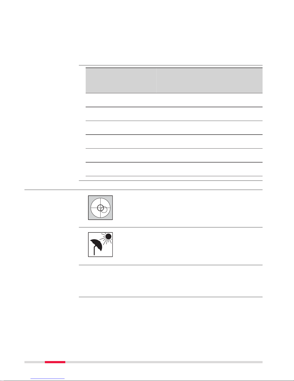
•
Be
fore the first use
•
Before every high precision survey
•
After rough or long transportation
•
After long working periods
•
After long storage periods
•
If the temperature difference between current environment and the temperature at the last calibration is more than 20°C
Instrument
err
or
EffectsHzEffectsVElimination
with two face
measurement
Automatically
corrected
with proper
adjustment
c - Line of sight
error
ü
-
ü ü
a - Tilting axis
error
ü
-
ü ü
l - Compensator
index error
-
ü ü ü
t - Compensator
index error
ü
-
ü ü
i - Vertical index
error
-
ü ü ü
ATR Collimation
error
ü ü
-
ü
5.2 Preparation
Before determining the instrument errors, the instrument has to
b
e levelled using the electronic level.
The tribrach, the tripod and the underground should be stable
and secure from vibrations or other disturbances.
The instrument should be protected from direct sunlight to
avoid thermal warming.
It is also recommended to avoid strong heat shimmer and air
turbulence. The best conditions are early in the morning or with
overcast sky.
Before starting to work, the instrument has to become acclimatised to the
ambient temperature. Approximately two minutes per °C of temperature difference from storage to working environment, but at least 15 min, should be
taken into account.
Even after adjustment of the ATR, the crosshairs may not be positioned exactly
o
n the centre of the prism after an ATR measurement has been completed.
This outcome is a normal effect. To speed up the ATR measurement, the telescope is normally not positioned exactly on the centre of the prism. These
small deviations/ATR offsets, are calculated individually for each measurement
and corrected electronically. This means that the horizontal and vertical angles
Summary of errors to
be a
djusted
electronically
☞
☞
☞
☞
50 Check & Adjust
Page 51

are corrected twice: first by the determined ATR errors for Hz and V, and then
b
y the individual small deviations of the current aiming.
IF the task is to THEN
adjust a combination of
ins
trument errors
Refer to "5.3 Combined Adjustment (l, t, i, c
and ATR)".
adjust the tilting axis Refer to "5.4 Tilting Axis Adjustment (a)".
adjust the circular level Refer to "5.5 Adjusting the Circular Level of
the Instrument and Tribrach".
adjust the laser/optical plummet
Refer to "5.7 Inspecting the Laser Plummet
of the Instrument".
adjust the tripod Refer to "5.8 Servicing the Tripod".
5.3 Combined Adjustment
(l, t, i, c an
d ATR)
The combined adjustment procedure determines the following instrument
er
rors in one process:
Instrument error Description
l, t Compensator longitudinal and transversal index
er
rors
i Vertical index error, related to the standing axis
c Horizontal collimation error, also called line of
sight error
ATR Hz ATR zero point error for horizontal angle option
ATR V ATR zero point error for vertical angle option
The following table explains the most common settings.
1. Leica Captivate - Home: Se
ttings\TS instrument\Check & adjust
2. Check & Adjust
Select the option: Check & adjust the compensator, index error,
line of sight error & automatic target aiming
3. Next
4. Face I measurement
Next step
Description
Combined adjustment
pr
ocedure step-by-
step
Check & Adjust 51
Page 52
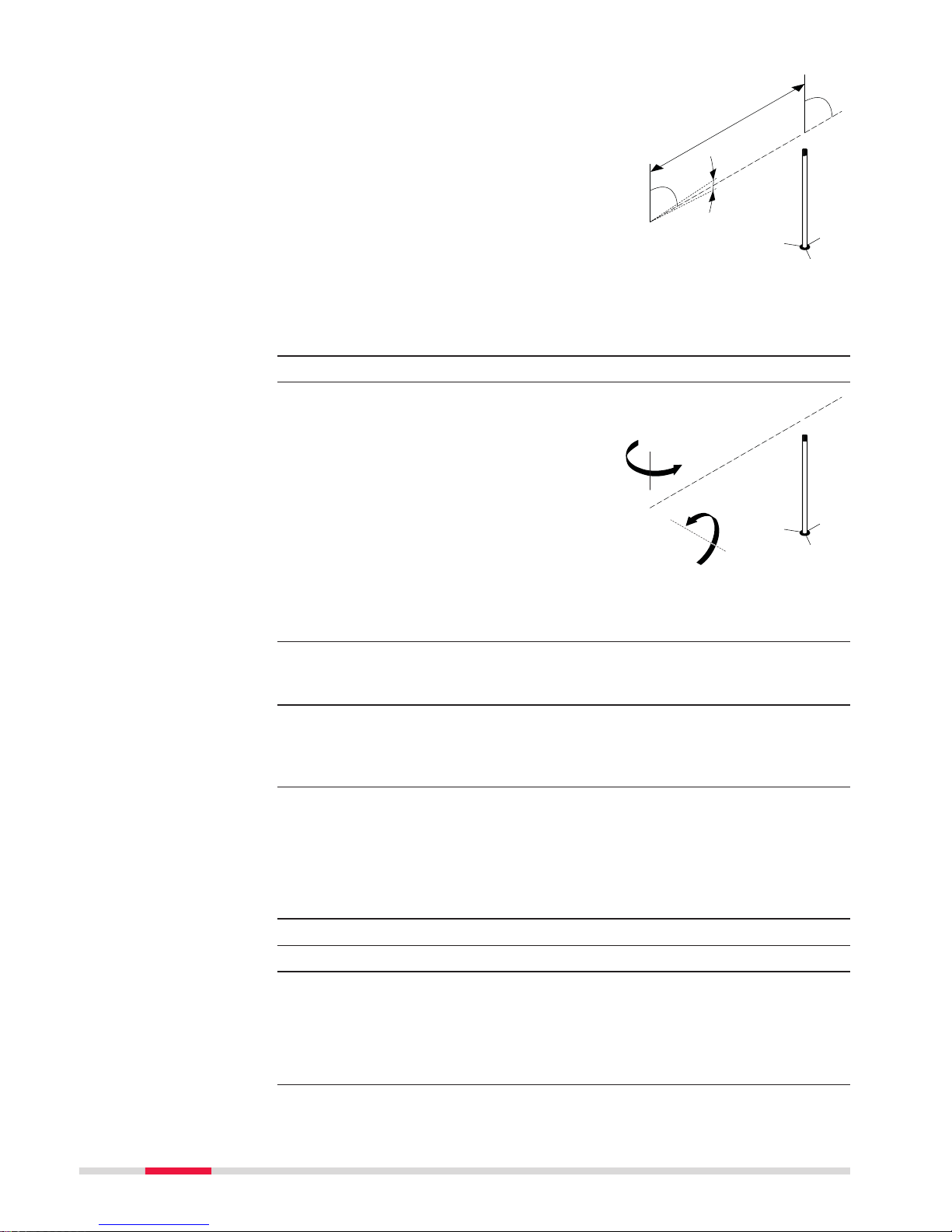
If Calibra
te the automatic tar-
get aiming is checked and an
ATR is available, the adjustment
will include the determination of
the ATR Hz and V adjustment
errors.
☞
Use a clean Leica
standard prism as the
target. Do not use a
360° prism.
0016258_001
± 9°
~ 100 m
5. The procedure can be started in any face.
6. Measure t
o measure and to
continue to the next screen.
Non-motorised instruments
guide to the other face.
☞
The fine pointing has
t
o be performed man-
ually in both faces.
0016259_001
180°
180°
7. Face II measurement
Measure to measure the same target in the other face and to calcu-
late the instrument errors.
☞
If one or more errors are bigger than the predefined limits, the procedure must be repeated. All measurements of the current run are
rejected and none of them is averaged with the results from previous
runs.
8. Adjustment Status
Number of measurements: Shows the number of runs completed.
One run consists of a measurement in face I and face II.
l Component quality (1 σ): and similar lines show the standard
deviations of the determined adjustment errors. The standard deviations can be calculated from the second run onwards.
☞
Measure at least two runs.
9. Next to continue with the check & adjust procedure.
10. Select Add another calibration loop if more runs have to be
added. Next and continue with step 4.
OR
Select Finish the calibration & store the results to finish the cali-
bration process. Next to view the adjustment results.
11. Select Finish to accept the results. No more runs can be added later.
52 Check & Adjust
Page 53
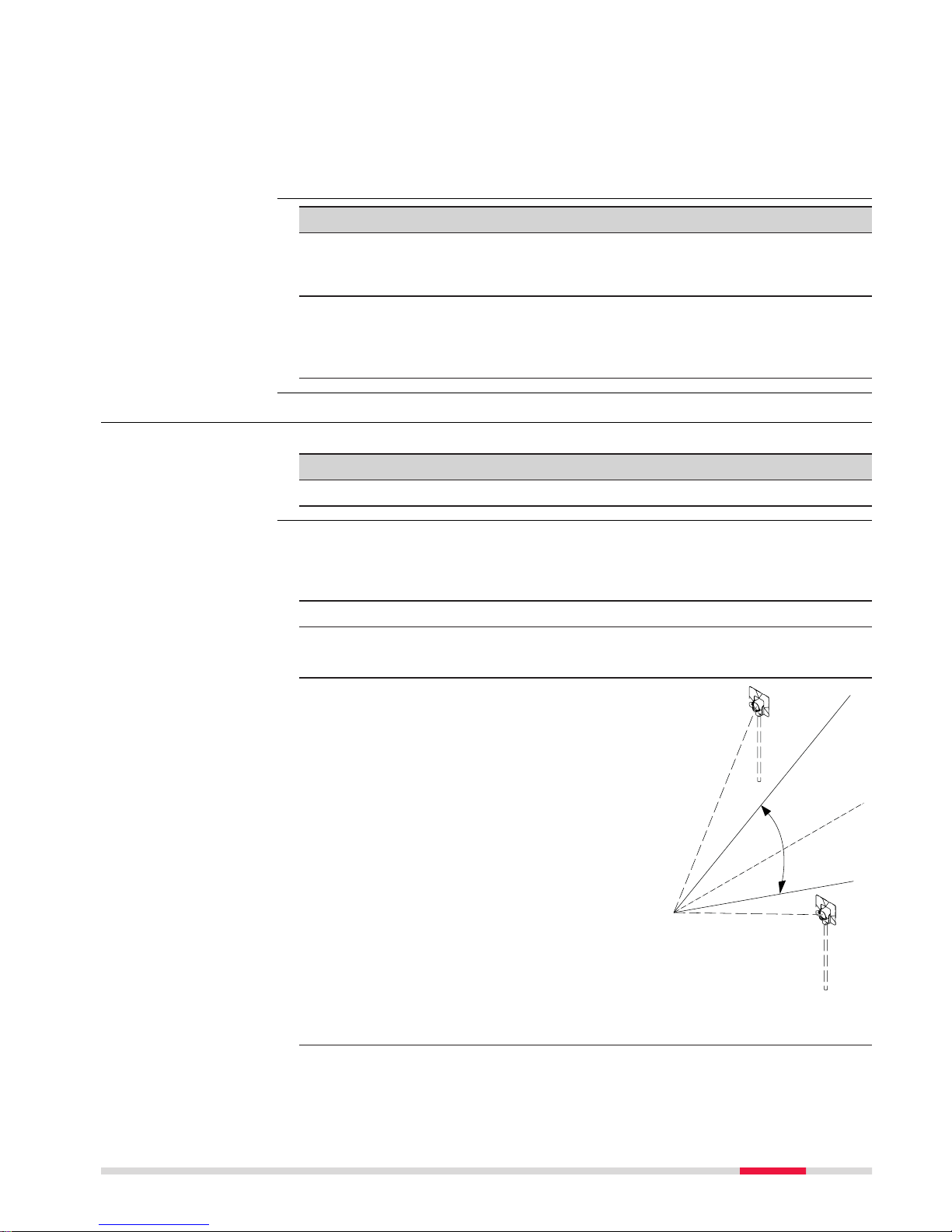
OR
Select R
edo to decline all measurements and to repeat all calibration
runs.
OR
Back returns to the previous screen.
IF the results are THEN
to be stored If the Use status is set to Yes, N
ext over-
writes the old adjustment errors with the
new ones.
to be determined again Redo rejects all new determined adjustment
errors and repeats the whole procedure.
Refer to paragraph "Combined adjustment
procedure step-by-step".
5.4 Tilting Axis Adjustment (a)
This adjustment procedure determines the following instrument error:
Instrument error Description
a Tilting-axis error
The following table explains the most common settings.
☞
Determine the horizontal collimation error (c) before starting this
p
rocedure.
1. Leica Captivate - Home: Settings\TS instrument\Check & adjust
2. Check & Adjust
Select the option: Check & adjust the tilting axis
3. Face I measurement
Aim the telescope accurately at
a target at about 100 m distance (or at least 20 m). The
target must be positioned at
least 27°/30 gon above or
beneath the horizontal plane.
The procedure can be started in
any telescope face.
0016260_001
V=90°
+ 27°
- 27°
Next step
Description
Determination of tilting axis err
or step-by-
step
Check & Adjust 53
Page 54
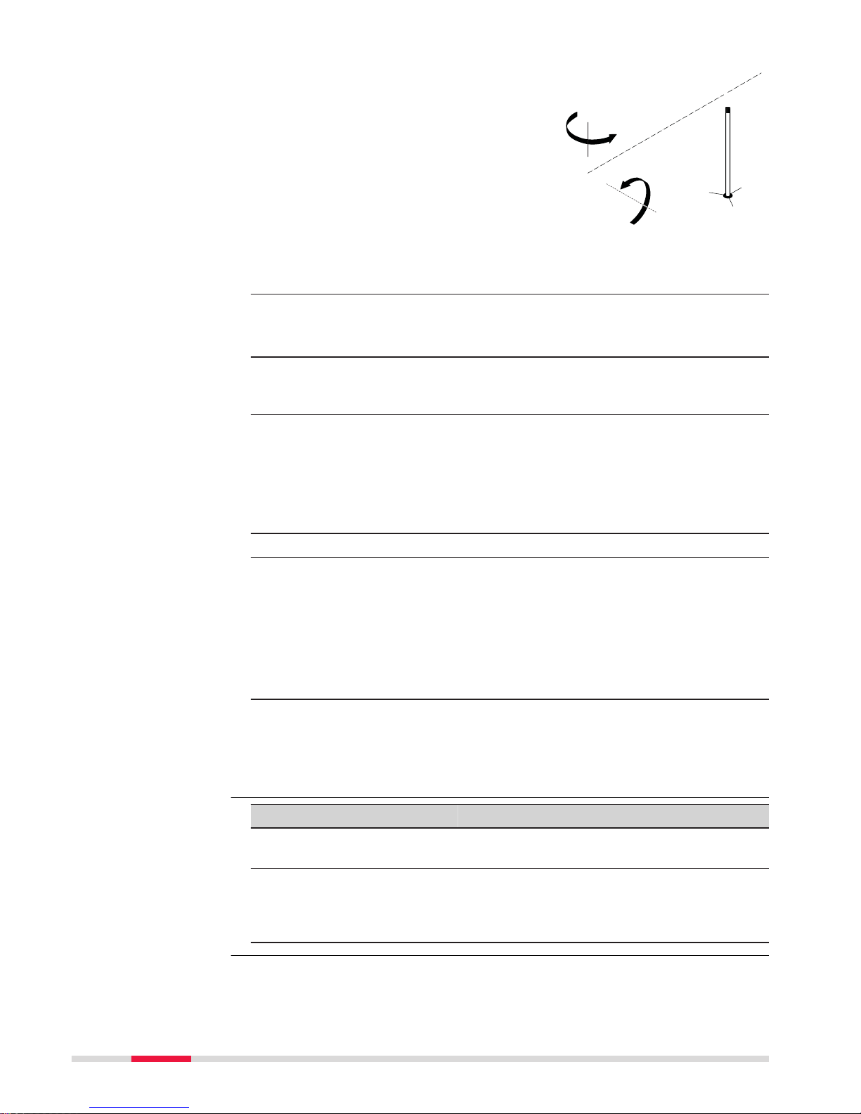
4. Measure t
o measure and to
continue to the next screen.
Motorised instruments change
automatically to the other face.
Non-motorised instruments
guide t
o the other face.
☞
The fine pointing
must be performed
manually in both
faces.
0016259_001
180°
180°
5. Face II measurement
Measure to measure the same target in the other face and to calcu-
late the tilting axis error.
☞
If the error is bigger than the predefined limit, the procedure must
be repeated. The tilting axis measurements of the current run are
then rejected and not averaged with the results from previous runs.
6. Adjustment Status
Number of measurements: Shows the number of runs completed.
One run consists of a measurement in face I and face II.
a T-axis quality (1 σ): shows the standard deviation of the deter-
mined tilting axis error. The standard deviation can be calculated
from the second run onwards.
☞
Measure at least two runs.
7. Next to continue with the check & adjust procedure.
8. Select Add another calibration loop if more runs have to be
added. Next and continue with step 3.
OR
Select Finish the calibration & store the results to finish the cali-
bration process. No more runs can be added later. Next to view the
adjustment results.
9. Select Finish to accept the results. No more runs can be added later.
OR
Select Redo to decline all measurements and to repeat all calibration
runs.
IF the results are THEN
to be stored Next overwrites the old tilting axis error with
the new one.
to be determined again Redo rejects the new determined tilting axis
error and repeats the whole procedure. Refer
to paragraph "Determination of tilting axis
error step-by-step".
Next step
54 Check & Adjust
Page 55
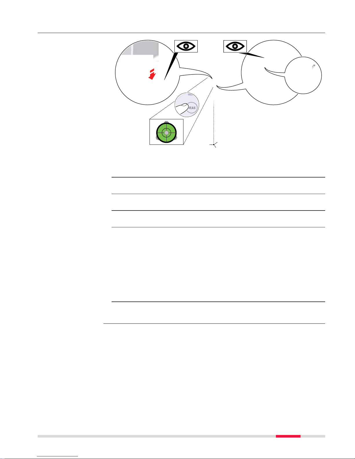
5.5 Adjusting the Circular Level of the Instrument and Tribrach
4
5b
5b
5b
4
5b5b5b
4
0016261_001
2
1
1. Place and secure the instrument into the tribrach and onto a tripod.
2. Using the tribrach footscrews, level the instrument with the electr
onic level.
3. Select Settings\TS instrument\Level & compensator to access
the Level & Compensator panel.
4. Check the position of the circular level on the instrument and tribrach.
5.
a If both circular levels are centred, no adjustments are neces-
sary
b If one or both circular levels are not centred, adjust as follows:
Instrument: If it extends beyond the circle, use the supplied allen
key to centre it with the adjustment screws. Turn the instrument by
200 gon (180°). Repeat the adjustment procedure if the circular
level does not stay centred.
Tribrach: If it extends beyond the circle, use the supplied allen key
to centre it with the adjustment screws.
☞
After the adjustments, all adjusting screws must have the same tightening tension and no adjusting screw should be loose.
Adjusting the circular
level s
tep-by-step
Check & Adjust 55
Page 56
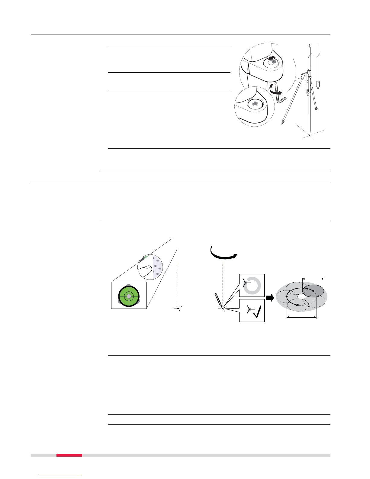
5.6 Adjusting the Circular Level of the Prism Pole
1. Suspend a plumb line.
1
2
4b
4a
TS_080
2. Use a pole bipod, to align the
p
rism pole parallel to the plumb
line.
3. Check the position of the circular
level on the prism pole.
4.
a If the circular level is cen-
tred, no adjustment is necessary.
b If the circular level is not
centred, use an allen key
to centre it with the
adjustment screws.
☞
After the adjustments, all adjusting screws must have the same
tightening tension and no adjusting screw should be loose.
5.7 Inspecting the Laser Plummet of the Instrument
The laser plummet is located in the vertical axis of the instrument. Under normal c
onditions of use, the laser plummet does not need adjusting. If an adjustment is necessary due to external influences, return the instrument to any
Leica Geosystems authorised service workshop.
2
1
360°
3
6
7
5
≤ 3 mm / 1.5 m
Ø 2.5 mm / 1.5 m
008376_001
The following table explains the most common settings.
1. Set up the instrument on the tripod approximately 1.5 m above the
gr
ound and level up.
2. Select Settings\TS instrument\Level & compensator to access
the Level & Compensator panel.
The laser plummet is switched on when the Level & Compensator
panel is entered. Adjust the laser plummet intensity.
☞
Inspection of the laser plummet should be carried out on a
bright, smooth and horizontal surface, such as a sheet of
paper.
3. Mark the centre of the red laser dot on the ground.
Adjusting the circular
level s
tep-by-step
☞
Inspecting the laser
plumm
et step-by-step
56 Check & Adjust
Page 57
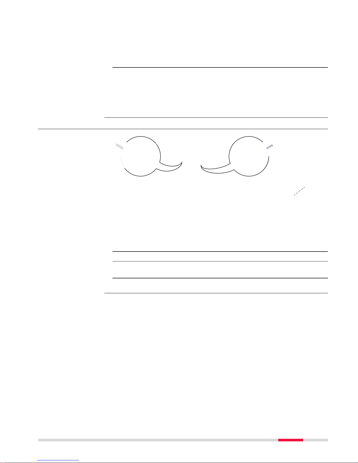
4. Turn the instrument slowly through 360°, carefully observing the
mov
ement of the red laser dot.
☞
The maximum diameter of the circular movement described by the centre of the laser dot should not exceed 3mm
at a height of 1.5m.
5. If the centre of the laser dot describes a perceptible circular movement, or moves more than 3 mm away from the point which was
first marked, an adjustment may be required. Inform your nearest
Leica Geosystems authorised service centre. Depending on brightness and surface, the diameter of the laser dot can vary. At 1.5 m, it
is about 2.5 mm.
5.8 Servicing the Tripod
008706_001
1
2
3
The following table explains the most common settings.
☞
The connections between metal and timber components must
alwa
ys be firm and tight.
1. Tighten the leg cap screws moderately, with the supplied allen key.
2. Tighten the articulated joints on the tripod head enough to keep the
tripod legs open when lifting the tripod off the ground.
3. Tighten the allen screws of the tripod legs.
Servicing the tripod
s
tep-by-step
Check & Adjust 57
Page 58

6 Care and Transport
6.1 Transport
When transporting the equipment in the field, always make sure that you
•
either car
ry the product in its original container,
•
or carry the tripod with its legs splayed across your shoulder, keeping the
attached product upright.
Never carry the product loose in a road vehicle, as it can be affected by shock
and vib
ration. Always carry the product in its container and secure it.
For products for which no container is available use the original packaging or
its equivalent.
When transporting the product by rail, air or sea, always use the complete original Leica G
eosystems packaging, container and cardboard box, or its equiva-
lent, to protect against shock and vibration.
When transporting or shipping batteries, the person responsible for the produc
t must ensure that the applicable national and international rules and regulations are observed. Before transportation or shipping, contact your local passenger or freight transport company.
Exposing the product to high mechanical forces, for example through frequent
tr
ansport or rough handling, or storing the product for a long time may cause
deviations and a decrease in the measurement accuracy. Periodically carry out
test measurements and perform the field adjustments indicated in the User
Manual before using the product.
6.2 Storage
Respect the temperature limits when storing the equipment, particularly in
summer if the equip
ment is inside a vehicle. Refer to "7 Technical Data" for
information about temperature limits.
•
R
efer to "7 Technical Data" for information about storage temperature
range.
•
Remove batteries from the product and the charger before storing.
•
After storage recharge batteries before using.
•
Protect batteries from damp and wetness. Wet or damp batteries must be
dried before storing or use.
•
A storage temperature range of 0 °C to +30 °C / +32 °F to +86 °F in a dry
environment is recommended to minimize self-discharging of the battery.
•
At the recommended storage temperature range, batteries containing a
40% to 50% charge can be stored for up to one year. After this storage
period the batteries must be recharged.
Transport in the field
Transport in a road
vehic
le
Shipping
Shipping, transport of
batteries
Field adjustment
Product
Li-Ion batteries
58 Care and Transport
Page 59
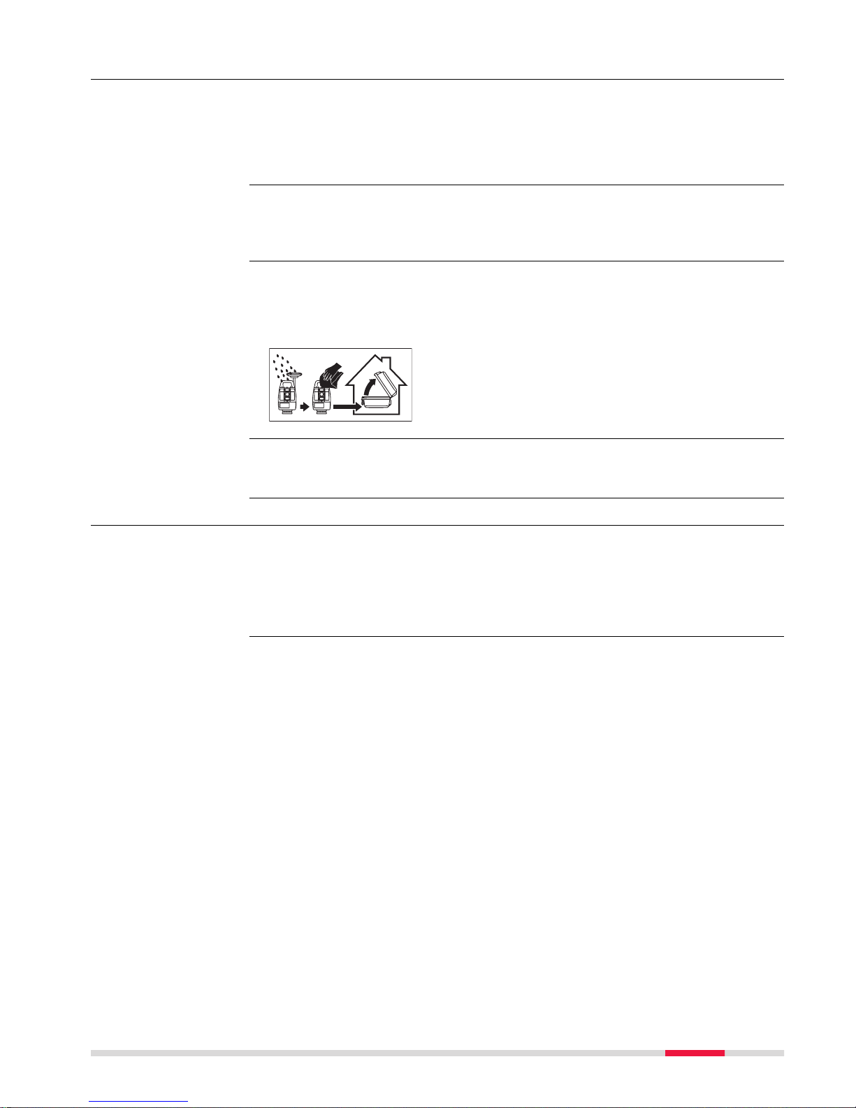
6.3 Cleaning and Drying
•
Blow dus
t off lenses and prisms.
•
Never touch the glass with your fingers.
•
Use only a clean, soft, lint-free cloth for cleaning. If necessary, moisten the
cloth with water or pure alcohol. Do not use other liquids; these may
attack the polymer components.
Prisms that are cooler than the ambient temperature tend to fog. It is not
enoug
h simply to wipe them. Keep them for some time inside your jacket or in
the vehicle to allow them to adjust to the ambient temperature.
Dry the product, the transport container, the foam inserts and the accessories
a
t a temperature not greater than 40°C /104°F and clean them. Remove the
battery cover and dry the battery compartment. Do not repack until everything
is completely dry. Always close the transport container when using in the field.
Keep plugs clean and dry. Blow away any dirt lodged in the plugs of the connec
ting cables.
6.4 Maintenance
An inspection of the motorisation in motorised instruments must be done in a
Leica G
eosystems authorised service centre. Leica Geosystems recommends an
inspection of the product every 12 months.
For instruments which are in intensive or permanent use, for example tunnelling or monitoring, the recommended inspection cycle may be reduced.
Product and accessories
Fogging of prisms
Damp products
Cables and plugs
☞
Care and Transport 59
Page 60

7 Technical Data
7.1 Angle Measurement
Available angular
a
ccuracies
Standard deviation
Hz, V
ISO 17123-3
Display resolution
["] [mgon] ["] [°] [mgon] [mil]
1 0.3 0.1 0.0001 0.1 0.01
2 0.6 0.1 0.0001 0.1 0.01
3 1.0 0.1 0.0001 0.1 0.01
5 1.5 0.1 0.0001 0.1 0.01
Absolute, continuous, diametric.
7.2 Distance Measurement with Reflectors
Reflector Range A Range B Range C
[m] [ft] [m] [ft] [m] [ft]
Standard prism
(G
PR1)
1800 6000 3000 10000 3500 12000
Three standard
prisms
(GPR1)
2300 7500 4500 14700 5400 17700
360° prism
(GRZ4, GRZ122)
800 2600 1500 5000 2000 7000
360° Mini prism
(GRZ101)
450 1500 800 2600 1000 3300
Mini prism
(GMP101)
800 2600 1200 4000 2000 7000
Reflector tape
GZM31)
60 mm x 60 mm
150 500 250 800 250 800
Shortest measuring distance: 1.5 m
Range Description
A Strong haze, visibility 5km; or strong sunlight, severe
he
at shimmer
B Light haze, visibility about 20km; or moderate sun-
light, slight heat shimmer
C Overcast, no haze, visibility about 40km; no heat
shimmer
Measurements can be made to reflector tapes over the entire range without
ex
ternal ancillary optics.
Accuracy
Characteristics
Range
Atmospheric condit
ions
☞
60 Technical Data
Page 61

Accuracy refers to measurements to standard prisms.
Distance
m
easuring
mode
Standard
deviation
ISO 17123-4,
standard prism
Standard
deviation
ISO 17123-4,
tape
Measurement
time, typical [s]
Once 1 mm + 1.5 ppm 3 mm + 2 ppm 2.4
Once & fast 2 mm + 1.5 ppm 3 mm + 2 ppm 2.0
Continuously 3 mm + 1.5 ppm 3 mm + 2 ppm < 0.15
Repeatedly &
average
1 mm + 1.5 ppm 1 mm + 1.5 ppm -
Beam interruptions, severe heat shimmer and moving objects within the beam
pa
th can result in deviations of the specified accuracy.
The display resolution is 0.1 mm.
Type Description
Principle Phase measurement
Type Coaxial, visible red laser
Carrier wave 658 nm
Measuring system System Analyzer Basis 100 MHz - 150 MHz
7.3 Distance Measurement without Reflectors
(N
on-Prism mode)
R500
Kodak Gray Card Range D Range E Range F
[m] [ft] [m] [ft] [m] [ft]
White side, 90 %
r
eflective
250 820 400 1310 >500 >1640
Grey side, 18 %
reflective
150 490 200 660 >200 >660
R1000
Kodak Gray Card Range D Range E Range F
[m] [ft] [m] [ft] [m] [ft]
White side, 90 %
r
eflective
800 2630 1000 3280 >1000 >3280
Grey side, 18 %
reflective
400 1320 500 1640 >500 >1640
Range of Measurement: 1.5 m - 1200 m
Display unambiguous: up to 1200 m
Range Description
D Object in strong sunlight, severe heat shimmer
E Object in shade, or overcast
Accuracy
Characteristics
Range
Atmospheric condit
ions
Technical Data 61
Page 62

Range Description
F Underground, night and twilight
Standard
m
easuring
Standard
deviation
ISO 17123-4
Measure time,
typical [s]
Measure time,
maximum [s]
0 m - 500 m 2 mm + 2 ppm 3 - 6 12
>500 m 4 mm + 2 ppm 3 - 6 12
Object in shade, sky overcast. Beam interruptions, severe heat shimmer and
moving objec
ts within the beam path can result in deviations of the specified
accuracy. The display resolution is 0.1 mm.
Type Description
Type Coaxial, visible red laser
Carrier wave 658 nm
Measuring system System Analyzer Basis 100 MHz - 150 MHz
Distance [m] Laser dot size, approximately [mm]
at 30 7 x 10
at 50 8 x 20
at 100 16 x 25
7.4 Distance Measurement - Long Range (LO mode)
The range of the long range measurements is the same for R500 and R1000.
Reflector Range A Range B Range C
[m] [ft] [m] [ft] [m] [ft]
Standard prism
(G
PR1)
2200 7300 7500 24600 >10000 >33000
Range of measurement: 1000 m to 12000 m
Display unambiguous: up to 12000 m
Range Description
A Strong haze, visibility 5km; or strong sunlight, severe
he
at shimmer
B Light haze, visibility about 20km; or moderate sun-
light, slight heat shimmer
C Overcast, no haze, visibility about 40km; no heat
shimmer
Standard measuring
Standard
devia
tion
ISO 17123-4
Measure time,
typical [s]
Measure time,
maximum [s]
Long Range 5 mm + 2 ppm 2.5 12
Accuracy
Characteristics
Laser dot size
Range
Atmospheric condit
ions
Accuracy
62 Technical Data
Page 63

Beam interruptions, severe heat shimmer and moving objects within the beam
pa
th can result in deviations of the specified accuracy. The display resolution is
0.1 mm.
Type Description
Principle Phase measurement
Type Coaxial, visible red laser
Carrier wave 658nm
Measuring system System Analyzer Basis 100MHz - 150MHz
7.5 Automatic Target Aiming (ATR)
Reflector Range (Target Aiming)
[m] [ft]
Standard prism
(G
PR1)
1000 3300
360° prism
GRZ4, GRZ122)
800 2600
360° Mini prism
(GRZ101)
350 1150
Mini prism
(GMP101)
500 1600
Reflector tape
60 mm x 60 mm
45 150
☞
The maximum range can be restricted by poorer conditions, for
example rain.
Shortest measuring distance: 360° prism (Target aiming): 1.5 m
Shortest measuring distance: 360° prism (Target locking): 5 m
Type Accuracy
ATR angle accuracy Hz, V (std. dev. ISO 17123-3) 1 " (0.3 mgon)
Base Positioning accuracy (std.dev.) ± 1 mm
Type Value
Typical search time in field of view 1.5 s
Field of view 1°25’/1.55 gon
Definable search windows Yes
Type Description
Principle Digital image processing
Type Infrared laser
Characteristics
Range of targe
t aiming/
target locking
ATR accuracy with the
G
PR1 prism
Searching
Characteristics
Technical Data 63
Page 64

7.6 Lock
Reflector Range (Target Locking)
[m] [ft]
Standard prism
(G
PR1)
800 2600
360° prism
GRZ4, GRZ122)
600 2000
360° Mini prism
(GRZ101)
200 660
Mini prism
(GMP101)
400 1300
Reflector tape
60 mm x 60 mm
not qualified
☞
The maximum range can be restricted by poorer conditions, for
example rain.
Shortest measuring distance: 360° prism (Target aiming): 1.5 m
Shortest measuring distance: 360° prism (Target locking): 5 m
Direction of prism movement
Tangential Radial
Prism Lock only 14 m/s at 20 m 25 m/s
Prism Lock with
M
easure distance:
Continuously
6 m/s at 20 m 6 m/s
☞
A tangential movement means the prism is passing by the instrument
a
t the specified distance.
A radial movement means the prism is moving away from or towards
the instrument in the line of sight direction.
7.7 SpeedSearch
Reflector Range
[m] [ft]
Standard prism
(G
PR1)
300 1000
360° prism
(GRZ4, GRZ122)
300* 1000*
360° mini prism
(GRZ101)
Not recommended
Mini prism
(GMP101)
100 330
Measurements at the vertical limits of the fan or under unfavourable atmospher
ic conditions may reduce the maximum range. (*optimally aligned to the
instrument)
Range of target aiming/
target locking
Maximum speed in
lock mode
Range
64 Technical Data
Page 65

Shortest measuring distance: 1.5 m
Type Value
Typical search time 7 s
Default search area Hz: 400 gon, V: 40 gon
Definable search windows
Yes
Type Description
Principle Digital signal processing
Type Infrared laser
7.8 Leica LOC8 Theft Deterrence – Positioning, Tracking and
Lo
cking
Type Band [MHz]
GSM 850 / 900
DCS 1800
PCS 1900
WCDMA 850 / 900 / 1900 / 2100
TI CC2541 BT4.0
7.9 SmartStation
7.9.1 SmartStation Accuracy
Measurement precision and accuracy in position and accuracy in height are
dep
endent upon various factors including the number of satellites tracked,
constellation geometry, observation time, ephemeris accuracy, ionospheric disturbance, multipath and resolved ambiguities. Figures quoted assume normal
to favourable conditions.
Type Position accuracy
Horizontal 5 mm + 0.5 ppm
Vertical 10 mm + 0.5 ppm
When used within reference station networks the position accuracy is in
ac
cordance with the accuracy specifications provided by the reference station
network.
Type Description
Method Leica SmartCheck+ technology
Reliability of initialisation Better than 99.99 %
Time of initialisation Typically 8 s*
Range Up to 50 km*
Searching
Characteristics
Band
Platform Bluetooth
☞
Accuracy
Initialisation
Technical Data 65
Page 66
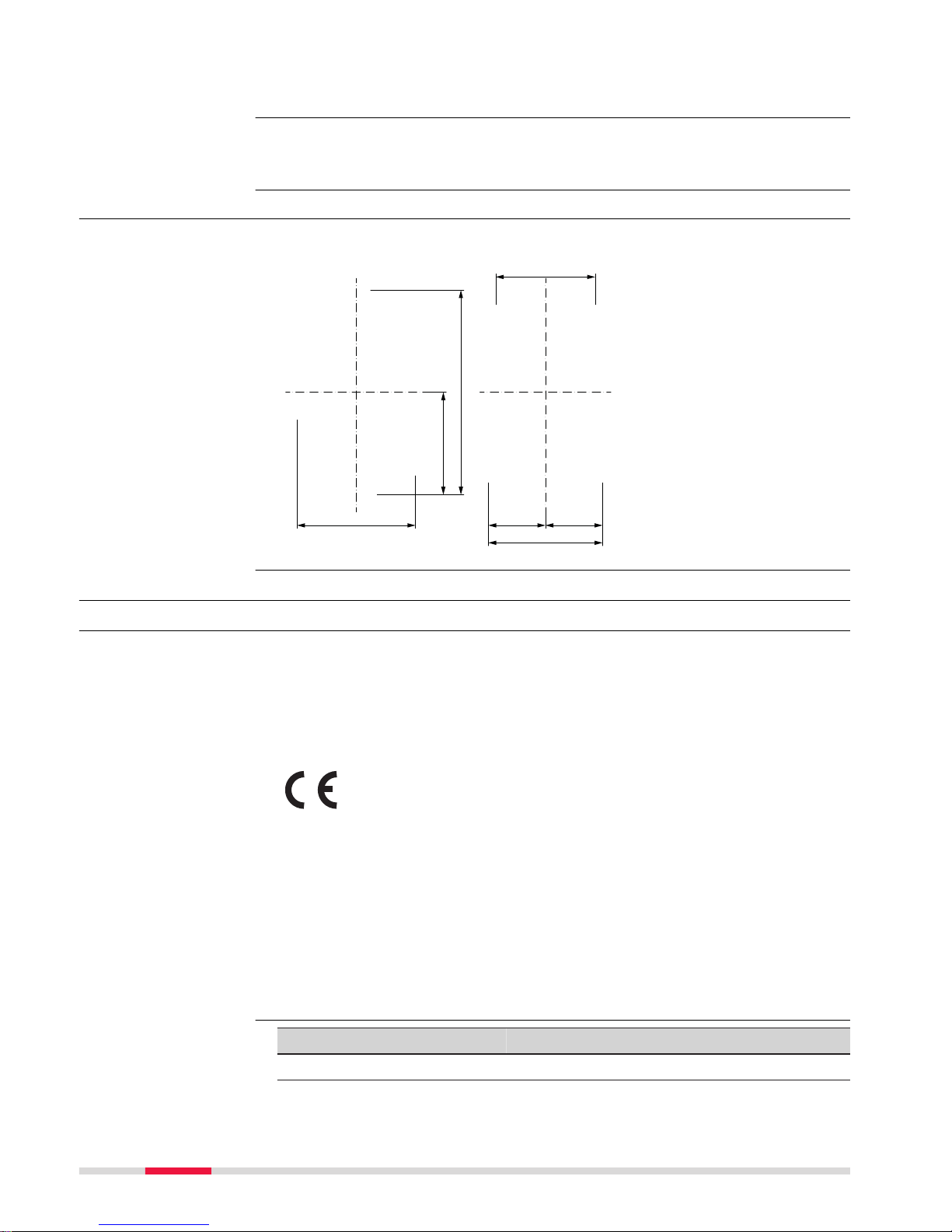
* Might vary due to atmospheric conditions, signal multipath, obstructions, signal geo
metry and number of tracked signals.
Formats for data reception:
Leica, Leica 4G, CM
R, CMR+, RTCM 2.2, 2.3, 3.0, 3.1, 3.2 MSM
7.9.2 SmartStation Dimensions
With GS16
0016834_001
107 mm 107 mm
214 mm
190 m m
226 mm
195.7 mm
392 mm
7.10 Conformity to National Regulations
7.10.1 TS13
•
F
CC Part 15 (applicable in US)
•
Hereby, Leica Geosystems AG declares that the radio equipment type
TS13 is in compliance with Directive 2014/53/EU and other applicable
European Directives.
The full text of the EU declaration of conformity is available at the following Internet address: http://www.leica-geosystems.com/ce.
Class 1 equipment according to European Directive 2014/53/EU
(RED) can b
e placed on the market and be put into service with-
out restrictions in any EEA member state.
•
T
he conformity for countries with other national regulations not covered
by the FCC part 15 or European Directive 2014/53/EU has to be approved
prior to use and operation.
•
Japanese Radio Law and Japanese Telecommunications Business Law
Compliance.
•
This device is granted pursuant to the Japanese Radio Law (
電波法
)
and the Japane
se Telecommunications Business Law (
電気通信事業法
).
•
T
his device should not be modified (otherwise the granted designa-
tion number will become invalid).
Type Frequency Band [MHz]
Bluetooth 2402 - 2480
RTK data formats
SmartStation
dim
ensions
Conformity to
na
tional regulations
Frequency band
66 Technical Data
Page 67

Type Frequency Band [MHz]
WLAN 2400 - 2473, channel 1-11
Type Output Power [mW]
Bluetooth <10
WLAN (802.11b) 50
WLAN (802.11g) 32
Type Bluetooth WLAN
Antenna Integrated antenna Integrated antenna
Gain [dBi] 0 0
Connector - -
Frequency band [MHz] 2400 - 2500 2400 - 2500
7.10.2 RadioHandle
•
F
CC Part 15 (applicable in US)
•
The conformity for countries with other national regulations not covered
by the FCC part 15 or European Directive 2014/53/EU has to be approved
prior to use and operation.
•
Japanese Radio Law and Japanese Telecommunications Business Law
Compliance.
•
This device is granted pursuant to the Japanese Radio Law (
電波法
)
and the Japane
se Telecommunications Business Law (
電気通信事業法
).
•
T
his device should not be modified (otherwise the granted designa-
tion number will become invalid).
•
F
CC Part 15 (applicable in US)
•
The conformity for countries with other national regulations not covered
by the FCC part 15 or European Directive 2014/53/EU has to be approved
prior to use and operation.
•
Japanese Radio Law and Japanese Telecommunications Business Law
Compliance.
•
This device is granted pursuant to the Japanese Radio Law (
電波法
)
and the Japane
se Telecommunications Business Law (
電気通信事業法
).
•
T
his device should not be modified (otherwise the granted designa-
tion number will become invalid).
Type Frequency Band [MHz]
RH16 Limited to 2402 - 2480
RH17 Limited to 2402 - 2480
Value
< 100 mW (e. i. r. p.)
Type l/2 dip
ole antenna
Gain [dBi] 2
Output power
Antenna
Conformity to
na
tional regulations
for RH16
Conformity to
national regulations
for RH17
Frequency band
Output power
Antenna
Technical Data 67
Page 68

Type l/2 dip
ole antenna
Connector Special customized SMB
7.10.3 Dangerous Goods Regulations
Many products of Leica Geosystems are powered by Lithium batteries.
Lithium ba
tteries can be dangerous under certain conditions and can pose a
safety hazard. In certain conditions, Lithium batteries can overheat and ignite.
☞
When carrying or shipping your Leica product with Lithium batteries
onboard a commercial aircraft, you must do so in accordance with the
IATA Dangerous Goods Regulations.
☞
Leica Geosystems has developed Guidelines on “How to carry Leica
products” and “How to ship Leica products” with Lithium batteries.
Before any transportation of a Leica product, we ask you to consult
these guidelines on our web page
(http://www.leica-geosystems.com/dgr) to ensure that you are in
accordance with the IATA Dangerous Goods Regulations and that the
Leica products can be transported correctly.
☞
Damaged or defective batteries are prohibited from being carried or
transported onboard any aircraft. Therefore, ensure that the condition
of any battery is safe for transportation.
7.11 General Technical Data of the Product
Several factors can influence the system's accuracy for determining the location
o
f a prism:
•
Internal ATR accuracy
•
Angular accuracy of the instrument
•
Type and centring accuracy of the prism
•
Selected EDM measuring program
•
External measuring conditions
Therefore, the overall pointing accuracy of the determined point location can
be lower than the given angular accuracy and the ATR accuracy.
The following paragraphs provide a short overview of these influencing factors
and their possible intensities.
Angular accuracy
The accuracy of angular measurements depends on the instrument type. The
angular accuracy for total stations is typically in the range from 0.5² to 5². The
resulting error depends on the measurement distance.
Angular accuracy
Possible deviation* a
t 100 m distance
1² ~0.5 mm
3² ~1.5 mm
*
Orthogonal to the line of sight.
☞
Refer to the data sheet of the respective instrument model for informa
tion about the angular accuracy.
EDM accuracy
T
he distance measurement accuracy consists of two parts: a fixed value and a
distance-dependent value (ppm-value).
Dangerous Goods
R
egulations
System Accuracy
68 Technical Data
Page 69

Example: "Single measurements: 1 mm + 1.5 ppm"
T
he EDM accuracies for prism and reflectorless measurements can differ. Addi-
tionally, the accuracies can differ depending on the used technologies.
☞
Refer to the appropriate data sheet for information about the EDM
accuracy.
ATR accuracy
Automatic target aiming accuracies, like those of the ATR, are in general the
same as the stated angular accuracy. Therefore these accuracies are also distance-dependent parameters.
External impacts, like heat shimmer, rain (prism surface covered by rain drops),
fog, dust, strong background lights, dirty targets, alignment of the targets etc.
can have a significant influence on the automated target. In addition the selected EDM mode affects the ATR performance. Under good environmental conditions and with a clean, properly aligned target the accuracy of the automated
target aiming is equivalent to the manual target aiming (presumed valid calibration values).
Type and centring accuracy of the prism
The prism centring accuracy depends mainly on the used prism type, for example:
Prism type Centring accuracy
Leica GPR1 Circular prism 1.0 mm
Leica GPH1P Precision circular prism 0.3 mm
Leica GRZ122 360° prism 2.0 mm
Leica GRZ4 360° prism 5.0 mm
☞
Refer to the white paper "Leica Surveying Reflectors" for information
ab
out the different centring accuracies.
Additional influencing factors
When determining absolute coordinates, the following parameters can also
a
ffect the resulting accuracy:
•
Environmental conditions: temperature, air pressure and humidity
•
Typical instrument errors, such as horizontal collimation error or index
error.
•
Proper functioning of laser plummet or optical plummet
•
Correct horizontal levelling
•
Setup of the target
•
Quality of additional equipment, such as tribrach or tripod.
Type Value
Magnification 30x
Free Objective aperture 40mm
Focusing 1.7m/5.6ft to infinity
Field of view 1°30’/1.66gon
2.7m a
t 100m
Telescope
Technical Data 69
Page 70

Angular accuracy
ins
trument ["]
Setting accuracy Setting range
["] [mgon] [’] [gon]
1 0.5 0.2 4 0.07
2 0.5 0.2 4 0.07
3 1.0 0.3 4 0.07
5 1.5 0.5 4 0.07
Type Value
Circular level sensitivity 6’/2mm
Electronic level resolution 2"
Type Description
Keyboard 4 keys, 4 LEDs
Position Face I only
Type Description
Display 5" (inch), WVGA (800*480), colour, touch
Keyboard 25 keys, illumination
Angle display 360°’", 360° decimal, 400 gon, 6400 mil, V %
Distance display m, ft int, ft us, ft int inch, ft us inch
Position For both faces optional
Touch screen Screen protection foil on glass
Name Description
Cable
•
5 pin LE
MO-0 for power, communication,
data transfer.
•
This port is located at the base of the
instrument.
RadioHandle
•
Hotshoe connection for RadioHandle
•
This port is located on top of Communication side cover.
☞
For this functionality, the TS13
R
obotic licence must be purchased.
Bluetooth
•
Blue
tooth module for communication.
•
This port is housed within Communication side cover.
USB host port
•
USB memory stick port for data transfer.
USB device port
•
Cable connections from USB devices for
communication and data transfer.
WLAN
•
WLAN module for Internet access and
communication.
•
This port is housed within the Communication side cover.
Compensator
Level
Four button keyboard
unit
Keyboard display unit
Instrument ports
70 Technical Data
Page 71
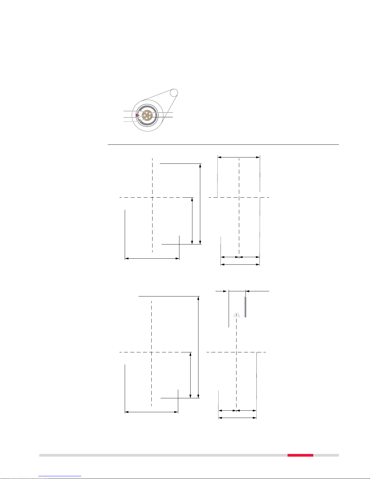
0016263_001
a
b
e
d
c
a Pin 1: Power input
b
Pin 2: not used
c Pin 3: Single ground
d Pin 4: RxD (RS232, receive
data, In)
e Pin 5: TxD (RS232, transmit
data, Out)
0016264_001
164 mm
76mm 88mm
177 mm
226 mm
195.7 mm
336 mm
With RH16/RH17
0016271_001
72 mm
164 mm
76m m 88mm
226 mm
195.7 mm
433.5 mm
Pin assignments of
th
e 5 pin LEMO-0 port
Instrument
dim
ensions
Technical Data 71
Page 72
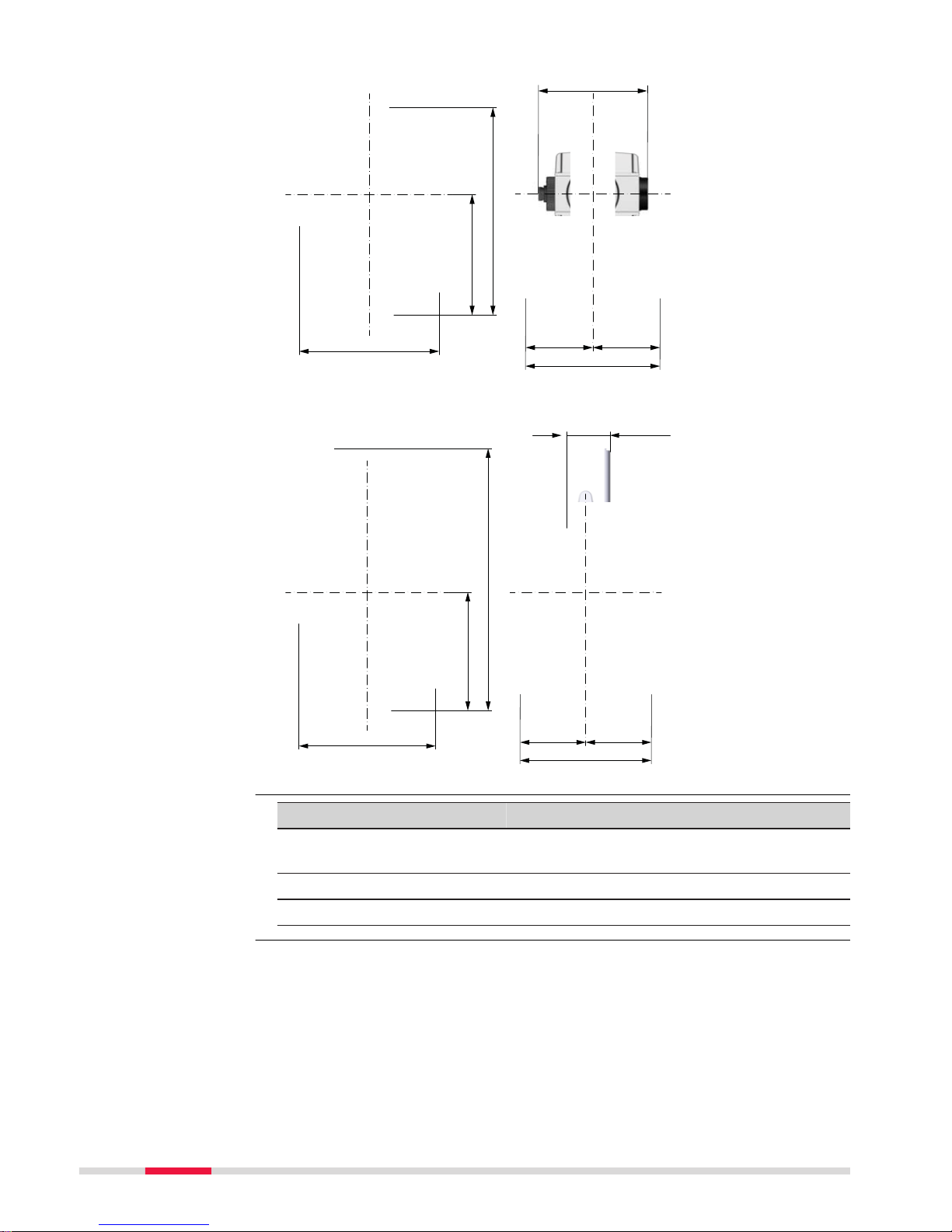
0016835_001
226 mm
195.7 mm
336 mm
107mm 107mm
177 mm
214 mm
With RH16/RH17
0016836_001
72 mm
107mm 107mm
214 mm
226 mm
195.7 mm
433.5 mm
Type Value
Instrument With Four Button Keyboard Unit: 5.0 kg
With K
eyboard Display Unit: 5.3 kg
Tribrach 0.8 kg
Internal battery 0.2 kg
TS13 with the four button keyboard and without display
Us
es the memories only for firmware/license key upload. Data are recorded on
the field controller.
TS13 with the full keyboard and with display
Da
ta can be recorded onto a TS card or into the internal memory.
Weight
Recording
72 Technical Data
Page 73

Type Capacity [MB] Number of measurements
p
er MB
SD card
•
1024
•
8192
1750
Internal
memory
•
2048 1750
Type Value
Type Visible red laser class 2
Location In standing axis of instrument
Accuracy Deviation from plumb line:1.5mm (2 sigma)
a
t 1.5m instrument height
Diameter of laser point 2.5mm at 1.5m instrument height
Description
Endless horizontal and vertical drives
Type Description
Maximum rotating speed 50 gon/s
Type Description
External supply voltage Nominal voltage 12.8 V DC, Range
11.5 V-13.5 V
Type Battery Voltage Capacity
GEB222 Li-Ion 7.4 V 6.0 Ah
Type Battery Voltage Capacity
GEB371 Li-Ion 13 V 16.8 Ah
Temperature
Type Operating temperature
[°C]
Storage temperature
[°C]
All instruments -20 to +50 -40 to +70
Leica SD cards -40 to +80 -40 to +80
Battery internal -20 to +55 -40 to +70
Protection against water, dust and sand
Type Protection
All instruments IP55 (IEC 60529)
Laser plummet
Drives
Motorisation
Power
Internal battery
External battery
Environmental
sp
ecifications
Technical Data 73
Page 74

Humidity
Type Protection
All instruments Max 95 % non condensing
T
he effects of condensation are to be effectively
counteracted by periodically drying out the instrument.
Type Additive
Cons
tant [mm]
ATR SpeedSearch
Standard prism,
GPR1
0.0 yes yes
Mini prism,
GMP101
+17.5 yes yes
360° prism,
GRZ4 / GRZ122
+23.1 yes yes
360° Mini prism,
GRZ101
+30.0 yes not
recommended
Reflector tape
S, M, L
+34.4 yes no
Reflectorless +34.4 no no
There are no special prisms required for ATR or for SpeedSearch.
Type Description
Working range 5 m to 150 m (15 ft to 500 ft)
Position accuracy 5 cm at 100 m (1.97" at 330 ft)
The following automatic corrections are made:
•
Line o
f sight error
•
Tilting axis error
•
Earth curvature
•
Circle eccentricity
•
Compensator index error
•
Vertical index error
•
Standing axis tilt
•
Refraction
•
ATR zero point error
7.12 Scale Correction
By entering a scale correction, reductions proportional to distance can be taken
in
to account.
•
Atmospheric correction.
•
Reduction to mean sea level.
•
Projection distortion.
The slope distance displayed is correct if the scale correction in ppm, mm/km,
which has b
een entered corresponds to the atmospheric conditions prevailing
at the time of the measurement.
Reflectors
Electronic Guide Light
E
GL
Automatic corrections
Use of scale correct
ion
Atmospheric correct
ion DD1
74 Technical Data
Page 75
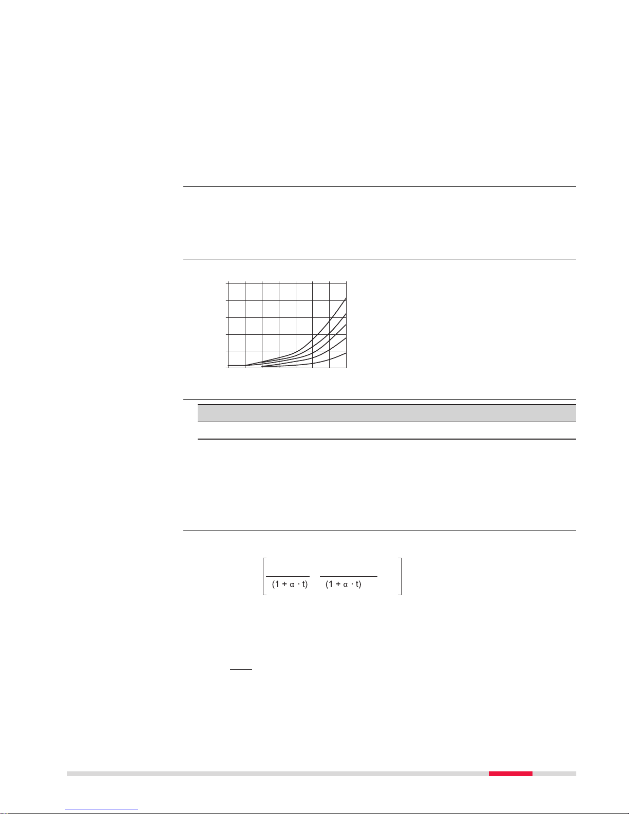
The atmospheric correction includes:
•
Adjus
tments for air pressure
•
Air temperature
•
Relative humidity
For highest precision distance measurements, the atmospheric correction
should b
e determined with an accuracy of 1 ppm. The following parameters
must be redetermined:
•
A
ir temperature to 1 °C
•
Air pressure to 3 mbar
•
Relative humidity to 20 %
The air humidity influences the distance measurement if the climate is
ex
tremely hot and damp.
For high precision measurements, the relative humidity must be measured and
entered along with the air pressure and the temperature.
ppm
+5
+1
+2
+3
+4
+0
-10-20 0 10 20 30 40 50 °C
100%
80%
60%
40%
20%
TS_104
ppmA
ir humidity correction
[mm/km]
% Relative humidity [%]
C° Air temperature [°C]
Type Index n Carrier wave [nm]
Combined EDM 1.0002863 658
The index n is calculated from the formula of the IAG Resolutions (1999), and
is valid f
or:
Air pressure p: 1013.25 mbar
Air temperature t: 12 °C
Relative air humidity h: 60 %
Formula for visible red laser
· 10
x
4.126 · 10-4 · h
-
0.29535 · p
ΔD1= 286.338 -
002419_002
DD1A
tmospheric correction [ppm]
p Air pressure [mbar]
t Air temperature [°C]
h Relative humidity [%]
a
1
273.15
x (7.5 * t/(237.3 + t)) + 0.7857
Air humidity
Air humidity
co
rrection
Index n
Formulas
Technical Data 75
Page 76
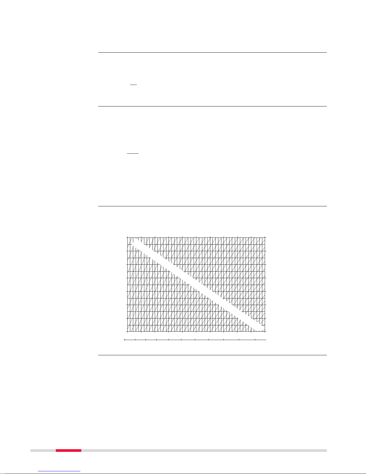
If the basic value of 60 % relative humidity as used by the EDM is retained, the
maximum p
ossible error in the calculated atmospheric correction is 2 ppm,
2 mm/km.
The values for DD2 ar
e always negative and are derived from the following for-
mula:
TS_106
ΔD2= -
H
R
· 10
6
DD2R
eduction to mean sea level [ppm]
H Height of EDM above sea level [m]
R
6.378 * 106 m
The magnitude of the projection distortion is in accordance with the projection
system used in a particular country, for which official tables are generally available. The following formula is valid for cylindrical projections such as that of
Gauss-Krüger:
T
S_107
ΔD3=
X
2
2R
2
· 10
6
DD3Projection distortion [ppm]
X Easting, distance from projection
zero line with the scale factor 1
[km]
R
6.378 * 106 m
In countries where the scale factor is not unity, this formula cannot be directly
ap
plied.
Atmospheric corrections in ppm with temperature [°C], air pressure [mb] and
heig
ht [m] at 60% relative humidity.
TS_108
-40
-35
-30
-25
-20
-15
-10
-5
0
5
10
15
20
25
30
35
40
45
50
55
60
65
70
75
80
85
90
95
100
105
110
115
120
125
130
135
140
50°C50°C
40°C40°C
30°C30°C
20°C20°C
10°C10°C
0°C 0°C
-10°C-10°C
-20°C-20°C
550 mb
5000 m 4500
600 650 700 750 800 850 900 950 1000 1050 mb
550 mb 600 650 700 750 800 850 900 950 1000 1050 mb
4000 3500 3000 2500 2000 1500 1000 500 0 m
Reduction to mean
sea level DD
2
Projection distortion
DD
3
Atmospheric
co
rrections °C
76 Technical Data
Page 77
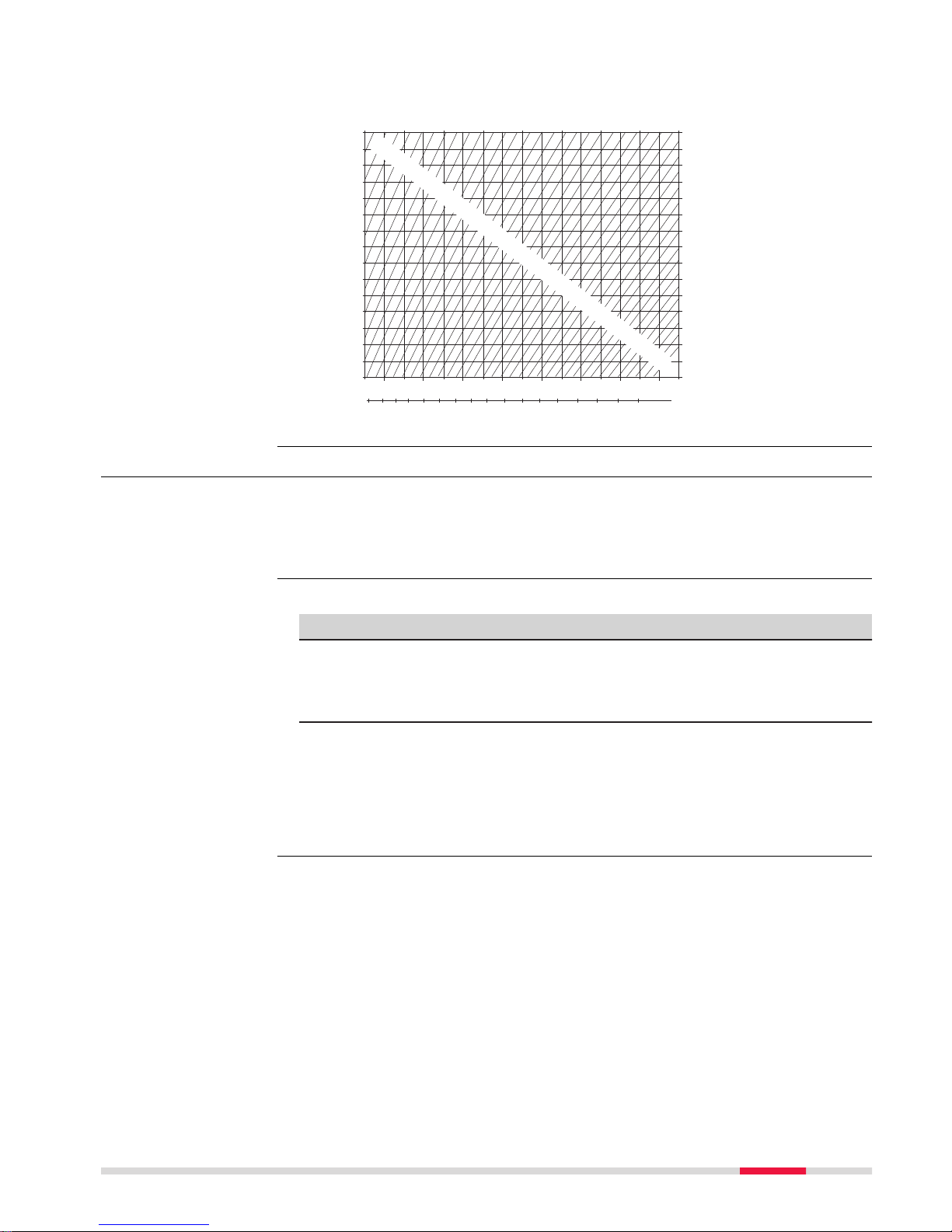
Atmospheric corrections in ppm with temperature [°F], air pressure [inch Hg]
and heig
ht [ft] at 60% relative humidity.
TS_109
130°F
120°F
110°F
100°F
90°F
80°F
70°F
60°F
50°F
40°F
30°F
20°F
10°F
0°F
-10°F
-20°F
130°F
120°F
110°F
100°F
90°F
80°F
70°F
60°F
50°F
40°F
30°F
20°F
10°F
0°F
-10°F
-20°F
16
[ ft ]
17 18 19 20 21 22 23 24 25 26 27 28 29 30 31 32 inch Hg
16 17 18 19 20 21 22 23 24 25 26 27 28 29 30 31 32 inch Hg
16000
15000
14000
13000
12000
11000
10000
9000
8000
7000
6000
5000
4000
3000
2000
1000
o ft
-15
-20
-25
-30
-35
-40
-45
-50
-55
-10
-5
0
5
10
15
20
25
30
35
40
45
50
55
60
65
70
75
80
85
90
95
100
105
110
115
120
125
130
135
140
145
7.13 Reduction Formulas
The reduction formulas are valid for measurements to all reflector types:
•
T
o prisms
•
To reflector tape
•
Reflectorless measurements
Available formats depend on the instrument.
Format Description
•
Ins
trument display
•
DBX
•
ASCII
•
GSI
•
Corrections for the atmospheric
ppm are applied to the slope distances according to the formulas.
•
XML export
•
Output without corrections for
the atmospheric ppm
•
ppm is stored as metadata
•
Corrections are applied during
later input, for example to Infinity
Atmospheric
co
rrections °F
Reflector types
Slope distance co
rrections
Technical Data 77
Page 78
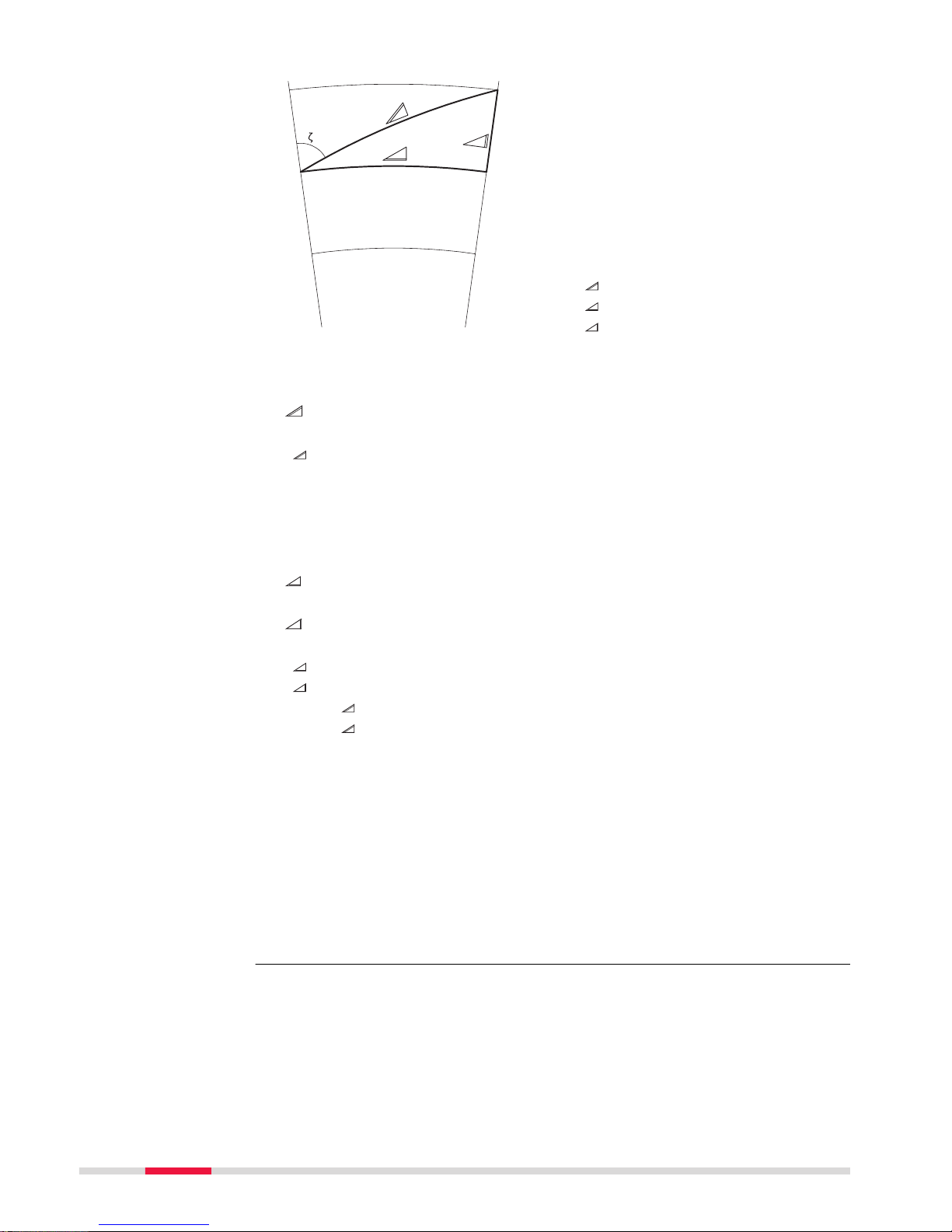
c
a
b
TS_110
a Mean Sea Level
b
Instrument
c Reflector
Slope distance
Horizontal distance
Height difference
The instrument calculates the slope distance, horizontal distance, height differenc
e in accordance with the following formulas:
002425_002
= D0 · ( 1 + ppm · 10
-6
) + AC
Displayed slope distance [m]
D
0
Unc
orrected distance [m]
ppm Atmospheric scale correction [mm/km]
AC Additive constant of the reflector [m]
TS_112
= Y - A · X ·
Y
TS_113
= X + B · Y
2
Horizontal distance [m]
Height difference [m]
Y * |sinz|
X * cosz
z
V
ertical circle reading
A
(1 - k / 2) / R = 1.47 * 10-7 [m-1]
B
(1 - k) / (2 * R) = 6.83 * 10-8 [m-1]
k 0.13 (mean refraction coefficient)
R
6.378 * 106 m (radius of the earth)
Earth curvature (1/R) and mean refraction coefficient (k) are automatically
tak
en into account when calculating the horizontal distance and height difference. The calculated horizontal distance relates to the station height and not
to the reflector height.
In the distance measuring program Averaging, the following values are displayed:
D Slope distance as arithmetic mean of all measurements
s
Standard deviation of a single measurement
n Number of measurements
Formulas
Distance measuring
pr
ogram Averaging
78 Technical Data
Page 79

These values are calculated as follows:
T
S_114
· ∑ D
i
D =
1
n
n
i = 1
Slope distance as arithmetic mean of all measurements
å
Sum
D
i
Sing
le slope distance measurement
n Number of measurements
TS_115
s =
(Di- D)
2
n - 1
=
D
i
2
n - 1
( D
i
)
2
∑
n
i = 1
∑
n
i = 1
∑
n
i = 1
1
n
s Standard deviation of a single slope distance measurement
å
Sum
Slope distance as arithmetic mean of all measurements
D
i
Single slope distance measurement
n Number of distance measurements
The standard deviation of the arithmetic mean of the distance can be calcula
ted as follows:
TS_116
SD =
n
s
Standard deviation of the arithmetic mean of the distance
s
Standard deviation of a single measurement
n Number of measurements
Technical Data 79
Page 80

8 Software Licence Agreement
This product contains software that is preinstalled on the product, or that is
sup
plied to you on a data carrier medium, or that can be downloaded by you
online according to prior authorisation from Leica Geosystems. Such software is
protected by copyright and other laws and its use is defined and regulated by
the Leica Geosystems Software Licence Agreement, which covers aspects such
as, but not limited to, Scope of the Licence, Warranty, Intellectual Property
Rights, Limitation of Liability, Exclusion of other Assurances, Governing Law
and Place of Jurisdiction. Please make sure, that at any time you fully comply
with the terms and conditions of the Leica Geosystems Software Licence
Agreement.
Such agreement is provided together with all products and can also be referred
to and downloaded at the Leica Geosystems home page at
http://leica-geosystems.com/about-us/compliance-standards/legal-documents
or collected from your Leica Geosystems distributor.
You must not install or use the software unless you have read and accepted
the terms and conditions of the Leica Geosystems Software Licence Agreement. Installation or use of the software or any part thereof, is deemed to be
an acceptance of all the terms and conditions of such Licence Agreement. If
you do not agree to all or some of the terms of such Licence Agreement, you
must not download, install or use the software and you must return the
unused software together with its accompanying documentation and the purchase receipt to the distributor from whom you purchased the product within
ten (10) days of purchase to obtain a full refund of the purchase price.
The software on the product may contain copyright-protected software that is
lic
enced under various open source licences.
Copies of the corresponding licences
•
are provided together with the product (for example in the About panel of
the software)
•
can be downloaded on
http://opensource.leica-geosystems.com
If foreseen in the corresponding open source licence, you may obtain the corresponding source code and other related data on
http://opensource.leica-geosystems.com.
Contact
[email protected] in case you need additional information.
Software Licence
Agr
eement
Open Source
information
80 Software Licence Agreement
Page 81

Page 82

Leica Geosystems AG
Heinrich-Wild-Strasse
CH-9435 Heerbrugg
Switzerland
Phone +41 71 727 31 31
www.leica-geosystems.com
870667-1.0.0en
Or
iginal text (870667-1.0.0en)
Published in Switzerland
© 2018 Leica Geosystems AG, Heerbrugg, Switzerland
 Loading...