

Page 1

Leica LS10/LS15
User Manual
Version 3.0
English
Page 2
Introduction
Purchase Congratulations on the purchase of a Leica LS10/LS15 Digital Level.
Product
identification
Trademarks • Windows is a registered trademark of Microsoft Corporation in the United States
Validity of this
manual
Available
documentation
The model and serial number of your product are indicated on the type plate.
Always refer to this information when you need to contact your agency or Leica
Geosystems authorised service workshop.
This manual contains important safety directions as well as instructions for setting up
the product and operating it. Refer to "1 Safety Directions" for further information.
Read carefully through the User Manual before you switch on the product.
Keep for future reference!
and other countries
•
Bluetooth
All other trademarks are the property of their respective owners.
This manual applies to the LS10/LS15 Digital Levels. Where there are differences
between the instruments they are clearly described.
Name Description/Format
LS10/LS15
Quick Guide
LS10/LS15
User Manual
®
is a registered trademark of Bluetooth SIG, Inc.
Provides an overview of the product together with technical data and safety directions. Intended as a quick
reference guide.
All instructions required in order to operate the product
to a basic level are contained in the User Manual.
Provides an overview of the product together with technical data and safety directions.
-
Leica Geosystems
Address Book
Refer to the following resources for all LS10/LS15 documentation/software:
• the Digital Levels USB documentation card
• https://myworld.leica-geosystems.com
On the last page of this manual, you can find the address of Leica Geosystems headquarters. For a list of regional contacts, please visit
http://leica-geosystems.com/contact-us/sales_support.
LS10/LS15, Introduction
2
Page 3
myWorld@Leica Geosystems (https://myworld.leica-geosystems.com) offers a
wide range of services, information and training material.
With direct access to myWorld, you are able to access all relevant services whenever
it is convenient for you.
Service Description
myProducts Add all products that you and your company own and explore your
world of Leica Geosystems: View detailed information on your products and update your products with the latest software and keep upto-date with the latest documentation.
myService View the current service status and full service history of your prod-
ucts in Leica Geosystems service centres. Access detailed information on the services performed and download your latest calibration
certificates and service reports.
mySupport View the current service status and full service history of your prod-
ucts in Leica Geosystems service centres. Access detailed information on the services performed and download your latest calibration
certificates and service reports.
myTraining Enhance your product knowledge with Leica Geosystems Campus -
Information, Knowledge, Training. Study the latest online training
material on your products and register for seminars or courses in
your country.
myTrustedServices
Add your subscriptions and manage users for Leica Geosystems
Trusted Services, the secure software services, that assist you to
optimise your workflow and increase your efficiency.
LS10/LS15, Introduction
3
Page 4

Table of Contents
In this manual Chapter Page
1Safety Directions
1.1 General 7
1.2 Definition of Use 8
1.3 Limits of Use 8
1.4 Responsibilities 8
1.5 Hazards of Use 9
1.6 Electromagnetic Compatibility EMC 11
1.7 FCC Statement, Applicable in U.S. 12
2 Description of the System
2.1 System Components 13
2.2 Container Contents 14
2.3 Instrument Components 15
3User Interface
3.1 Keyboard 16
3.2 Operating Principles 17
3.3 Screen 18
3.4 Status Icons 19
3.5 Softkeys 21
4Operation
4.1 Power Supply 22
4.1.1 Working with the Battery 22
4.2 Data Storage 23
4.3 Instrument Setup 23
4.4 Startup 25
4.5 Main Menu 27
7
13
16
22
5 Measurement Guidelines
5.1 General Measurement Guidelines 28
5.2 Guidelines for Special Measurement Situations 29
5.3 Guidelines for Taking a Measurement 30
5.4 Manual Input Screen for Optical Height Reading 33
6 Settings
6.1 Work Settings 34
6.2 Regional Settings 35
6.3 Data Settings 37
6.4 Screen & Audio Settings 38
6.5 Mode Settings 39
6.6 Interface Settings 41
28
34
LS10/LS15, Table of Contents
4
Page 5

7Programs
7.1 General 43
7.1.1 Common Fields 43
7.1.2 Pointsearch 44
7.1.3 Point ID & Incrementation 45
7.2 Q-Level Program 46
7.2.1 General 46
7.2.2 Measurement Procedure for Q-Level 47
7.3 BasicLevel Program 52
7.4 LineLevel Program 53
7.4.1 General 53
7.4.2 Setting a Job 54
7.4.3 Setting Tolerances 55
7.4.4 Setting a Line and a Method 57
7.4.5 Measurement Procedure for LineLevel 58
7.5 LineAdjust Program 62
7.5.1 General 62
7.5.2 Line Adjustment Step-by-Step 62
43
8Favourites
9Coding
10 Free Coding
11 MapView
11.1 Overview 70
11.2 MapView Components 70
11.2.1 Screen Area 70
12 Tools
12.1 Adjust 72
12.2 System Information 73
12.3 Licence Keys 74
12.4 Instrument Protection with PIN 75
12.5 Loading Software 76
12.6 Compass 77
13 Data Management
13.1 Manage 78
13.2 Exporting Data 79
13.3 Importing Data 81
13.4 Working with a USB Memory Stick 83
13.5 Working with Bluetooth 85
13.6 Working with Leica Infinity 85
65
66
68
70
72
78
14 Check & Adjust
14.1 Overview 86
14.2 Preparation 86
14.3 Adjusting Line-of-Sight Error 87
14.4 Adjusting the Optical Crosshair 90
14.5 Aligning the Camera Crosshair 91
14.6 Calibrating the Digital Compass 92
14.7 Adjusting the Circular Level of the Instrument 93
14.8 Adjusting the Electronic Level 93
14.9 Servicing the Tripod 94
LS10/LS15, Table of Contents
86
5
Page 6

15 mySecurity
95
16 Care and Transport
16.1 Care 97
16.2 Transport 97
16.3 Storage 97
16.4 Cleaning and Drying 98
17 Technical Data
17.1 General Technical Data of the Instrument 99
17.2 Measurements 101
17.3 Conformity to National Regulations 102
17.3.1 General 102
17.3.2 Dangerous Goods Regulations 102
18 Software Licence Agreement
Appendix A Menu Tree
Appendix B Directory Structure
Appendix C Corrections and Formulas
Appendix D GeoCom Commands
Appendix E GSI Online Commands
E.1 Introduction 110
E.2 General Commands and Descriptions 110
E.3 Operating Commands 111
97
99
103
104
106
107
108
110
LS10/LS15, Table of Contents
6
Page 7
1Safety Directions
1.1 General
Description The following directions enable the person responsible for the product, and the
person who actually uses the equipment, to anticipate and avoid operational hazards.
The person responsible for the product must ensure that all users understand these
directions and adhere to them.
About Warning
Messages
Warning messages are an essential part of the safety concept of the instrument. They
appear wherever hazards or hazardous situations can occur.
Warning messages...
• make the user alert about direct and indirect hazards concerning the use of the
product.
• contain general rules of behaviour.
For the users‘ safety, all safety instructions and safety messages shall be strictly
observed and followed! Therefore, the manual must always be available to all persons
performing any tasks described here.
DANGER, WARNING, CAUTION and NOTICE are standardised signal words for identifying levels of hazards and risks related to personal injury and property damage. For
your safety, it is important to read and fully understand the following table with the
different signal words and their definitions! Supplementary safety information
symbols may be placed within a warning message as well as supplementary text.
Type Description
DANGER
WARNING
Indicates an imminently hazardous situation which, if not
avoided, will result in death or serious injury.
Indicates a potentially hazardous situation or an unintended
use which, if not avoided, could result in death or serious injury.
NOTICE
LS10/LS15, Safety Directions
CAUTION
Indicates a potentially hazardous situation or an unintended
use which, if not avoided, may result in minor or moderate
injury.
Indicates a potentially hazardous situation or an unintended
use which, if not avoided, may result in appreciable material,
financial and environmental damage.
Important paragraphs which must be adhered to in practice as
they enable the product to be used in a technically correct and
efficient manner.
7
Page 8

1.2 Definition of Use
Intended Use • Electronic and optical height and distance measurements to a staff.
• Angle measurement with the integrated compass (LS15 only) or the horizontal
circle.
• Recording measurements.
•Calculations using measuring programs.
• Capturing and recording screenshots.
•Visualising the aiming direction and vertical axis.
• Data communication with external appliances.
Reasonably
Foreseeable Misuse
• Use of the product without instruction.
• Use outside of the intended use and limits.
• Disabling safety systems.
• Removal of hazard notices.
• Opening the product using tools, for example screwdriver, unless this is permitted
for certain functions.
• Modification or conversion of the product.
• Use after misappropriation.
• Use of products with obvious damages or defects.
• Use with accessories from other manufacturers without the prior explicit approval
of Leica Geosystems.
• Aiming directly into the sun.
• Inadequate safeguards at the working site.
1.3 Limits of Use
Environment Suitable for use in an atmosphere appropriate for permanent human habitation: not
suitable for use in aggressive or explosive environments.
DANGER
Local safety authorities and safety experts must be contacted before working in
hazardous areas, or close to electrical installations or similar situations by the person
in charge of the product.
Environmental
conditions for
indoor chargers
Suitable for use in dry environments only and not under adverse conditions.
1.4 Responsibilities
Manufacturer of
the product
Person responsible
for the product
LS10/LS15, Safety Directions
Leica Geosystems AG, CH-9435 Heerbrugg, hereinafter referred to as Leica Geosystems, is responsible for supplying the product, including the user manual and original
accessories, in a safe condition.
The person responsible for the product has the following duties:
• To understand the safety instructions on the product and the instructions in the
user manual.
• To ensure that it is used in accordance with the instructions.
• To be familiar with local regulations relating to safety and accident prevention.
• To inform Leica Geosystems immediately if the product and the application
becomes unsafe.
• To ensure that the national laws, regulations and conditions for the operation of
the product are respected.
8
Page 9
1.5 Hazards of Use
DANGER
WARNING
CAUTION
WARNING
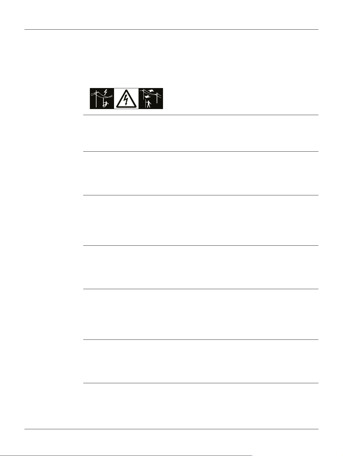
Because of the risk of electrocution, it is dangerous to use poles, levelling staffs and
extensions in the vicinity of electrical installations such as power cables or electrical
railways.
Precautions:
Keep at a safe distance from electrical installations. If it is essential to work in this
environment, first contact the safety authorities responsible for the electrical installations and follow their instructions.
If the product is used with accessories, for example masts, staffs, poles, you may
increase the risk of being struck by lightning.
Precautions:
Do not use the product in a thunderstorm.
Be careful when pointing the product towards the sun, because the telescope functions as a magnifying glass and can injure your eyes and/or cause damage inside the
product.
Precautions:
Do not point the product directly at the sun.
During dynamic applications, for example stakeout procedures there is a danger of
accidents occurring if the user does not pay attention to the environmental conditions
around, for example obstacles, excavations or traffic.
Precautions:
The person responsible for the product must make all users fully aware of the existing
dangers.
WARNING
CAUTION
NOTICE Strong magnetic fields in the immediate vicinity (e.g. transformers, melting
Inadequate securing of the working site can lead to dangerous situations, for example
in traffic, on building sites and at industrial installations.
Precautions:
Always ensure that the working site is adequately secured. Adhere to the regulations
governing safety, accident prevention and road traffic.
Watch out for erroneous measurement results if the product has been dropped or has
been misused, modified, stored for long periods or transported.
Precautions:
Periodically carry out test measurements and perform the field adjustments indicated
in the user manual, particularly after the product has been subjected to abnormal use
as well as before and after important measurements.
furnaces...) may influence the compensator and compass (only LS15) of the instrument and lead to measuring errors.
Precautions:
When working near strong magnetic fields, check results for plausibility.
LS10/LS15, Safety Directions
9
Page 10
CAUTION
If the accessories used with the product are not properly secured and the product is
subjected to mechanical shock, for example blows or falling, the product may be
damaged or people can sustain injury.
Precautions:
When setting up the product, make sure that the accessories are correctly adapted,
fitted, secured, and locked in position.
Avoid subjecting the product to mechanical stress.
CAUTION
WARNING
WARNING
WARNING
During the transport, shipping or disposal of batteries it is possible for inappropriate
mechanical influences to constitute a fire hazard.
Precautions:
Before shipping the product or disposing of it, discharge the batteries by running the
product until they are flat.
When transporting or shipping batteries, the person in charge of the product must
ensure that the applicable national and international rules and regulations are
observed. Before transportation or shipping contact your local passenger or freight
transport company.
High mechanical stress, high ambient temperatures or immersion into fluids can cause
leakage, fire or explosions of the batteries.
Precautions:
Protect the batteries from mechanical influences and high ambient temperatures. Do
not drop or immerse batteries into fluids.
If battery terminals are short circuited e.g. by coming in contact with jewellery, keys,
metallised paper or other metals, the battery can overheat and cause injury or fire, for
example by storing or transporting in pockets.
Precautions:
Make sure that the battery terminals do not come into contact with metallic objects.
If the product is improperly disposed of, the following can happen:
• If polymer parts are burnt, poisonous gases are produced which may impair health.
• If batteries are damaged or are heated strongly, they can explode and cause
poisoning, burning, corrosion or environmental contamination.
• By disposing of the product irresponsibly you may enable unauthorised persons to
use it in contravention of the regulations, exposing themselves and third parties to
the risk of severe injury and rendering the environment liable to contamination.
• Improper disposal of silicone oil may cause environmental contamination.
Precautions:
The product must not be disposed with household waste.
Dispose of the product appropriately in accordance with the national
regulations in force in your country.
Always prevent access to the product by unauthorised personnel.
Product-specific treatment and waste management information can be downloaded
from the Leica Geosystems home page at http://www.leicageosystems.com/treatment or received from your Leica Geosystems dealer.
WARNING
LS10/LS15, Safety Directions
Only Leica Geosystems authorised service centres are entitled to repair these products.
10
Page 11

1.6 Electromagnetic Compatibility EMC
Description The term Electromagnetic Compatibility is taken to mean the capability of the product
to function smoothly in an environment where electromagnetic radiation and electrostatic discharges are present, and without causing electromagnetic disturbances to
other equipment.
WARNING
CAUTION
CAUTION
Electromagnetic radiation can cause disturbances in other equipment.
Although the product meets the strict regulations and standards which are in force in
this respect, Leica Geosystems cannot completely exclude the possibility that other
equipment may be disturbed.
There is a risk that disturbances may be caused in other equipment if the product is
used with accessories from other manufacturers, for example field computers,
personal computers or other electronic equipment, non-standard cables or external
batteries.
Precautions:
Use only the equipment and accessories recommended by Leica Geosystems. When
combined with the product, they meet the strict requirements stipulated by the guidelines and standards. When using computers or other electronic equipment, pay attention to the information about electromagnetic compatibility provided by the manufacturer.
Disturbances caused by electromagnetic radiation can result in erroneous measurements.
Although the product meets the strict regulations and standards which are in force in
this respect, Leica Geosystems cannot completely exclude the possibility that the
product may be disturbed by intense electromagnetic radiation, for example, near
radio transmitters, two-way radios or diesel generators.
Precautions:
Check the plausibility of results obtained under these conditions.
CAUTION
Bluetooth Use of product with Bluetooth:
WARNING
If the product is operated with connecting cables attached at only one of their two
ends, for example external supply cables, interface cables, the permitted level of electromagnetic radiation may be exceeded and the correct functioning of other products
may be impaired.
Precautions:
While the product is in use, connecting cables, for example product to external battery,
product to computer, must be connected at both ends.
Electromagnetic radiation can cause disturbances in other equipment, in installations,
in medical devices, for example pacemakers or hearing aids and in aircraft. It can also
affect humans and animals.
Precautions:
Although the product meets in combination with radio or digital cellular phone devices
recommended by Leica Geosystems the strict regulations and standards which are in
force in this respect, Leica Geosystems cannot completely exclude the possibility that
other equipment may be disturbed or that humans or animals may be affected.
• Do not operate the product with radio or digital cellular phone devices in the vicinity
of filling stations or chemical installations, or in other areas where an explosion
hazard exists.
• Do not operate the product with radio or digital cellular phone devices near to
medical equipment.
• Do not operate the product with radio or digital cellular phone devices in aircraft.
LS10/LS15, Safety Directions
11
Page 12
1.7 FCC Statement, Applicable in U.S.
WARNING
WARNING
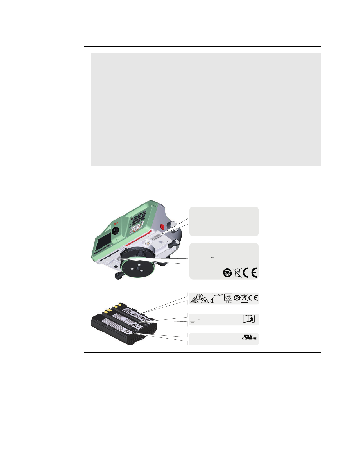
Labelling LS10/LS15
The greyed paragraph below is only applicable for products without radio.
This equipment has been tested and found to comply with the limits for a Class B
digital device, pursuant to part 15 of the FCC rules.
These limits are designed to provide reasonable protection against harmful interference in a residential installation.
This equipment generates, uses and can radiate radio frequency energy and, if not
installed and used in accordance with the instructions, may cause harmful interference
to radio communications. However, there is no guarantee that interference will not
occur in a particular installation.
If this equipment does cause harmful interference to radio or television reception,
which can be determined by turning the equipment off and on, the user is encouraged
to try to correct the interference by one or more of the following measures:
• Reorient or relocate the receiving antenna.
• Increase the separation between the equipment and the receiver.
• Connect the equipment into an outlet on a circuit different from that to which the
receiver is connected.
• Consult the dealer or an experienced radio/TV technician for help.
Changes or modifications not expressly approved by Leica Geosystems for compliance
could void the user's authority to operate the equipment.
Labelling Internal
Battery GEB331
010763_001
008469_003
Contains transmi tter mod ule :
FCC-I D T7VE BMU / IC : 6850A -31308
This device c omplies with p art 15 of the FCC Ru les. Opera tion is subjec t to
the followi ng two condit ions: (1) Thi s device may not cau se harmful
interference, and (2) This device must accept any interference received,
includin g interfere nce that may caus e undesired op eration.
Type: LS1X 0.Xmm
Equip.No.: 12 345 67
Power: 12V-18V , 4.0W max
Made in Singapore
Manufactured: 20X X
Leica Geosystems AG
CH-9435 Heerbrugg
Type: GEB331
Li-Ion Battery
11.1 V / 2.8 Ah
15 A / 31.1 Wh
Leica Ge osystems AG, CH -9435 Heerbrugg
This device complies with part 15 of the FCC Rules.
Operation is subject to the following two conditions:
(1) This device may not cause harmful interference, and
(2) this device must accept any interference received,
including interference that may cause undesired operation.
Art.No.: 799190
S.No.: XXXXX
Made in China
Art.No.:
123456
S.No.:
123456
11WE
MH29443
LS10/LS15, Safety Directions
12
Page 13
2 Description of the System
2.1 System Components
Main Components
Features of
LS10/LS15
Component Description
LS10/LS15
instrument
Standard
applications
Infinity
software
Data transfer Data can be transferred between the instrument and a computer via
Feature LS10 LS15
Height measurement
Distance measurement
Magnetically damped compensator
32x Magnification telescope
Manual focus
Autofocus -
Overview camera -
Compass -
MapView / Coordinates for office export -
Mechanical bubble
Electronic bubble / Tilt check
Communication (USB host, USB device)
Bluetooth
RS232/USB Lemo connector interface -
Internal flash memory for 30.000 measurements
An instrument for measuring, calculating and capturing data. Ideally
suited for measurement tasks such as single height measurements,
line levelling jobs, adjustment of point heights or staking out heights.
Equipped with a package of standard applications to complete these
tasks.
All standard applications are already installed on the instrument.
Standard applications include Q-Level, Line Levelling, Line Adjustment, Intermediate, Set Out and additional Tools features.
An office software consisting of a suite of standard and extended
programs for the viewing, exchanging, managing and post
processing of data.
a data transfer cable, a USB memory stick, a USB cable or Bluetooth.
Available - Not available
LS10/LS15, Description of the System
13
Page 14
2.2 Container Contents
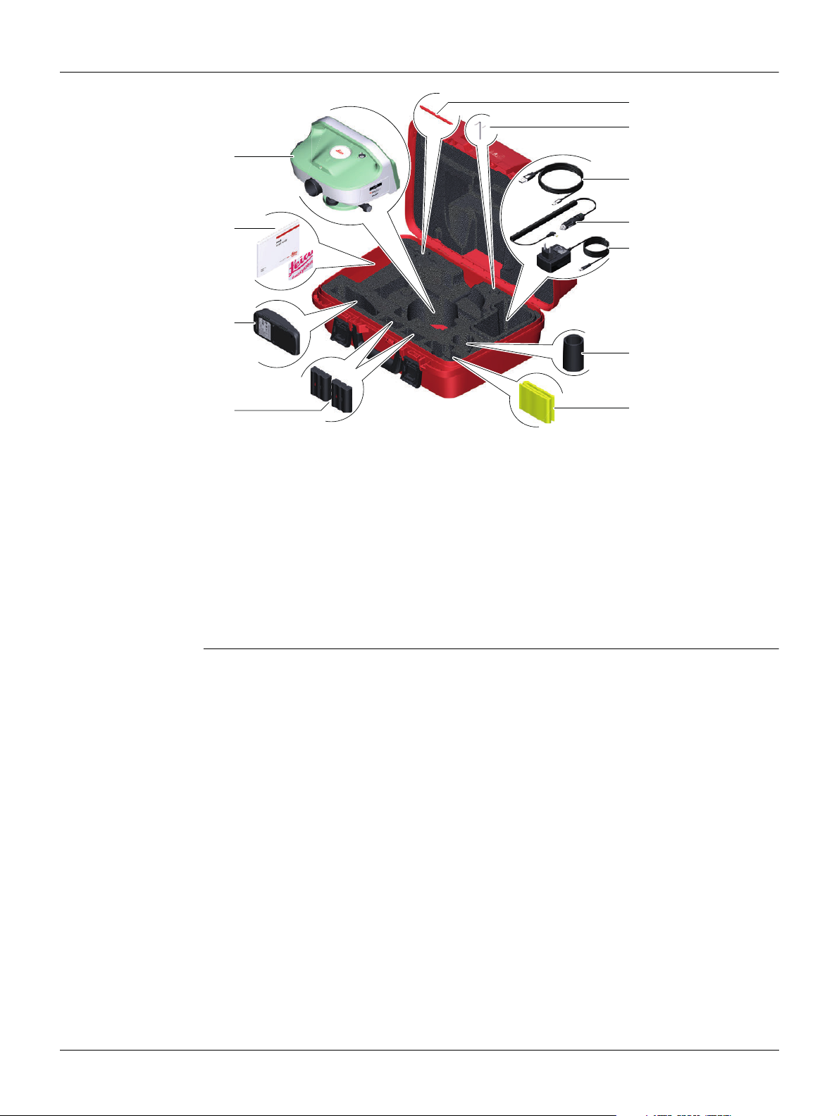
Container Contents
a
b
c
d
010043_001
a) Instrument
b) Quick Guide/USB documentation card
c) GKL311 battery charger (optional)
d) GEB331 batteries (optional)
e) Spare stylus (optional)
f) Allen keys (1.5 mm/2 mm)
g) GEV223 USB data transfer cable (optional)
h) Car adapter cable for GKL311 (optional)
i) GEV192 AC power adapter for GKL311 (optional)
j) Sunshade
k) Rain Cover
e
f
g
h
i
j
k
LS10/LS15, Description of the System
14
Page 15
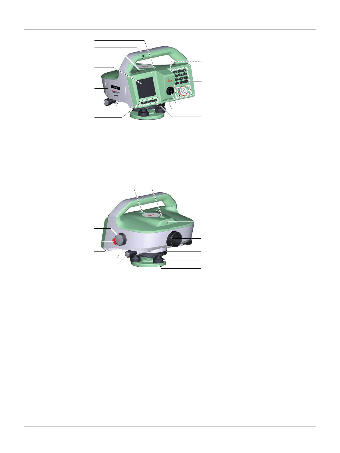
2.3 Instrument Components
Instrument
Components
(Part 1)
Instrument
Components
(Part 2)
a
b
c
d
e
f
g
h
010044_002
a
b
c
d
e
f
010045_002
i
b) Handle with integrated prism
for viewing the circular level
c) Circular level
a) Optical sight
j
d) Touchscreen
e) Battery compartment, also
containing interface for
k
l
m
USB stick and Mini USB
f) Horizontal drive
g) Push button to open battery
compartment
h) Function keys
i) ON/OFF key
j) Keyboard
k) Eyepiece
l) Protective cap for crosshair
adjustment screw
m) Horizontal circle
a) Optical sight
b) Focussing drive
c) Trigger key
d) Stylus for touchscreen
g
e) RS232 serial/USB interface with
external power supply
(only LS15)
h
f) Horizontal drive
g) Overview camera (only LS15)
i
j
k
h) Objective
i) Horizontal circle
j) Footscrews
k) Base plate
LS10/LS15, Description of the System
15
Page 16
3User Interface
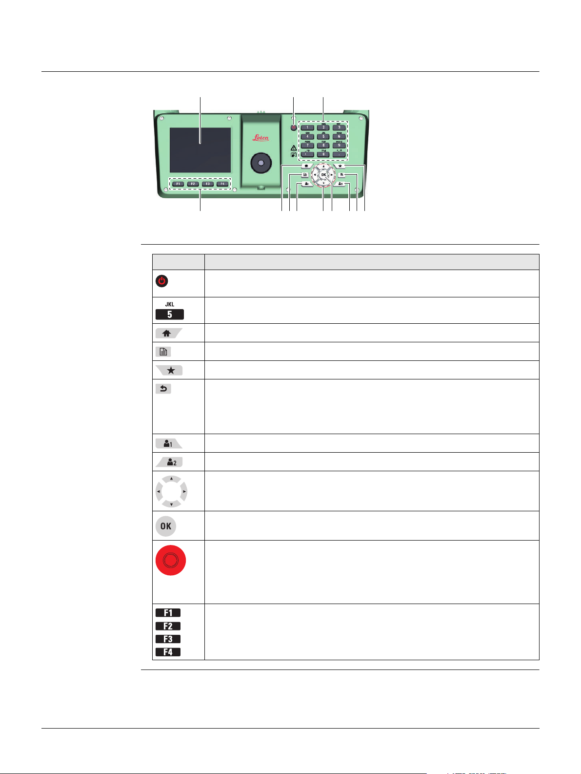
3.1 Keyboard
Keyboard
Keys
a
010046_002
Key Description
d
ON/OFF key to switch the instrument on or off or to set it into standby
mode.
Alphanumeric keypad for entering text and numerical values.
Home key. Returns to the Main Menu.
Page key. Displays the next screen when several screens are available.
Favourites key. Quick-access to measurement supporting functions.
cb
ije fg h kl
a) Touchscreen
b) ON/OFF key
c) Alphanumeric keypad
d) Function keys F1 to F4
e) Home key
f) Page key
g) User key 1
h) Navigation keys
i) Enter key
j) User key 2
k) ESC key
l) Favourites key
ESC key (in general): Quits a screen or edit mode without saving changes.
Returns to next higher level.
ESC key (in all levelling applications): After confirming the action, the ESC
key deletes the last observation and allows to repeat it.
User key 1. Programmable with a function from the Favourites menu.
User key 2. Programmable with a function from the Favourites menu.
Navigation keys. Control the focus bar within the screen and the entry bar
within a field.
ENTER key. Confirms an entry and continues to the next field.
Trigger key. Triggers a measurement. Programmable with functions which
allow the auto-focussing of the telescope (only LS15), the height and
distance reading and the storing of the measurement data.
For details on how to define the functions of trigger key, refer to "6.1
Work Settings".
Function keys that are assigned to the variable functions displayed at the
bottom of the screen.
LS10/LS15, User Interface
16
Page 17
3.2 Operating Principles
Edit Fields with
Alphanumeric
Keypad
Select a Menu
Option with
Alphanumeric
Keypad
Use the alphanumeric keypad to enter characters directly into editable fields.
• Numeric fields: Can only contain numerical values. Press a key of the keypad to
enter a number.
• Alphanumeric fields: Can contain numbers and letters. Press a key of the keypad
to enter one of the characters written above that key. To toggle through the characters, press the key several times until the required character is displayed. For
example: A>B>C>2>A>B>...
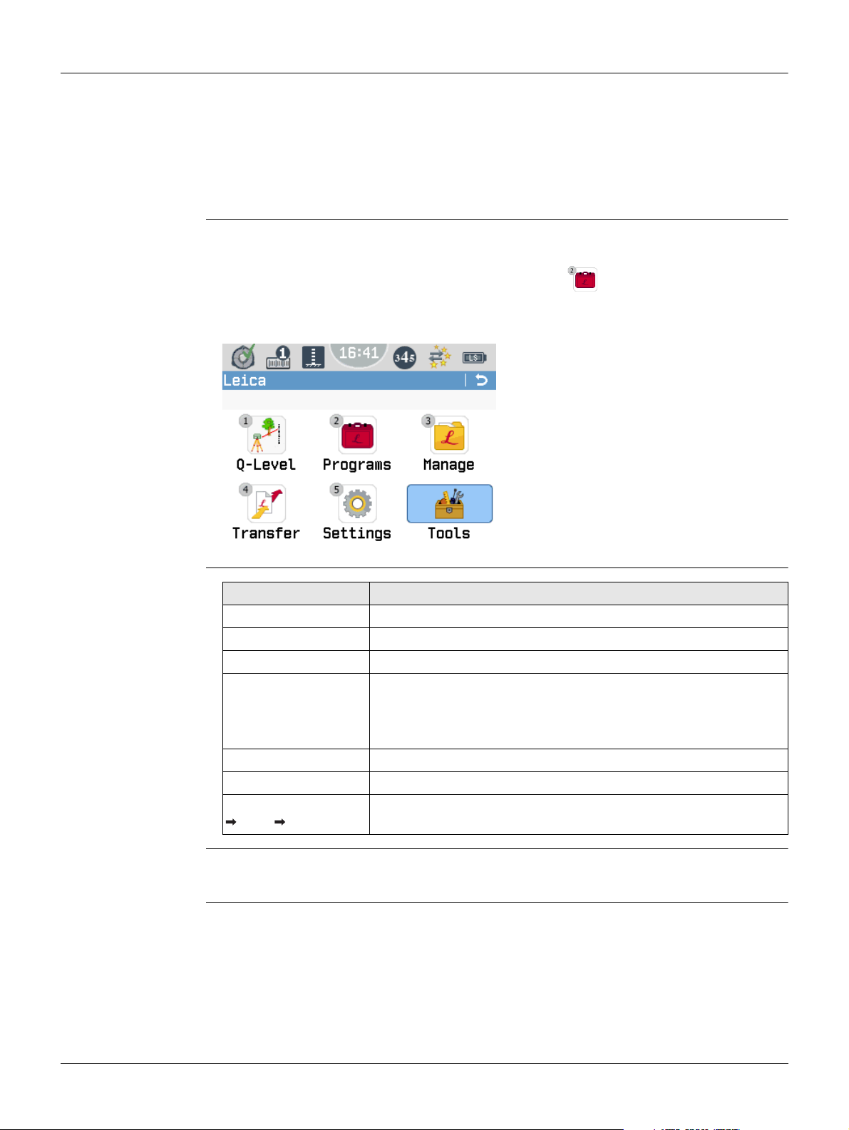
Within the menu screens, you can select a menu option by pressing a key on the alphanumeric keyboard. To select a menu option, press the respective number that is
displayed at the upper left corner of the menu icon .
Example:
Press 2 on the alphanumeric
keyboard to open the menu
Programs.
Keys for Editing
Input Fields
Key Description
ESC key Deletes any change and restores the previous value.
Left navigation key Moves the cursor to the left.
Right navigation key Moves the cursor to the right.
Softkey Insert If alphanumeric mode is activated: Inserts a whitespace at the
cursor position.
If numeric mode is activated: Inserts zero at the cursor posi-
tion.
Softkey Delete Deletes the character at the cursor position.
Softkey Clear Deletes all characters entered into the input field.
Softkey
ABC/ 123
In edit mode the position of the decimal place cannot be changed. The decimal place
is skipped.
Switches between alphanumeric and numeric mode.
LS10/LS15, User Interface
17
Page 18
Special Characters
007928_001_en
a
b
c
d
e
Character Description
* Used as wildcard in search fields for point IDs or codes. Refer to "7.1.2
+/- In the alphanumeric character set "+" and "-" are treated as normal
3.3 Screen
Pointsearch".
alphanumeric characters with no mathematical function.
"+" / "-" only appear in front of an entry.
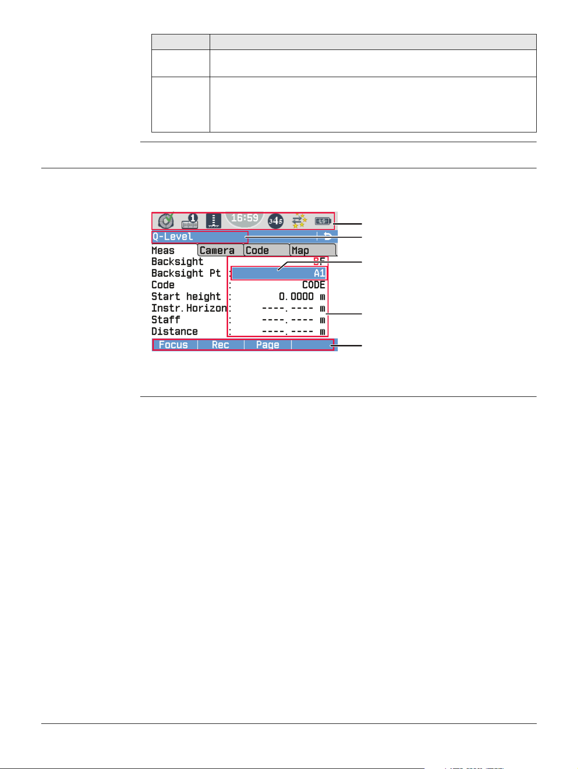
Colour and Touch
Screen
All screens shown in this manual are examples. It is possible that firmware
versions in local languages are different to the English version.
a) Status icons
b) Title of screen
c) Focus in screen (active field)
d) Input and output fields
e) Softkeys
The screen is touch-sensitive and optimised for operation with the supplied
stylus. Tap on an icon, field or tab to run a function.
LS10/LS15, User Interface
18
Page 19
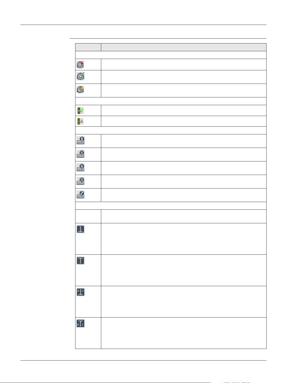
3.4 Status Icons
Description The icons provide status information related to basic instrument functions.
Icons
Icon Description
Tilt Check on LS15
Tilt Check is off. Tap the icon to open the Level & Tilt Check screen.
The instrument is levelled and Tilt Check is on. Tap the icon to open the
Level & Tilt Check screen.
Instrument needs to be levelled before a measurement can be performed.
Tap the icon to open the Level & Tilt Check screen.
Tilt Check on LS10
Instrument is levelled. Tap the icon to open the Level screen.
Instrument needs to be levelled. Tap the icon to open the Level screen.
Measurement Mode
Measurement mode is set to Single. Tap the icon to open the Mode
Settings screen.
Measurement mode is set to Mean. Tap the icon to open the Mode
Settings screen.
Measurement mode is set to Mean S. Tap the icon to open the Mode
Settings screen.
Measurement mode is set to Median. Tap the icon to open the Mode
Settings screen.
Measurement mode is set to Tracking. Tap the icon to open the Mode
Settings screen.
Orientation of Staff and Status of Earth Curvature Correction
The orientation of the staff is set to upright. It is only possible to take
measurements with the 0-mark at the bottom of the staff. Tap the icon
to change the orientation to inverse.
The earth curvature correction is set to Off. Refer to "6.2 Regional
Settings" for details on how to set the earth curvature correction to On.
The orientation of the staff is set to inverse. It is only possible to take
measurements with the 0-mark at the top of the staff. The measured
values are negative. Tap the icon to change the orientation to upright.
The earth curvature correction is set to Off. Refer to "6.2 Regional
Settings" for details on how to set the earth curvature correction to On.
The orientation of the staff is set to upright. It is only possible to take
measurements with the 0-mark at the bottom of the staff. Tap the icon
to change the orientation to inverse.
The earth curvature correction is set to On. Refer to "6.2 Regional
Settings" for details on how to set the earth curvature correction to Off.
The orientation of the staff is set to inverse. It is only possible to take
measurements with the 0-mark at the top of the staff. The measured
values are negative. Tap the icon to change the orientation to upright.
The earth curvature correction is set to On. Refer to "6.2 Regional
Settings" for details on how to set the earth curvature correction to Off.
Within the Check & Adjust application, the earth curvature correction is automatically set to On.
LS10/LS15, User Interface
19
Page 20
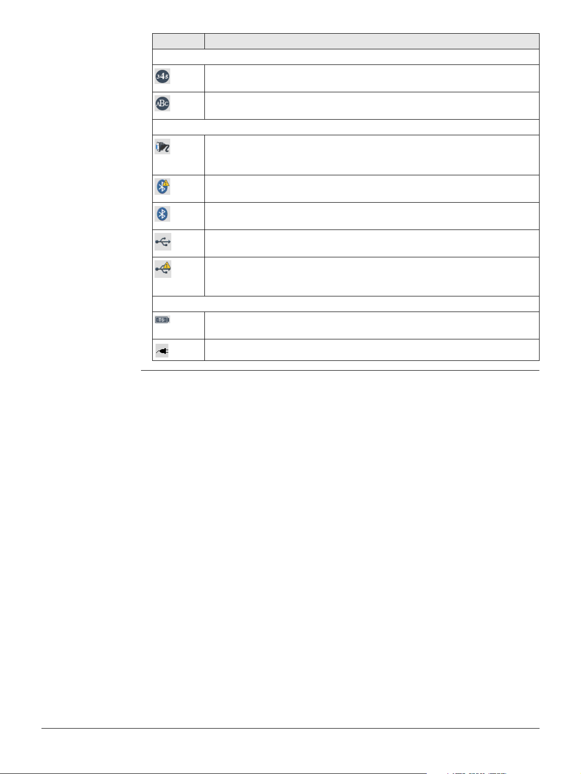
Icon Description
Keypad Mode
Keypad is set to numeric mode. Tap the icon to switch to alphanumeric
mode or use the softkey ABC.
Keypad is set to alphanumeric mode. Tap the icon to switch to numeric
mode or use the softkey 123.
Interface Setting
Only available on LS15 instrument:
RS232 communication port is selected. Tap the icon to open the Interface
Settings screen.
Bluetooth communication port is selected, but inactive. Tap the icon to
open the Interface Settings screen.
Bluetooth communication port is selected and active. Tap the icon to
open the Interface Settings screen.
Either Mini USB or Lemo USB (only LS15) communication port is configured and connected. Tap the icon to open the Interface Settings screen.
Either Mini USB or Lemo USB (only LS15) communication port is configured but disconnected. Tap the icon to open the Interface Settings
screen.
System Status
The battery symbol indicates the level of the remaining battery capacity,
100% full shown in the example. Tap the icon to open the Info screen.
The instrument is connected to an external power supply.
LS10/LS15, User Interface
20
Page 21
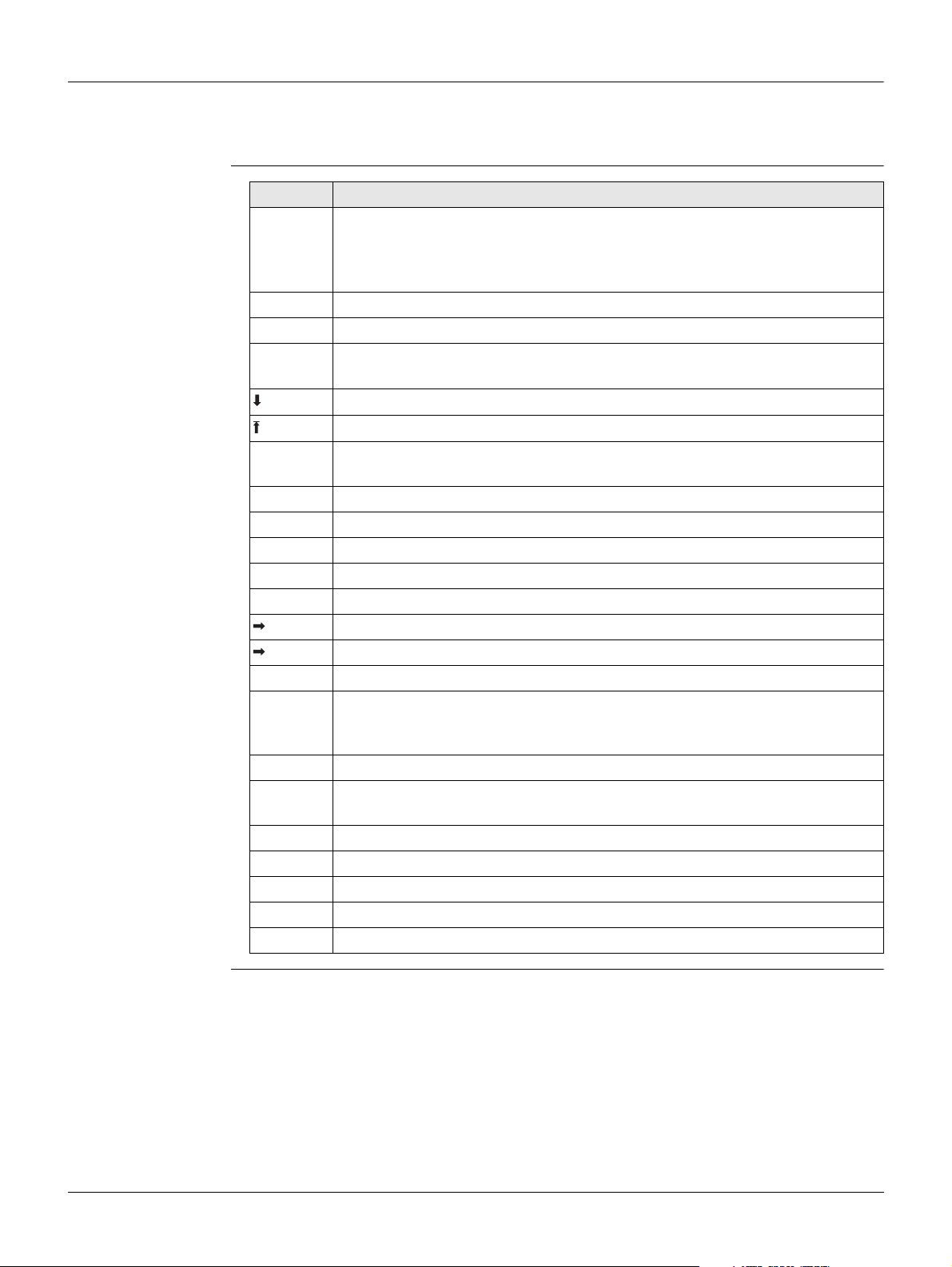
3.5 Softkeys
Description Softkeys are selected using the relevant F1 to F4 function key. This chapter describes
the functionality of the common softkeys used by the system. The more specialised
softkeys are described where they appear in the program chapters.
Common Softkey
Functions
Key Description
Cont If entry screen: Confirms measured or entered values and continues the
process.
If message screen: Confirms message and continues with selected action
or returns to the previous screen to reselect an option.
Back To return to the last active screen.
Page To change to the next page within a menu, program or settings screen.
Yes/No To confirm or reject a warning or information message on a message
screen.
To display the lower softkey level.
To return to the upper softkey level.
Default/R
eset
New To create a job, fixpoint or code.
Edit To edit existing values or data.
Insert To insert zero within an entry field.
Delete To delete a single character within an entry field.
Clear To delete all characters within an entry field.
ABC To change the keypad operation to alphanumerical.
345 To change the keypad operation to numerical.
Focus To focus to the staff with auto-focus mode (only available on LS15).
Dist To take a height and distance reading. Note: The values measured by
Rec To store the measured data and continue the process.
SetOut To switch to the screen for setting out heights, height differences or
INT To switch to the screen for surveying intermediate points.
ENH To open the manual coordinate entry screen.
Find To search for fixed points or measurements.
List To display the list of available points.
View To display the coordinate and job details of the selected point.
To reset all editable fields to their default values.
pressing Dist (softkey F2) are not stored to the job. To measure and store
use the trigger key.
distances.
LS10/LS15, User Interface
21
Page 22
4Operation
5
4b
4c
3
4a
2b
2a
4.1 Power Supply
4.1.1 Working with the Battery
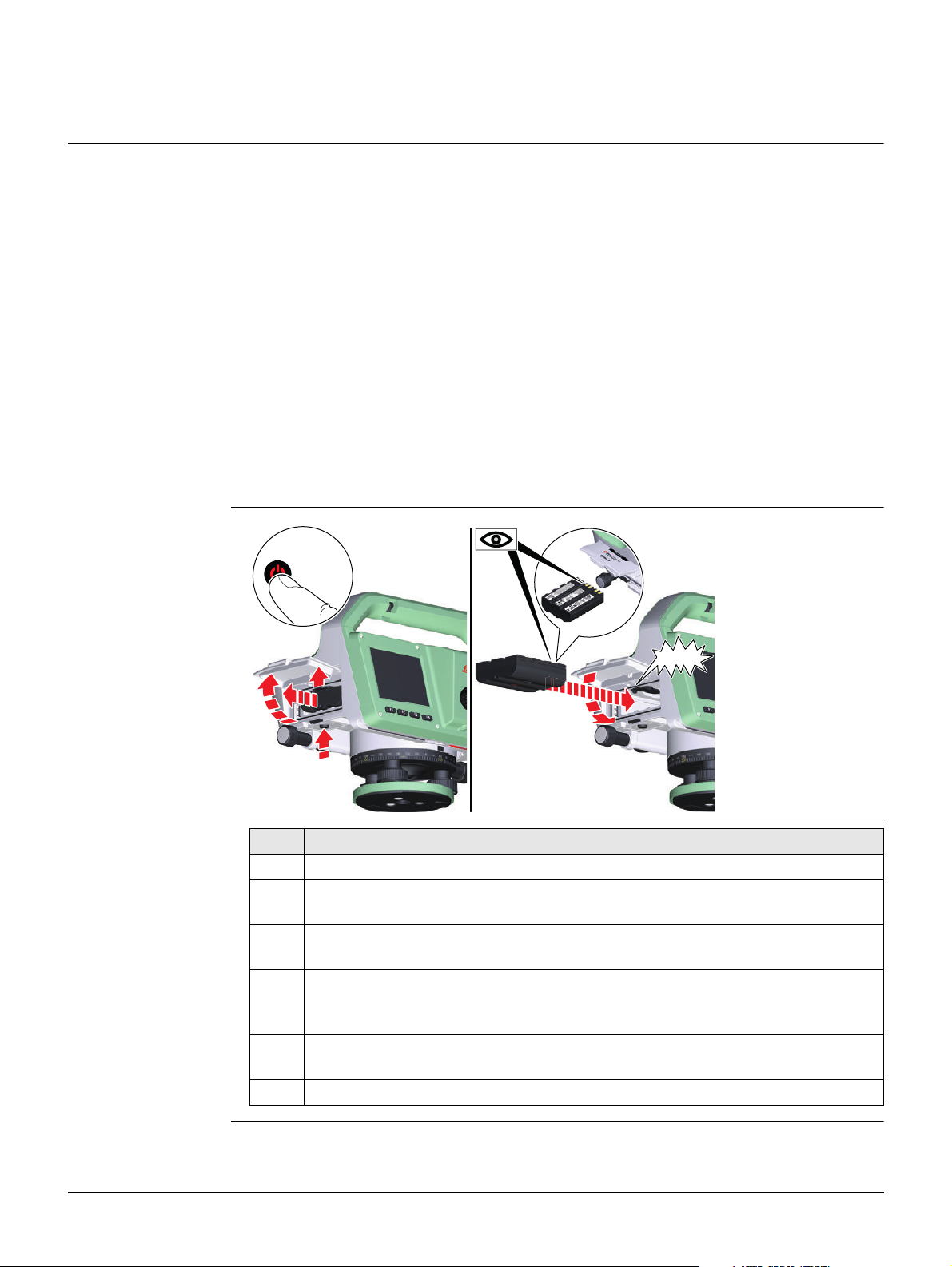
Change the Battery
Step-by-Step
Charging / first-time use
• The battery is delivered in a sleep mode and needs to be activated before using it
for the first time. To activate, charge the battery. For more information, refer to
the documentation supplied with the battery.
• The permissible temperature range for charging is between 0°C to +45°C/+32°F to
+113°F. For optimal charging we recommend charging the batteries at a low
ambient temperature of +10°C to +30°C/+50°F to +86°F if possible.
• It is normal for the battery to become warm during charging. Using the chargers
recommended by Leica Geosystems, it is not possible to charge the battery if the
temperature is too high.
Operation / discharging
• The batteries can be operated from -30°C to +60°C/-22°F to +140°F.
• Low operating temperatures reduce the capacity that can be drawn; very high operating temperatures reduce the service life of the battery.
• For Li-Ion batteries, we recommend carrying out a single discharging and charging
cycle when the battery capacity indicated on the charger or on a Leica Geosystems
product deviates significantly from the actual battery capacity available.
1
OFF
4b
5
2b
010047_001
4a
3
2a
6
click
4c
Step Description
1. Turn off the instrument.
2. To open the battery compartment, press the push button that is underneath
the battery compartment.
3. To release the battery from the compartment, push the latch securing the
battery upwards.
4. Take the battery out of the compartment and insert a charged battery.
Insert the battery with the contacts facing upwards and towards the
instrument.
5. Push the battery into the compartment until the latch snaps back to its position.
6. Close the battery compartment.
LS10/LS15, Operation
22
Page 23
4.2 Data Storage
Description The instrument is equipped with an internal memory. In the internal memory, all data
is stored within jobs in the database. From the database, you can transfer or export
the data and convert it into a readable format (e.g. ASCII, HexML, GSI) by using the
transfer functionality.
For further information on data management and data transfer refer to "13 Data
Management".
4.3 Instrument Setup
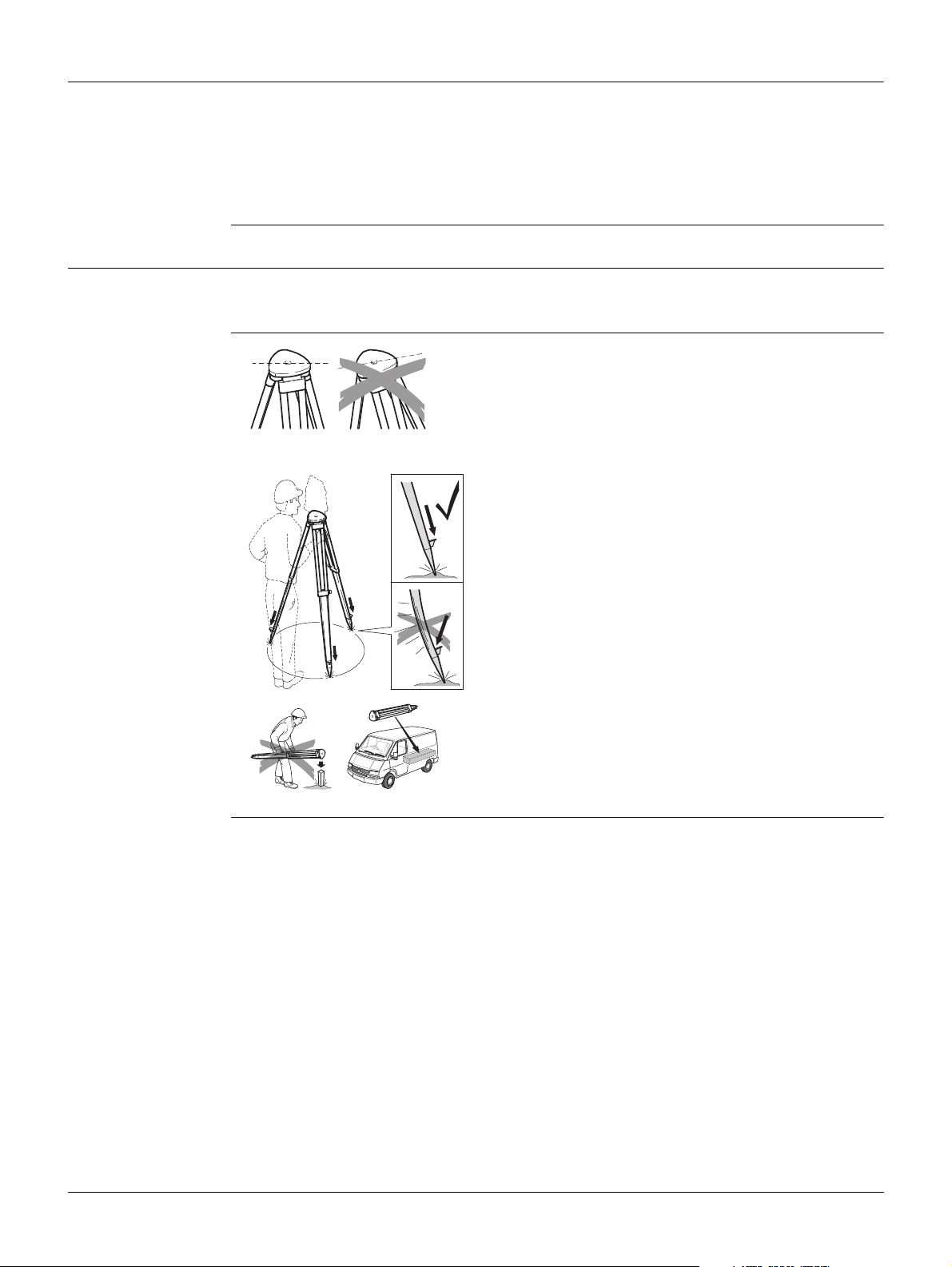
Tripod
For highest accuracy levelling tasks, use a tripod with fixed legs, for example 328422
GST40.
When setting up the tripod pay attention to
ensuring a horizontal position of the tripod
plate. Slight corrections of inclination can
be made with the foot screws of the
tribrach. Larger corrections must be done
with the tripod legs.
Loosen the clamping screws on the tripod
legs, pull out to the required length and
tighten the clamps.
a) In order to guarantee a firm foothold
sufficiently press the tripod legs into the
ground.
b) When pressing the legs into the ground
note that the force must be applied along
the legs.
Careful handling of tripod.
• Check all screws and bolts for correct fit.
• During transport, always use the cover
supplied.
• Use the tripod only for surveying tasks.
TSOX_012b
TSOX_012a
TSOX_012c
a
b
LS10/LS15, Operation
23
Page 24
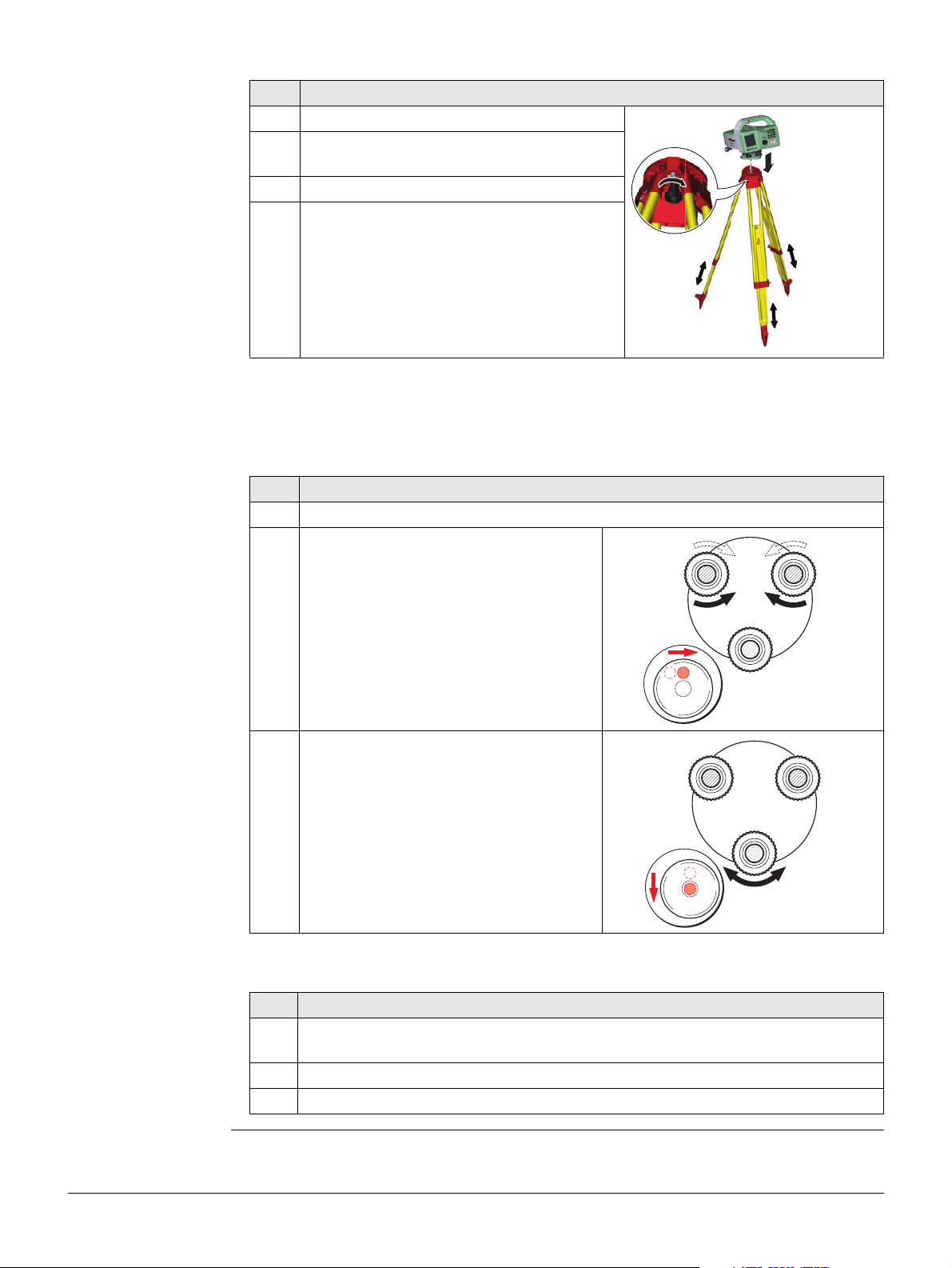
Setup Step-by-Step Setting up the Instrument on the Tripod
4
Step Description
1. Set up the tripod.
2. Extend the tripod legs to allow for a
comfortable working posture.
3. Fasten the instrument onto the tripod.
4. Tighten the central fixing screw.
Centring the Circular Level Manually
The circular level helps you to level up the instrument manually. To level up the instrument precisely, you can also use the electronic level. Refer to 4.4" For LS15: Level Up
with the Electronic Level Step-by-Step".
Step Description
1. Turn the instrument, so that the ocular is positioned above footscrew C.
2. Turn the footscrews A and B simultaneously in opposite directions until the
bubble is on the middle axis of the
circular level.
4
4
2
010756_001
AB
3
1
2
2
C
007898_001
3. Turn the footscrew C until the bubble is
centred.
AB
C
007899_001
Adjusting the Reticle to the Eyesight of the User
Step Description
1. Point the telescope towards a bright background.
To ensure a parallax free sight for optical readings of a staff, you need to
adjust the reticle to the eyesight of the user.
2. Turn the ocular until the reticle is focussed and appears sharp and black.
LS10/LS15, Operation
24
Page 25
4.4 Startup
Turn Instrument
On/Off or Enable
Standby Mode
Select a Language After turning on the instrument, you can choose the preferred language. The language
For LS15: Level Up
with the Electronic
Level Step-by-Step
To turn the instrument on, press the ON/OFF key for 2 seconds.
To turn off the instrument or set it into standby mode, press the ON/OFF key and
select the appropriate option from the information screen.
choice screen is only shown if multiple languages are loaded onto the instrument and
Lang.Choice: On is set in the instrument settings. Refer to "6.2 Regional Settings".
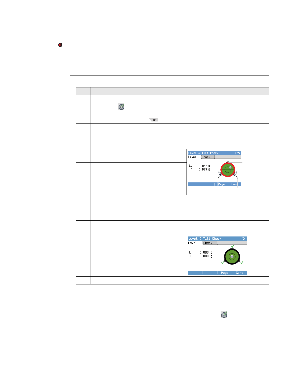
The electronic level allows you to precisely level up the instrument.
Step Description
1. Turn on the instrument.
Tap on the Level & Tilt Check icon.
OR
Press the Favourites key from within any program and select Level.
2. Turn the instrument, so that the ocular is
positioned above footscrew C.
3. Turn the footscrews A and B simultane-
ously in opposite directions until the
bubble of the electronic level is approximately on the middle axis.
The bubble of the electronic level and the arrows for the rotating direction of the footscrews only appear if the instrument tilt is within the
sensors working range. To roughly level the instrument, centre the
bubble of the circular level first. Refer to "4.3 Instrument Setup".
C
AB
Activating Tilt Check
4. Centre the bubble of the electronic level for the second axis by turning the
footscrew C. An arrow shows the direction of rotation required.
5. Accept with Cont.
To activate or deactivate the Tilt Check functionality, tap on the Level & Tilt Check
icon and press the softkey Page (F3). On the Check page, select On or Off and press
the softkey Cont.
If you activate the Tilt Check functionality, the instrument checks the longitudinal and transversal tilt before taking a measurement. If the instrument needs
to be levelled again, a warning message is displayed.
When levelled correctly, check marks are displayed. If the tilt of the
instrument exceeds 0.0700gon/0.0630°, the electronic level is out of
its working range and therefore, the frame becomes red. Once the level
is within the working range, the frame becomes black.
When the bubble is centred and
the check marks are displayed,
the instrument has been
perfectly levelled up.
LS10/LS15, Operation
25
Page 26
For LS10: Level Up
with the Electronic
Level Step-by-Step
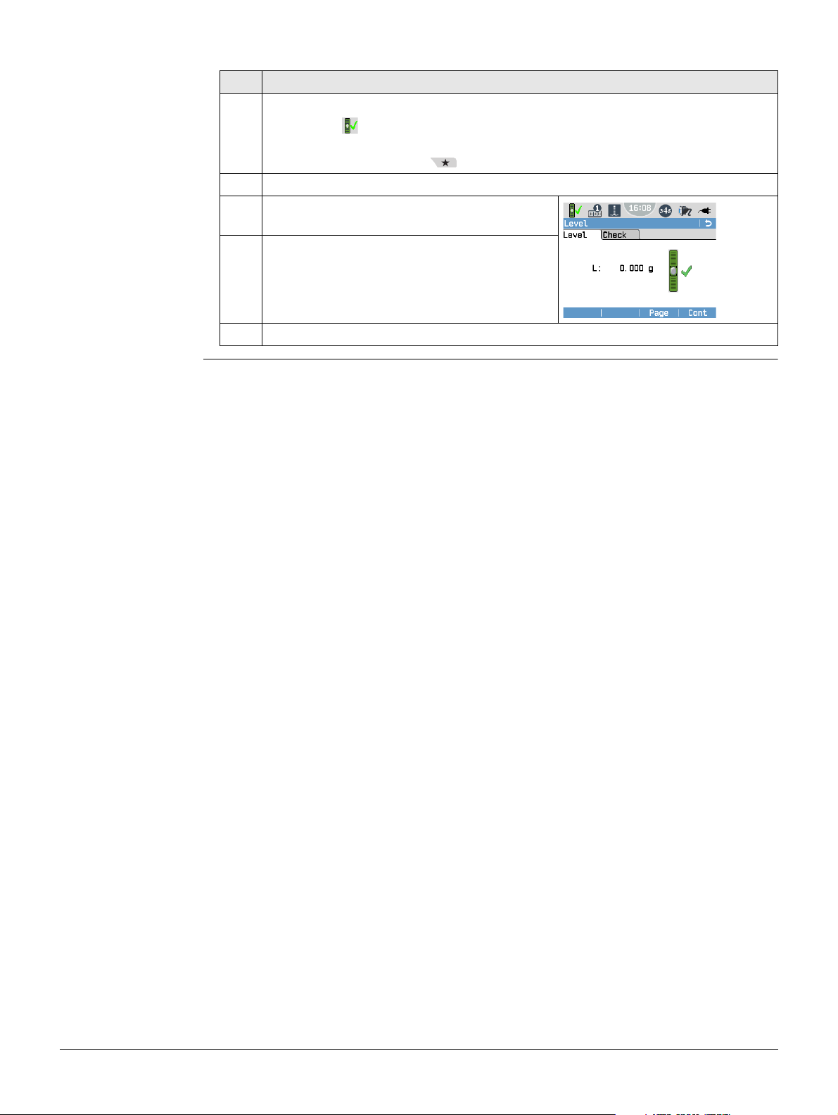
The electronic level allows you to precisely level up the instrument.
Step Description
1. Turn on the instrument.
Tap on the Level & Tilt Check icon.
OR
Press the Favourites key from within any program and select Level.
2. Centre the bubble of the circular level as described in "4.3 Instrument Setup".
3. To centre the bubble of the electronic
tubular level, turn the footscrew C.
4. Accept with Cont.
When a checkmark is displayed, the
instrument has been correctly
levelled up.
LS10/LS15, Operation
26
Page 27
4.5 Main Menu
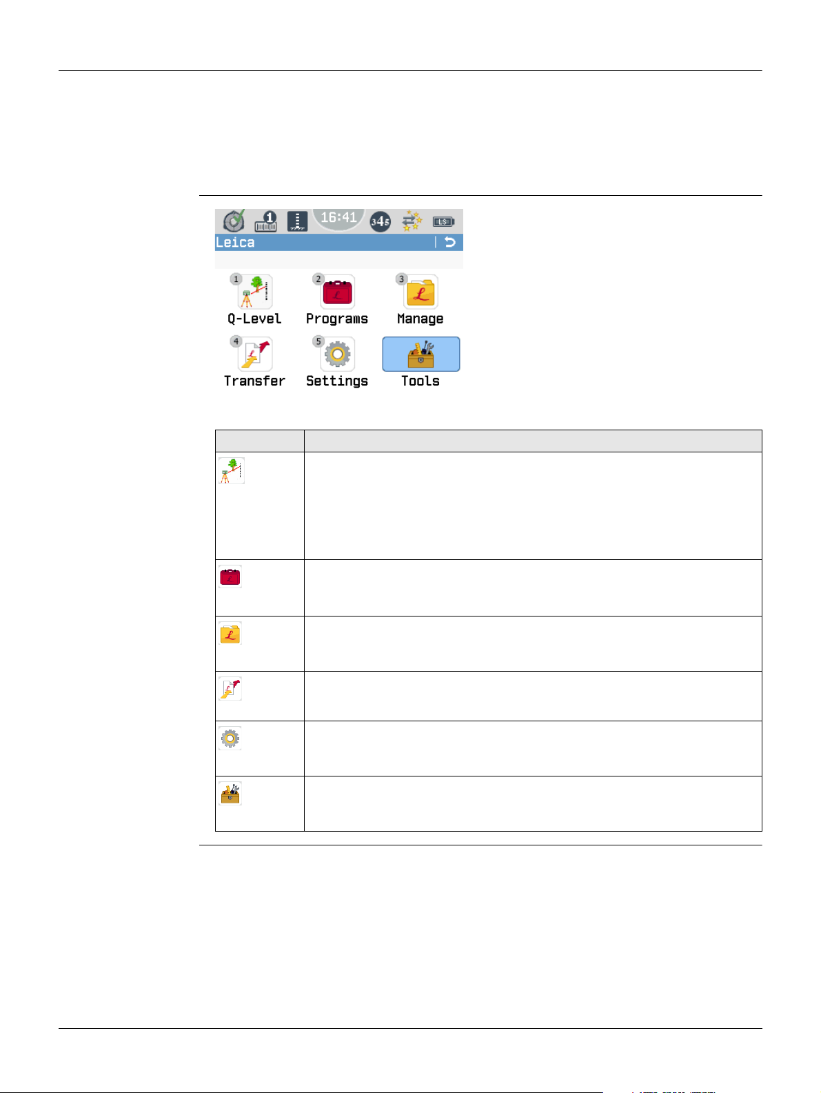
Description The Main Menu is the starting place for accessing all functionality of the instrument.
Main Menu
Description of the Main Menu functions
Function Description
Q-Level
Programs
Manage
Transfer
Settings
Tools
If desired, you can configure the instrument to start with a user-defined screen
instead of the Main Menu. Refer to "6.1 Work Settings".
For the LS15, it is recommended to define the Compass Calib application as
starting screen. To allow the visualisation of levelling lines within the office
software, the compass should be calibrated on each instrument startup.
Q-Level (Quick Level): a line levelling program to start right away. Each
time you access Q-Level, a new Line is started and ended when you
exit the application.
For details refer to "7.2 Q-Level Program".
To select and start the programs BasicLevel, LineLevel and LineAd-
just.
For details refer to "7 Programs".
To manage jobs, data, codelists and formats in the internal memory as
well as files stored on the USB memory stick. Refer to "13 Data
Management".
To export and import data. Refer to "13.2 Exporting Data"or "13.3
Importing Data".
To change Work or Regional settings and to select communication
parameters. To change general instrument settings such as measurement modes and interface settings. Refer to "6 Settings".
To access instrument-related tools such as check and adjust, personal
startup settings, PIN code settings, licence keys, system information
and firmware upload. Refer to "12 Tools".
You cannot adjust lines that are measured with the Q-Level
application.
LS10/LS15, Operation
27
Page 28

5 Measurement Guidelines
5.1 General Measurement Guidelines
General Guidelines Selecting a Staff
The measuring accuracy depends on the staff that is used in combination with the
instrument. Use standard staffs for medium range of accuracy and (calibrated) Invar
levelling staffs (for example GPCL3) for highest precision.
Preparing a Measurement
• Allow the instrument to acclimatise to the ambient temperature. Wait approxi-
• When working under strong sunlight with the instrument remaining on one station
• Keep the optics clean. Dirt or condensation on the optics can affect measurements.
• Check and adjust the instrument regularly; especially after long storage periods,
• Depending on the planned measurement task, set or change relevant instrument
Taking a Measurement
• Maintain approximately the same target distance for back- and foresight. At the
• Measure foresights and backsights. When closing a line at a known end point, check
Taking a Precision Measurement
• Limit the target distance to ≤ 30 m.
• Ensure a minimum ground clearance of 0.5 m to minimise the influence of refrac-
• Apply double observation methods, such as BFFB or aBFFB, to increase the relia-
• Apply alternating observation methods (aBFFB = BFFB FBBF) to eliminate the hori-
• When taking measurements near the edge of the staff, the reduced number of
Visual Control of the Staff
When looking through the telescope, e.g. for visual control while taking a measurement, a low intensity red blinking LED light may be visible, especially when measuring
in low light surrounding. This LED light is used in the illumination of the compensator
and has no impact on the eye safety of the user.
When using an Invar levelling staff, adjust the Staff Select setting to maintain
highest precision. Refer to "6.1 Work Settings".
mately 2 minutes per °C of temperature difference.
for a long time, for example when measuring or setting out a grid, use an umbrella
to shield the instrument and the tripod.
after transportation or before an upcoming high precision levelling task. Refer to
"14 Check & Adjust"
parameters, such as earth curvature correction or measurement mode.
end of a line, check if the sum of all foresights equals the sum of all backsights.
the misclosure between the measured total delta height and the delta height calculated from the difference between start and end-point height.
tions due to ground proximity.
bility of the measurement and to reduce possible errors caused by the staff sinking.
zontal tilt. The horizontal tilt is the residual error of the automatic compensator.
staff code elements may slightly lower the measuring accuracy. To maintain highest
accuracy, activate the precision mode in the tolerance settings of the LineLevel
program. When activated, the instrument monitors whether the height reading is
within 0.50 m to either end of the staff (top and bottom). The top and bottom
limits of the staff are automatically converted to a 3 m Invar staff. In order to use
different staff sizes, you can manually adjust the limit values.
The precision mode also monitors critical distances between the instrument and
the staff. These distances depend on the physical properties of the staff code. The
measuring accuracy of height measurements within these distance ranges may also
be slightly lower. A warning is displayed if the measuring distance is within the
following ranges: 13.250 m - 13.500 m and 26.650 m - 26.900 m. If the instrument detects a staff distance within these ranges, slightly move the staff out of
the mentioned measurement range in order to maintain highest measurement
accuracy expectations.
LS10/LS15, Measurement Guidelines
28
Page 29
5.2 Guidelines for Special Measurement Situations
Special
Measurement
Situations
Vibrations
Touch the upper third of the tripod to reduce the vibrations at the instrument, for
example caused by wind.
Back light
Low sunlight may influence the ability of the instrument to read the staff. Use the
sunshade delivered with the instrument to shield the objective.
Darkness
When working in darkness (for example tunnelling), evenly illuminate the measuring
area of the staff with a flashlight or a spotlight or use a special self-illuminated staff
(for example Nedo Lumiscale).
Measuring at the lower end of the staff
Measurements slightly below the zero point of a staff are possible and will result in
negative measurement values.
Measuring at the upper end of the staff
When measuring at the upper end of the staff, use staffs with the following lengths:
•4.05m
•2.95m
•2.70m
•1.95m
•1.82m
With other staff lengths, measurements at the upper end of the staff are not possible.
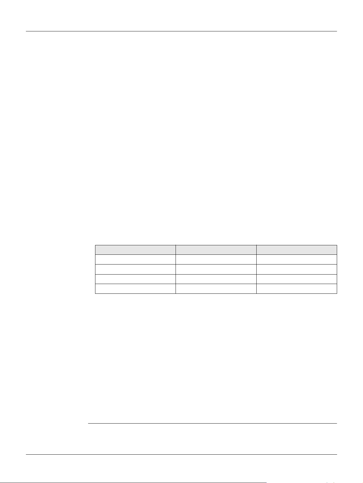
Code length required in the field of view
The following code lengths are required in the field of view, depending on the distance
to the staff.
For exact measurements, the centre area in the field of view should be free of
any interfering cover.
Distance Code length Cover
0 m - 10 m 100% 0%
10 m - 50 m 80% 20%
50 m - 90 m 70% 30%
90 m - 110 m 60% 40%
Shade
Normally, shade patterns on the staff do not affect the measurement results.
However, avoid dark shade, as it can have the same effect as an interfering cover on
the field of view.
Focus
A slightly unfocused image does not influence the measuring time and the accuracy.
When large focus errors occur, the instrument stops the measurement. On LS15
instruments, the Autofocus routine is based on the maximum contrast of code on the
instruments sensor. If the reticle is not adjusted to the eyesight of the user, this may
lead to the impression of an incomplete auto focussing. For details on how to adjust
the reticle to the eyesight, refer to "4.3 Instrument Setup".
Measuring through window panes
Avoid measuring through window panes.
Precision mode for line levelling
If a line levelling job requires high accuracy, activate the precision mode. Refer to
"7.4.3 Setting Tolerances".
LS10/LS15, Measurement Guidelines
29
Page 30
5.3 Guidelines for Taking a Measurement
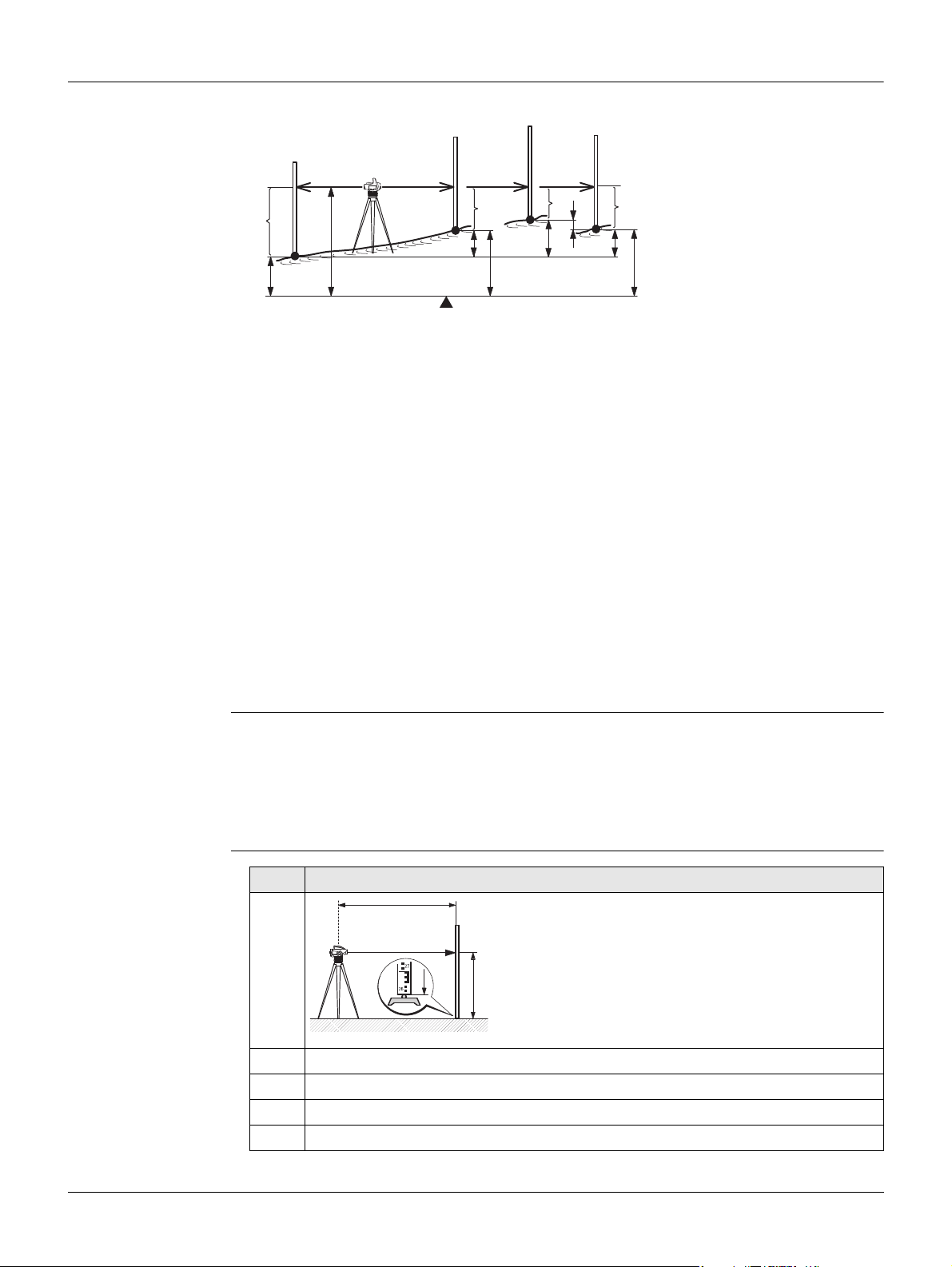
Measurement
Values
B
H
0
007895_001
2
1
STN
D
B
H
Col
D
F
H = 0.0000 m
C
D
INT
F
dH
HH
C
D
INT
Z
INT
d
h
STN Station
1 Staff 1 (backsight staff)
2 Staff 2 (foresight staff)
C
1/C2
Staff C1 and C2 for intermediate or set-out sight
B Staff height backsight. For double observations: B1, B2
F Staff height foresight. For double observations: F1, F2
INT Staff height intermediate sight or set-out sight
D
B
D
F
D
Int
H
0
Backsight distance
Foresight distance
Intermediate sight distance / Set-out distance
Height of starting point, for example, as height above sea level
H Height of foresight point / intermediate point
dH Height difference between backsight and foresight / intermediate sight / set-
out sight
d
h
Sequential height difference between two measurements taken in sequence
(foresight / intermediate sight / set-out sight)
H
Col
Instrument horizon (height of line of sight)
Principle of
Electronic Height
Readings
Electronic Height
Reading with LS10
Instrument
The bar code of the s t a f f is stored i n t he instrument as a reference signal. When measuring, the line decoder captures the visible section of the staff within the field of view
as a measuring signal. The instrument compares the measuring signal to the reference
signal and as a result displays the height of the staff and the horizontal distance.
The sensitivity of the sensor ranges from the highest frequencies of visible light down
to the frequency of infrared light.
Step Description
007890_001
1. Set up the instrument, level it and focus the reticle.
2. Set up staff vertically with the bar code turned toward the instrument.
3. Coarsely aim at staff.
4. Focus with focussing drive.
LS10/LS15, Measurement Guidelines
30
Page 31
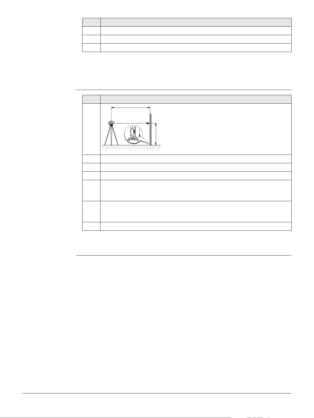
Step Description
5. Fine aim with horizontal drive.
6. Check if the bubble of the circular level is centred.
7. Open a levelling application and press the trigger key to take a measurement.
Electronic Height
Reading with LS15
Instrument
Step Description
1. Set up the instrument, level it and focus the reticle.
2. Set up staff vertically with the bar code turned toward the instrument.
3. Access Q-Level and level the instrument using the electronic level.
4. Switch to the Camera tab. To align the camera crosshair (vertically arranged
5. To focus the staff automatically, either press the softkey Focus or ensure
6. Press the trigger key to take a measurement.
In some cases you may not be able to perform an electronic height reading,
e.g. there are obstacles in the line of sight or there is no overhead clearance
for the staff. In such cases, you can take an optical height reading and add it
to the levelling line. For more details, refer to "5.4 Manual Input Screen for
Optical Height Reading".
007890_001
cursors) in the camera view to the staff, turn the horizontal drive of the
instrument.
that the function AF+Dist+Rec or AF+Dist is assigned to the trigger key (for
more details refer to "6.1 Work Settings").
In case you cannot perform an electronic height reading, you can take an
optical height reading and add it to the levelling line. For more details, refer to
"5.4 Manual Input Screen for Optical Height Reading".
LS10/LS15, Measurement Guidelines
31
Page 32
Angle Measure-
1
2
3
4
5
A
B
007893_001
ment with Digital
Compass (only
LS15)
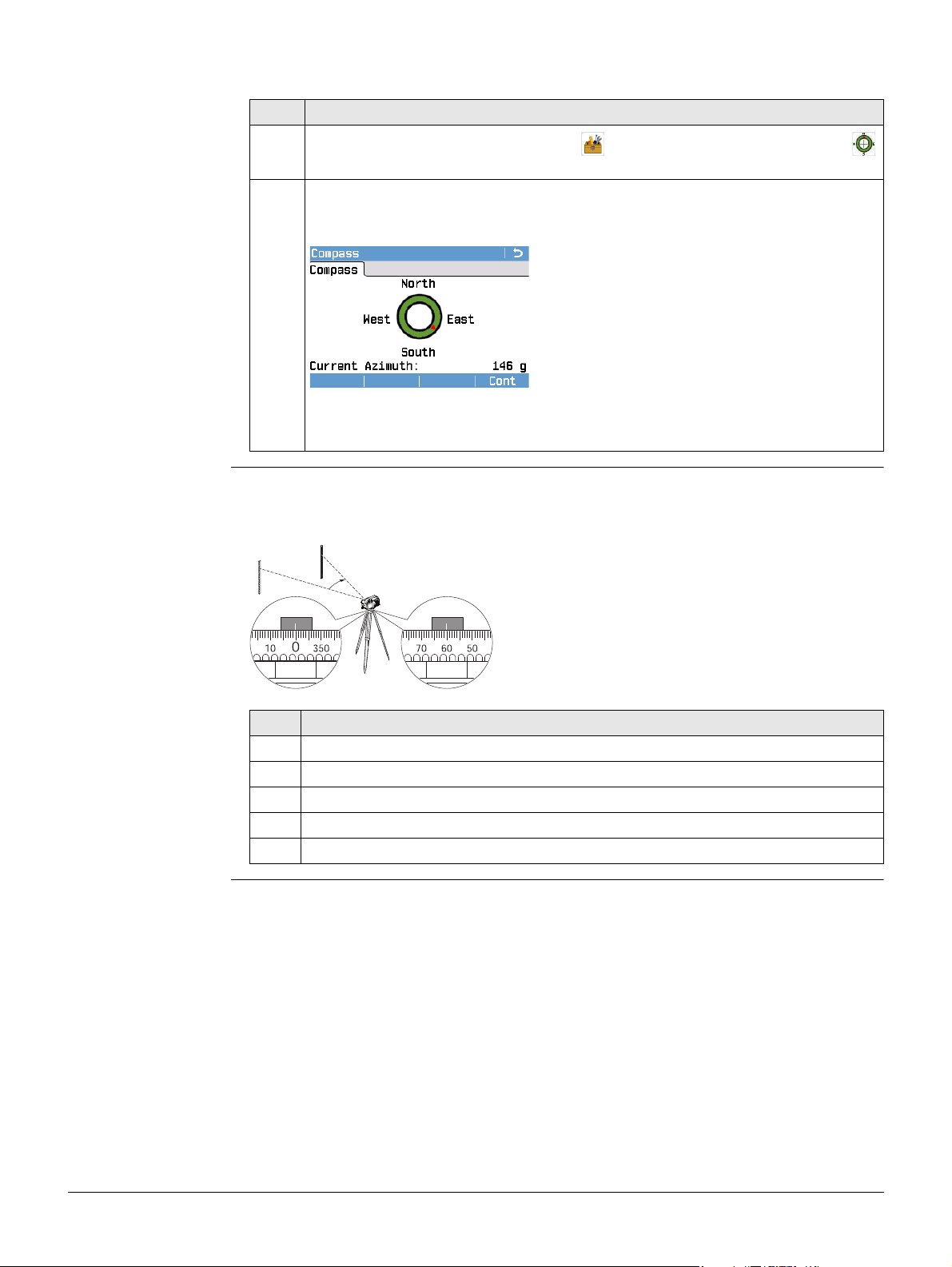
It is recommended to perform a compass calibration before taking an angle
measurement. Refer to "14.6 Calibrating the Digital Compass".
Step Description
1.
To access the digital compass, select Tools from the main menu, then
Compass.
2. Within the Compass screen, the red arrow of the digital compass shows the
current viewing direction of the instrument. In the output field Current
Azimuth, the exact angle in reference to north is displayed.
The LS15 instrument uses the digital compass to calculate the coordinates of
a measured point. Together with the office software Leica Infinity, these
coordinates can be used to visualise the position of a levelling line.
Angle
Measurement with
Horizontal Circle
Both the LS10 and LS15 are equipped with a rotatable horizontal circle. The angle unit
is 360° subdivided into 1° intervals. The gon division is printed in steps of 50 gon
below the 360° division.
Step Description
1. Align instrument to point A.
2. Turn Hz-circle to “0”.
3. Align instrument to point B.
4. Aim on the centre of the staff.
5. Read off Hz-angle from Hz circle. In this example the Hz-angle is 60°.
LS10/LS15, Measurement Guidelines
32
Page 33
5.4 Manual Input Screen for Optical Height Reading
Access
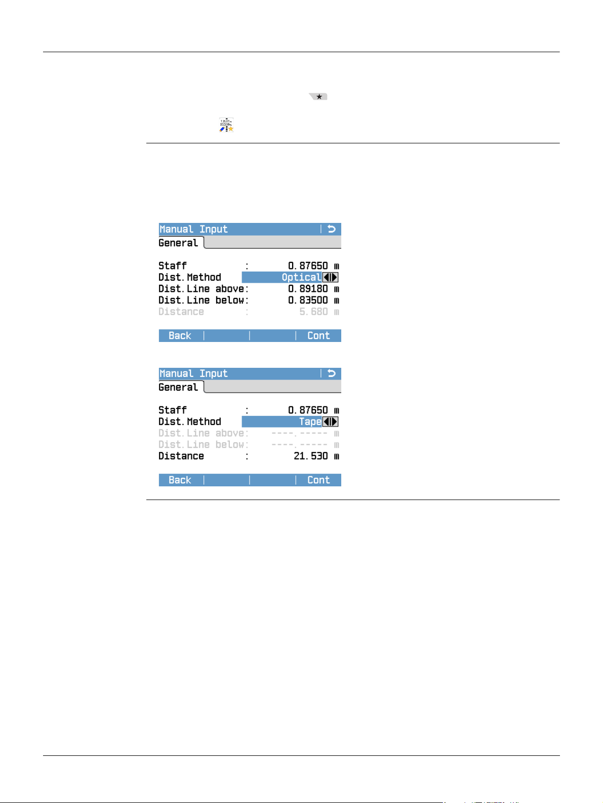
Description If electronic height readings are not possible, you can perform an optical height
1.
2. Change to the Apps tab.
3.
reading and use the Manual Input screen to enter the measured data manually.
With the left and right navigation keys select one of the desired distance methods:
Distance Method Optical
Distance Method Tape
The Manual Input screen can only be accessed from within a levelling application.
Press the Favourites key.
Select Man.Input.
Perform an optical height reading and enter
the values for the staff height and for the
heights of the distance line above and
below. The instrument automatically calculates the distance based on the entered
staff section and the multiplication constant
100.
Press Cont to add the entered data to the
current levelling line.
Perform an optical height reading and
measure the distance with a tape.
Enter the values for the staff height and for
the distance.
Press Cont to add the entered data to the
current levelling line.
LS10/LS15, Measurement Guidelines
33
Page 34

6 Settings
6.1 Work Settings
Access
Work Settings
1.
Select Settings from the Main Menu.
2. Select Work from the Settings Menu.
Field Description
USER Key 1,
USER Key 2
Trigger Key You can assign one of the following functions to the trigger key:
Instr.Start The start screen is displayed after turning on the instrument. You
You can assign one of the following functions to both keys:
• Level: Displays the Level screen.
• Enter Free Code: Displays the Free Code screen from within a
levelling application. Refer to "10 Free Coding".
• Distance Unit: Toggles the displayed distance units ([m], [ft],
[fi]) for all distance and coordinate related fields.
• Home: Displays the Main Menu.
• PIN: Locks the instrument (only if PIN protection is activated).
Refer to "12.4 Instrument Protection with PIN".
• Touch: Activates or deactivates the touchscreen.
• Manual Input: Displays the Manual Input screen.
• PtID Incr: Displays the Point ID & Incrementation screen.
• Screenshot: Captures and saves an image of the currently
displayed screen.
• Next indiv PtID: Applies an individual point ID to the next point
measured. Refer to " Apply an Individual Point ID during measurements".
• Compass: Displays the Compass screen (only LS15).
• Dist: The staff reading and distance are measured.
• Dist+Rec: The staff reading and distance are measured and
stored.
• AF+Dist (only LS15): Focussing is done automatically and the
staff reading and distance are measured.
• AF+Dist+Rec (only LS15): Focussing is done automatically, the
staff reading and distance are measured and stored.
can define one of the following screens as start screen:
• Home (Main Menu)
• Compass Calib (only LS15)
• Level Bubble
• Q-Level
• BasicLevel
• LineLevel
LS10/LS15, Settings
34
Page 35
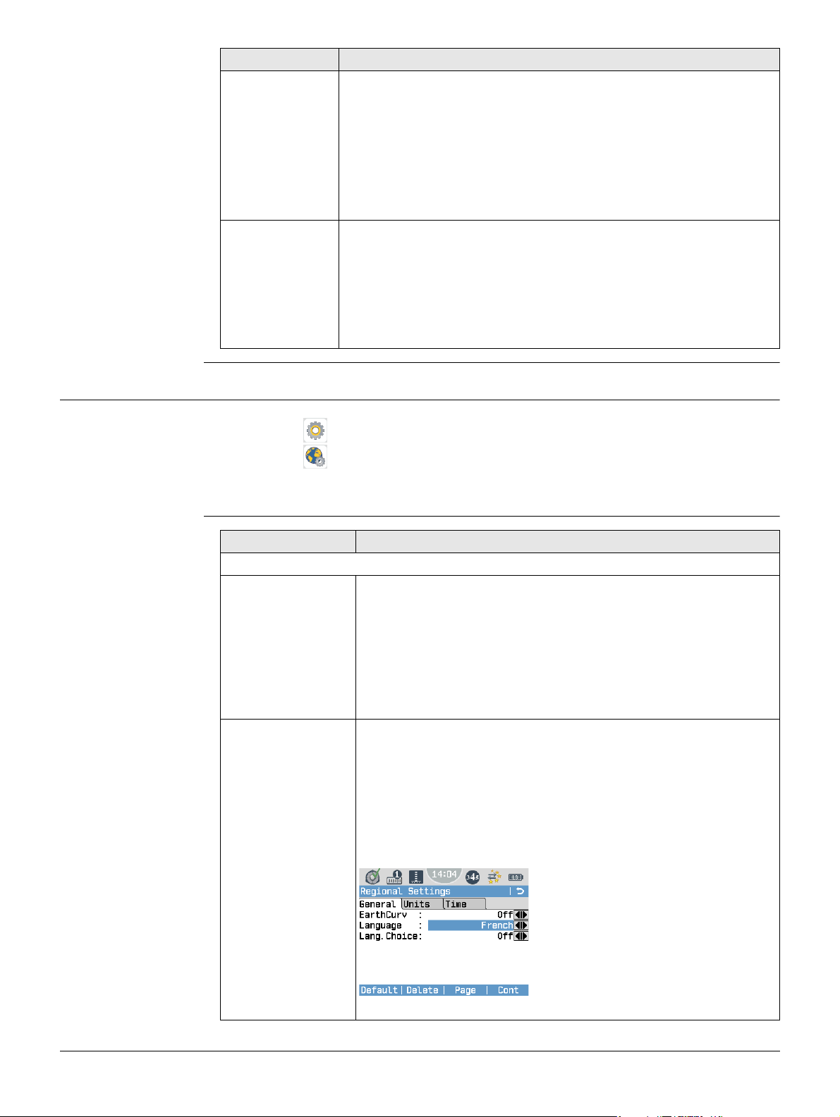
Field Description
Crosshair C.
(only LS15)
Staff Select You can define the staff type used for measurements. Following
You can define one of the following colours for the camera crosshair (vertically arranged indicators):
• Purple
•Blue
• Yellow
•Green
•Black
•Red
options are available:
• Automatic: Select this option for standard measurement tasks.
• Invar 3m: Select this option for high-precision measurements
• Invar 2m: Select this option for high-precision measurements
6.2 Regional Settings
using the GPCL3 Invar staff.
using the GPCL2 Invar staff.
Access
Regional Settings
1. Select Settings from the Main Menu.
2.
Select Regional from the Settings Menu.
3. Press Page (F3) or the Page key to scroll through the screens of available
settings or click directly on the desired tab.
Field Description
Tab General
EarthCurv You can activate or deactivate the earth curvature correction.
If the earth curvature correction is on, electronically measured
or manually entered staff heights are automatically corrected
regarding the curvature of the earth.
Language You can select your preferred language. Several languages can
be uploaded onto the instrument. The current loaded languages
are displayed.
Deleting a language:
If more than one language is installed, you can delete a
language, as long as it is not the chosen operating language. To
delete an inactive language, select the language and press
Delete.
If you start the Check & Adjust application, the earth
curvature correction is automatically set to On. As soon
as you exit the application, the earth curvature correction is set back to the previous setting.
LS10/LS15, Settings
35
Page 36
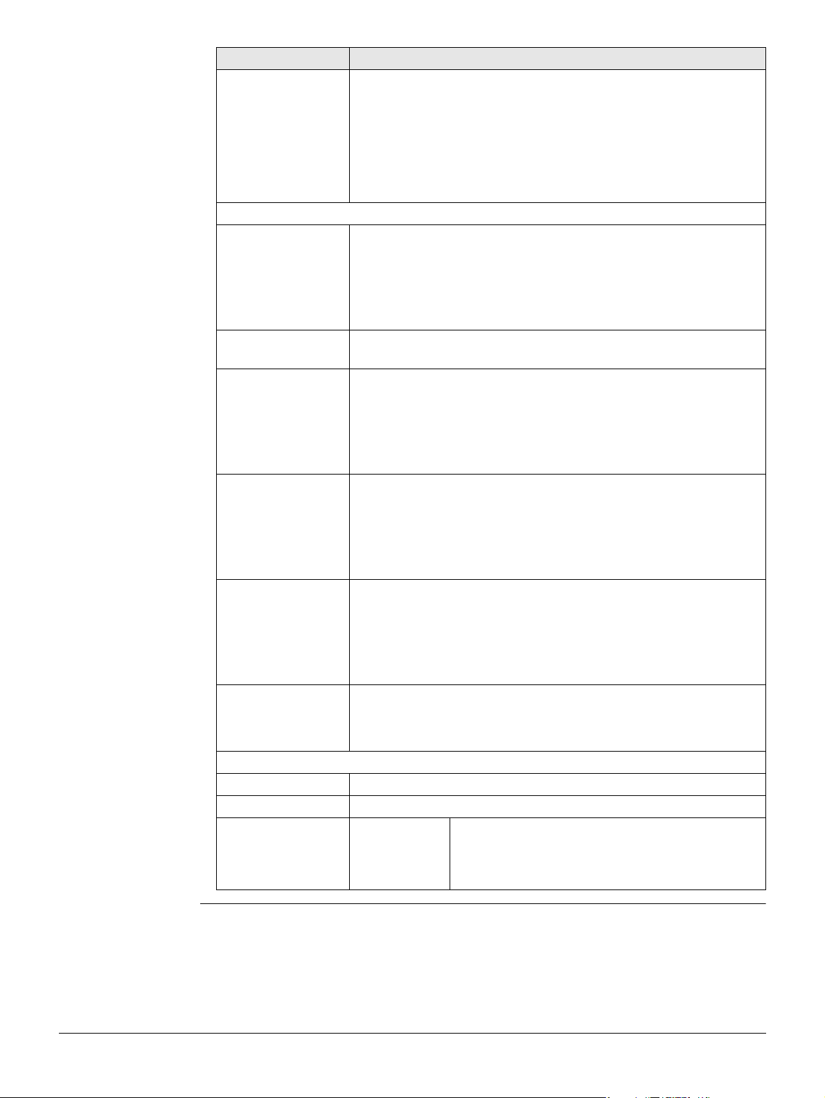
Field Description
Lang.Choice The language screen allows you to choose the language of the
user interface. If you activate the language screen it is displayed
directly after switching on the instrument.
On The language screen is displayed as the startup
screen.
Off The language screen is not displayed as the
startup screen.
Tab Units
Dist. Unit Sets the units shown for all distance and coordinate related
fields.
Meter Meter [m].
US-ft US Survey feet [ft].
INT-ft International feet [fi].
Azimuth Unit Sets the units displayed for all angular fields. You can choose
between gon and dec. deg.
E,N Decimal Sets the number of decimal places displayed for all East and
North coordinates and for all input/output fields.
0 Displays East and North with no decimals.
1 Displays East and North with one decimal.
2 Displays East and North with two decimals.
H Decimal Sets the number of decimal places displayed for all height coor-
dinates and for all input/output fields.
3 Displays height with three decimals.
4 Displays height with four decimals.
5 Displays height with five decimals.
D Decimal Sets the number of decimal places displayed for all distance
input/output fields.
1 Displays distance with one decimal.
2 Displays distance with two decimals.
3 Displays distance with three decimals.
Temp. Unit Sets the units shown for all temperature fields.
°C Degree Celsius.
°F Degree Fahrenheit.
Tab Time
Time (24h) The current time.
Date Shows an example of the selected date format.
Format dd.mm.yyyy,
mm.dd.yyyy
or
yyyy.mm.dd
You can choose between three display formats
for all date-related fields: day-month-year,
month-day-year or year-month-day.
LS10/LS15, Settings
36
Page 37
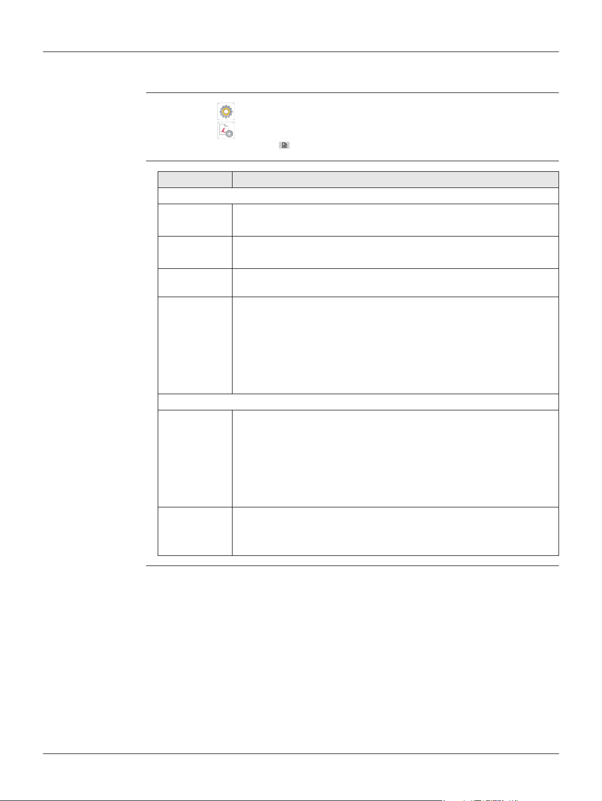
6.3 Data Settings
Description In the Data Settings screen, you can define different options for measurement data,
such as sort order of points within point search or location for data storage.
Access
Data Settings
1. Select Settings from the Main Menu.
2.
Select Data from the Settings Menu.
3.
Press the page key to scroll through the screens of available settings.
Field Description
Record
Sort Type Time Lists are sorted by time of entry.
PtID Lists are sorted by Point IDs.
Sort Order Descending Lists are ordered in descending order of sort type.
Ascending Lists are ordered in ascending order of sort type.
Code Record Defines whether the code block is saved before or after the meas-
urement. Refer to "9 Coding".
Code Defines whether the code is used for one or for many measurements.
Reset after Rec The set code is cleared from the measurement
screen after the measurement has been recorded.
The code is only applied to this single measurement.
Permanent The set code remains in the measurement screen
until you delete it manually. The code is applied to
all further measurements.
Output
Data Output Sets the location for data storage.
Internal
Memory
Interface All recorded data is sent to a connected computer,
GSI-Format Sets the GSI output format.
GSI 8 81..00+12345678
GSI 16 81..00+1234567890123456
All data is recorded in the internal memory.
either through Bluetooth or serial interface. Select
the respective interface in the Interface Settings
screen
LS10/LS15, Settings
37
Page 38
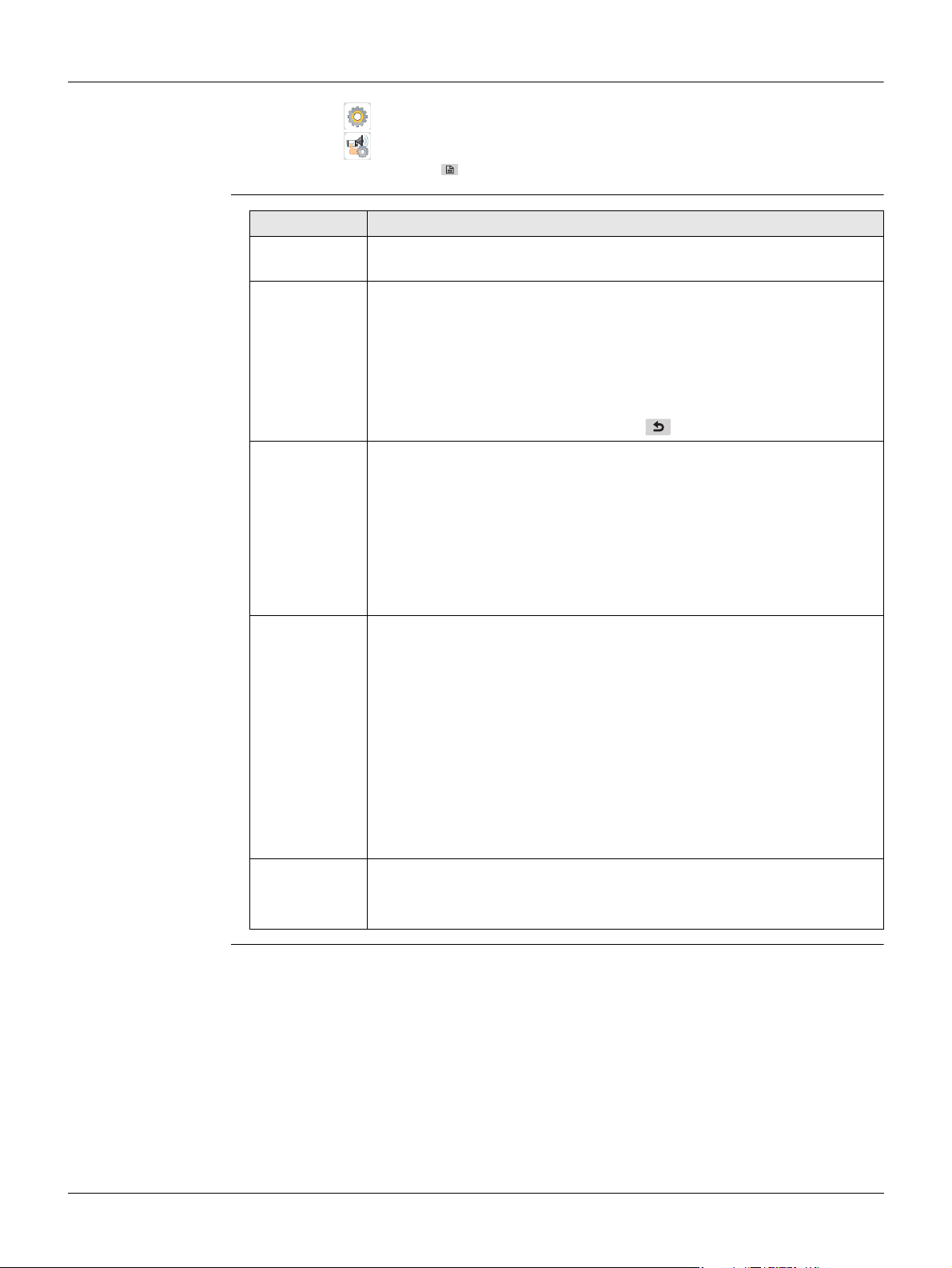
6.4 Screen & Audio Settings
Access
Screen & Audio
Settings
1. Select Settings from the Main Menu.
2.
Select Screen… from the Settings Menu.
3.
Press the page key to scroll through the screens of available settings.
Field Description
Display Ill. 20% to 100% Sets the display illumination in steps of
20%.
Touch Screen On The touchscreen is activated.
Off The touchscreen is deactivated.
Auto-Off Enable The instrument switches off after
Disable The automatic switch-off function is
Standby The instrument switches to standby
Beep The beep is an acoustic signal and is used in the following three vari-
ations:
Single beep: sounds as input confirmation after a key stroke or a
touchscreen event.
Triple beep: sounds when an error message is displayed or when a
function is not allowed.
Long beep: sounds after a measurement has been stored.
You can set the volume of the beep.
Normal Normal volume.
Loud Increased volume.
Off Beep is deactivated.
Screensaver after 1 min, after 2 min,
after 5 min, after 10 min
Off The screensaver is deactivated.
To calibrate the touchscreen, press
Calib.. Follow the instructions on the
screen.
To abort the calibration routine, press the
ESC key.
20 minutes without any activity.
deactivated.
mode after 5 minutes without any
activity.
The screensaver is activated and starts
after the selected time.
Battery discharges quicker.
LS10/LS15, Settings
38
Page 39
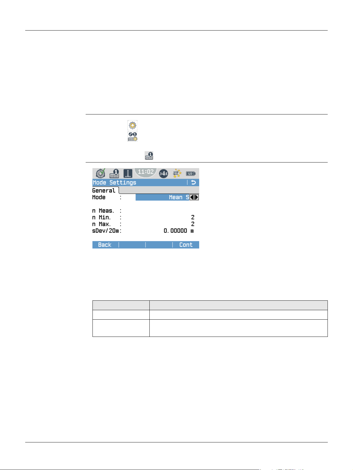
6.5 Mode Settings
Description In the Mode Settings screen you can select different measurement modes for single
or multiple measurements.
Multiple measurements: The instrument automatically carries out several measure-
ments in sequence until one of the following criteria is met:
• The defined number of measurements is reached.
• A terminating criterion is met.
• The procedure is terminated.
For all multiple measurement modes, the instrument stores the average measurement
values according to the mean or median selection and all individual measurements
contributing to this average.
Access
Mode Settings
1. Select Settings from the Main Menu.
2.
Select Mode from the Settings Menu.
To quickly access the Mode Settings screen from within a program, tap on the
status icon .
Mode
To select a mode setting.
n Meas.
Only available for Mean or Median.
To set a number of measurements.
n Min.
Only available for Mean S.
To set a minimum number of measure-
ments.
n Max.
Only available for Mean S.
To set a maximum number of measure-
ments.
sDev/20m
Only available for Mean S.
To set a maximum standard deviation of
the average value at 20 m.
LS10/LS15, Settings
Field Description
Single The instrument carries out a single measurement (n = 1).
Mean Enter the number of measurements to be made (n = 2...99).
The instrument calculates the average of all measurements.
39
Page 40
Field Description
Mean S Enter a minimum and a maximum number of measurements
(n = 2...99) and a maximum standard deviation.
Starting with the minimum number of measurements, the
instrument checks if the measured standard deviation is less or
larger than the entered maximum standard deviation.
• If the deviation is less or equal, the instrument stops measuring.
• If the deviation is larger, the instrument continues measuring
until the maximum number of measurements is reached. At
each step, the instrument checks whether the maximum
standard deviation can be reached by eliminating outliers.
Example:
Measured distance = 60 m, sDevM/20 m = 0.0007 m,
S = sDevM/60 m = 0.0021 m
The maximum allowable standard deviation at 60 m is 0.0021 m.
Median Enter the number of measurements to be made (n = 2...99).
• Uneven number of measurements: The instrument calculates
• Even number of measurements: The instrument calculates
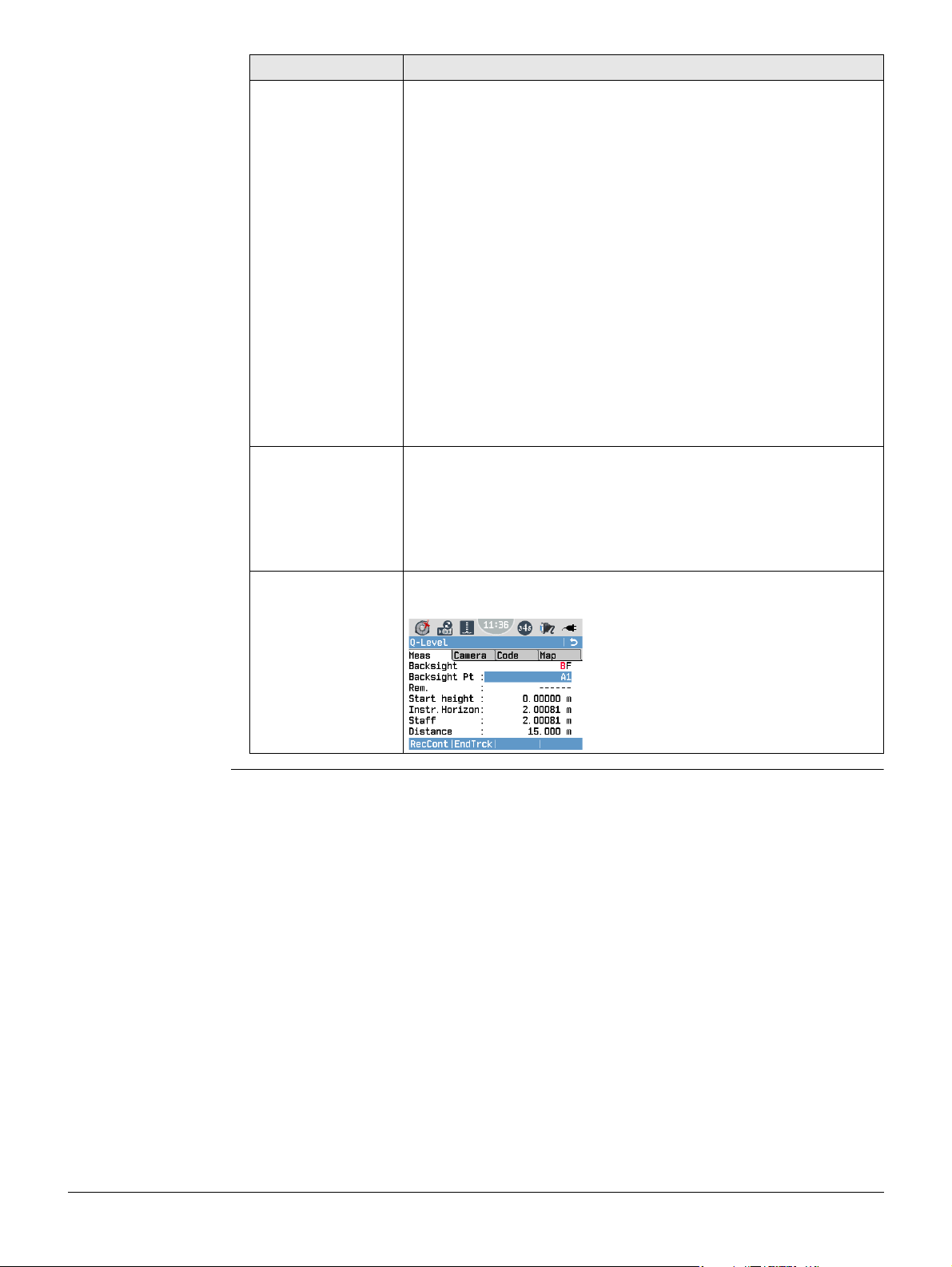
Tracking The instrument continuously takes single measurements until
you end the procedure.
For n Min. = n Max., no measurements are discarded by
the outlier test.
the Median of all measurements by using the central value.
the Median of all measurements by using the two central
values.
Press RecCont to save the last valid
measurement data.
Press EndTrck to stop the measurements without saving data.
LS10/LS15, Settings
40
Page 41
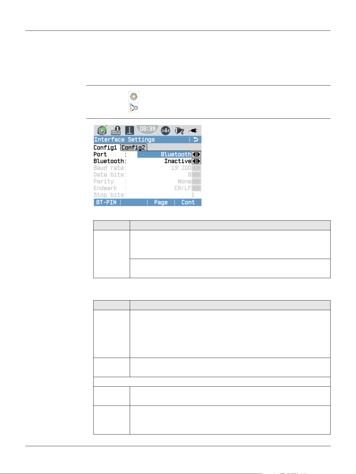
6.6 Interface Settings
Description For data transfer, you need to set the communication parameters of the instrument:
• For serial data communication (e.g. Data import/export, GSI/Geocom commanding),
select either RS232 (only LS15) or Bluetooth.
• For file transfer communication (Active Sync/Mobile Device Centre), select Mini
USB or Lemo USB (only LS15).
For USB connections, serial communication is not supported.
Access
Interface Settings
1. Select Settings from the Main Menu.
2.
Select Interface from the Settings Menu.
BT-PIN
To set a PIN code for the Bluetooth
connection.
Default
For LS10:
Field Description
Port : Instrument port.
Mini USB Communication is via the Mini-USB port.
Bluetooth Communication is via Bluetooth.
Bluetooth: Active Bluetooth sensor is activated.
Inactive Bluetooth sensor is deactivated.
The default Bluetooth PIN is
’0000’.
To reset the fields to the default interface settings. Available, if RS232 is
selected as instrument port.
LS10/LS15, Settings
For LS15:
Field Description
Port : Instrument port.
Mini USB Communication is via the Mini-USB port.
Bluetooth Communication is via Bluetooth.
RS232 Communication is via the serial interface.
Lemo USB Communication is via the Lemo-USB port.
Bluetooth: Active Bluetooth sensor is activated.
Inactive Bluetooth sensor is deactivated.
The following fields are active only when Port : RS232 is set.
Baud rate: Speed of data transfer from receiver to device in bits per second.
1'200, 2'400, 4'800, 9'600, 14'400, 19'200, 38'400, 57'600, 115'200
Data bits: Number of bits in a block of digital data.
7 Data transfer is realised with seven data bits.
8 Data transfer is realised with eight data bits.
41
Page 42
Field Description
Parity : Even Even parity. Available if data bit is set to 7.
Odd Odd parity. Available if data bit is set to 7.
None No parity. Available if data bit is set to 8.
Endmark : CR/LF The terminator is a carriage return followed by a line
feed.
CR The terminator is a carriage return.
Stop bits: 1 Number of bits at the end of a block of digital data.
Acknowlge: On Acknowledgement expected from other device after
data transfer received. If no acknowledgement is
returned, an error message displays.
Off No acknowledgement expected after data transfer.
For Mean, Mean S and Median, you only have to send the
acknowledgement character “?” after the mean/median value is
received, not for the individual measurement generating this
mean/median value.
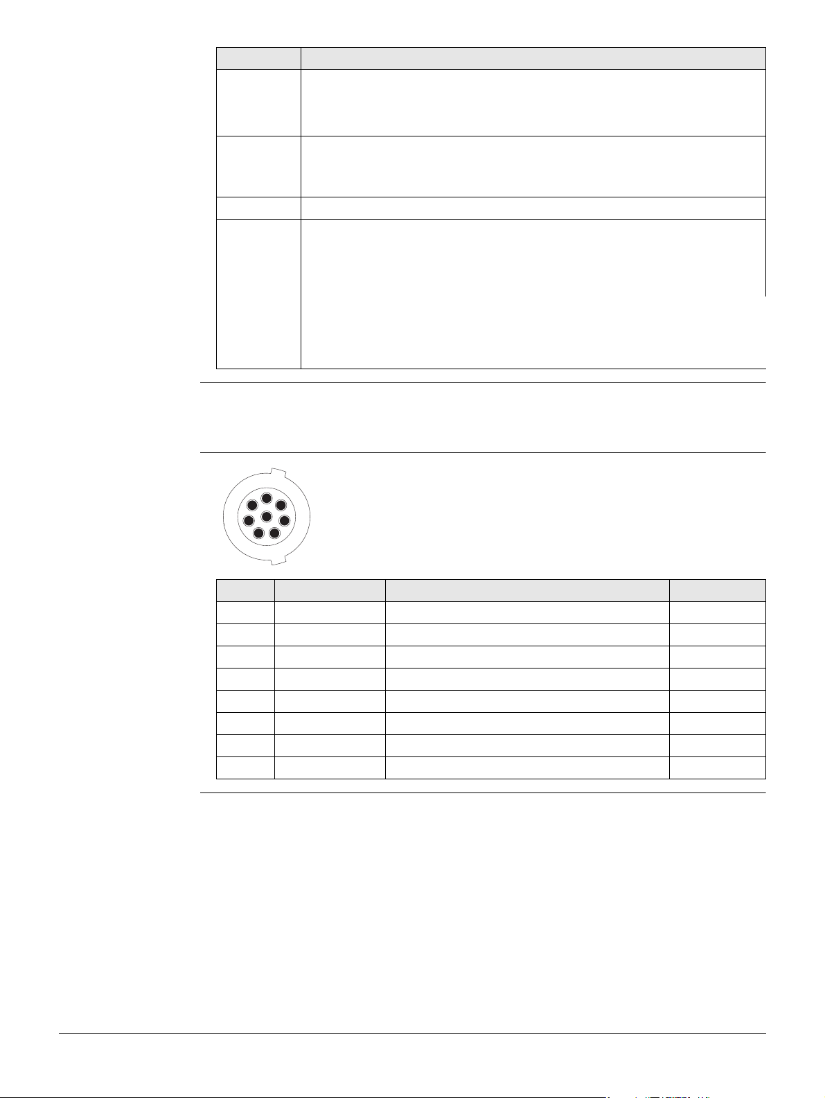
Leica RS232 Default
Settings
Pin Assignments
(only LS15)
When you select Default, the communication parameters are reset to the Leica RS232
default settings:
• 115200 Baud, 8 Databit, No Parity, CR/LF Endmark, 1 Stopbit.
1
7
2
8
6
3
4
5
PIN_001
Pin Signal Name Function Direction
1 USB_D+ USB data line In or out
2 USB_D- USB data line In or out
3 GND Signal ground -
4 RxD RS232, receive data In
5 TxD RS232, transmit data Out
6 ID Identification pin In or out
7 PWR Power input, nominal +12 V (11 V - 16 V) In
8NC Not connected -
LS10/LS15, Settings
42
Page 43
7Programs
7.1 General
7.1.1 Common Fields
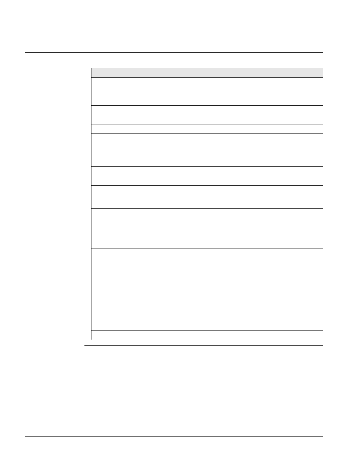
Description of
Fields
The following table describes common fields that are found within the programs.
Field Description
PtID Point ID of the point.
Backsight Pt / PtBS Point ID of backsight point.
Foresight Pt Point ID of foresight point.
Start height / Start H Height of starting point.
Height BS Height of backsight point.
Height FS Height of foresight point.
Total dH Sum of the height differences determined between the
first backsight and the current foresight/backsight observation of this line.
Instr.Horizon Instrument horizon: Height of line of sight.
Staff Height reading on staff.
Distance Distance between instrument and staff
Total Dist Sum of the distances measured between the first back-
sight and the current foresight/backsight observation of
this line.
Dist.Balance Difference between the sum of all foresight distances and
the sum of all backsight distances. For high precision line
levelling, the distance balance at the end of the line should
be close to zero.
Stat.ID ID of current instrument station.
Rem. / Remark / Code Remark (Rem.) or Code name depending on the selected
method.
• Remark: This text is an additional information stored to
the corresponding measurement.
• Code: Within the Code tab, highlight a code from the
code list. The highlighted code is added to the measurement that is stored next. For details on adding or
editing a code refer to "9 Coding".
East Easting coordinate of the point.
North Northing coordinate of the point.
Height Height coordinate of the point.
LS10/LS15, Programs
43
Page 44
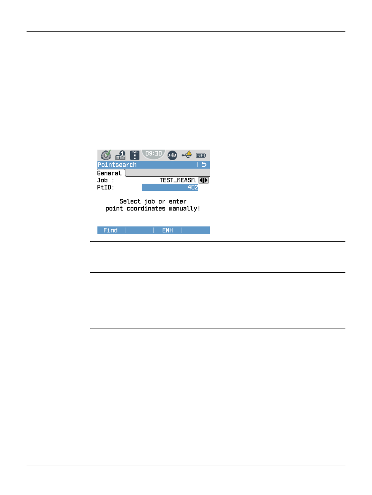
7.1.2 Pointsearch
Description Pointsearch is a function used by programs to find measured points or fixpoints in the
memory storage.
It is possible to limit the point search to a particular job or to search the whole storage.
The search procedure always finds fixpoints before measured points that fulfil the
same search criteria. If several points meet the search criteria, then the results are
ordered according to the entry date. The instrument finds the most recent fixpoint
first.
Direct Search You can search directly for fixpoints by entering a specific point ID:
1) Select a specific job or the option All Jobs.
2) Enter a specific point ID and press the ENTER key.
3) Press Find to start the point search.
All points within the selected job and with the corresponding point ID are found. Use
the Navigation keys to toggle through the found point IDs.
Find
To search for matching points within
the selected job.
ENH
To create a point and enter its coordinates.
Wildcard search The wildcard search is indicated by a "*". The asterisk is a place holder for any
following sequence of characters. Wildcards should be used if the point number is not
fully known, or to search for a batch of points.
Examples of point
searches
* All points are found.
A All points with exactly the point number "A" are found.
A* All points starting with "A" are found, for example, A9, A15, ABCD, A2A.
*1 All points containing only one "1" are found, for example, 1, A1, AB1.
A*1 All points starting with "A" and containing only one "1" are found, for example,
A1, AB1, A51.
LS10/LS15, Programs
44
Page 45
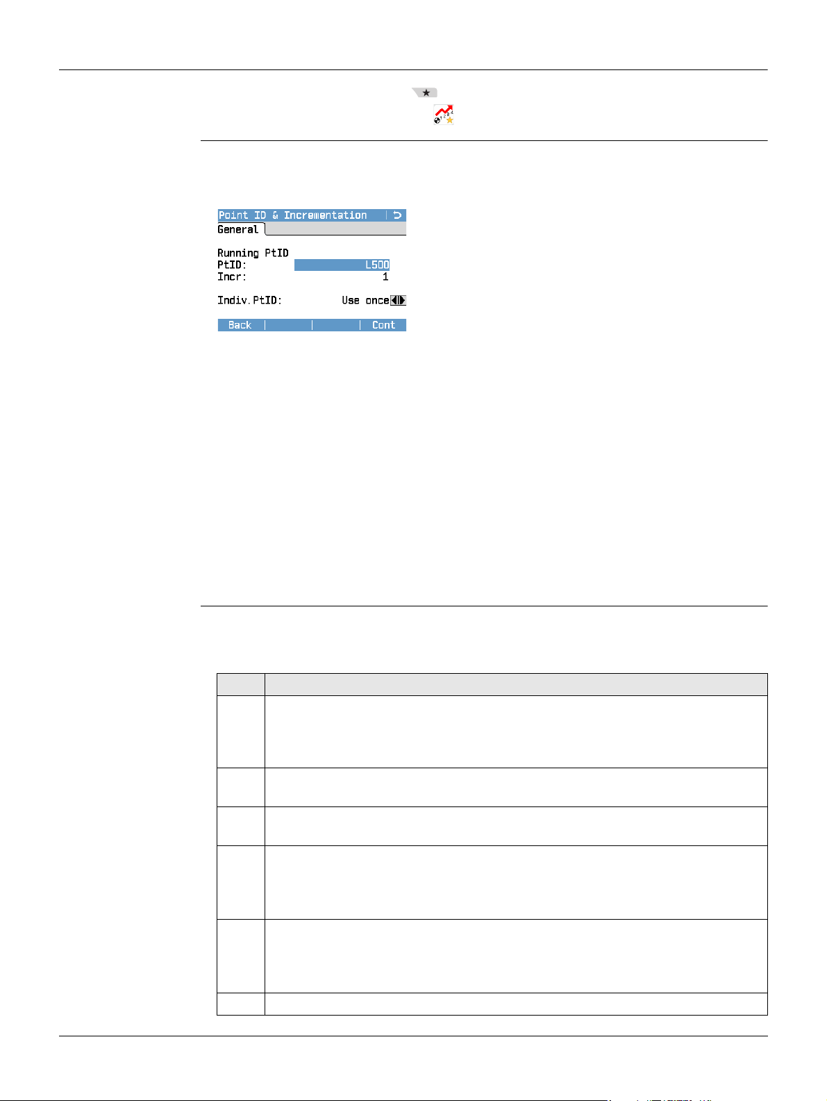
7.1.3 Point ID & Incrementation
Access
Define a Default
Point ID and
Incrementation
1.
Press the Favourites key.
2.
Within the page Setting, tab PtID Incr.
Within the Point ID & Incrementation screen, you can define a default point ID for the
points measured with the levelling applications. You can also define the increment by
which the point IDs are automatically incremented.
PtID: Enter a point ID with 16 characters maximum. The point ID can consist of numeric
and alphanumeric characters. If the point ID ends with an alphanumeric character, the
suffix “01” is added automatically after returning to one of the levelling applications.
Incr: Enter an increment of maximum 9999. This input field is limited to four numeric
characters.
Indiv.PtID: Choose whether the individual point ID is to be applied once or permanently.
• Use once: This is the default value. If selected, the individual point ID is only applied
once to the next point measured. To all following points, the next running point ID
and its defined incrementation are applied.
• Use permanent: If selected, the individual point ID and its defined incrementation
are applied permanently to all following points measured.
The Indiv.PtID: function is also available for surveying intermediate points.
Exception: the point ID of the first intermediate point is always “1001” by
default.
Apply an Individual
Point ID during
measurements
Sometimes it is necessary to measure special points within a line and designate them
with an individual point ID. To avoid retyping and incrementing the point ID manually
for each special point, use the Next indiv PtID function.
Step Description
1. In the Point ID & Incrementation menu, define a default point ID and incre-
mentation to be used for the next measurement task. Make sure that the
function Indiv.PtID: is set to Use once. Refer to "Define a Default Point ID and
Incrementation" (within "7.1.3 Point ID & Incrementation").
2. If not already done, assign the option Next indiv PtID to one of the user keys.
Refer to "6.1 Work Settings".
3. Open a levelling application and start measuring points. The defined default
point ID is applied to the measured points.
4. To apply an individual point ID, enter the desired ID into the Foresight Pt field
before measuring a special point.
The entered point ID is applied to the next point measured. To all following
points, the running point ID is applied again.
5. When measuring another special point, press the respective user key.
The previously entered individual point ID is automatically entered into the
Foresight Pt field and incremented. To all following points, the running point
ID is applied again.
6. Repeat the process as desired.
LS10/LS15, Programs
45
Page 46
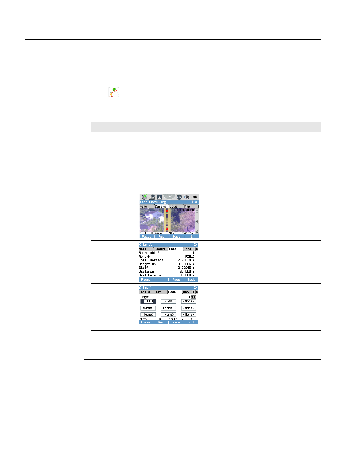
7.2 Q-Level Program
7.2.1 General
Description The Q-Level program allows you to carry out a basic line levelling task using the BF
method. Each time you access Q-Level, a new Line is started and ended when you exit
the application. Use this program, if you immediately want to start measuring after
switching on and setting up the instrument.
Access Select Q-Level from the Main Menu.
You cannot adjust lines that are measured with the Q-Level application.
Available Pages
within the Q-Level
Program
Page Description
Meas This page displays the input/output fields for the current measure-
Camera (only
LS15)
Last
Use the Page key or the softkey Page (F3) to toggle between the different
pages.
ment. For more details refer to "7.2.2 Measurement Procedure for
Q-Level".
This page displays the live image of the overview camera. Use the
Camera page to quickly aim at the staff.
The selected levelling method is displayed in the upper right-hand
corner with the current measurement step (backsight or foresight)
highlighted red.
This page is only available after the first
measurement has been stored. The values
of the last measurement are displayed.
LS10/LS15, Programs
Code
Map (only LS15) This page displays a graphical overview over the last five instrument
stations and the related measurements. For more details refer to
"11 MapView".
This page contains a list of codes.
Highlight a code to add it to the next measurement. Press Edit to edit the selected
code in the Manage Codes screen. For
more details on managing codes, refer to "9
Coding".
46
Page 47
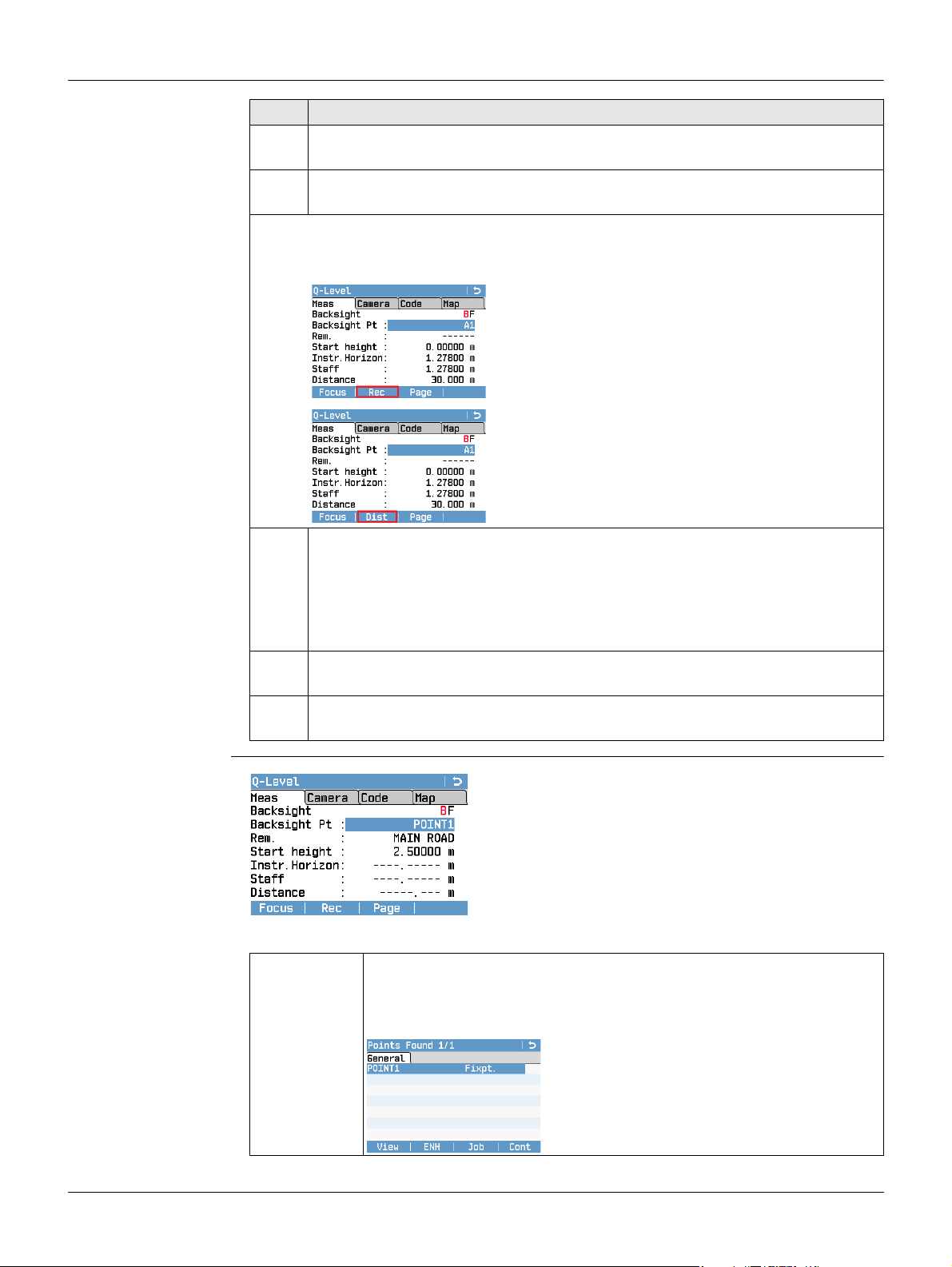
7.2.2 Measurement Procedure for Q-Level
Measurement
Procedure
Step Description
1. Enter the height of the starting point manually or search for an already stored
2. Measure the first backsight: Aim at the staff and press the trigger key.
3. After storing the measurement of the first backsight, the foresight screen is
4. Measure the foresight. The procedure for aiming and measuring is the same
5. After storing the measurement of the foresight, the next backsight screen is
The first screen allows you to measure the first backsight, which is the
starting point of the line.
fixpoint or adjusted point in the current job.
Depending on the setting of the trigger key, the measurement is executed
with or without storing the measured values.
Backsight/Foresight: The current viewing direction
is highlighted in red.
If the trigger key is set to Dist or AF+Dist (only
LS15), press Rec (F2 softkey) to store the measurement.
If the trigger key is set to Dist+Rec or AF+Dist+Rec
(only LS15), press Dist (F2 softkey) to take a measurement without storing it; e.g. in order to verify the
correct distance of a foresight staff before the
actual measurement.
displayed. Before measuring a foresight, you can measure intermediate
points or set out heights, height differences and distances.
as described for the first backsight.
displayed. You can continue to measure backsight and foresight points.
You can define an individual point ID for the next point measured.
Refer to "Apply an Individual Point ID during measurements" (within
"7.1.3 Point ID & Incrementation").
Starting Screen
(First Backsight)
LS10/LS15, Programs
Focus
To automatically focus the telescope
(only LS15).
Rec
To save the measured values and
switch to the foresight screen.
Before measuring the first backsight point, you can edit the following fields:
Backsight Pt ID of the starting point (first backsight). Default value is “A1”.
To search for fixpoints, enter a start point ID and confirm with the
ENTER key. For more details on pointsearch refer to "7.1.2
Pointsearch".
If one or more fixpoints with this ID are
already stored in the current job, all available
fixpoints are displayed in the Points Found
screen. Select the desired fixpoint and press
Cont to return to the first backsight screen.
47
Page 48
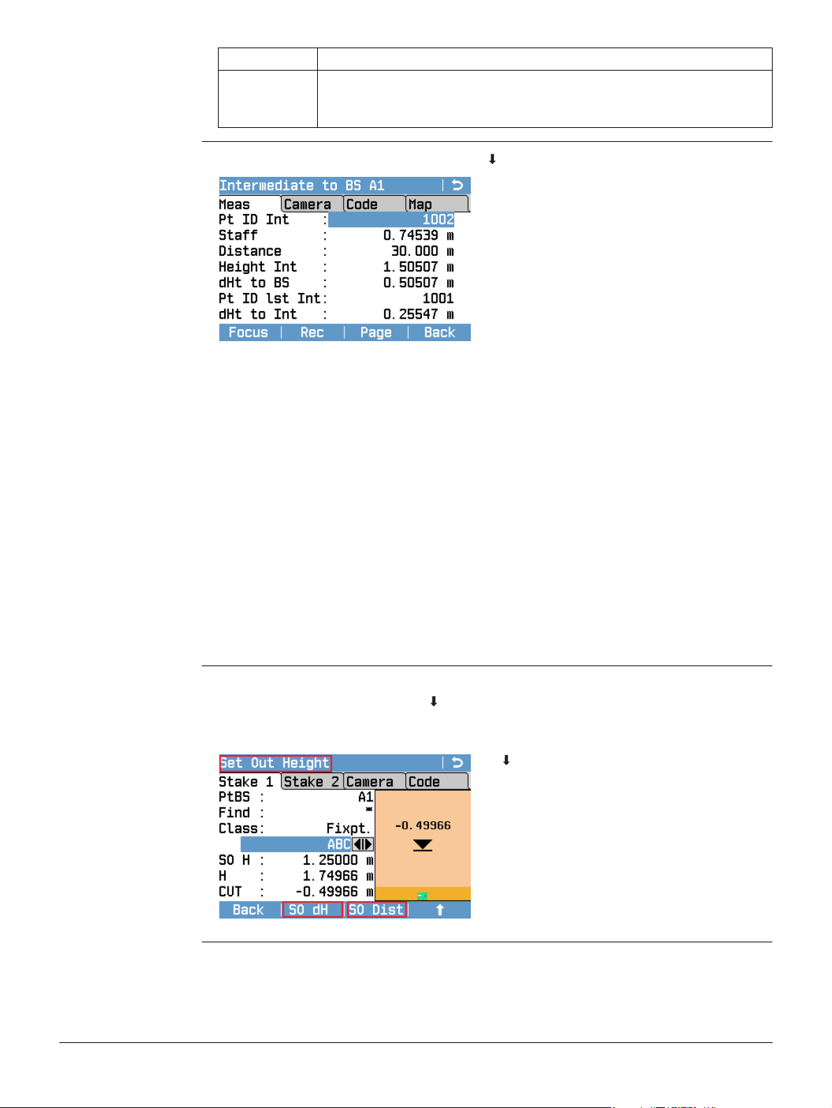
Rem. Additional Remarks concerning the measurement (optional).
Start height Height of the starting point. Default value is 0.00000 m.
If you select an already stored fixpoint as starting point, the field Start
height is automatically set to the height of the fixpoint.
Survey Intermediate Points
To switch to the INT to BS display, press and the INT softkey.
Back
To exit INT to BS and return to the
foresight/backsight display.
Before taking a measurement:
Pt ID Int You can enter the point ID of the intermediate point.
Default value is 1001. The point ID is incremented after
each measurement.
After taking a measurement:
Staff The staff reading of the currently measured point.
Distance The distance between the instrument and the interme-
diate point.
Height Int The height of the currently measured intermediate point.
dHt to BS The height difference between the currently measured
point and the last backsight point.
Pt ID lst Int The point ID of the last intermediate point. When meas-
uring the first intermediate point, this field remains
empty.
dHt to Int The height difference between the last intermediate
point and the currently measured intermediate point.
When measuring the first intermediate point, this field
remains empty.
SetOut Application With the SetOut application, you can set out heights, height differences or distances.
To access the application, press and the SetOut softkey.
The Set Out Height screen is displayed first. From this screen, you can access the
screens for setting out height differences or distances.
Softkey
To display further softkeys.
SO dH
To display the Set Out dH screen.
SO Dist
To display the Set Out Distance
screen.
Back
To exit SetOut and return to the fore-
sight/backsight display.
LS10/LS15, Programs
48
Page 49
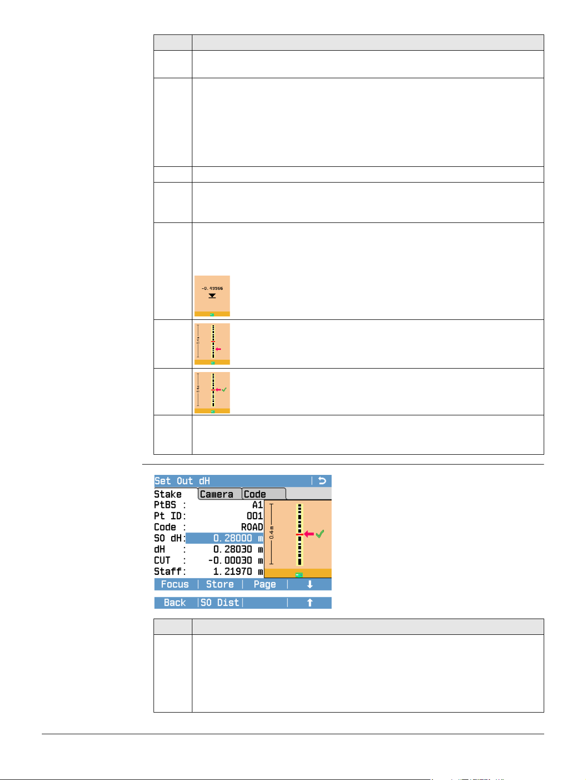
Set Out Heights
Step-by-Step
Step Description
1. To load a fixpoint, enter the ID of the point in the field Find and press the
2. Press the trigger key to take a measurement.
3. Display field H: Measured height value.
Before you set out height values, ensure that these heights are stored as
fixpoints in the current job.
ENTER key. Select the desired fixpoint from the list and press Cont. You can
also use the left and right navigation keys to toggle through the list of available points.
Class: Displays the type of the selected point (AdjPt., Fixpt., Meas.).
SO H: Height value of the selected fixpoint. This value is used as the set-out
height.
Depending on the difference between set-out height and measured height,
the following fields and graphical elements are displayed:
FILL :: Difference between measured height and set-out height (positive
value). The staff is too low.
CUT :: Difference between measured height and set-out height (negative
value). The staff is too high.
When the difference is greater than 0.2 m, a black arrow indicates
whether the measured height is above or below the set-out height.
Set Out Height
Differences Stepby-Step
When the difference is less than 0.2 m, a red arrow indicates
whether the measured height is above or below the set-out height.
When the difference is less than 0.01 m, a green checkmark is
displayed.
4. Raise or lower the staff according to the displayed value and take a new
measurement. Repeat this step until the measured height corresponds to
the set-out height.
Back
To exit Set Out dH and return to the Set
Out Height screen.
SO Dist
To display the Set Out Distance screen.
LS10/LS15, Programs
Step Description
1. Enter the necessary data.
Pt ID: If desired, you can change the point ID. Default value is 1001. The
point ID is incremented after each measurement.
Rem.: If desired, enter a remark. When you enter a code, the field name
changes to Code.
SO dH: Enter the height difference that needs to be set out.
49
Page 50
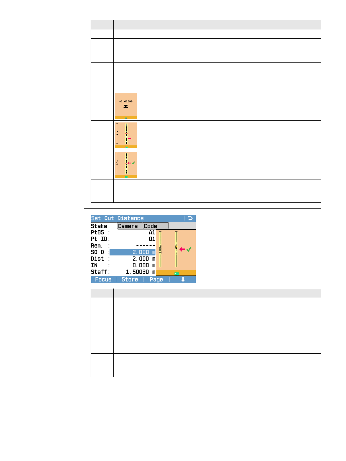
Step Description
2. Press the trigger key to take a measurement.
3. Display field dH: Measured height difference.
Depending on the difference between entered and measured height difference, the following fields and graphical elements are displayed:
FILL :: Difference from entered height difference (positive value). The staff
is too low.
CUT :: Difference from entered height difference (negative value). The staff
is too high.
When the difference is greater than 0.2 m, a black arrow indicates
whether the measured height difference is above or below the
entered value.
When the difference is less than 0.2 m, a red arrow indicates
whether the measured height difference is above or below the
entered value.
When the difference is less than 0.01 m, a green checkmark is
displayed.
4. Raise or lower the staff according to the displayed value and take a new
measurement. Repeat this step until the measured height difference corresponds to the entered height difference.
Set Out Distances
Step-by-Step
Back
To exit Set Out dH and return to the Set
Out Height screen.
SO dH
To display the Set Out dH screen.
Step Description
1. Enter the necessary data.
Pt ID: If desired, you can change the point ID. Default value is 1001. The
point ID is incremented after each measurement.
Rem.: If desired, enter a remark. When you enter a code, the field name
changes to Code.
SO D: Enter the distance that needs to be set out.
2. Press the trigger key to take a measurement.
3. Display field Dist: Measured distance.
Depending on the difference between entered and measured distance, the
following fields and graphical elements are displayed:
LS10/LS15, Programs
50
Page 51
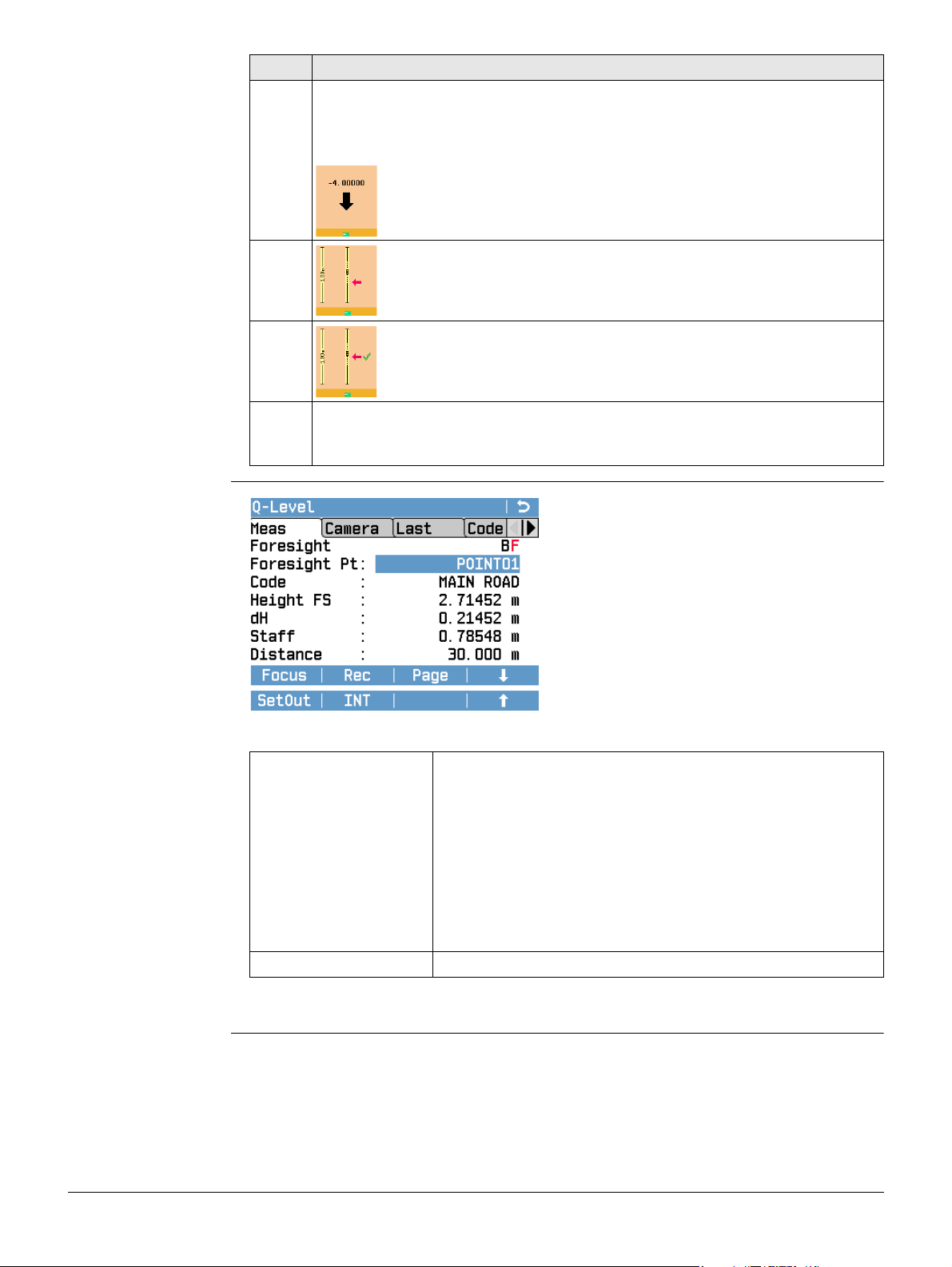
Step Description
OUT :: Difference from entered distance (positive value). The distance
between instrument and staff is too small.
IN :: Difference from entered distance (negative value). The distance
between instrument and staff is too big.
When the difference is greater than 0.5 m, a black arrow indicates
whether the measured distance is too small or too big.
When the difference is less than 0.5 m, a red arrow indicates
whether the measured distance is smaller or greater than the
entered value.
When the difference is less than 0.03 m, a green checkmark is
displayed.
4. Move the staff according to the displayed value and take a new measure-
ment. Repeat this step until the measured distance corresponds to the
entered distance.
Foresight Display
Focus
To automatically focus the telescope
(only LS15).
Rec
To save the measured values and
switch to the backsight screen.
SetOut
To switch to the Set Out Height
screen.
INT
To survey intermediate points.
Before measuring the foresight point, you can edit the following fields:
Foresight Pt The default value is 1. You can enter a point ID or change the
default value in the Point ID & Incrementation screen. The
ID of the foresight point is incremented automatically
according to the definitions of the Point ID & Incrementa-
tion screen (refer to " Define a Default Point ID and Incrementation").
Rem. Additional Remarks concerning the measurement (optional).
You can define an individual point ID for the next
point measured. Refer to "Apply an Individual Point
ID during measurements" (within "7.1.3 Point ID &
Incrementation").
LS10/LS15, Programs
Press the trigger key to measure the foresight point. The measured values are
displayed in the fields Height FS, dH, Staff and Distance.
51
Page 52
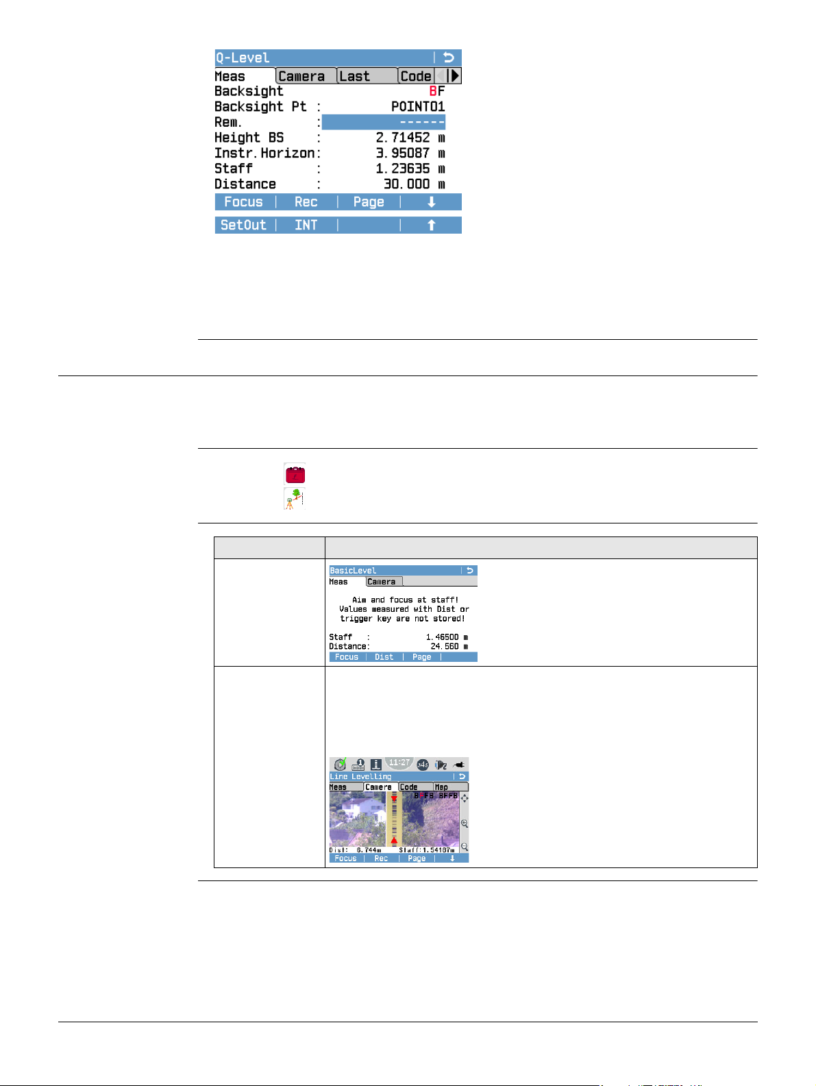
Backsight Display
Before measuring the backsight point, you can edit the field Rem. to enter a remark
concerning the measurement.
Press the trigger key to measure the backsight point. The measured values are
displayed in the fields Instr.Horizon, Staff and Distance.
Focus
To automatically focus the telescope
(only LS15).
Rec
To save the measured values and
switch to the foresight screen.
SetOut
To switch to the Set Out Height
screen.
INT
To survey intermediate points.
7.3 BasicLevel Program
Description The BasicLevel program allows you to take an unlimited number of single or multiple
measurements without storing the data. The program is intended for general levelling
purposes.
Access
Available Pages
within the Basi-
cLevel Program
1. Select Programs from the Main Menu.
2.
Select BasicLevel from the Programs Menu.
Page Description
Meas
Camera (only
LS15)
This page displays the live image of the overview camera. Use the
Camera page to quickly aim at the staff.
The selected levelling method is displayed in the upper right-hand
corner with the current measurement step (backsight or foresight)
highlighted red.
This page displays the output fields for the
current measurement.
To take a measurement, tap Dist or press
the trigger key.
LS10/LS15, Programs
52
Page 53
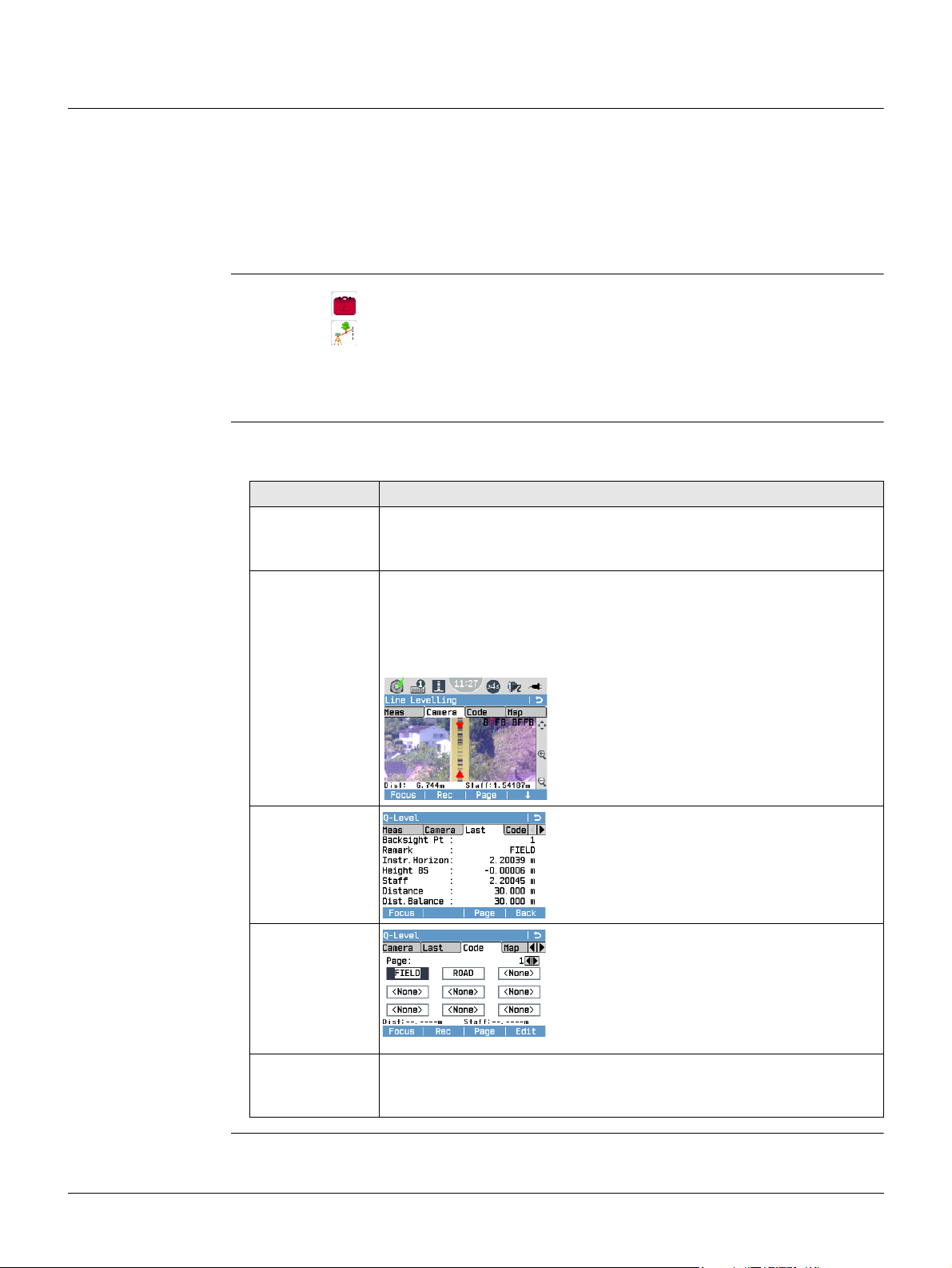
7.4 LineLevel Program
7.4.1 General
Description The LineLevel program allows you to make detailed preferences before carrying out
a line levelling task:
•Setting a job
• Setting tolerances
• Setting a line and a measurement method
Lines measured within the LineLevel program can be adjusted later on with the inte-
grated LineAdjust program.
Access
Available Pages
within the LineLevel
Program
1. Select Programs from the Main Menu.
2.
Select LineLevel from the Programs Menu.
3. • To set a job, press F1.
• To set tolerances, press F2.
• To set a line and a method and start the levelling, press F4.
Page Description
Meas This page displays the input/output fields for the current measure-
Camera
(only LS15)
Use the Page key or the softkey Page (F3) to toggle between the different
pages.
ment. For more details refer to "7.4.5 Measurement Procedure for
LineLevel".
This page displays the live image of the overview camera. Use the
Camera page to quickly aim at the staff.
The selected levelling method is displayed in the upper right-hand
corner with the current measurement step (backsight or foresight)
highlighted red.
LS10/LS15, Programs
Last
Code
Map (only LS15) This page displays a graphical overview over the last five instrument
stations and the related measurements. For more details refer to
"11 MapView".
This page is only available after the first
measurement has been stored. The values
of the last measurement are displayed.
This page contains a list of codes.
Highlight a code to add it to the next meas-
urement. Press Edit to edit the selected
code in the Manage Codes screen. For
more details on managing codes, refer to "9
Coding".
53
Page 54
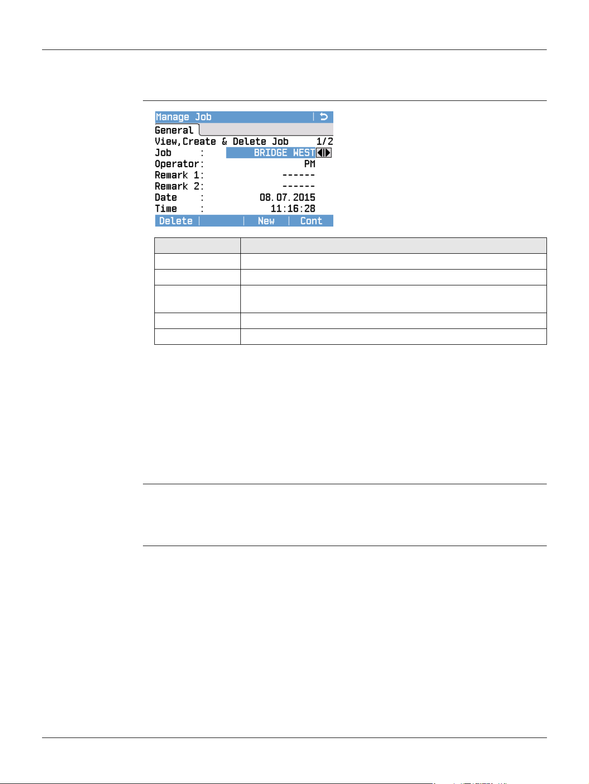
7.4.2 Setting a Job
Description All data is saved in Jobs, like file directories. Jobs contain measurement data of
different types, for example measurements, codes, fixpoints or stations. Jobs are individually manageable and can be exported, edited or deleted separately.
Select Job
Delete
To delete an existing job.
New
To create a job.
Field Description
Job Name of an existing job.
Operator Name of operator (optional).
Remark 1,
Remark 2
Date Date on which the selected job was created.
Time Time at which the selected job was created.
How to Set an Existing Job
• Use the navigation keys to select an existing job.
• To continue with the selected job, press Cont.
How to Create and Set a New Job
• Press New to open the Enter Job Data screen.
• Enter the required job data.
• To return without saving the entered data, press Back.
• To save the entered job data and return to the previous screen, press Cont.
• To continue with the created job, press Cont.
Once you saved the entered job data, you cannot change it anymore.
Additional remarks (optional).
Recorded Data Once a job is set up, all subsequent recorded data will be stored in this job.
LS10/LS15, Programs
If no job is defined and you start a program, or if you record a measurement
within Q-Level, the system automatically creates a new job and names it
"Default".
54
Page 55
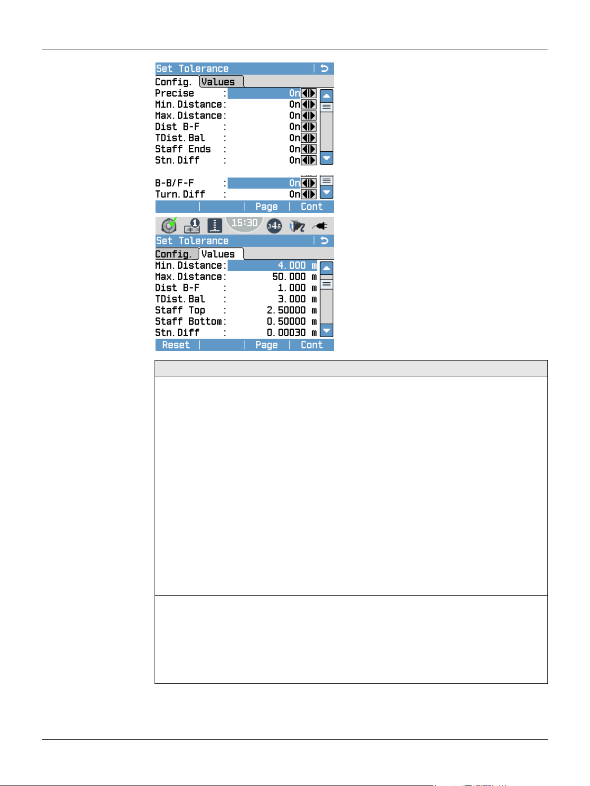
7.4.3 Setting Tolerances
Set Tolerance
Reset
To select an item of the list and to
activate or deactivate the selected
item, use the navigation keys.
To reset tolerances to default values.
Field Description
Precise : When taking measurements near the edge of the staff, the
reduced number of staff code elements may slightly lower the
measuring accuracy.
If Precise : is activated, the instrument monitors whether the
height reading is within 0.50 m to either end of the staff (top and
bottom). The top and bottom limits of the staff are automatically
converted to a 3 m Invar staff. In order to use different staff
lengths, you can manually adjust the limit values.
The precision mode also monitors critical distances between the
instrument and the staff. These distances depend on the physical
properties of the staff code. The measuring accuracy of height
measurements within these distance ranges may also be slightly
lower. A warning is displayed if the measuring distance is within
the following ranges: 13.250 m - 13.500 m and 26.650 m -
26.900 m. If the instrument detects a staff distance within these
ranges, slightly move the staff out of the mentioned measurement range in order to maintain highest measurement accuracy
expectations.
Min.Distance: If activated, the instrument monitors the minimum target
distance. If the tolerance is exceeded, a warning message is
displayed. For a detailed description of the warning message,
refer to the next paragraph " Warning Message “Tolerance
exceeded!”".
Change to the Values screen, to enter a value for the minimum
target distance.
LS10/LS15, Programs
55
Page 56

Field Description
Max.Distance: If activated, the instrument monitors the maximum target
distance. If the tolerance is exceeded, a warning message is
displayed. For a detailed description of the warning message,
refer to the next paragraph " Warning Message “Tolerance
exceeded!”".
Change to the Values screen, to enter a value for the maximum
target distance.
Dist B-F : Only available for double observation levelling methods such as
BFFB. If activated, the instrument monitors the distance balance
between foresight and backsight distance on the current station.
If the tolerance is exceeded, a warning message is displayed. For
a detailed description of the warning message, refer to the next
paragraph " Warning Message “Tolerance exceeded!”".
Change to the Values screen, to enter a value for the distance
balance.
TDist.Bal : If activated, the instrument monitors the total distance balance
between foresight and backsight distances. If the tolerance is
exceeded, a warning message is displayed. For a detailed description of the warning message, refer to the next paragraph "
Warning Message “Tolerance exceeded!”".
Change to the Values screen, to enter a value for the distance
balance.
Staff Ends : If activated, the instrument monitors whether a measurement is
within the staff end zones. If the tolerance is exceeded, a warning
message is displayed. For a detailed description of the warning
message, refer to the next paragraph " Warning Message “Tolerance exceeded!”".
Change to the Values screen, to enter values for Staff Top and
Staff Bottom.
Stn.Diff : If activated, the instrument monitors the permitted station differ-
ence. If the tolerance is exceeded, a warning message is
displayed. For a detailed description of the warning message,
refer to the next paragraph " Warning Message “Tolerance
exceeded!”".
Change to the Values screen, to enter a value for the station
difference.
B-B/F-F : If activated, the instrument monitors the permitted maximum
difference of double observations. If the tolerance is exceeded, a
warning message is displayed. For a detailed description of the
warning message, refer to the next paragraph " Warning Message
“Tolerance exceeded!”".
Change to the Values screen, to enter a value for the maximum
difference.
Turn.Diff : Only available for the levelling methods SimBF and SimBFFB. If
activated, the instrument monitors whether the height difference
of the two ground points of the staffs is identical for station n in
the foresight measurement and for station n+1 in the backsight
measurements. If the tolerance is exceeded, a warning message is
displayed. For a detailed description of the warning message,
refer to the next paragraph " Warning Message “Tolerance
exceeded!”".
LS10/LS15, Programs
56
Page 57
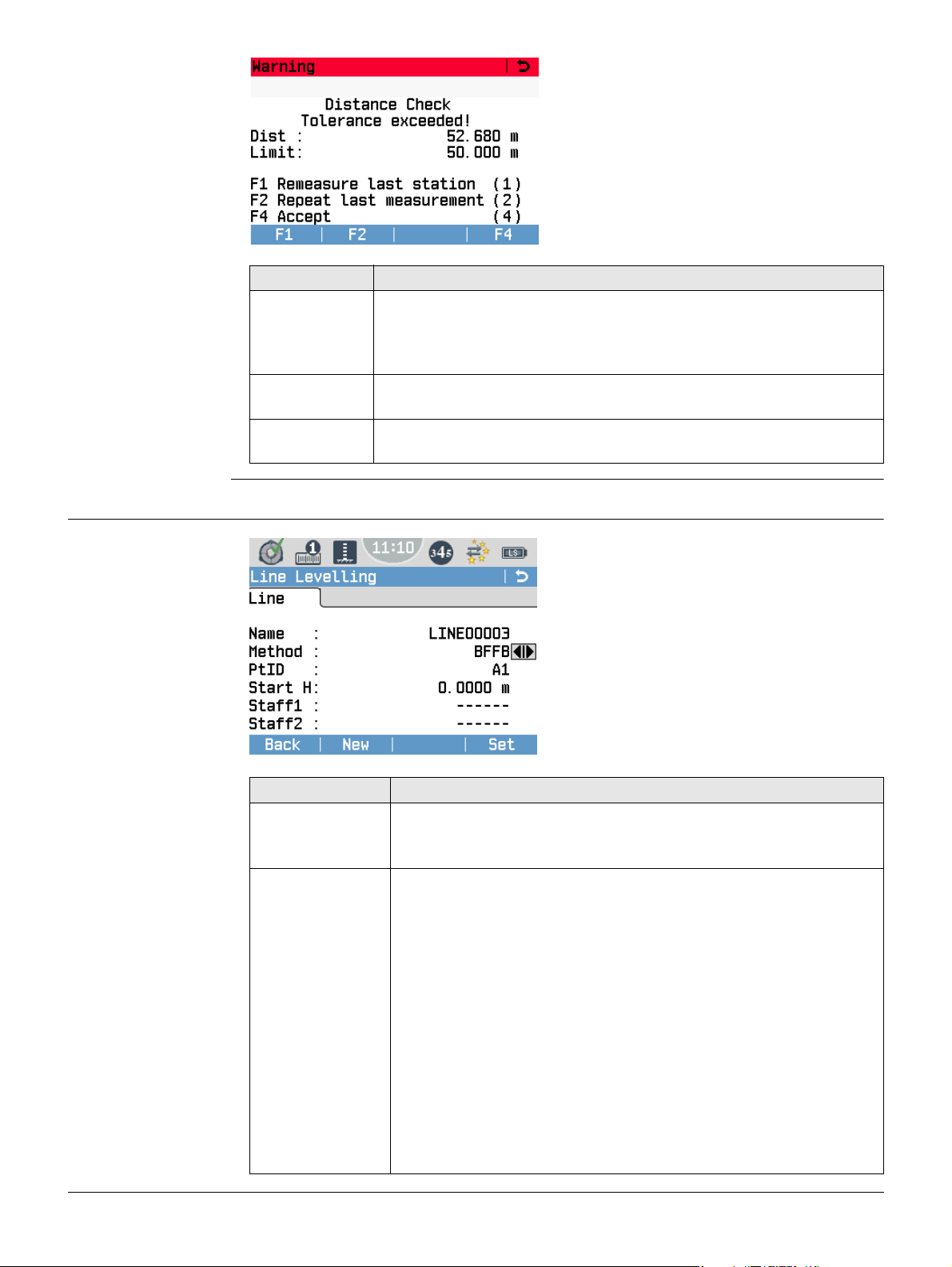
Warning Message
“Tolerance
exceeded!”
Option Description
F1 If you select F1 Remeasure last station (1), the instrument assumes
that all staff ground points are clearly identified and unchanged. All
prior measurements for this station are deleted and have to be
remeasured.
F2 If you select F2 Repeat last measurement (2), only the last measure-
ment for this station is deleted and has to be remeasured.
F4 If you select F4 Accept (4), the instrument ignores the warning
message and stores the measurement.
7.4.4 Setting a Line and a Method
Example of warning message screen. The
title of the screen describes which type
of tolerance has been exceeded, e.g. the
distance tolerance.
Line
New or List
New: To create a line. Only available if
the job already contains one or more
lines.
List: To view a list of available points
within the job. Only available if you
create a line or if the job contains no
line at all.
Set
To set the selected line and method
and continue with the program.
Field Description
Name Name of the current line.
If the job is empty, a new line name is automatically created and
displayed.
Method Select a levelling method:
• BF: Backsight and foresight are measured according to the
pattern BF BF.
• BFFB: Backsight and foresight are measured according to the
pattern BFFB BFFB.
• BBFF: Backsight and foresight are measured according to the
pattern BBFF BBFF.
• BFBF: Backsight and foresight are measured according to the
pattern BFBF BFBF.
• aBF: Backsight and foresight are measured alternatingly
according to the pattern BF FB BF FB.
• aBFFB: Backsight and foresight are measured alternatingly
according to the pattern BFFB FBBF BFFB.
• aFBBF: Backsight and foresight are measured alternatingly
according to the pattern FBBF BFFB FBBF.
LS10/LS15, Programs
57
Page 58
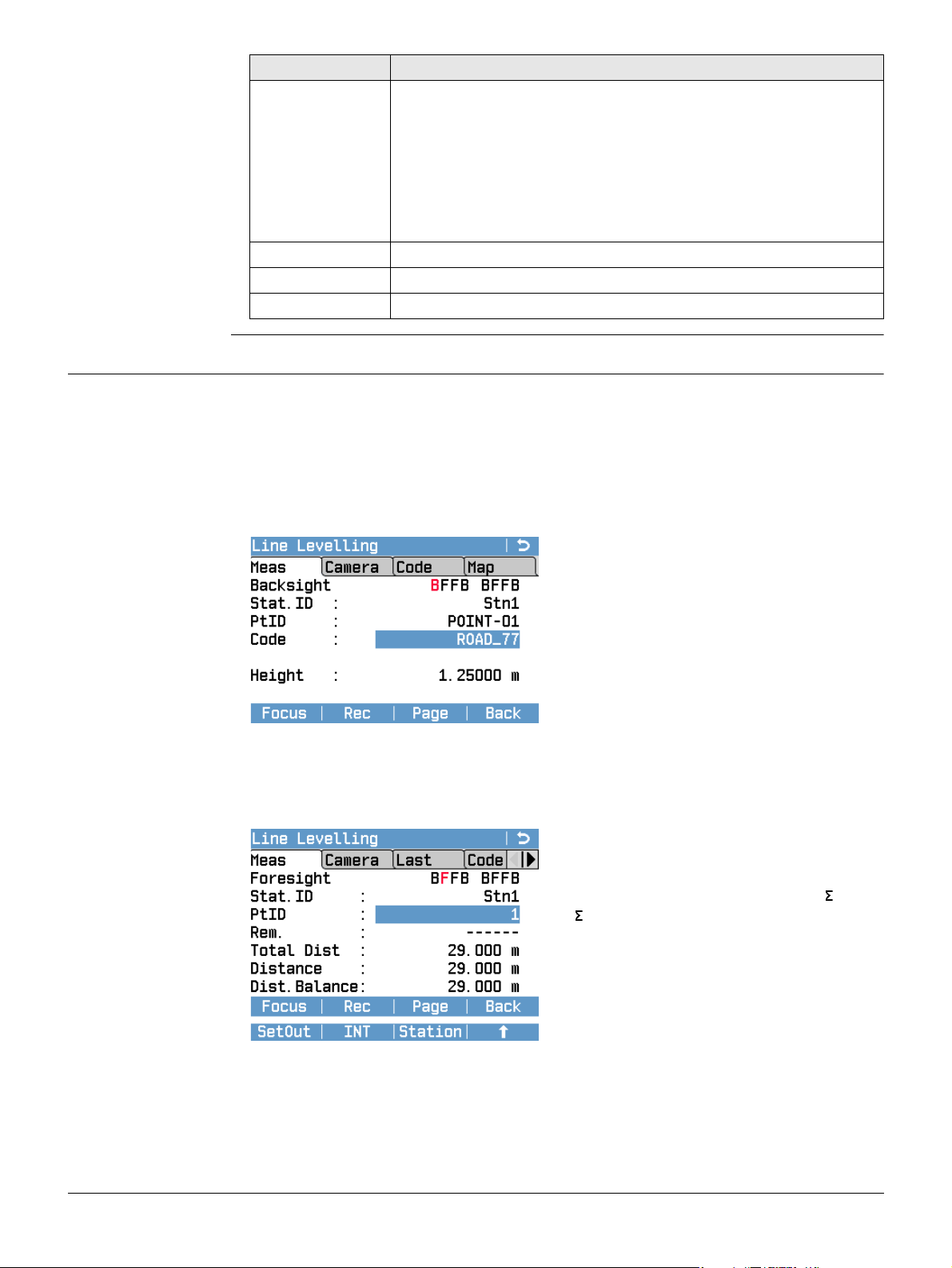
Field Description
• SimBF: This levelling method allows to simultaneously measure
two lines that have the same start and end point. Backsight
and foresight are measured according to the pattern BF(Line1)
BF(Line2) BF(Line1) BF(Line2).
• SimBFFB: This levelling method allows to simultaneously
measure two lines that have the same start and end point.
Backsight and foresight are measured according to the pattern
BFFB(Line1) BFFB(Line2) BFFB(Line1) BFFB(Line2).
PtID ID of the starting point.
Start H Height of the starting point.
Staff 1, Staff 2 Designations for first and second staff (optional).
7.4.5 Measurement Procedure for LineLevel
Measurement
Procedure
If a new line is started, the first measurement screen is either the backsight or the
foresight measurement, depending on the selected levelling method. On each screen,
the current measurement (Backsight/Foresight) is indicated by the viewing direction
which is highlighted in red.In the following example, the levelling method BFFB is used
to described the measurement procedure of the LineLevel application. For other levelling methods, the sequence of screens may differ.
First Backsight Screen (Station1)
Backsight/Foresight: The selected levelling
method. The current viewing direction is
highlighted in red.
Stat.ID: ID of the current station.
PtID: ID of the start point.
Rem/Free Code: If desired, you can enter
an additional remark to be stored with the
measurement.
Height: Height of the start point.
First Foresight Screen (Station1)
To take a measurement, aim at the staff and press the trigger key. If the trigger
key is set to Dist or AF+Dist (only LS15), press Rec (F2 softkey) to store the
measurement and switch to the next measurement screen.
Total Dist: Total length of the line.
Distance: Measured distance between
station and staff.
Dist.Balance: Distance difference ( sum B
- sum F) at the current station of the line.
LS10/LS15, Programs
58
Page 59
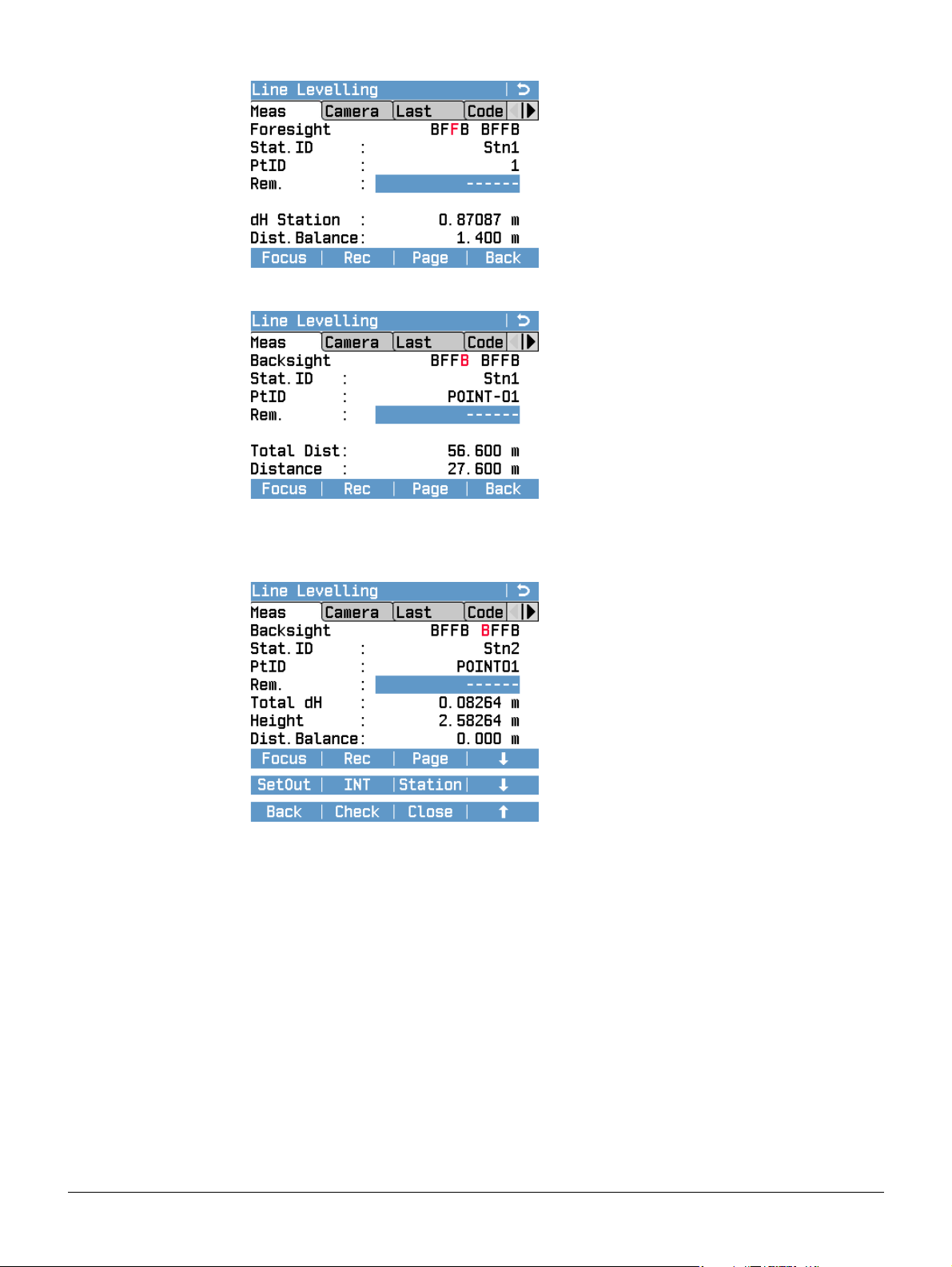
Second Foresight Screen (Station1)
dH Station: Height difference on the
current instrument station.
Second Backsight Screen (Station1)
Total Dist: Total length of the line.
Distance: Measured distance between
station and staff.
First Backsight Screen (Station2)
The field Stat.ID displays the ID of the next station. In the Backsight/Foresight field,
the first viewing direction of the next station is highlighted in red.
Total dH: Height difference between start
and current backsight.
Height: Height of current backsight.
LS10/LS15, Programs
As soon as all measurements of a station are completed you can access the functions
SetOut or INT. For a detailed overview about when these functions are available, refer
to " Availability of the Softkeys SetOut and INT". For a detailed description of the
SetOut and INT functions, refer to "7.2.2 Measurement Procedure for Q-Level".
After finishing all backsight and foresight measurements of a station, the following
three softkeys are available on the screen of the next station:
Station: To show the result screen of the previous station.
Check: To check the height of the last measured point with the height of a known
point (fixpoint).
Close: To start the calculation of the line end.
59
Page 60
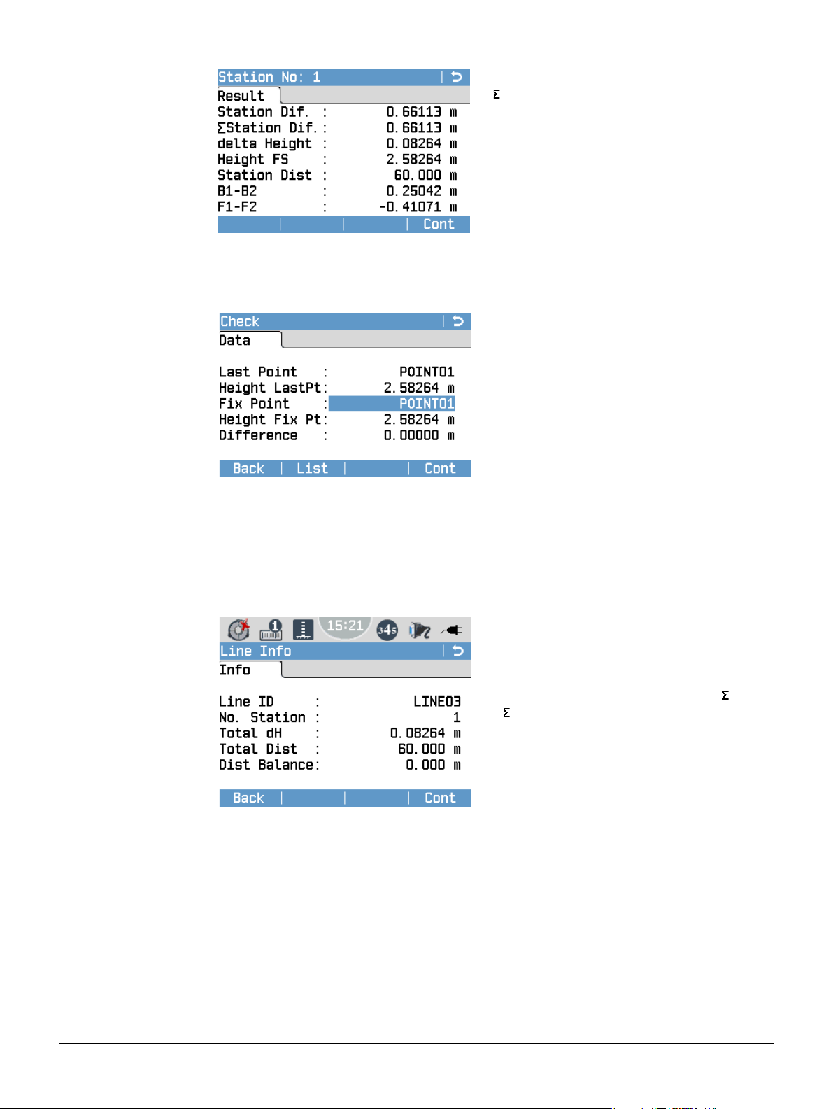
Station Result Screen
Check Screen
Station Dif.: Station difference.
Station Dif.: Accumulated station differ-
ence.
delta Height: Height difference between
backsight and foresight.
Height FS: Height of the foresight point.
Station Dist: Distance measured on this
station (backsight + foresight).
B1-B2: Difference between the two backsight height measurements.
F1-F2: Difference between the two foresight height measurements.
Last Point: Point ID of the last measured
point.
Height LastPt: Height of the last measured
point.
Fix Point: Point ID of the selected fixpoint.
Height Fix Pt: Height of the selected
fixpoint.
Difference: Height difference between
measured point and fixpoint.
To select a fixpoint from the available list of fixpoints, press the softkey List.
Closing a Line After completing all measurement of a station you can compare the height of the last
point of a line with a known fixpoint and calculate the misclosure. Press the softkey
Close to start the caculation of the line end.
Line Info Screen
Line ID: Line ID.
No. Station: Number of stations.
Total dH: Total height difference.
Total Dist: Accumulated distances.
Dist Balance: Distance difference ( sum B
- sum F) at the current station of the line.
LS10/LS15, Programs
60
Page 61
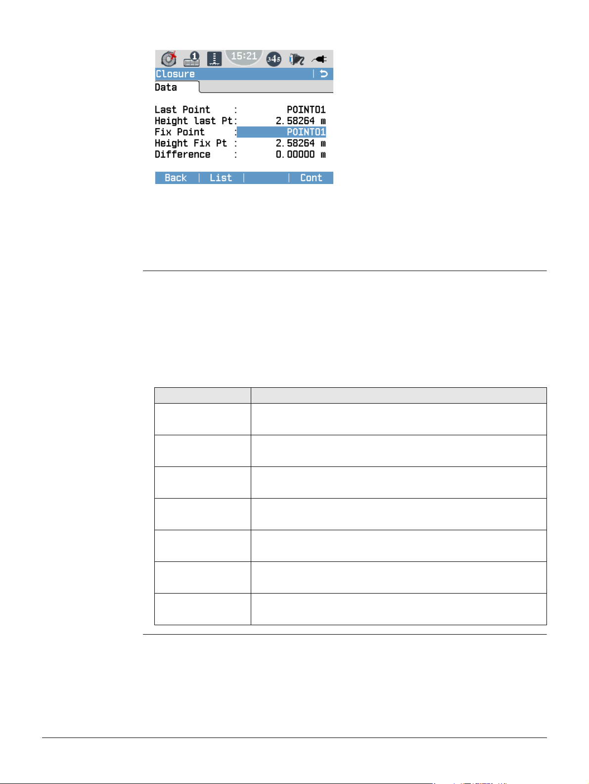
Closure Screen
Last Point: Point ID of the last measured
point.
Height LastPt: Height of the last measured
point.
Fix Point: Point ID of the selected fixpoint.
Height Fix Pt: Height of the selected
fixpoint.
Difference: Height difference between
measured point and fixpoint.
To select a fixpoint from the available list of fixpoints, press the softkey List.
To store the date and return to the Main Menu, press the softkey Cont.
If the misclosure is out of tolerance, an information message is displayed. To
return to the Closure Screen, press the softkey Abort. To ignore the message
and continue storing the data, press the softkey Cont.
Availability of the
Softkeys SetOut and
INT
The following table describes the availability of the softkeys SetOut and INT within the
LineLevel application, depending on the selected levelling method. Both functions are
only available after the first sequence of backsight and foresight measurements has
been completed (except for the BF method).
SetOut and INT are available
x: SetOut and INT are not available
: SetOut and INT are available
Levelling Method Availability
BF BF BF
x
BFFB BFFB BFFB BFFB
xxxx xxx xxx
BBFF BBF F BBFF BBF F BBFF
xxxx xxx xxx xxx
BFBF BF BF BFBF BF BF BFBF
xxxx xxx xxx xxx
aBF BF FB BF FB
xx x x x
aBFFB BFF B FBBF BFFB FBBF
xxxx xxx xxx xxx
aFBBF FBBF BFFB FBBF BFFB
xxxx xxx xxx xxx
LS10/LS15, Programs
61
Page 62
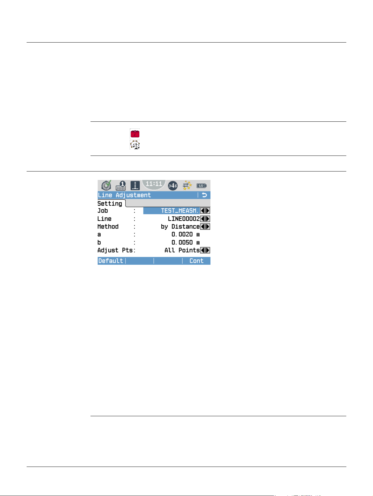
7.5 LineAdjust Program
7.5.1 General
Description The program LineAdjust allows you to adjust single level lines which have been meas-
ured with the LineLevel application.
• Define the general parameters for the adjustment procedure.
• Select any two points of the line as control points. Enter their heights or take over
the heights from the fixpoints.
The program calculates the misclosure between the measured total height difference
and the height difference calculated from the two control points. Based on the misclosure and the selected distribution method, the program calculates and stores adjusted
heights for all points in the line.
Access
1. Select Programs from the Main Menu.
2.
Select LineAdjust from the Programs Menu.
7.5.2 Line Adjustment Step-by-Step
Define Parameters
for Adjustment
Procedure
Job Select a job that contains level lines.
Line Select a level line in the current job. You can only adjust lines that
are recorded with the LineLevel program.
If no line to adjust is available, the symbol * is displayed.
Method Select one of the following methods for the line adjustment proce-
dure. The selected method is used to calculate the closing tolerance:
• by Distance:
Closing tolerance = a + b *√L (L = total line length)
• by Station:
Closing tolerance = a * √n (n = total number of stations)
a and b These parameters are used to calculate the closure tolerance
according to the described formulas.
Adjust Pts Select the type of points that you want to adjust:
• All Points
• Line+Interm.
• Line+SetOut
• Line only
To reset the default parameters for
Method, a, b, and Adjust Pts, press
Default.
To continue with the adjustment procedure, press Cont.
LS10/LS15, Programs
62
Page 63
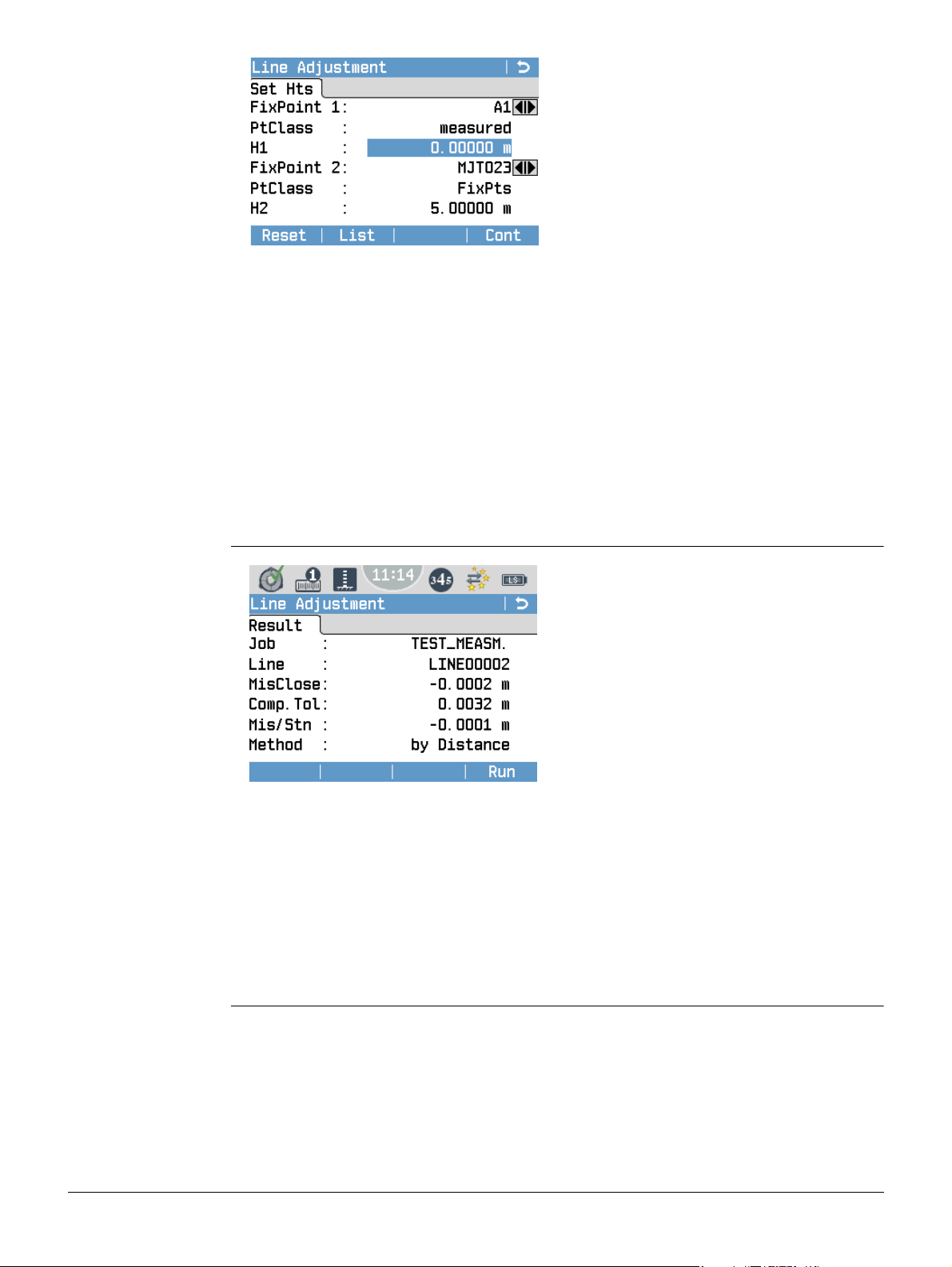
Define Two Control
Points
To reset the selected points and their
heights to the default value, press Reset.
To calculate the misclosure and to view
the adjustment results, press Cont.
FixPoint 1/FixPoint 2 Select any two points of the line as first and second control
point. The default point ID is the start point of the selected
line.
PtClass Displays the type of the selected point (measured point,
fixpoint, adjusted point).
H1, H2 Displays the height of the selected point. If you change the
point ID, the height stored for this point ID is displayed.
For points of the type “measured“, you can change the
height. Either enter the height directly or press List to select
a point with the desired height from the list of available
points.
If the misclosure exceeds the closure tolerance, a warning message appears.
Press Cont to ignore the message and continue the procedure. Press Abort to
cancel the procedure and change the settings on the previous screen.
Adjustment Results
MisClose Calculated misclosure of the line at the second control point.
Comp.Tol Calculated closing tolerance according to the selected method.
Mis/Stn Calculated misclosure per station.
Method Method that was used for the adjustment.
• by Distance: the misclosure is distributed to the points of the
level line according to the distances between the staffs.
• by Station: the misclosure is distributed according to the
number of stations of the level line and is thus independent of
the distances between the staffs.
To adjust and record all points of the selected type of points, press Run.
LS10/LS15, Programs
63
Page 64
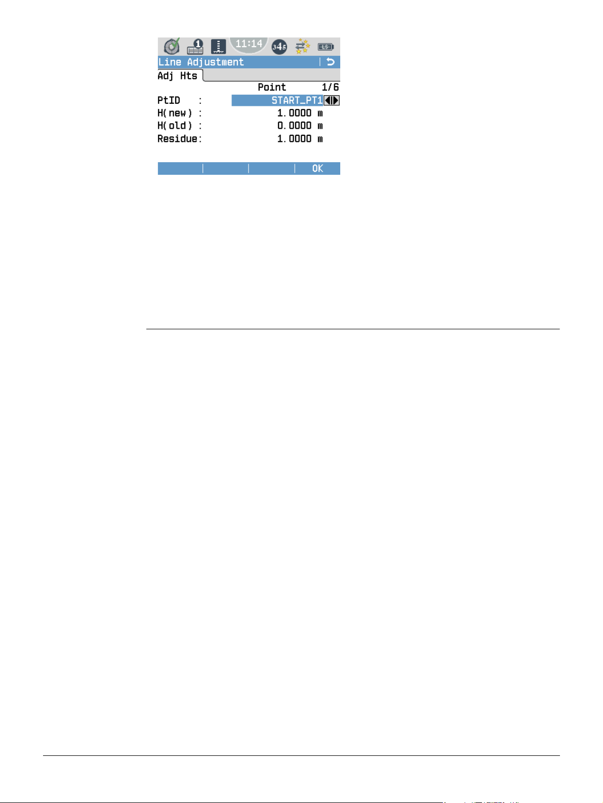
Adjusted Heights
Point: Displays the number of points that were adjusted.
PtID Displays the current point ID. Use the navigation keys to scroll
through the point IDs.
H(new) Displays the adjusted height of the selected point.
H(old) Displays the originally measured height of the selected point.
Residue Displays the height difference (residual) between the original and
the adjusted height of the selected point.
To exit the screen and end the program, press OK.
The original measurements are kept in the job and are stored as measured
triplets. For each adjusted point, an adjusted triplet is created additionally and
stored to the current job.
LS10/LS15, Programs
64
Page 65
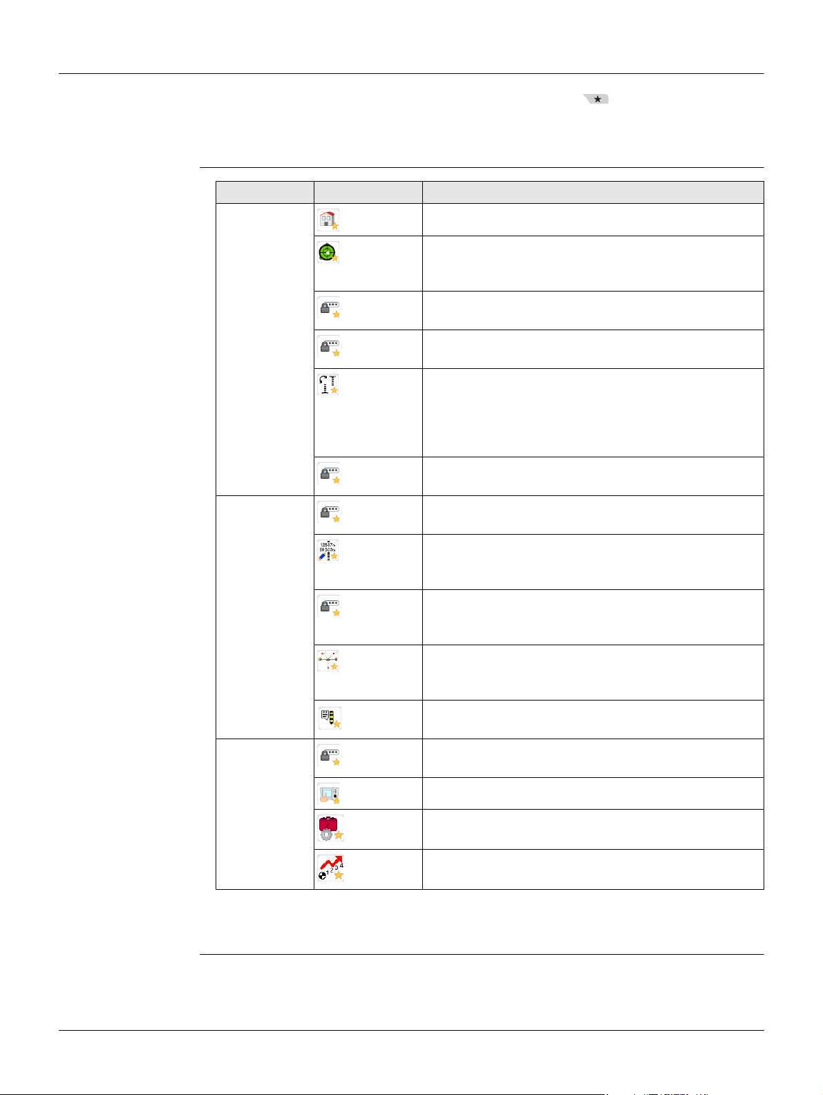
8 Favourites
Description Favourites can be accessed by pressing the Favourites key from any measurement
screen.
The Favourites key opens the Favourites Menu and a function can be selected and
activated.
Favourites
Work
Apps
Setting
Favourite Description
Home
Level
PIN
Free Code
INV
View Meas
Adjust
Man.Input
Setout
Interm
Free code
Mode
Touch
Work
PtID Incr
Returns to the Main Menu.
Opens the Level & Tilt Check screen. Refer to "For
LS15: Level Up with the Electronic Level Step-byStep".
Allows you to lock the screen with a PIN. Refer to
"12.4 Instrument Protection with PIN".
Opens screen to view, create or delete codes. Refer
to "9 Coding".
Changes the orientation of the staff (upright or
inverse). Note that the selected earth curvature
correction setting remains unchanged. To change
the earth curvature correction refer to "6.2 Regional
Settings".
To view measurement data for a selected job. Refer
to "13 Data Management".
Opens the LineAdjust program. Refer to "14 Check
& Adjust".
To manually enter staff readings and distances
between staff and instrument. Refer to "5.4 Manual
Input Screen for Optical Height Reading".
Opens the Setout screen. Refer to " SetOut Application" within "7.2.2 Measurement Procedure for QLevel".
To activate the Intermediate point measuring function. Refer to " Survey Intermediate Points" within
"7.2.2 Measurement Procedure for Q-Level".
Opens the Free Code screen from within a levelling
application. Refer to "10 Free Coding".
Opens the screen to change the mode settings.
Refer to "6.5 Mode Settings".
To activate/deactivate the touch screen.
Opens the Work Settings screen.
Refer to "6.1 Work Settings".
Opens the Point ID & Incrementation screen. Refer
to "6.1 Work Settings".
LS10/LS15, Favourites
In addition to the Favourites key, you can use the User Key 1 and User Key 2
to quickly access functions from any measurement screen. For details on how
to assign functions to the User keys, refer to "6.1 Work Settings".
65
Page 66
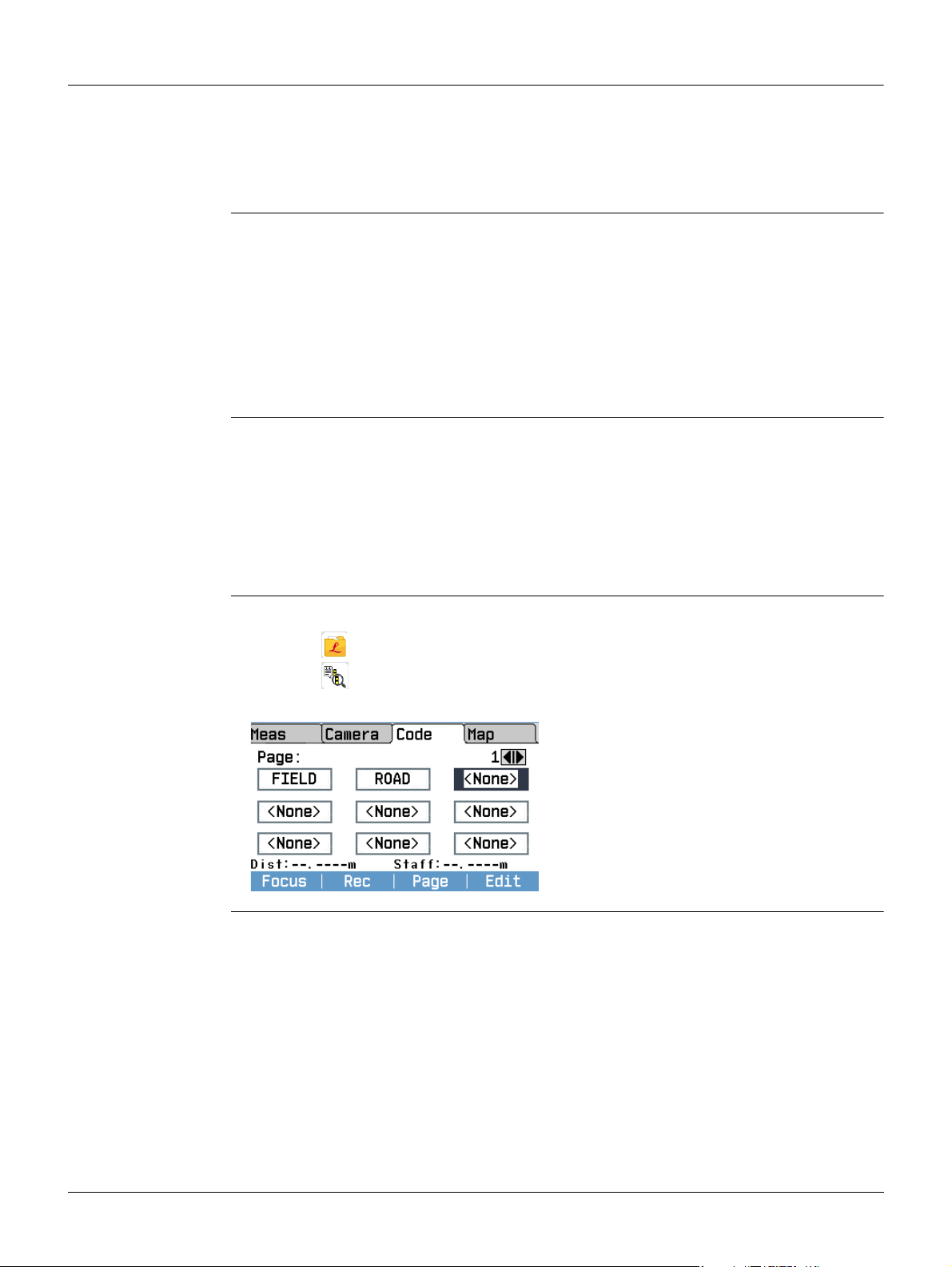
9Coding
Description Codes contain supplementary information about recorded points and are stored as
code blocks together with the measurements. Both, coding with and without a
codelist is supported.
With the help of coding, points can be assigned to a particular group of information
to simplify later processing.
Creating a Codelist A codelist can be created:
•on the instrument.
•in Infinity.
Codelists can be imported and exported via USB memory stick. Refer to "13.2
Exporting Data" and "13.3 Importing Data".
Number of codes supported in codelists:
• Up to 500, when created in Infinity.
• Up to 200, when created on the instrument.
GSI coding Codes are always stored as free codes (WI41-49), that means that codes are not
directly linked to a point. They are stored before or after the measurement depending
on the setting made.
A code is always recorded for each measurement as long as a code is highlighted
within the page Code. To stop recording a code, ensure that no code field is highlighted within the page Code.
For permanent recordings of points or a reset of the code recording after storing a
point, refer to "6.3 Data Settings".
Access Direct Access to Codelists
•Select Manage from the Main Menu.
•Select Codes from the Manage Menu.
Access from within a program
•Open the Q-Level or the LineLevel
program.
• Within the program, press Page to
change to the page Code.
• Press Edit to open the Manage Codes
screen.
LS10/LS15, Coding
66
Page 67
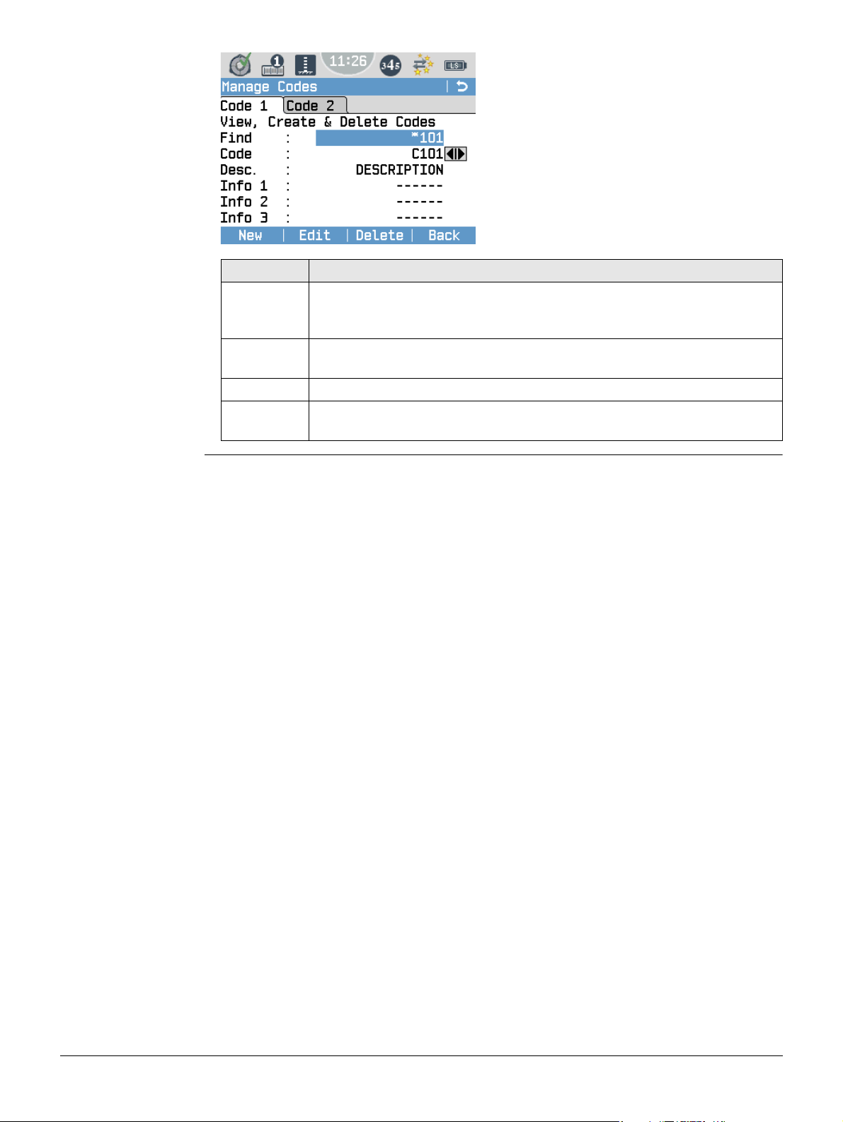
Manage Codes
New
To create a code.
Edit
To edit the selected code.
Delete
To delete the selected code.
Field Description
Find Enter a code name to search for existing codes. If the entry does not
match any existing code name, a warning message is displayed and a
wildcard is automatically inserted into the field.
Free Code List of existing code names. Use the navigation keys to toggle through
the list.
Desc. Additional remarks.
Info 1 to
Info 8
More information lines, freely editable. Used to describe attributes of
the code.
LS10/LS15, Coding
67
Page 68
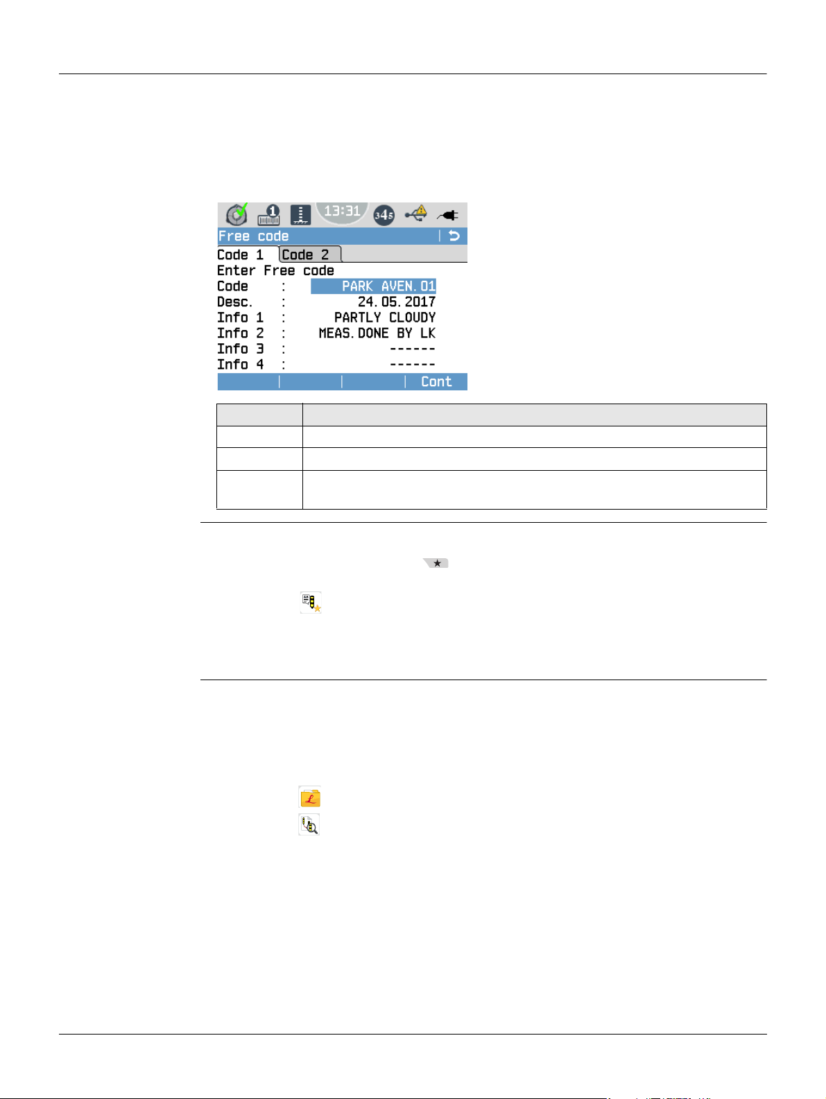
10 Free Coding
Free code function In addition to recording codes for measured points, it is possible to store multiple free
codes within a job. Such free codes are not related to a specific point measurement.
Use the Free code function e.g. to enter additional information on the current job or
line. This information can be used for the postprocessing of the measurement data.
Field Description
Code Enter a code name. You can enter up to 16 characters.
Desc. Additional remarks. You can enter up to 16 characters.
Info 1 to
Info 8
Free codes can be entered and stored at any desired point of time during a job,
for example before any point is measured or in between measurements.
Cont
To store the entered code.
More information lines, freely editable. You can enter up to 16 characters.
Access
Manage free codes
1.
2. Change to the Apps tab.
3.
View a stored Free code
1. Select Manage from the Main Menu.
2. Select Meas.Data to display the Manage Measurements screen.
3. Select the job containing the free codes and press the softkey View (F4)
4. Toggle through the list of data blocks until a free code block is displayed.
The Free Code screen can only be accessed from within a levelling application.
Press the Favourites key.
Select Free Code.
In addition to the Favourites key, you can use the User Key 1 and User Key 2
to quickly access functions from any measurement screen. For details on how
to assign functions to the User keys, refer to "6.1 Work Settings".
Free c od es a re st o re d a s in di v id ua l da t a b lo c ks wi t hi n a j ob , n a me ly i n t he o rd e r
they are recorded. These data blocks are classified as “Code/Rem.“.
To export free codes, export the job containing the free codes in the GSI
format.
LS10/LS15, Free Coding
68
Page 69
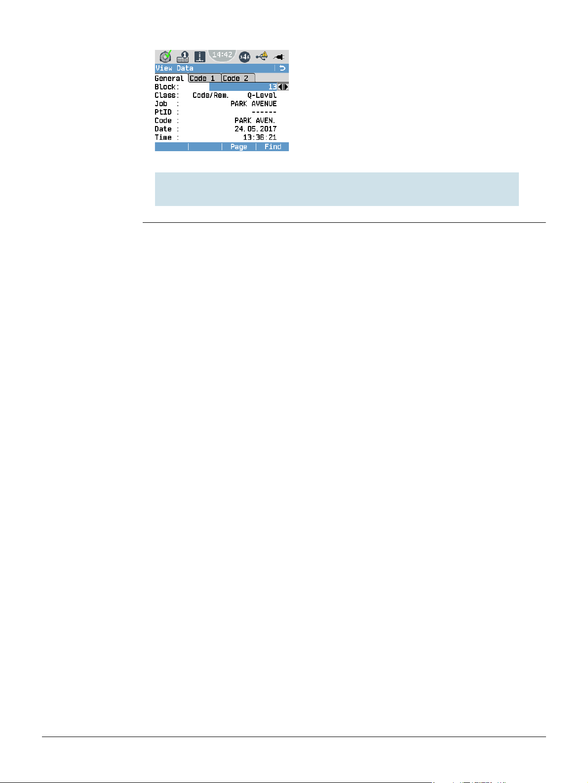
Example of a Free code data block:
Page
To toggle between the pages of the data block
(General, Code 1, Code 2).
Find
To display the Manage Measurements screen and
select a different job.
Example of a GSI-8 output:
410001+PARK AV. 42....+PARTLY CLOUDY 43....+MEAS.DONE BY LK 44....+00000000 45....+00000000
46....+00000000 47....+00000000 48....+00000000 49....+00000000
014617_001
LS10/LS15, Free Coding
69
Page 70
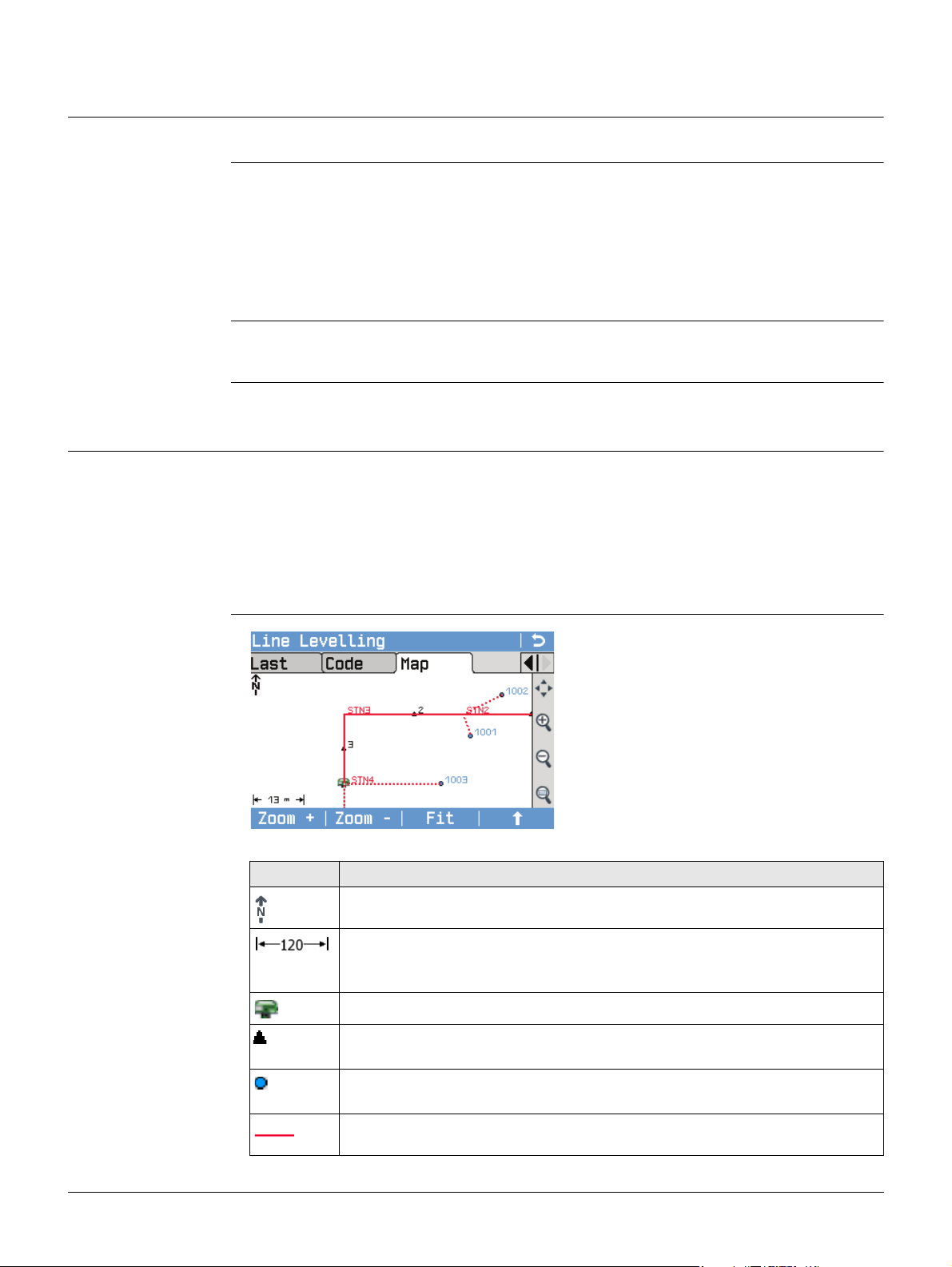
11 MapView
11.1 Overview
Availability The MapView functionality is only available on the LS15 instrument.
Description MapView is an interactive display feature embedded in the firmware. MapView
provides a graphical display of the current and the last four instrument stations. In the
MapView, all line measurements and intermediate sights are drawn according to their
orientation to give a better understanding of how the different measurement data are
related to each other.
The displayed data in all modes of MapView can be shifted by using both the arrow
keys and the touchscreen.
Access The MapView functionality is provided as a page within applications.
Within Q-Level or LineLevel, change to page Map.
11.2 MapView Components
11.2.1 Screen Area
Description Standard functionality is provided by softkeys, keys and a toolbar within MapView.
The softkeys are available regardless of the mode in which MapView was accessed and
always perform the same functions.
On the right side of the screen, a toolbar with icons is available. Some functions of the
toolbar can also be performed by using a softkey or key instead. Refer to the following
table for a description of the toolbar functions and their respective softkey/key equivalents, if available.
Elements of the
Map Page
009170_001_en
Symbol Description
North arrow. North is always orientated towards the top of the screen.
Scale of the current screen. The minimum is 0.04 m. There is no
maximum for the zoom but the scale cannot display values greater than
99999 m. In this case the value displayed will be >99999 m.
Position of the instrument station. The ID of a station is displayed in red.
Position of the foresight or backsight staff. The ID of the measured
points is displayed in black.
Intermediate point / Set-out point. The ID of such a point is displayed in
blue.
Measured line to the staff.
LS10/LS15, MapView
70
Page 71
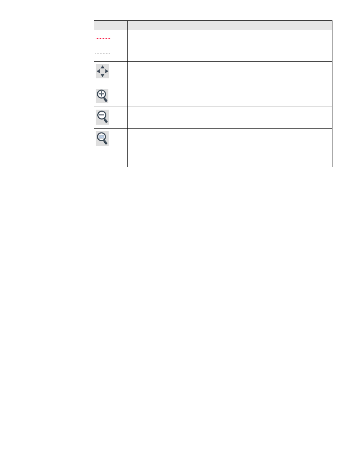
Symbol Description
Measured line to an intermediate or a set-out point.
Current viewing direction of the instrument.
The fit icon fits all displayable data, according to filters and the map
configuration, into the screen area, using the largest possible scale.
Tap on the icon or press the softkey Fit (F3).
To zoom into the map.
Tap on the icon or press the softkey Zoom + (F1).
To zoom out of the map.
Tap on the icon or press the softkey Zoom - (F2).
The windowing icon zooms to a specified area window. An area window
can be drawn by dragging the stylus on the screen in a diagonal line to
make a rectangular area or by tapping twice on the screen to define diagonally opposite corners of a rectangular area. This action causes the
screen to zoom to the selected area.
To move the view of the map up and down as well as left and right, tap on the
screen with the stylus, hold and move. You can also use the navigation keys.
Moving the map is useful when you have zoomed in on a view, and want to
move the view around to see other areas of interest.
LS10/LS15, MapView
71
Page 72
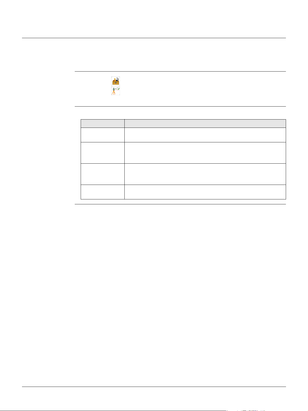
12 Tools
12.1 Adjust
Description The Check & Adjust Menu contains tools to be used for the electronic adjustment of
the line of sight, for the alignment of the camera crosshair and for the compass calibration of the instrument. Using these tools helps to maintain the measuring accuracy
of the instrument.
Access
Adjustment Options In the Check & Adjust screen, there are several adjustment options.
1.
Select Tools from the Main Menu.
2. Select Adjust from the Tools Menu.
3. Select an Adjustment option from the Check & Adjust screen.
Menu selection Description
F1 Line Of Sight To check and adjust the line-of-sight error. Refer to "14.3
Adjusting Line-of-Sight Error".
F2 Camera
Crosshair
F3 Digital
Compass
F4 Level Bubble To adjust the electronic level of the instrument. Refer to "14.8
Only for LS15:
To align the camera crosshair (vertically arranged indicators) to the
staff. Refer to "14.5 Aligning the Camera Crosshair".
Only for LS15:
To calibrate the digital compass. Refer to "14.6 Calibrating the
Digital Compass".
Adjusting the Electronic Level".
LS10/LS15, Tools
72
Page 73
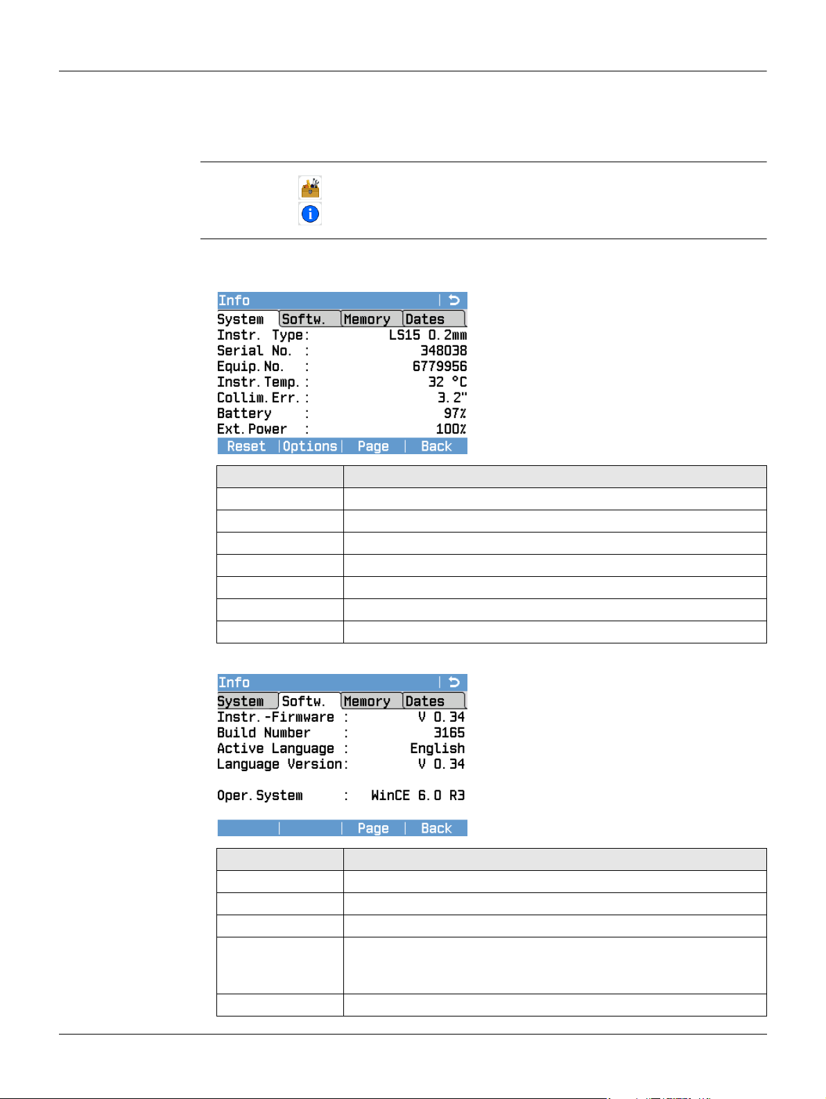
12.2 System Information
Description The Info screen displays instrument, system and firmware information.
Please provide the instrument-related information, such as instrument type,
serial number and equipment number, as well as the firmware version and build
number when contacting support.
Access
Info Page 1/4 (System)
1.
Select Tools from the Main Menu.
2. Select Info from the Tools Menu.
This screen displays information about the instrument and operating system.
Field Description
Instr. Type Displays the instrument type.
Serial No. Displays the serial number of the instrument.
Equip.No. Displays the equipment number.
Instr.Temp. Displays the current temperature of the instrument.
Collim.Err. Displays the current collimation error (line-of-sight error).
Battery Displays the current capacity of the internal battery.
Ext.Power Displays the current capacity of the external power supply.
Reset
To reset all settings to the system
default.
Options
To display hardware related options
which this particular instrument
provides.
LS10/LS15, Tools
Page 2/4 (Softw.)
Field Description
Instr.-Firmware Firmware version
Build Number Build number of the current firmware version
Active Language Currently activated user interface language
Language Version Version of the currently used language file.
Oper.System Operating System installed on the instrument
Firmware version and language version should always be
identical.
73
Page 74
Page 3/4 (Memory)
Displays job-specific memory information such as the number of stored stations and
fixpoints within a job, the number of recorded data blocks, for example measured
points, or codes within a job, and the memory space occupied.
Page 4/4 (Dates)
Field Description
Maint.-End Date Displays the end date of the maintenance agreement for the
mySec.Renewal
Date
Next Service Date Displays the date of the next required service check. The field can
Before pressing Format, to format the internal memory, ensure that all important data is first transferred to a computer. Jobs, formats, codelists, configuration files, uploaded languages and firmware are deleted by formatting.
Despite an automatic defragmentation, the memory gets fragmented after a
while. Please format the internal memory periodically to maintain the instrument performance.
12.3 Licence Keys
instrument firmware.
The date when the instrument must be connected to mySecurity
in order to renew the security functionality.
be invisible if turned off by the service reminder.
Description To fully activate firmware contracts, it may be necessary to load a valid licence key on
the instrument. To load a licence key, carry out the procedure described in the
following paragraph.
Loading a Licence
Key
Step Description
1. Copy the licence key into the system directory (e.g. D:\system\) of the USB
memory stick.
2. Insert the USB memory stick into the USB interface within the battery
compartment.
3. Select Tools from the Main Menu.
4. Select Licence from the Tools Menu.
5. An information message is displayed. To confirm, press Cont. The licence key
is loaded automatically on the instrument.
LS10/LS15, Tools
74
Page 75
12.4 Instrument Protection with PIN
Description The instrument can be protected by a Personal Identification Number. If PIN protection
is activated,the instrument will always prompt for a PIN code entry before starting up.
If a wrong PIN has been entered five times, a Personal UnblocKing (PUK) code is
required.
Activate PIN code
Step-by-Step
Lock Instrument
Step-by-Step
Resetting the PIN
with the PUK Code
Step Description
1. Select Tools from the Main Menu.
2.
3. Activate PIN protection by setting Use PIN-Code: On.
4. Enter a personal PIN Code in the New PIN-Code field. The PIN code must have
5. Accept with Cont.
Now the instrument is protected against unauthorised use. After switching on the
instrument, a PIN code entry is necessary.
If PIN protection is activated, it is possible to lock the instrument from within any
program without switching off the instrument.
Step Description
1.
2. Select PIN from the Favourites Menu.
If a wrong PIN is entered five times, the system prompts for a personal unblocking
(PUK) code. The PUK code is a licence key.
When you load the licence key file with the correct PUK code, the instrument starts up
and resets the PIN code to default value 0 and Use PIN-Code: Off.
Refer to "12.3 Licence Keys" for instructions on how to load a licence key.
Select PIN from the Tools Menu.
exactly five numerics.
Press the Favourites key when within any program.
Deactivate PIN Code
Step-by-Step
LS10/LS15, Tools
Step Description
1.
2. Select PIN from the Tools Menu.
3. Enter the current PIN in PIN-Code:.
4. Press Cont.
5. Deactivate PIN protection by setting Use PIN-Code: Off.
6. Accept with Cont.
The instrument is now no longer protected against unauthorised use.
Select Tools from the Main Menu.
75
Page 76
12.5 Loading Software
Description You can load a firmware file or additional languages on the instrument. To load a firm-
ware or language file, carry out the procedure described in the following paragraph.
Loading Firmware
and Language Files
• Never disconnect the power supply during the system upload process. The battery
must be at least 75% capacity before commencing the upload.
Step Description
1. Copy the firmware and language file into the system directory (e.g.
D:\system\) of the USB memory stick.
2. Insert the USB memory stick into the USB interface within the battery
3. Select Tools from the Main Menu.
4. Select Load FW from the Tools Menu.
5. • To load firmware and language files together, select F1 Firmware.
6. To start loading the files, press Cont. Once the files are successfully loaded,
Loading a firmware file always requires to load a language file simultaneously. Before you start the process, ensure that the system directory of the
USB contains the firmware file and at least one language file.
compartment.
The Select File! screen is displayed. Select the firmware file from the
system directory of the USB memory stick.
Press Cont to display the Upload Languages! screen.
• To load only one or several language files, select F2 Language(s) only.
The Upload Languages! screen is displayed. To define which languages
you want to load, select Yes or No for each language file. At least one
language must be set to Yes.
the system shuts down and restarts again automatically.
LS10/LS15, Tools
76
Page 77
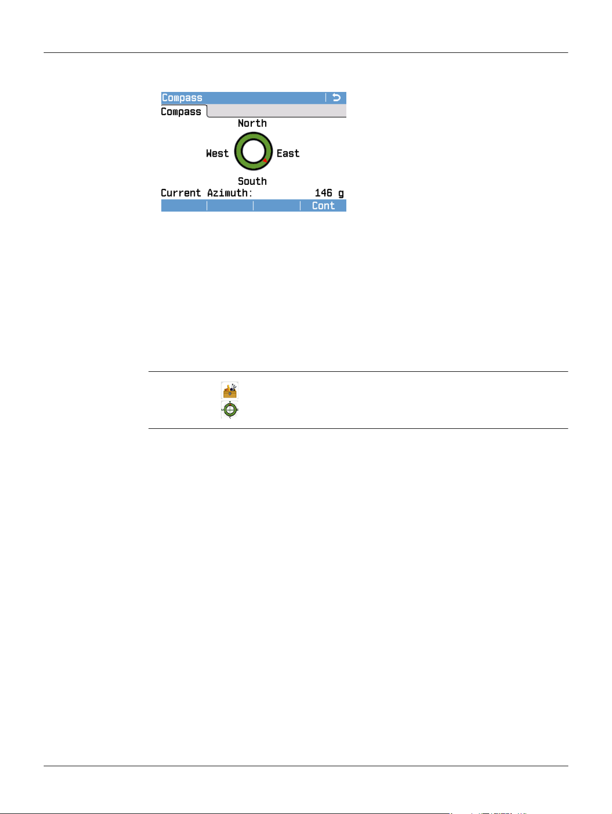
12.6 Compass
Description The digital compass is only available on the LS15 instrument.
The Compass screen displays the current compass reading.
You can use the digital compass to turn the instrument to a specific direction. For each
measurement taken with a LS15 instrument, the coordinates of a measured point are
stored. The estimated coordinates can be imported into Infinity to visualise the direction of a levelling line.
The digital compass is sensitive and can be interfered by magnetic fields. Avoid
using the compass in areas or environments that may interfere with the quality
of the compass measurements. The interference can affect the accuracy and
quality of the coordinates/positions determined.
For correct measurement results, it is recommended to perform a compass
calibration every time you set up the instrument. For this purpose, you can
define the compass calibration screen as start screen. Refer to "6.1 Work
Settings".
Access
1. Select Tools from the Main Menu.
2.
Select Compass from the Tools Menu.
LS10/LS15, Tools
77
Page 78
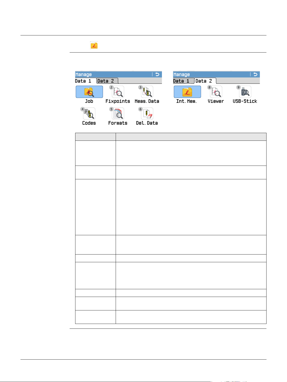
13 Data Management
13.1 Manage
Access Select Manage from the Main Menu.
Manage The Manage Menu contains all functions for entering, editing, checking and deleting
data in the field.
Menu item Description
Job To select, view, create and delete jobs. Jobs are a summary of
different types of data, for example, fixpoints, measurements or
codes. The job definition consists of the job name and user. The
system generates time and date at the time of creation.
Fixpoints To view, create, edit and delete fixpoints. Valid fixpoints contain at
least the point ID and the coordinates E, N or H.
Meas.Data To view, edit and delete measurement data. Measurement data
available in the internal memory can be searched for via a specific
point search, or by viewing all points within a job.
Codes To view, create, edit and delete codes. To each code a description
and a maximum of 8 attributes with up to 16 characters each can
be assigned.
Formats To view and delete data format files.
Del.Data To delete individual jobs, fixpoints and measurements of a specific
job or all jobs in the memory.
Int.Mem. To view, delete, or rename exported data files.
Viewer To view the contents of a data files stored in the internal memory
or on the USB memory stick.
USB-Stick To view, delete, rename and create folders and files stored on the
USB memory stick.
If the details of a point have been edited or updated, any
new calculations will use the new point details. However,
any previously stored calculation results based on the original coordinates of the point will not be updated. The same
applies to updates of delta height calculations and averages.
Deleting the memory cannot be undone. After confirming
the message all data is permanently deleted.
LS10/LS15, Data Management
78
Page 79
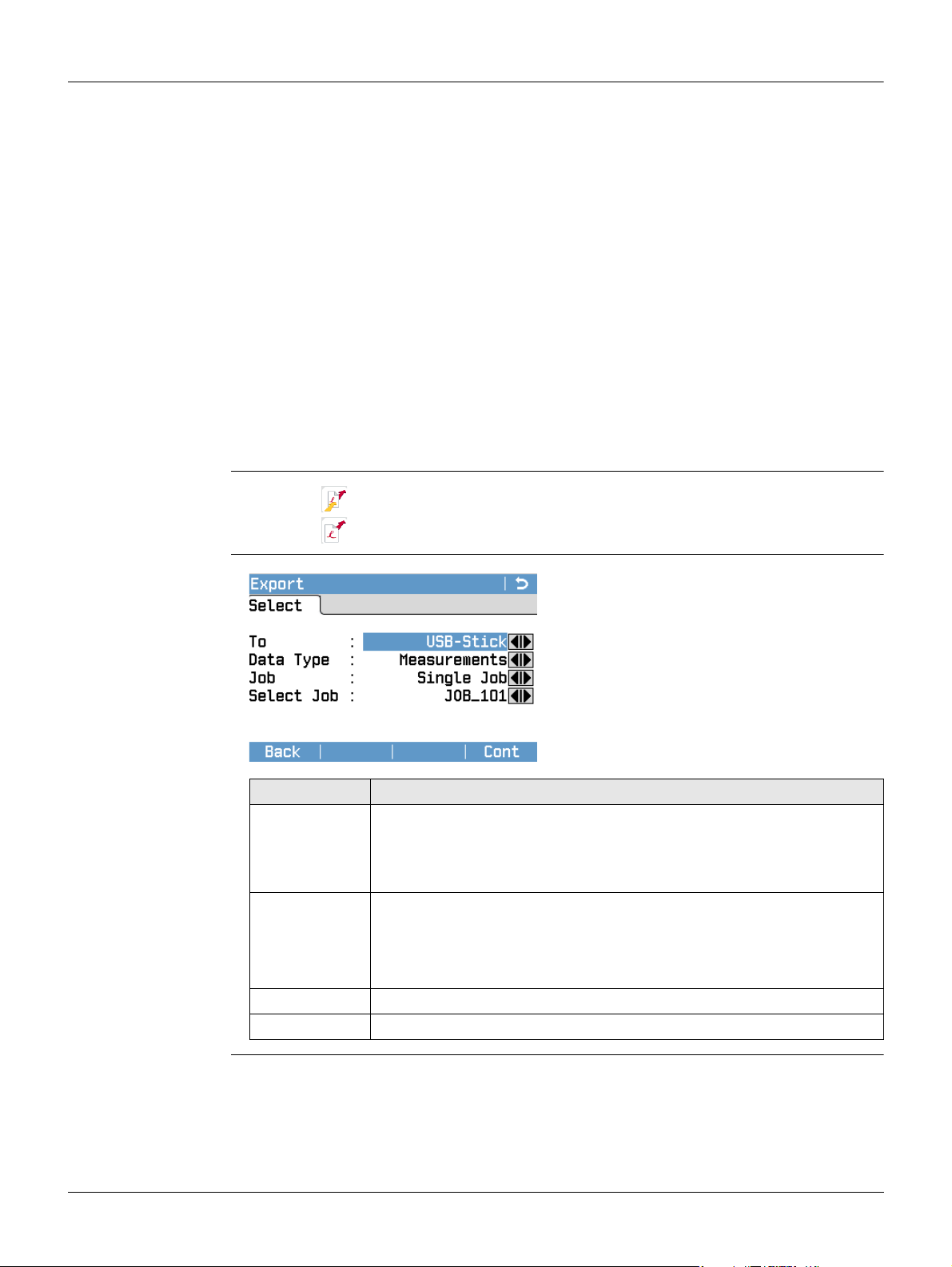
13.2 Exporting Data
Description Job data, format files, configuration sets and codelists can be exported from the
internal memory of the instrument. Data can be exported to:
1) Internal memory
The selected database content is translated into a readable ASCII, GSI or XML file and
stored in the internal memory of the instrument. If you connect the instrument to a
PC through Active Sync/Mobile Device Centre, you can copy these files to the PC by
drag and drop.
2) USB Memory Stick:
The selected database content is translated into a readable ASCII, GSI or XML file and
stored on the USB memory stick that is inserted into the USB interface.
3) RS232 or Bluetooth Interface:
The selected database content is translated into a readable ASCII, GSI or XML file and
send to an external receiver (e.g. a PC) using the RS232 or bluetooth interface.
To receive the data, the receiver needs to be equipped with a third party receiving
program.
Access 1) Select Transfer from the Main Menu.
2) Select Export.
If the receiver cannot process the data fast enough or if the connection to the
receiver is unstable, the exported data could be lost. Note, that for this type
of data transfer no protocol check exists.
Select Export
Details
Field Description
To Destination of the exported data:
• Internal Memory
• USB Stick
• Interface (RS232, Bluetooth)
Data Type Data type to be transferred:
To Internal Memory, USB Stick or Interface: Measurements,
Fixpoints, Meas.& Fixpoints
Only to USB Stick: Code, Format, Backup
Job Select whether to export all job-related data or a single job data file.
Select Job Displays the selected job.
LS10/LS15, Data Management
79
Page 80
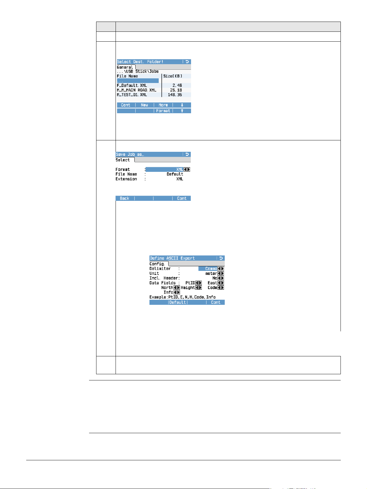
Export Data
Step-by-Step
Step Description
1. Select the export details in the Export screen and press Cont.
2. If the export destination is a USB memory stick or the internal memory, select
the desired file location.
Cont
To display the Save ... as screen.
New
To create a folder.
More
To display additional information: creation date,
creation time and file size.
Format
Only available if you select USB Stick as export destination. To delete all data
on the USB stick.
3. Within the Save ... as screen, select the data format and enter the file name.
Data Formats:
XML: Extensible Markup Language. XML is a recommendation of the
World Wide Web Consortium. Fixed format.
ASCII: American Standard Code for Information Interchange. Free
format. Usage and order of variables and delimiter can be defined
during import.
Define the delimiter value, the units
and the data fields of the file and press
Cont.
GSI: LeicaGeo Serial Interface. Fixed format. Select between GSI 8 and
GSI 16. Refer to " Exportable Job Data Formats" for an explanation
of the formats.
User
defined:
4. To start the data export, press Cont or Send.
After the data has been successfully exported, a message is displayed.
Any uploaded user defined format. To create a user defined
format, use the Format Manager. For details on how to upload a
format file, refer to Importing Data.
LS10/LS15, Data Management
Measurement data are stored in chronological order – line by line - on the instrument.The XML data format and other format files do not output data chronologically
but sort the data in separate blocks. During the data export in XML data format or
other format files, the instrument has to search the whole memory until the required
data is found. Therefore, the data transfer time varies between formats. The GSI data
format has the best transfer speed-performance.
80
Page 81
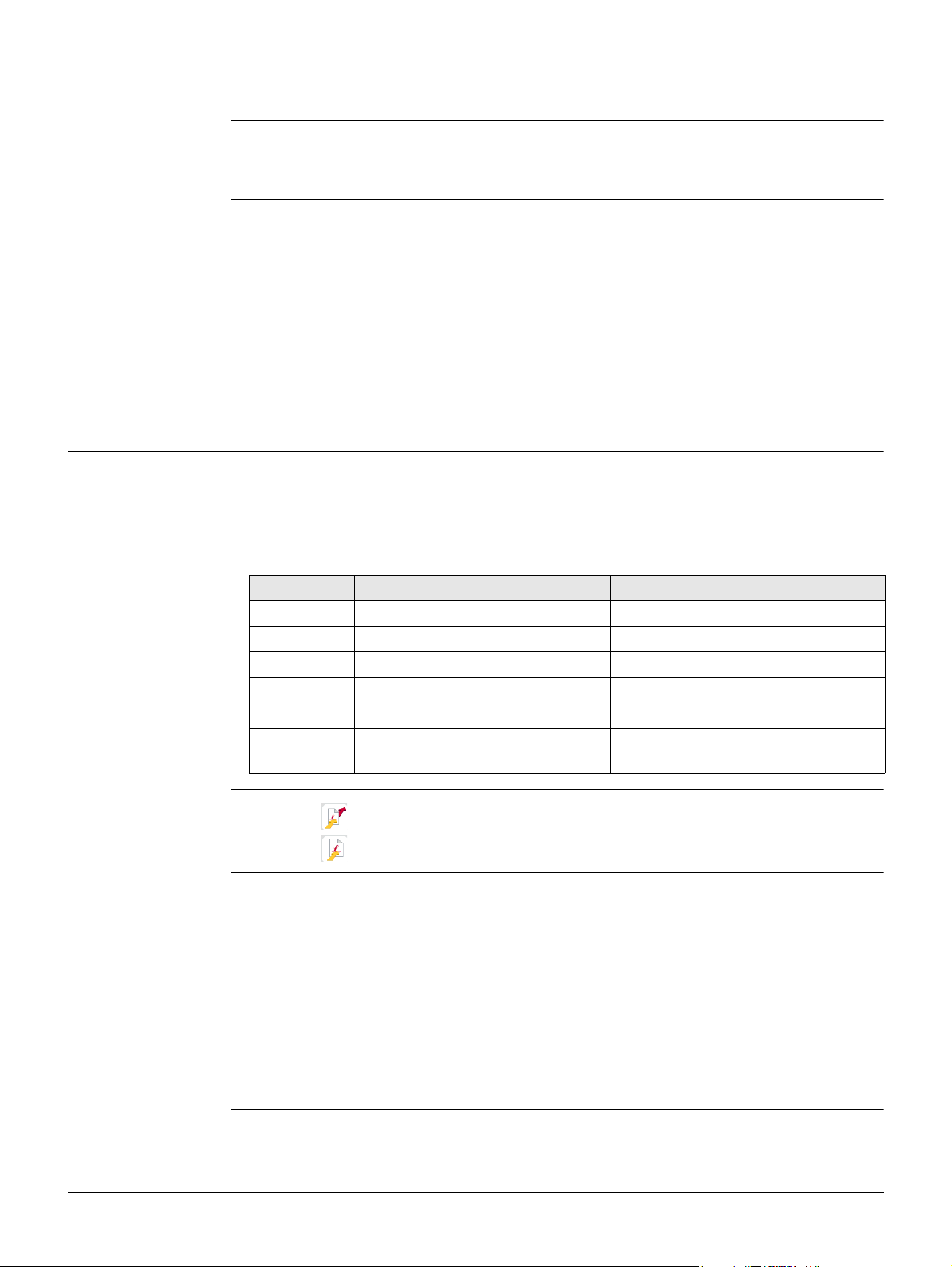
A ’+’, ’-’, ’.’ or alphanumerical characters should not be used as delimiter values in ASCII
files. These characters can also be part of the point ID or coordinate values and if so,
will generate errors where they occur in the ASCII file.
Exportable Job Data
Formats
All jobs, formats, codelists and configurations will be stored in the backup folder
created on the USB memory stick. The job data will be stored as individual database
files for each job, which can then be imported again. Refer to "13.3 Importing Data".
Job data can be exported from a job in GSI, ASCII and XML file types, or any other userdefined ASCII format. A format can be defined in the Format Manager tool delivered
with the instrument. Refer to the online help of the Format Manager tool for information on creating format files.
Example job data output
PtID East North Height Code Info1-8
POINT01 -2.0940 -59.9634 0.3003 MAIN_ROAD
POINT02 -4.1879 -119.9269 -0.0934 MAIN_ROAD
POINT023 -6.2819 -179.8903 -0.3782 MAIN_ROAD
13.3 Importing Data
Description Data can be imported to the internal memory of the instrument via a USB memory
stick.
Importable Data
Formats
When importing data, the instrument automatically stores the file in a directory folder
based on the file extension. The following data formats can be imported:
Data Type File extension Recognised as
GSI .gsi Fixpoints
HexXML .xml Fixpoints
ASCII any ASCII file extension e.g. .txt Fixpoints
Format .frt Format file
Codelist .cls Codelist file
Backup .db Backup of fixpoints, measurements
and configuration
Access 1) Select Transfer from the Main Menu.
2) Select Import.
LS10/LS15, Data Management
• Importing a backup folder will overwrite the existing configuration file and code lists
on the instrument, and all existing formats and jobs will be deleted.
• A backup can only be imported if the instrument database structure was not
changed by a firmware update. If the instrument firmware was updated, it can
happen that a backup created before the update cannot be imported. In this case,
downgrade the firmware to the previous used version, save the data in the way
required and then reload the new firmware.
A ’+’, ’-’, ’.’ or alphanumerical characters should not be used as delimiter values in ASCII
files. These characters can also be part of the point ID or coordinate values and if so,
will generate errors where they occur in the ASCII file.
81
Page 82
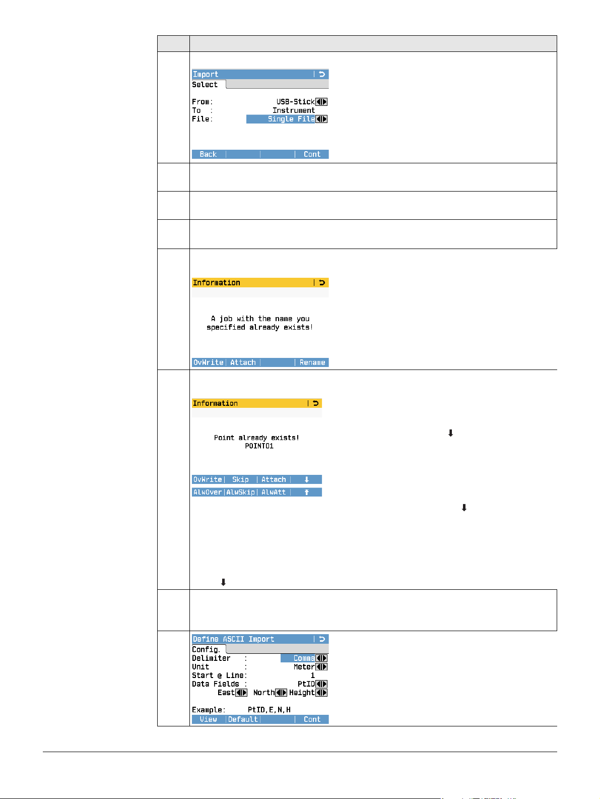
Import Data
Step-by-Step
Step Description
1. Choose the desired settings in the Import screen:
From:
USB-Stick or Internal Memory
File:
Import a single file or a backup folder.
2. Press Cont in the Import screen to proceed to the USB memory stick file direc-
tory.
3. Select the file or backup folder on the USB memory stick to be imported and
press Cont.
4. For a file:
Define the Job name for the imported file. Press Cont to import.
If a Job with the same name already exists in the internal memory, an information message is displayed:
OvWrite
To overwrite the existing job.
Attach
To attach the new points to the current job.
Rename
To rename the job.
5. If you attach new points to the current job and a point with the same point ID
already exists, the following information message is displayed:
OvWrite
To overwrite the point with the currently
displayed point ID. Press (F4) and AlwOver to
overwrite all duplicate point IDs with the new
points.
Skip
To skip the point with the currently displayed
point ID. The new point is ignored and the
existing point is kept. Press (F4) and AlwSkip
to skip all duplicate points.
Attach
To attach the new point to the current job and keep the existing point. The
existing point ID is renamed with a numerical suffix. For example, Point23 is
renamed to Point23_1. The maximum renamed suffix is 10, e.g. Point23_10.
Press (F4) and AlwAtt to attach all duplicate points to the current job.
For a backup folder:
Take note of the warning message displayed and press Cont to proceed and
import the folder.
6.
If the file is an ASCII file, the Define ASCII
Import screen is displayed. Define the delimiter
value, the units and the data fields of the file
and press Cont to continue.
LS10/LS15, Data Management
82
Page 83
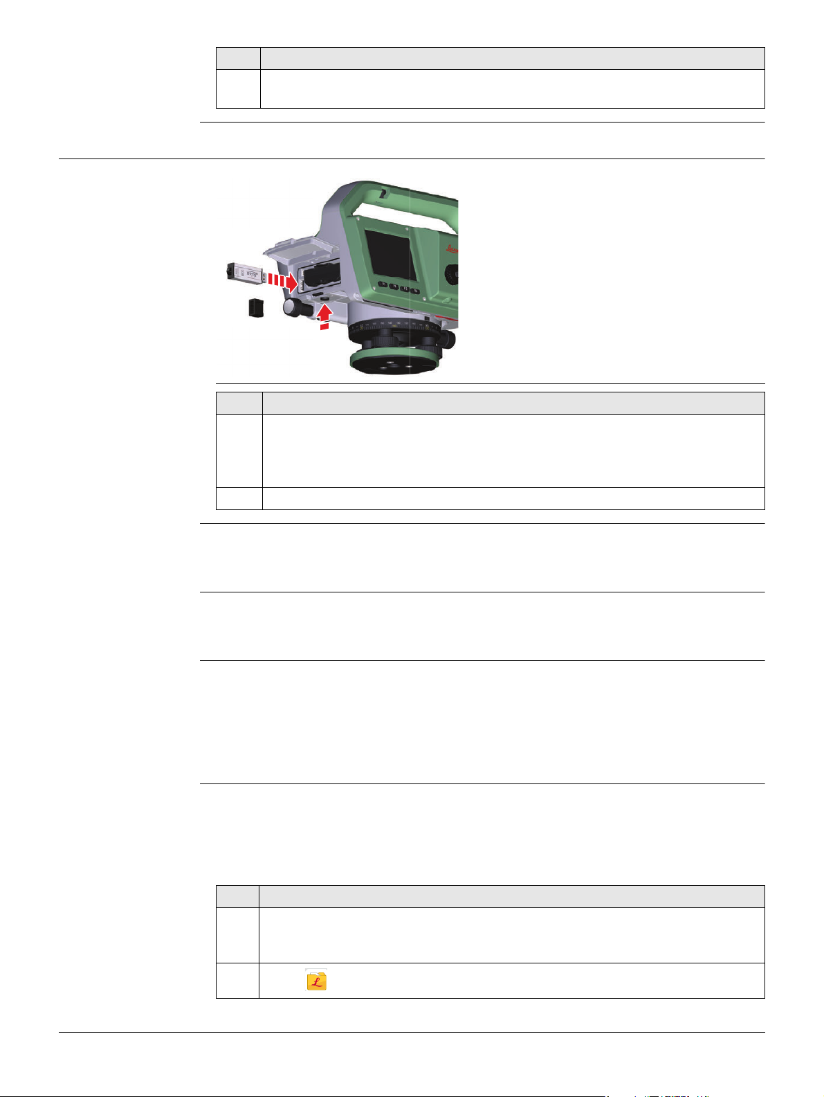
Step Description
1
2a
7. Once the file or backup folder has been successfully imported, a message is
displayed.
13.4 Working with a USB Memory Stick
Insert a
USB Memory Stick
Step-by-Step
2
1
010758_001
Step Description
1. Open the battery compartment by pressing the push button underneath the
battery compartment.
2. Insert the USB memory stick into the USB host port.
The USB host port is located at the left side of the battery compartment.
Format a USB
Memory Stick
Step-by-Step
Always return to the Main Menu before removing the USB memory stick. If you
remove the stick without returning to the Main Menu, a warning message is
displayed.
Whilst other USB memory sticks may be used, Leica Geosystems recommends Leica
industrial grade USB memory sticks and cannot be held responsible for data loss or
any other error that may occur when using a non-Leica USB memory stick.
• Keep the USB memory stick dry.
• Use it only within the specified temperature range, -40°C to +85°C (-40°F to
+185°F).
• Protect the USB memory stick from direct impacts.
Failure to follow these instructions could result in data loss and/or permanent damage
to the USB memory stick.
If you use a completely new USB memory stick or if you want to delete all existing data,
format the USB memory stick before starting to store data.
If the instrument detects a non-recommended File Allocation Table (FAT) on the USB
stick, you are automatically prompted to format the USB stick upon insert. The recommended FAT is FAT32. Follow the on-screen instructions to format with FAT32.
Step Description
1.
LS10/LS15, Data Management
Despite an automatic defragmentation, the USB memory stick gets fragmented after a while. Please format the USB memory stick periodically to maintain the instrument performance.
Select Manage from the Main Menu.
83
Page 84
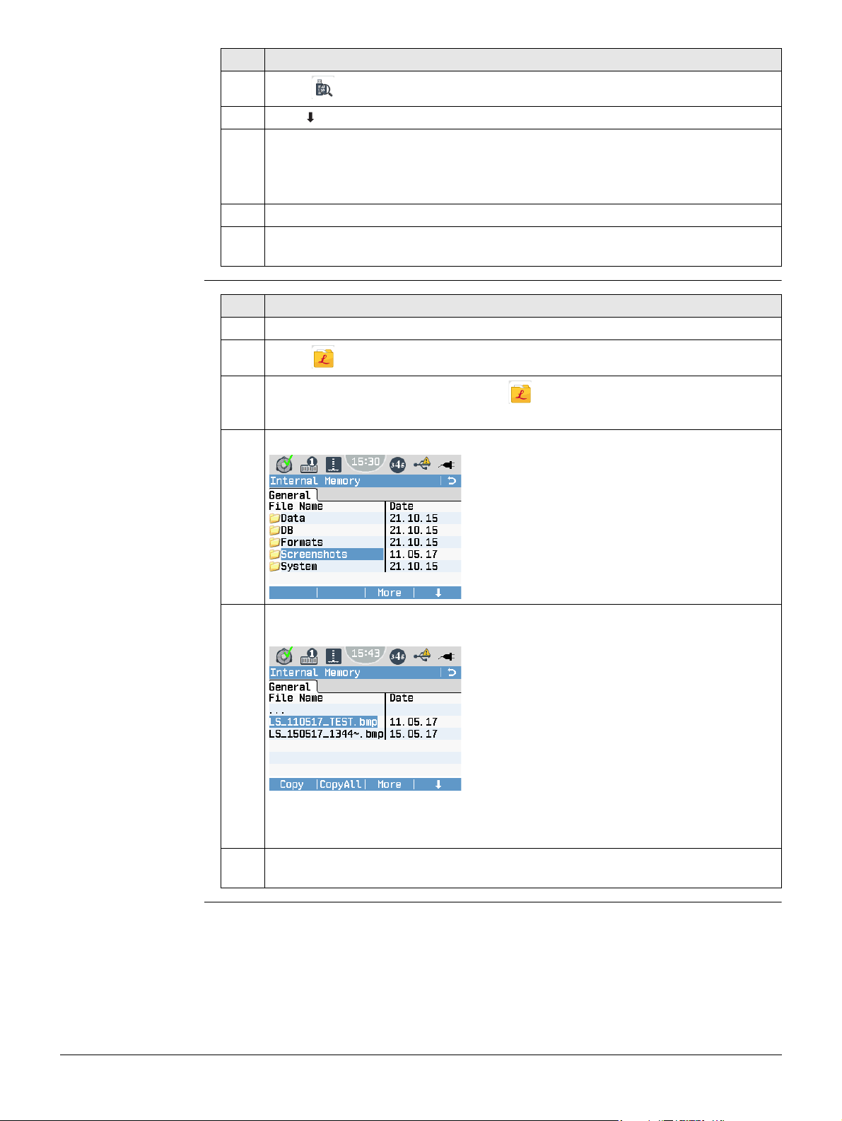
Step Description
2.
3. Press Format in the USB-File Manager screen.
4. A warning message will appear.
5. Press Yes to format the USB memory stick.
6. A message will display once the formatting of the USB memory stick is
Select USB-Stick from the Manage Menu.
completed. Press Cont to return to the USB-File Manager screen.
By activating the format command all data will be lost. Make sure that
all important data on the USB memory stick has been backed up before
formatting the USB memory stick.
Copy Screenshots
to a USB Memory
Stick Step-by-Step
Step Description
1.
2.
3. If necessary, change to the root directory. Open the folder Screenshots.
4. Once you highlight the file name of a screenshot, the softkeys Copy and
Make sure that a USB memory stick is inserted into the USB host port.
Select Manage from the Main Menu.
Switch to the second tab and select Int.Mem..
The Internal Memory screen is displayed.
CopyAll are displayed.
LS10/LS15, Data Management
• Select Copy to copy only the selected screenshot to the USB memory stick.
• Select CopyAll to copy all screenshots in the folder to the USB memory
stick.
Any existing screenshots on the USB memory stick with identical file names are
overwritten by the files from the internal memory.
84
Page 85
13.5 Working with Bluetooth
Description The LS10/LS15 can communicate with external devices via a Bluetooth connection. The
Bluetooth of the instrument is a slave module only. The Bluetooth of the external
device is the master module, and therefore controls the connection and any data
transfer.
Establishing a
Connection
Step-by-Step
Step Description
1. On the instrument ensure that the communication parameters are set to Bluetooth: and Active. Refer to "6.6 Interface Settings".
2. Activate Bluetooth on the external device. The steps required depend on the
Bluetooth driver and other device specific configurations. Refer to the device
user manual for information on how to configure and search for a Bluetooth
connection.
The instrument will appear on the external device as “LS_zzzzzz”, with zzzzzz
being the serial number of the instrument, for example LS_348005.
3. Some devices ask for the identification number of the Bluetooth. The default
number for a LS10/LS15 Bluetooth is 0000. This can be changed by:
• Select Settings from the Main Menu.
• Select Interface from the Settings Menu.
•Press BT-PIN from the Interface Settings screen.
• Enter a new Bluetooth PIN number in PIN-Code.
•Press Cont to confirm the new Bluetooth PIN.
4. When the external Bluetooth device has located the instrument for the first
time, a message will display on the instrument stating the name of the
external device and requesting confirmation that connection to this device
should be allowed.
•Press Yes to allow, or
•Press No to disallow this connection
5. The instrument Bluetooth sends out the instrument name and serial number
to the external Bluetooth device.
6. All further steps must be made in accordance to the user manual of the
external device.
13.6 Working with Leica Infinity
Description With the office software Leica Infinity, you can seamlessly import, manage and post
process level data from the LS10/LS15. The supported file types are HeXML, GSI and
LEV. To transfer the level data to Infinity, use a USB cable connection or export the
files to a USB memory stick. In Leica Infinity, level data can be combined and adjusted
together with total station- and GPS data sets.
LS10/LS15, Data Management
85
Page 86
14 Check & Adjust
14.1 Overview
Description Leica Geosystems instruments are manufactured, assembled and adjusted to the best
possible quality. Quick temperature changes, shock or stress can cause deviations and
decrease the instrument accuracy. It is therefore recommended to check and adjust
the instrument from time to time. This check and adjust can be done in the field by
running through specific measurement procedures. The procedures are guided and
must be followed carefully and precisely as described in the following chapters. Some
other instrument errors and mechanical parts can be adjusted mechanically.
Electronic
Adjustment
Mechanical
Adjustment
During the manufacturing process, the instrument errors are carefully determined and
set to zero. These errors can change and it is highly recommended to determine them
again for any of the following situations:
• Before the instrument is used for the first time.
• Before every high precision levelling task.
• After rough or long periods of transport.
• After long periods of work or storage.
• If the temperature difference between current environment and the temperature
during the last calibration is more than 10°C (18°F).
You can carry out the following electronic adjustment tasks:
• Correcting the collimation error, also called line-of-sight error (refer to "14.3
Adjusting Line-of-Sight Error").
• Aligning the camera crosshair (refer to "14.5 Aligning the Camera Crosshair").
• Calibrating the digital compass (refer to "14.6 Calibrating the Digital Compass").
• Adjusting the electronic level (refer to "14.8 Adjusting the Electronic Level").
You can adjust the following instrument parts mechanically:
• Circular level of the instrument (refer to "14.7 Adjusting the Circular Level of the
Instrument").
• Optical crosshair (refer to "14.4 Adjusting the Optical Crosshair").
• Screws on the tripod (refer to"14.9 Servicing the Tripod").
14.2 Preparation
LS10/LS15, Check & Adjust
Before starting to work, the instrument has to become acclimatised to the ambient
temperature. Approximately two minutes per °C of temperature difference from
storage to working environment, but at least 15 min, should be taken into account.
Before determining the instrument errors, level-up the instrument using
the circular level and if available, the electronic level. Ensure, that the
circular level is adjusted (refer to "14.7 Adjusting the Circular Level of the
Instrument").
The tribrach, the tripod and the ground should be very stable and secure
from vibrations or other disturbances.
During the calibration, protect the instrument and if possible also the
staffs from direct sunlight in order to avoid uneven thermal expansion on
one side only.
86
Page 87
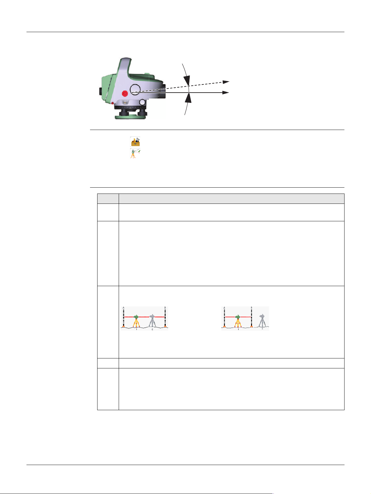
14.3 Adjusting Line-of-Sight Error
Line-of-Sight Error The line-of-sight error (collimation error) is the vertical angle () between the actual
line-of-sight and the ideal horizontal line. It is determined by a level test.
Access
Check and Adjust
Step-by-Step
009178_001
1. Select Tools from the Main Menu.
2. Select Adjust from the Tools Menu.
An information page is displayed.
Menu.
3. Select F1 Line Of Sight.
Step Description
1. Press F1 or tap on F1 Line Of Sight to start the adjustment of the collimation
error.
2.
3.
On the page
Select one of the available adjustment methods. A and B are the staffs positions, x is the instrument position. Each method covers two procedures.
• A x Bx method covers “From the Centre” procedure (classic) and
Kukkamäki procedure (refer to " Adjustment Method “A x Bx”").
• A x x B method covers Förstner and Näbauer procedure (refer to " Adjust-
ment Method “A x x B”").
Press F4 or Cont.
An information page displays the correct setup of the station according to the
selected adjustment method.
α
General
Select Cont to display the Check & Adjust-
, the current collimation error is displayed in arc seconds.
4. Press F4 or Cont.
5.
LS10/LS15, Check & Adjust
A x x B method
Set up the instrument at the first position (station 1) and level the instrument
with the electronic level.
• Aim at staff A and carry out a measurement (A1).
• Aim at staff B and carry out a measurement (B1).
• Store the measurements for station 1.
To aim at the staff, you can use the overview camera within the tab
Camera.
A x Bx method
87
Page 88
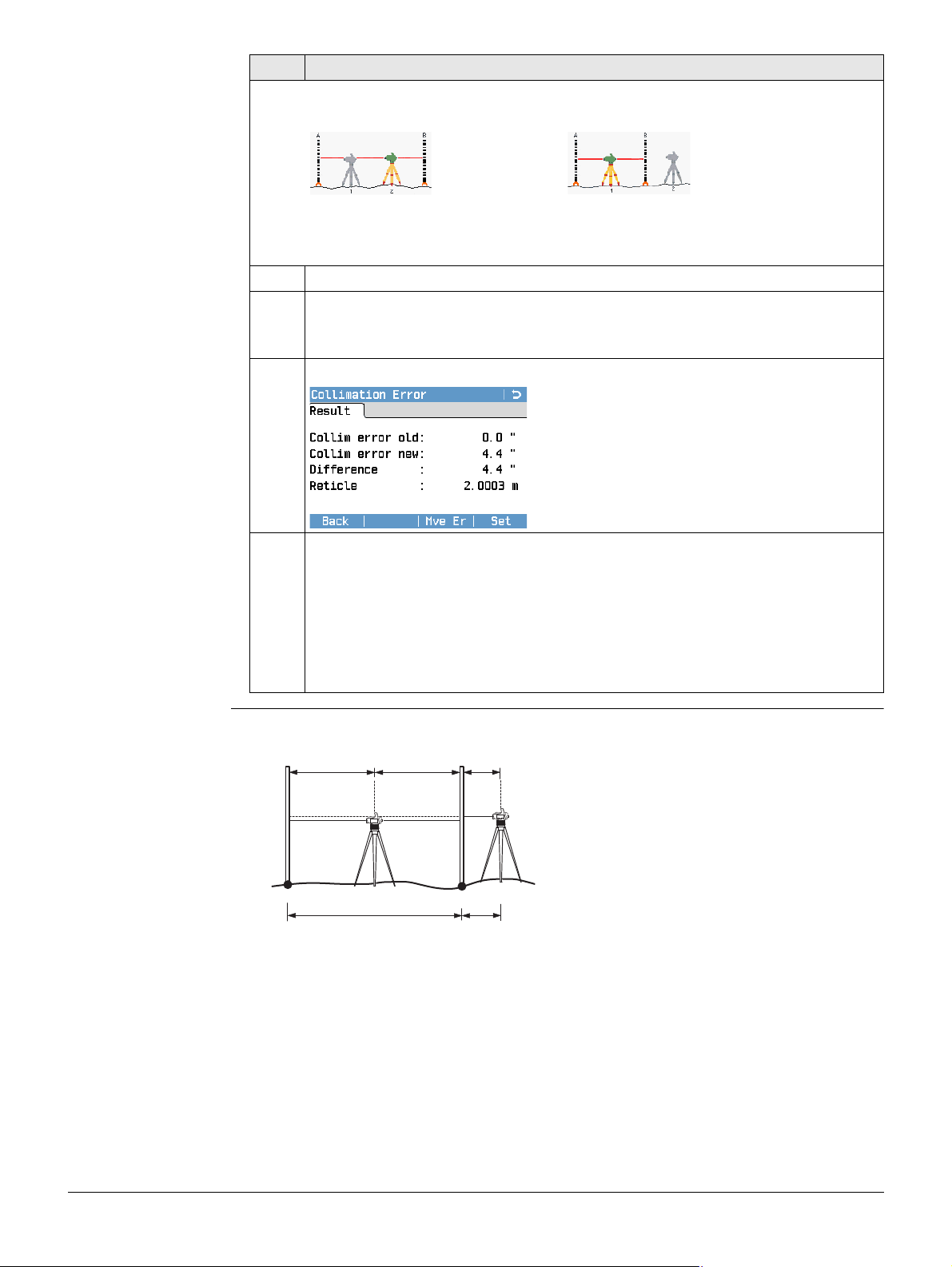
Step Description
6.
An information page displays the correct setup of the station according to the
selected adjustment method.
A x x B method
A x Bx method
Set up the instrument at the second position (station 2) and level the instrument with the electronic level.
7. Press F4 or Cont.
8. • Aim at staff B and carry out a measurement (B2).
• Aim at staff A and carry out a measurement (A2).
• Store the measurements for station 2.
On the page
Result
, the results of the adjustment procedure are displayed.
To set the determined collimation error and
apply it to all subsequent measurements,
press Set.
9.
For some markets, it may be necessary to add the determined user
collimation error to the factory collimation error. By adding the user
collimation error, the correct collimation error is applied to all measurements and the reported user collimation error is within the marketspecific tolerance.
To add the determined user collimation error to the factory collimation
error, press Mve Er. You need to confirm this action by pressing Cont.
After confirming, the new user collimation error is reported as 0.0.
Adjustment Method
“A x Bx”
“From the Centre” Procedure
009364_001
A
1/2
1/2
1
ab
B
b
2
First position (station 1):
• Position the instrument centrally between staff A and B.
• The centre has to be within an accuracy of ±1 m.
• The distance a between the staffs should be approximately 30 m.
Second position (station 2):
• Position the instrument close to staff B (inside or outside).
• The distance b has to be at least 2.5 m.
LS10/LS15, Check & Adjust
88
Page 89
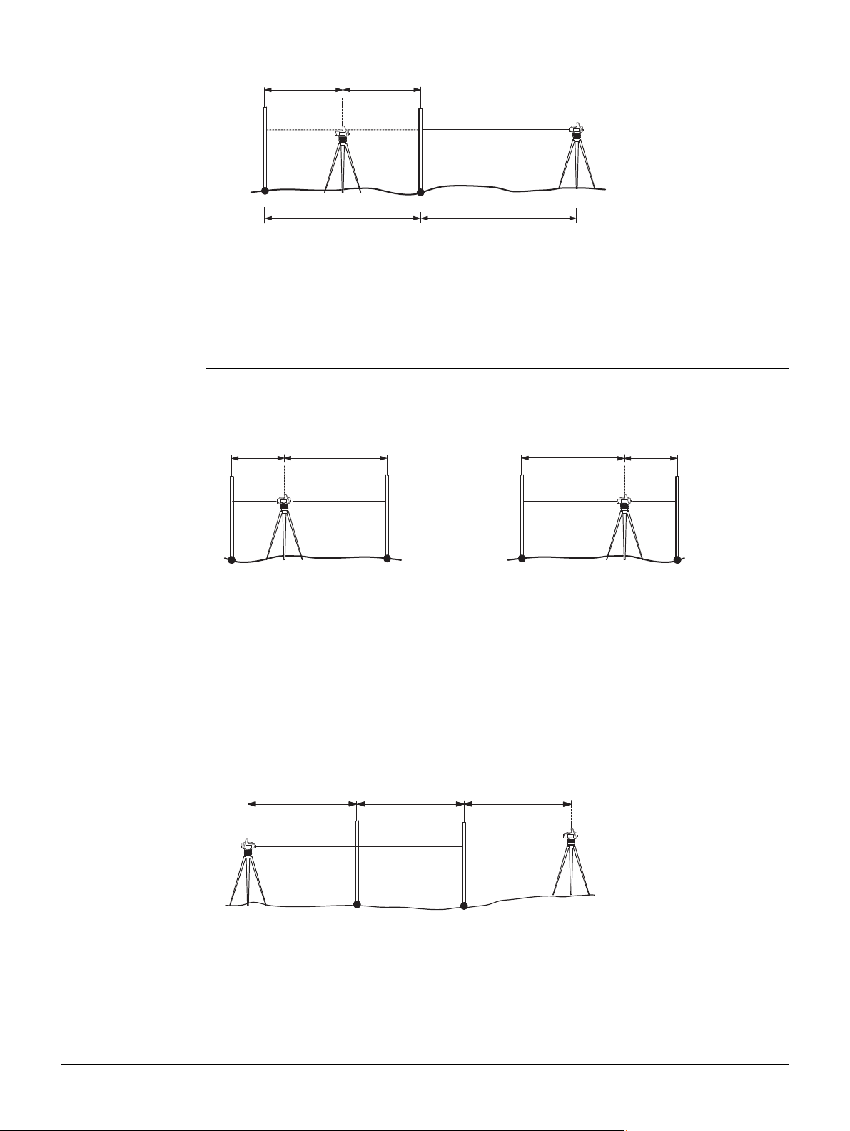
Kukkamäki Procedure
Adjustment Method
“A x x B”
AB
1/2
009365_001
1/2
1
ab
2
First position (station 1):
• Position the instrument centrally between staff A and B.
• The centre has to be within an accuracy of ±1 m.
• The distance a between the staffs should be approximately 20 m.
Second position (station 2):
• Position the instrument on the outside of staff B at the distance b (b = a).
For this adjustment method, the distances to the staffs have a 1:2 ratio for each position of the instrument.
Förstner Procedure
A
1/3
Dist_A1 Dist_B1
2/3
B
A
2/3
1/3
Dist_B2
B
1
009362_001
First position (station 1):
• Position the instrument at 1/3 of the
distance D between staff A and B.
• The distance D should be approxi-
mately 45 m - 60 m.
• The following requirement must be
fulfilled: 0.2 x D < Dist_A1 < 0.4 x D
and D=Dist_A1+Dist_B1.
Näbauer Procedure
aaa
1
009366_001
A
009363_001
2
Second position (station 2):
• Position the instrument at 2/3 of the
distance D between staff A and B.
• The following requirement must be
fulfilled: 0.2 x D < Dist_B2 < 0.4 x D
and D=Dist_A1+Dist_B1.
B
2
LS10/LS15, Check & Adjust
89
Page 90
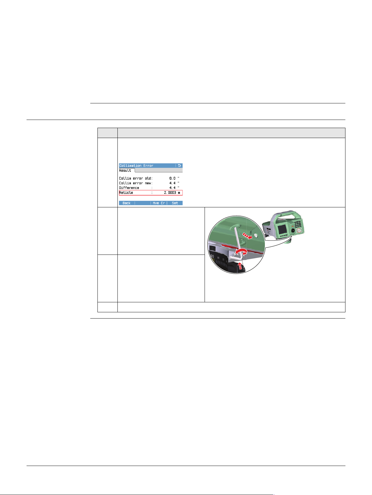
First position (station 1):
2b
2a
1
• Position the instrument on the outside of staff A at the distance a.
• The distance a should be approximately 15 m - 20 m and be equal to the distance
between staff A and B.
• The following requirement must be fulfilled: 0.2 x D < Dist_A1 < 0.4 x D and
D=Dist_A1+Dist_B1.
Second position (station 2):
• Position the instrument on the outside of staff B at the distance a.
• The following requirement must be fulfilled: 0.2 x D < Dist_B2 < 0.4 x D and
D=Dist_A1+Dist_B1.
14.4 Adjusting the Optical Crosshair
Adjust the Optical
Crosshair
Step-by-Step
Step Description
To check if the optical crosshair needs adjustment, first adjust the line-ofsight error. Pay attention to the Reticle value which is displayed in the Result
screen:
Take an optical height reading and check if this value
corresponds with the Reticle value of the Result
screen. If not, you need to adjust the optical crosshair.
1. The crosshair adjustment
screw is underneath the
eyepiece and is covered by a
protective cap. Pull out the
1
cap about 1 cm and slightly
press it to the side.
2b
2a
2a
2b
2. Using an allen key, turn the
adjustment screw to move
the optical crosshair until the
010757_001
optical height reading corresponds with the Reticle value
on the screen.
3. Gently remove the allen key and put the protective cap back in place.
LS10/LS15, Check & Adjust
90
Page 91
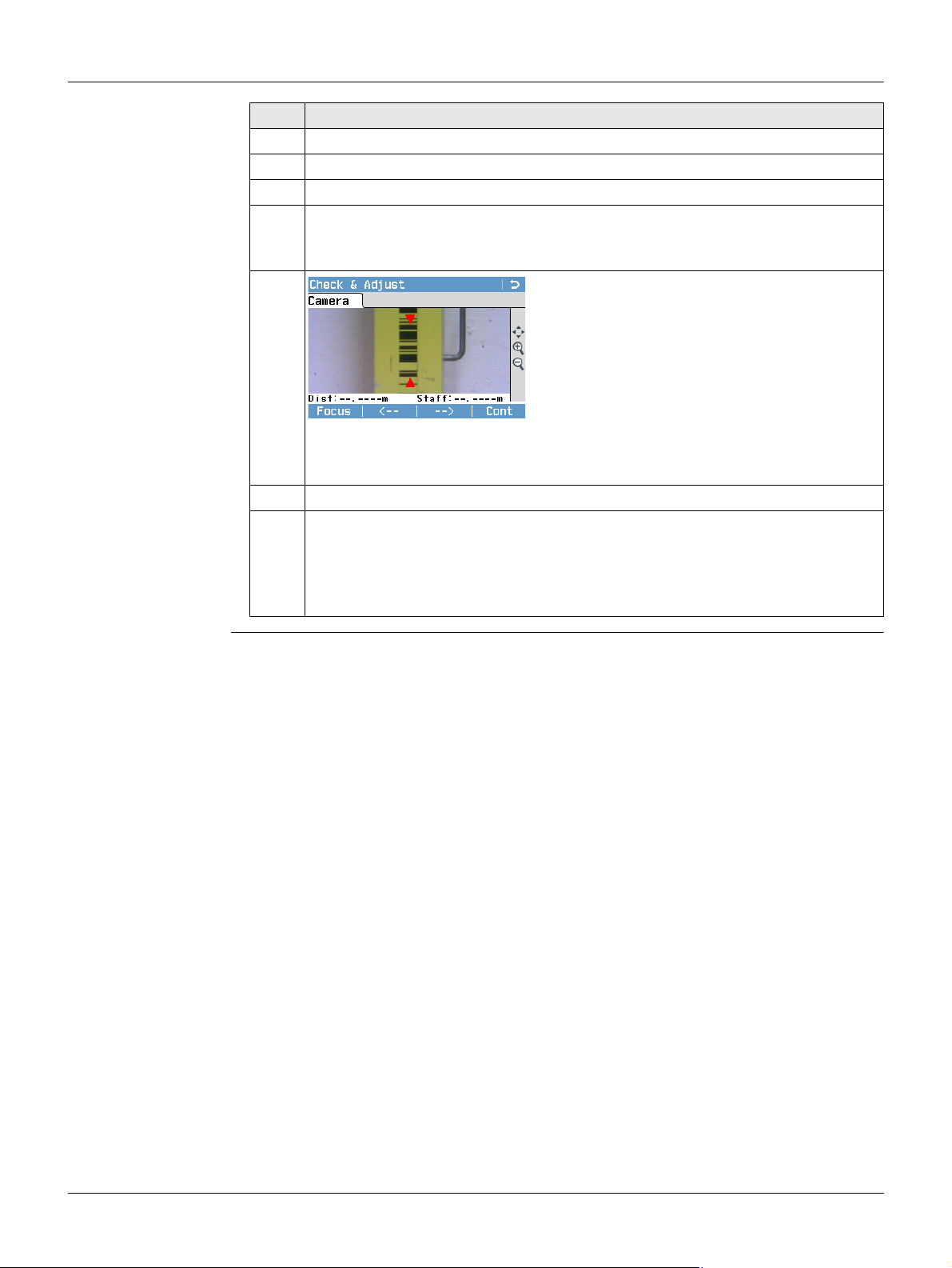
14.5 Aligning the Camera Crosshair
Only for LS15 Step-by-Step
Step Description
1. Select Tools from the Main Menu.
2. Select Adjust from the Tools Menu.
3. Select F2 Camera Crosshair from the Check & Adjust screen.
4. An information message is displayed.
Aim accurately at a vertical target by using the optical crosshair. Press the
softkey Cont (F3).
5.
6. To save the changes and display the next screen, press Cont.
An information message is displayed.
Press Cont to accept the new position of the camera crosshair and to close
the Check & Adjust screen.
Press Reset to reset the crosshair to the factory default and to return to the
Check & Adjust screen.
Focus
To focus the optics onto the staff distance.
<--
To move the camera crosshair (vertical indicators) to the left.
-->
To move the camera crosshair (vertical indicators) to the right.
The camera crosshair moves with an
increment of one pixel.
LS10/LS15, Check & Adjust
91
Page 92
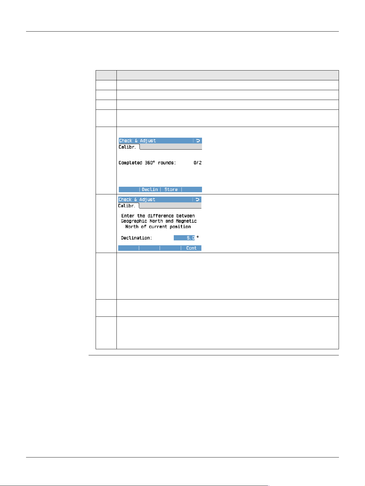
14.6 Calibrating the Digital Compass
Only for LS15 Step-by-Step
Step Description
1. Select Tools from the Main Menu.
2. Select Adjust from the Tools Menu.
3. Select F3 Digital Compass from the Check & Adjust screen.
4. Read the instruction in the displayed information message. Press the softkey
5. The following screen is displayed:
6.
For correct measurement results, it is recommended to perform a compass
calibration every time you set up the instrument. For this purpose, you can
define the compass calibration screen as start screen. Refer to "6.1 Work
Settings".
Cont (F4) to start with the compass calibration.
If it is required to enter a magnetic declination
correction for the current work location, press
the softkey Declin (F3).
Enter the declination value. To store the
entered value, press Cont (F4).
7. Rotate the instrument 360° at least two times. While rotating, the field
8. To complete the compass calibration, press Cont (F4).
Magnetic declination is the difference between geographic north and
magnetic north and changes with the location on earth and also over time.
The magnetic declination is given in degrees. A positive value indicates a declination east of north, a negative value a declination west of north. To get a
correct calibration result, you need to enter the current magnetic declination
at your position.
Completed 360° rounds displays the number of already completed rounds.
An information message is displayed to inform you whether the compass calibration has been successful. To confirm the information message, press Cont
(F4).
LS10/LS15, Check & Adjust
92
Page 93
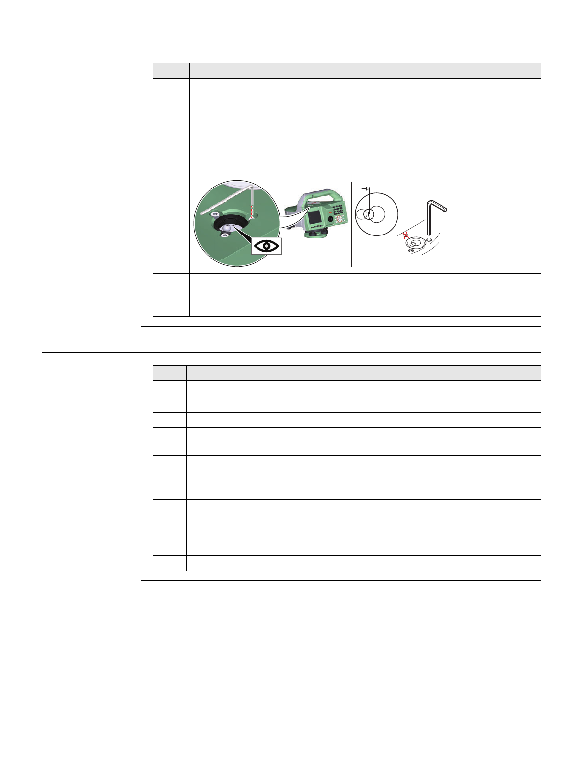
14.7 Adjusting the Circular Level of the Instrument
Adjust the Circular
Level Step-by-Step
Step Description
1. Place and secure the instrument onto the tribrach.
2. Using the tribrach footscrews, level the instrument with the circular level.
3. Turn the instrument by 180°/200 gon and observe the bubble of the circular
level.
If after turning, the bubble is still centred no adjustment is needed.
4. If the bubble is not centred, correct half of the deviation by moving the
adjustment screws with the supplied allen key.
010754_001
5. Turn the instrument again by 180°/200 gon and observe the bubble.
6. If necessary, repeat the two previous steps until the bubble is centred
correctly.
14.8 Adjusting the Electronic Level
Step-by-Step
Step Description
1. Select Tools from the Main Menu.
2. Select Adjust from the Tools Menu.
3. Select F4 Level Bubble from the Check & Adjust screen.
4. Use the mechanical circular level to precisely level the instrument. Press the
softkey Cont (F4).
5. Turn the horizontal circle of the instrument to 0 gon/0 deg.
6. Press the trigger key and wait until the next screen is displayed.
7. Turn the horizontal circle of the instrument to 200 gon/180 deg.
8. Press the trigger key and wait until the message “Level Bubble calibrated!“
is displayed.
Press the softkey Cont (F4) to return to the Main Menu.
Avoid any vibrations while turning the instrument.
Avoid any vibrations while turning the instrument.
LS10/LS15, Check & Adjust
93
Page 94
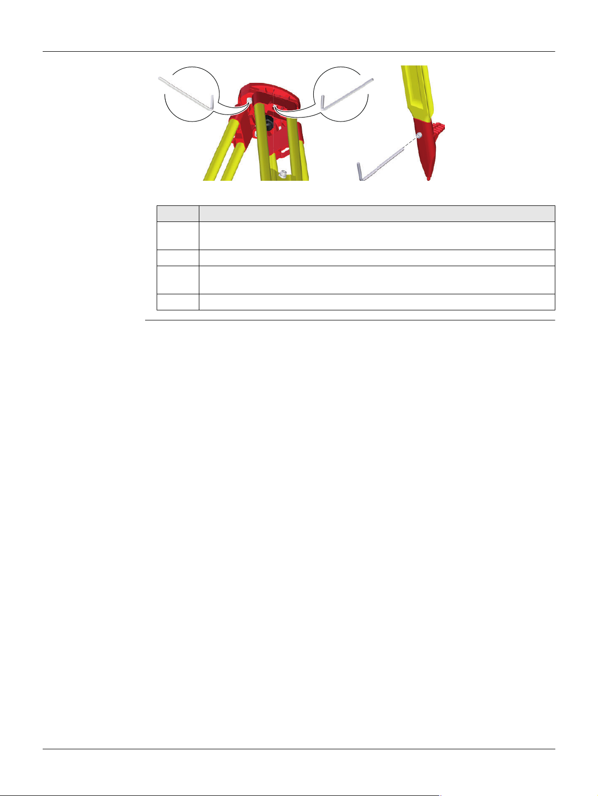
14.9 Servicing the Tripod
Servicing the Tripod
Step-by-Step
2
008706_001
The following table explains the most common settings.
Step Description
1. Tighten the leg cap screws moderately, with the supplied allen key.
2. Tighten the articulated joints on the tripod head enough to keep the tripod
3. Tighten the allen screws of the tripod legs.
The connections between metal and timber components must always be
firm and tight.
legs open when lifting the tripod off the ground.
1
3
LS10/LS15, Check & Adjust
94
Page 95
15 mySecurity
Description mySecurity is a cloud-based theft protection. A locking mechanism ensures that the
instrument is disabled and can no longer be used. A Leica Geosystems service centre
will inform local authorities if such an instrument turns up.
mySecurity is activated in myWorld.
Adding/removing
instruments
to/from mySecurity
Activating the theft
protection
Step Description
1. Go to myWorld@Leica Geosystems (https://myworld.leica-geosys-
tems.com).
2. Select myTrustedServices/mySecurity.
3. Click Add to add an instrument to mySecurity.
4. Select an instrument.
For an active theft protection, the instrument must be connected to myWorld within
a defined time interval.
If the instrument is not connected within the defined interval, then the instrument is
blocked and cannot be used. In this case, the instrument must be connected to
myWorld again and the theft protection must be reactivated.
You must add your instruments to myProducts first, before the instruments can be added to mySecurity.
Available information for listed instruments:
• Activation date of the mySecurity service
• Renewal date of the mySecurity service
• Stolen status, in case of the instrument has been flagged as stolen
Select the instrument from the selectable list.
Click OK.
Click Remove to delete the instrument from mySecurity.
Step Description
1. Click the check box to select an instrument.
2. Click Details.
3. For New mySecurity Renewal, set the start date of the theft protection.
Click In 3 months, In 6 months or In 12 months to define the connection
interval.
4. Click Set.
5. Download and install the mySecurity Online Update program.
6. The program scans for the instrument connection port automatically.
In case automatic scanning fails, click Scan for a search of the port.
Select the connection settings.
7. Click Connect.
After the activation, the end date of the theft protection is displayed in the
mySecurity Online Update program and on the instrument.
8. Press Close.
9. Click the Refresh button to update the screen information.
10. Check the status, the activation date and the renewal date of the theft
protection.
LS10/LS15, mySecurity
95
Page 96
Status information
on the instrument
Step Description
1.
2. Select Info from the Tools Menu.
3. Go to page 4/4 or Dates.
4. mySec.Renewal Date:
Select Tools from the Main Menu.
Displays the date when the instrument must be connected to mySecurity.
The date is transferred from myWorld to the instrument.
Ten days before the mySec.Renewal Date, a reminder message is displayed
each time the instrument is turned on.
When the mySec.Renewal Date has been exceeded, a message informs
about the instrument lock. Go to myWorld to renew the theft protection.
Report stolen
instrument
Locate stolen
instrument
Step Description
1. Go to myWorld@Leica Geosystems (https://myworld.leica-geosys-
tems.com).
2. Select myTrustedServices/mySecurity.
3. Click the check box to select an instrument.
4. Click Details.
5. In the General section, click Report as Stolen.
6. A warning comes up to confirm device as stolen.
Click OK.
7. The Status of the instrument changes to Stolen!.
A Leica Geosystems service centre informs local authorities if such an instrument turns up.
If a reported, stolen instrument is registered to myWorld, then the IP address of the
computer is logged. The IP address is used to locate the instrument.
In myWorld/myTrustedServices/mySecurity, the Status of the instrument changes
to Located.
Clicking Show Location shows:
• The date and time when the instrument was located
• The IP address of the computer
• A link to show the location on a map
LS10/LS15, mySecurity
96
Page 97

16 Care and Transport
16.1 Care
Field adjustment Periodically carry out test measurements and perform the field adjustments indicated
Despite an automatic defragmentation, the memory gets fragmented after a while.
Please format the internal memory periodically to maintain the instrument performance.
in the User Manual, particularly after the product has been dropped, stored for long
periods or transported.
16.2 Transport
Transport in the
field
Transport in a road
vehicle
Shipping When transporting the product by rail, air or sea, always use the complete original
When transporting the equipment in the field, always make sure that you
• either carry the product in its original container,
• or carry the tripod with its legs splayed across your shoulder, keeping the attached
product upright.
Never carry the product loose in a road vehicle, as it can be affected by shock and
vibration. Always carry the product in its container, original packaging or equivalent
and secure it.
Leica Geosystems packaging, container and cardboard box, or its equivalent, to
protect against shock and vibration.
Shipping, transport
of batteries
When transporting or shipping batteries, the person responsible for the product must
ensure that the applicable national and international rules and regulations are
observed. Before transportation or shipping, contact your local passenger or freight
transport company.
16.3 Storage
Product Respect the temperature limits when storing the equipment, particularly in summer if
the equipment is inside a vehicle. Refer to "17 Technical Data" for information about
temperature limits.
Li-Ion batteries • Refer to "Technical Data" for information about storage temperature range.
• Remove batteries from the product and the charger before storing.
• After storage recharge batteries before using.
• Protect batteries from damp and wetness. Wet or damp batteries must be dried
before storing or use.
• A storage temperature range of 0 °C to +30 °C / +32 °F to +86 °F in a dry environment is recommended to minimize self-discharging of the battery.
• At the recommended storage temperature range, batteries containing a 40% to
50% charge can be stored for up to one year. After this storage period the batteries
must be recharged.
Charger and docking
station
• Keep chargers and docking stations away from excessive dirt, dust and contaminants.
• After unpacking the product visually inspect the charger for possible damage.
• Unplug the product from the outlet before attempting any maintenance or
cleaning.
LS10/LS15, Care and Transport
97
Page 98
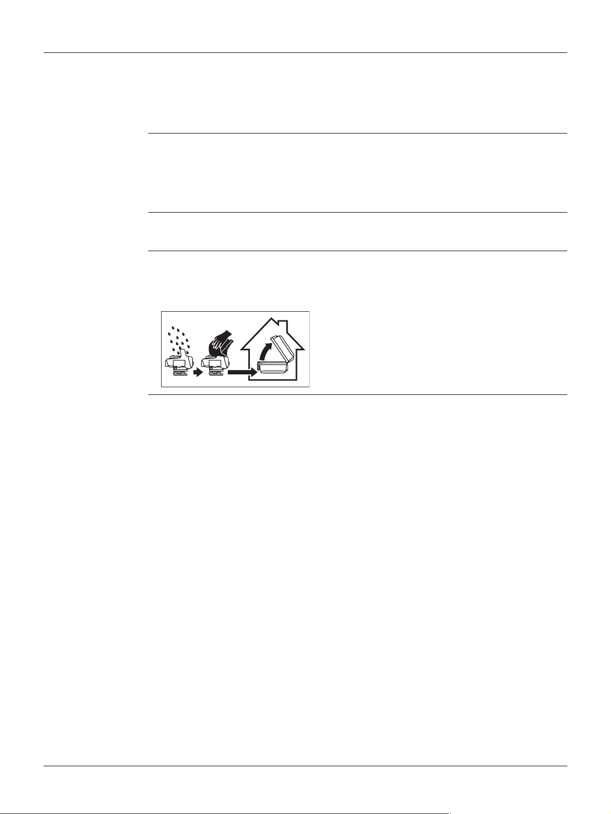
16.4 Cleaning and Drying
NOTICE
Product and
Accessories
Cables and plugs Keep plugs clean and dry. Blow away any dirt lodged in the plugs of the connecting
Damp Products Dry the product, the transport container, the foam inserts and the accessories at a
Cleaning of all optical parts requires great care. Improper cleaning can destroy optical
surfaces which may lead to a malfunction.
Precautions:
Only use appropriate cleaning material and follow the cleaning procedure described in
this User Manual.
• Use only a clean, soft, lint-free cloth for cleaning. If necessary, moisten the cloth
with water or soapy water. Do not use other liquids; these may attack the product
surface.
For power supplies and chargers:
• Use only a clean, soft, lint-free cloth for cleaning.
cables.
temperature not greater than 40°C /104°F and clean them. Open and dry the battery
compartment. Do not repack until everything is completely dry. Always close the transport container when using in the field.
LS10/LS15, Care and Transport
98
Page 99
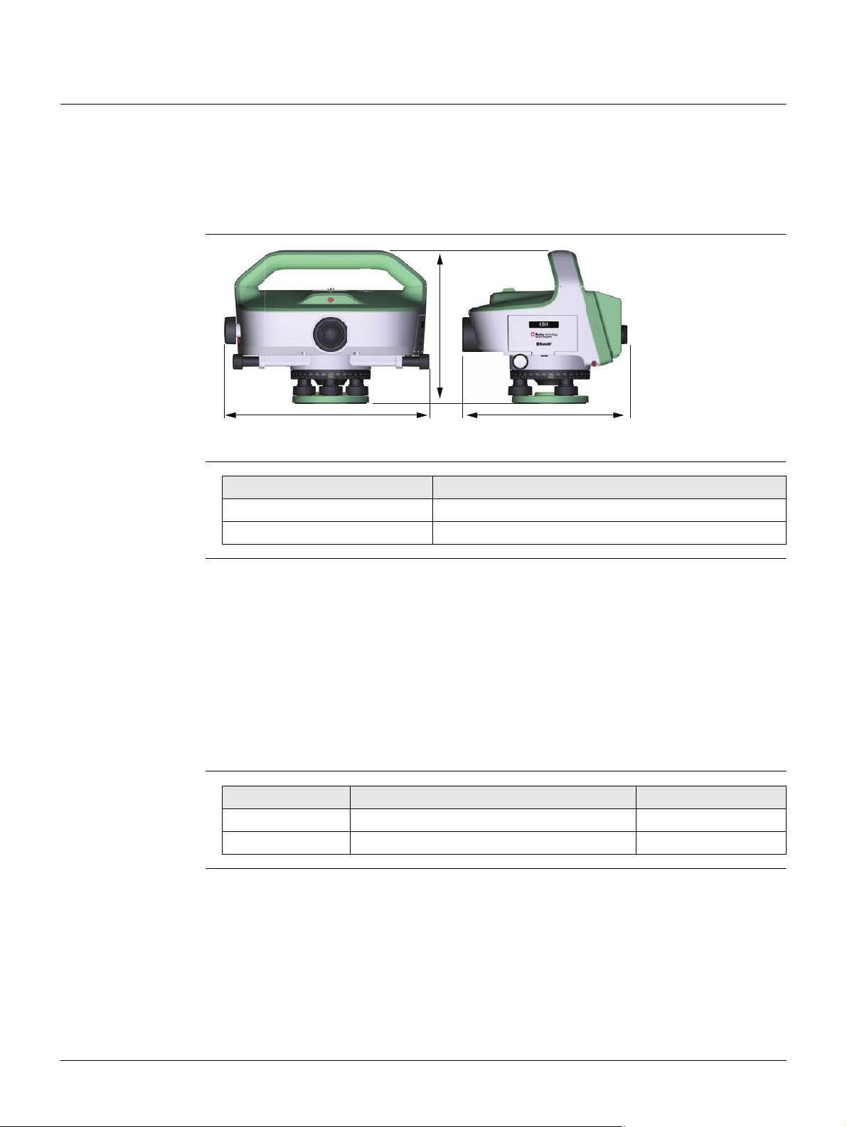
17 Technical Data
17.1 General Technical Data of the Instrument
Control Unit Display
LCD display: QVGA (320 x 240 pixels) colour touch screen; bright-
ness of backlight LED is adjustable.
Keyboard
28 Keys: including 4 Function keys and 12 alphanumeric keys
Instrument Dimensions
206 mm
276 mm 222 mm
Weight
010755_001
Instrument type Weight (including GEB331 battery)
LS10 3.7 kg/8.2 lbs
LS15 3.9 kg/8.6 lbs
Power Supply External Power Supply using the Serial Interface
Voltage: Nominal voltage 12.8 V DC
Range 10.5 V-18 V
Standby power consumption: Typically 1.4 W
Operating power consumption: Typically 2 W (3 W when motor for Autofocus is in use)
Internal Battery GEB331
Type: Li-Ion
Voltage 11.1 V
Capacity: 2.8 Ah
Operating time: 10-12 h
Data Storage
Type Capacity / Number of measurements Format
Internal memory 30’000 measurements Database
USB Stick 1 GB, up to 32 GB supported ASCII
LS10/LS15, Technical Data
99
Page 100
Environmental
Specifications
Temperature
LS10 LS15 GEB331
Operating temperature [C°] -20 to +50 -20 to +50 -30 to +60
Storage temperature [C°] -40 to +70 -40 to +70 -40 to +70
Protection against Water, Dust and Sand
LS10, LS15
Protection IP55 (IEC60529)
Humidity
LS10, LS15
Protection Up to 95%
To avoid the effects of condensation, periodically dry out the instrument.
Magnetic Field Sensitivity
LS10, LS15
Line-of-sight difference in horizontal constant magnetic field
at a field strength of 0 T up to ±400 T [4 Gauss].
1
Telescope
Compensator Magnetically damped pendulum compensator with electronic range control.
Circular Level
Electronic Level
Magnification: 32x
Free objective diameter 36 mm
Opening angle 2°
Field of view 3.5 m at 100 m
Minimum target distance 0.6 m
Distance measurement with Stadia lines
Multiplication constant 100
LS10, LS15
Slope angle ±9’
Standard deviation 0.3
Sensitivity: 8’/2 mm
Working range: LS10 0.166 gon/0.150°
LS15
(Longitudinal, Transversal)
Accuracy: LS10, LS15 0.015 gon/0.013°
0.110 gon/0.099°
0.166 gon/0.150°, if Tilt Check is Off.
Autofocus
(only LS15)
LS10/LS15, Technical Data
Working range: 1.8 m to infinity
Time to focus: typically 4 s
100
 Loading...