

Page 1
TPS - System 1000
Programs
Version 2.2
English
TCA 1800
1000Z01
USER'S MANUAL
Page 2
Congratulations on your purchase of your programs
for a TPS - System 1000 !
In order to use the software correctly and reliably, you
must follow the instructions given in the user manual or
in the on-line help system. You must also adhere to the
directions given in the user manual for the product with
which you are using the software.
The rights and responsibilities accruing in respect to
Leica as a result of acquisition of the software are set
out in the Leica Software License Agreement.
T o secure your rights with regard to the software
acquired, it is essential that you follow the directions
given on the Leica Software - Support Registration
Card.
2 TPS-System 1000 Programs-2.3.1en © Leica
Page 3

TPS - System 1000
Programs
Product identification
© Leica TPS-System 1000 Programs-2.3.1en 3
Enter your programs' version number in your manual
and always refer to this information when you need to
contact your agency or authorized service workshop.
Version number:
Page 4

Symbols used in this Manual
The symbols used in this User's Manual have the
following meanings:
DANGER :
Indicates an imminently hazardous situation which, if
not avoided, will result in death or serious injury.
WARNING :
Indicates a potentially hazardous situation or an
unintended use which, if not avoided, could result in
death or serious injury.
CAUTION :
Indicates a potentially hazardous situation or an
unintended use which, if not avoided, may result in
minor or moderate injury and / or appreciable material,
financial and environmental damage.
Important paragraphs which must be adhered to in
practice as they enable the product to be used in a
technically correct and efficient manner .
4 TPS-System 1000 Programs-2.3.1en © Leica
Page 5

View of chapters
Contents 6
Introduction 11
General notes 23
Orientation and Height T ransfer 27
Resection 39
Tie Distance 49
Stakeout 59
Free Station 79
Reference Line 93
Remote Height 105
Hidden Point 111
Area (Computation of Area) 117
Sets of Angles 129
Traverse 147
CO
IN
GN
OH
RE
TD
SO
FS
RL
RH
HP
AR
SA
TR
Local Resection 165
Road Line 171
COGO 205
Road Plus 249
File Editor 303
Monitoring 333
Index 341
© Leica TPS-System 1000 Programs-2.3.1en 5
LR
RO
CG
RP
FE
MO
IX
Page 6

Contents
CO
Introduction 11
General 11
Installation in the PC 12
Hardware and software required 12
Rules for naming files 15
Loading files into the TPS1000 instruments 17
Loading system texts 19
Loading application programs 20
Licence code 21
Solving problems 21
General notes 23
Units in this manual 23
Preparation 23
Settings 23
Data exchange 24
Using the program 24
Instrument field setup 24
Calling up the program 25
Designation of keys 26
T arget eccentricity 26
Orientation and Height T ransfer 27
Introduction 27
T ar get Point 28
Point List 2 9
Measure Mode 30
Calculation 31
More Information 32
Plot 34
Configuration 35
Configuration Editor 3 5
Dual-face Measurement 37
Log file 37
Resection 39
Introduction 39
Station Data 40
T ar get Point 41
Measure Mode 42
Calculation 43
Configuration 45
Configuration Editor 4 5
Dual-face Measurement 47
Log File 47
6 TPS-System 1000 Programs-2.3.1en © Leica
Page 7

Tie Distance 49
Introduction 49
Measure Mode 51
Results 53
Configuration 55
Configuration Editor 55
Dual-face Measurement 56
Log File 57
Stakeout 59
Introduction 59
Search Point 59
Coarse Positioning 60
Line Offset 60
Orthogonal 62
Azimuth and Distance 64
Stakeout 66
Polar Stakeout 66
Orthogonal Stakeout 68
Stakeout with auxiliary points 70
Stakeout from Coordinate Differences 72
Select Stakeout Method 74
Plot 75
Configuration 76
Log File 77
Free Station 79
Introduction 79
Station Data 80
T ar get Point 80
Point List 8 1
Measure Mode 82
Calculation 83
More Information 85
Plot 87
Configuration 88
Configuration Editor 88
Dual-face Measurement 90
Log File 90
Reference Line 93
Introduction 93
Baseline Points 95
Determine Base Points 95
Measure a Base Point 96
Define Reference Line 98
Results Reference Line 99
Configuration 101
Configuration Editor 101
Log File 103
CO
© Leica TPS-System 1000 Programs-2.3.1en 7
Page 8

CO
Remote Height 105
Introduction 105
Measure Base Point 106
Measure Remote Point 108
Configuration 110
Hidden Point 1 11
Introduction 111
Configuration 112
Measure Rod 114
Results 115
Area (Computation of Area) 117
Introduction 117
Measure Mode 118
Straight line 118
Arcs 120
Calculation 123
Plot 124
Configuration 125
Configuration Editor 125
Dual-face Measurement 126
Log File 127
Sets of Angles 129
Introduction 129
Sets Menu 130
Sets menu - view 130
Measure Mode 131
Calculate Mode 135
Examples and used formulae 140
Configuration 143
Configuration Editor 143
Log File 145
Traverse 147
Introduction 147
Traverse Menu 148
Traverse menu 148
New traverse 149
Occupy station 153
Traverse Point / Sideshot Point 155
Close traverse 156
Plot 159
Configuration 160
Configuration Editor 160
Dual-face Measurement 161
Multiple Measurement 161
Log File 163
8 TPS-System 1000 Programs-2.3.1en © Leica
Page 9

Local Resection 165
Introduction 165
Station Data 166
T ar get Points 167
Calculation 168
Configuration 169
Configuration Editor 169
Dual-face Measurement 170
Road line 171
Introduction 171
Program concept 174
Alignment 175
Selection of files 175
Checking files 176
Program flow 178
Chainage and centre-line offset 178
Cross sections 180
Stakeout 183
X-section Check 184
Configuration 188
Configuration Editor 188
Log File 190
Data format 192
Hz-alignment 192
The Road - Data Entry program 204
COGO 205
Introduction 205
Configuration 207
Function selection (COGO Menu) 208
Inverse (polar calculation) 209
Traverse 212
Defining direction by magnetic bearing 214
Defining direction by Azimuth 216
Defining horizontal distance 218
Intersections 221
Bearing-Bearing Intersection 222
Bearing-Distance Intersection 227
Distance-Distance Intersection 233
Offsets 237
Distance-Offset 238
Orthogonal point calculation 241
Three Point Arc 246
Road Plus 249
Introduction 249
Alignment Definition 249
Data Files 249
Creating Data Files 252
Program Overview 252
CO
© Leica TPS-System 1000 Programs-2.3.1en 9
Page 10

CO
Getting Started 253
Configuration 254
Select Alignment Files 256
Vertical Alignment File 257
Horizontal Alignment File 257
Cross Section/template File 257
Cross Section Assignment File 259
Station Equation File 262
File Checking 263
Stakeout Using Horizontal Offset 264
Preparing for the example 264
Select T emplate point and offset 270
Stakeout and Record point 273
Horizontal Offset Stake Out Summary 280
Start ROADPLUS & Set Configuration Options 280
Select Alignment Files 281
Set offset value and select point to stakeout 282
Stakeout the point 283
Select new chainage 284
Slope Staking 285
Reference Point 289
Data Formats 291
Horizontal Alignment 291
V ertical Alignment 294
Cross Sections 296
Cross Section Assignments 298
Station Equations 300
Log File 301
File Editor 303
Introduction 303
Creation of files 303
Editing files 304
Open file 305
Coordinates 306
Horizontal Alignment 311
V ertical Alignment 317
Template 321
Station Equation 325
Cross-section Assignment 329
Monitoring 333
Main menu 335
Selecting points 336
Measurement menu 337
Selecting the points to be measured 338
Timer selection 339
Point measurement 340
End monitoring 340
Index 341
10 TPS-System 1000 Programs-2.3.1en © Leica
Page 11

Introduction
General
The electronic theodolites and total stations in the TPS
System 1000 are equipped with programs for
processing field data and control-point coordinates. The
systems are therefore highly functional and classical
survey tasks are simplified appreciably.
When delivered, the instruments are already equipped
for the following standard applications:
- Orientation and height transfer
- Resection
- Tie distance
- Stakeout
- Free-station survey (Licence code required)
In addition, the following applications are delivered on
diskette:
- Reference line / building alignment
- Remote height
- Hidden points
- Computation of area
- Sets of angles
- Traverse
- Local resection
- Roadline
- File Editor
- Road Plus
- COGO
- Monitoring
IN
This list is extended continuously. Find actual
information in file README.TXT on diskette.
The additional application programs can be loaded into
the instrument, but can only be run as a demonstration
version in which certain functions are disabled. Full
functionality can be obtained with a licence code,
available from your Leica agency, where you can also
obtain information about the newest programs available
in the ongoing applications-software development
© Leica TPS-System 1000 Programs-2.3.1en 11
Page 12

project.
All installation programs and applications are supplied
on normal 3 1/2" diskettes.
IN
Installation in the PC
Hardware and software required
For optimal use of the programs and instruments read
this manual carefully.
The hardware and software used to transfer the
individual program packages must meet the following
requirements:
• IBM-compatible PC, 386 or higher
• 4 MB RAM
• 3.5" floppy-disk drive
• RS 232 interface, including interface cable for Leica
survey instruments (stock no. 563625)
• MS DOS 5.0 or higher
• MS Windows 3.1
Four diskettes are supplied with each instrument:
• disk 1 = SYSTEM FIRMWARE
• disk 2 = Programs and Languages
• disk 3 = TPS-WORKBENCH
• disk 4 = RCS 1000
More information can be found in the file
README.TXT on each diskette.
Recommended installation procedure:
1. TPS-WORKBENCH (disk 3)
2. SYSTEM FIRMWARE (disk 1)
3. Programs and languages (disk 2)
4. RCS 1000 (disk 4)
12 TPS-System 1000 Programs-2.3.1en © Leica
Page 13
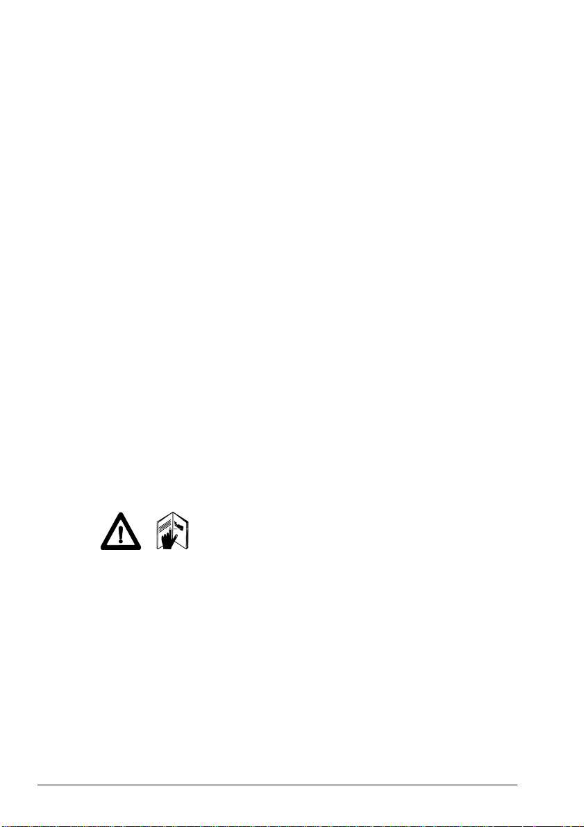
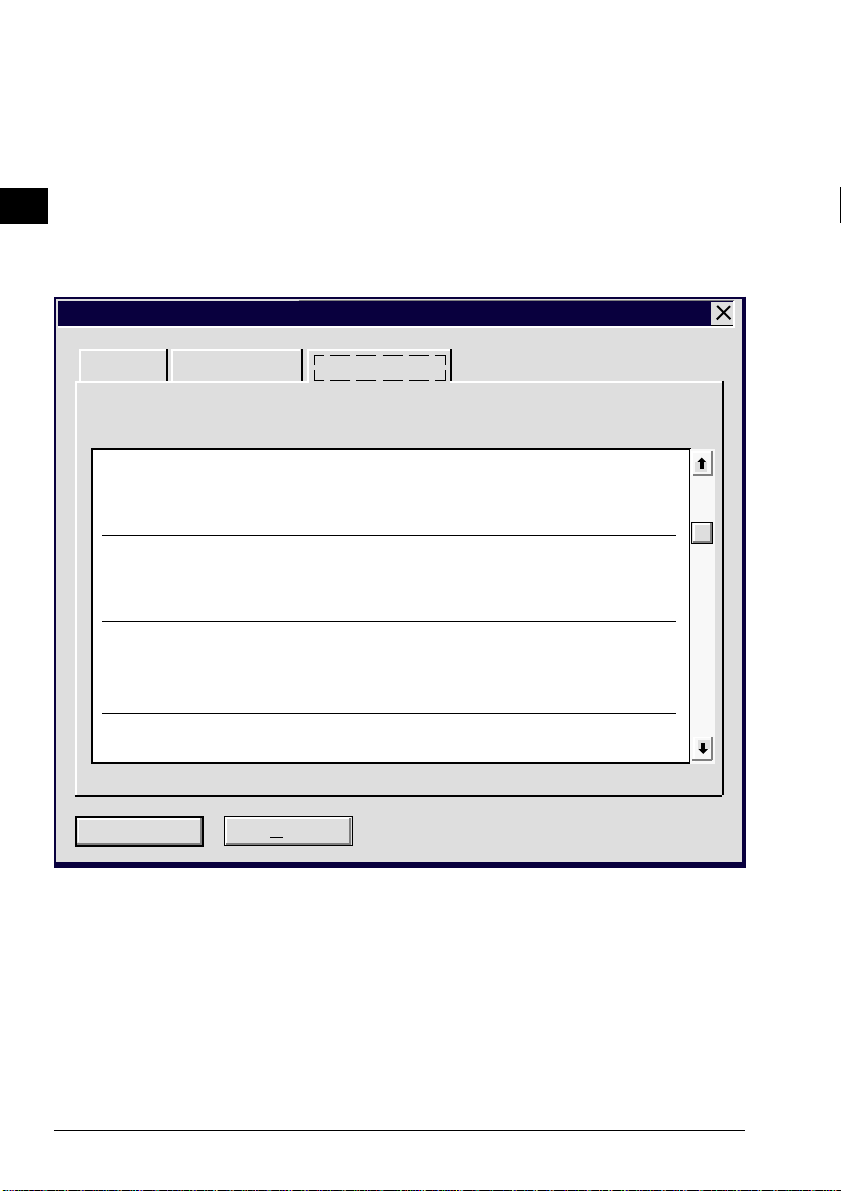
On the diskette bearing the label
TPS 1000/2000/5000
TPS-WORKBENCH
is the PC software needed to install applications or
foreign-language texts on the TPS1000 instruments.
Workbench TPS Tools 2.21
Installation
Installation TPS
Install to:
C:\LEICA.WB
Installation Options:
ü
TPS Software Upload 378 KB
ü
RCS 1000 Controller Upload 57 KB
ü
TPS Code Development 157 KB
ü
Software Radio Configuration 123 KB
ü
TPS PC to MC / MC to PC 277 KB
Installation Drive: C:
Space Required: 1697 KB
Space Available: ...... KB
IN
Continue
Exit
Directory...
Pause
Exit F3
The "WORKBENCH" program is installed in the PC by running the program "SETUP.EXE" under WINDOWS on the diskette. For further details, refer to the handbook or to the HELP file of WINDOWS.
TPS-user just have to install the "TPS Softwae
Upload".
© Leica TPS-System 1000 Programs-2.3.1en 13
Page 14

IN
The diskette bearing the label
TPS 1000
SYSTEM FIRMWARE
contains the necessary system software for the TPS
1000 instrument:
• theodolite system software
• A TR system software
• EDM system software
The diskette bearing the label
TPS 2000/5000
SYSTEM FIRMWARE
contains the necessary system software for the
TPS2000/5000 instrument:
• theodolite system software
• A TR system software
• EDM system software
The diskette bearing the label
TPS 1000/2000/5000
Programs and Languages
contains:
• all applications (both the standard ones and the
additional ones),
• the appropriate text files for the languages available.
The text for the languages available are also included
for the TPS1000 system software.
The diskette bearing the label
TPS 1000/2000/5000
RCS 1000
contains the remote control software:
• for RCS 1000 based on CR233/333
• for RCS 1000 based on GPC1
14 TPS-System 1000 Programs-2.3.1en © Leica
Page 15

Rules for naming files
The files are named in accordance with the following
rules:
Application programs: ?????VVV.PRG
????? Maximum of 5 characters for name of
application
VVV 3 characters for version (release) number
PRG Identification tag for loadable application
Text files: ?????VVV .LSS
????? identical name of relevant application
VVV identical version (release) number of relevant
application
L Identification tag for text file of application
SS Identification tag for language
SS => EN English
GE German
FR French
SP Spanish
System texts:SYS?_VVV._SS
SYS?_ Seven text files (SYS1_ ... SYS7_)
VVV Version (release) number of system texts
Identification tag for text file of system
SS Identification tag for language
SS => GE German
FR French
SP Spanish
IN
© Leica TPS-System 1000 Programs-2.3.1en 15
Page 16

After the installation is complete, you will find the
following files in the subdirectory in your PC:
Standard applications
IN
Application File name Text file Remarks
All prtxtVVV.LEN
prtxtVVV.LGE
prtxtVVV.LFR
prtxtVVV.LSP
Orientation and
height transfer
ORI__VVV.PRG ORI__VVV.LEN
ORI__VVV.LGE
ORI__VVV.LFR
ORI__VVV.LSP
Tie distance TIE__VVV.PRG TIE_VVV.LENetc.
Resection RESECVVV.PRG RESECVVV.LENetc.
Stakeout STAKEVVV.PRG STAKEVVV.LENetc.
Additional applications
Application File name Text file Stock no.
Free-station survey FREE_VVV.PRG FREE_VVV.LEN etc. 663156
Reference line /
building ali gnment
Hidden points HDNPT VVV.PR HDNPTVVV.LEN etc. 663213
Remote height REMHTVVV.PR REMHTVVV.LEN etc. 663200
Traverse TRAV_VVV.PRG TRAV_VVV.LEN etc. 663197
Computation of area AREA_VVV.PRG AREA_VVV.LEN etc. 663196
REFL_VVV.PRG REFL_VVV.LEN etc. 663198
Texts common
to all
applications
English
German
French
Spanish
Sets of angles SETS_VVV.PRG SETS_VVV.LEN etc. 663199
Local Resection LRES_VVV.PRG LRES_VVV.LEN etc. 663267
Road Line ROADLVVV.PR ROADLVVV.LEN etc. 663216
File Editor FILEDVVV.PRG FILEDVVV.LEN etc. 663217
Road Plus RPLUSVVV.PRG RPLUSVVV.LEN etc. 663218
COGO COGO_VVV.PRG C OGO_VVV.LEN etc. 664401
Monitoring MONIT222.PRG MONIT222.LEN etc. 664411
16 TPS-System 1000 Programs-2.3.1en © Leica
Page 17
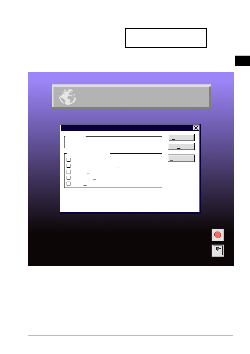
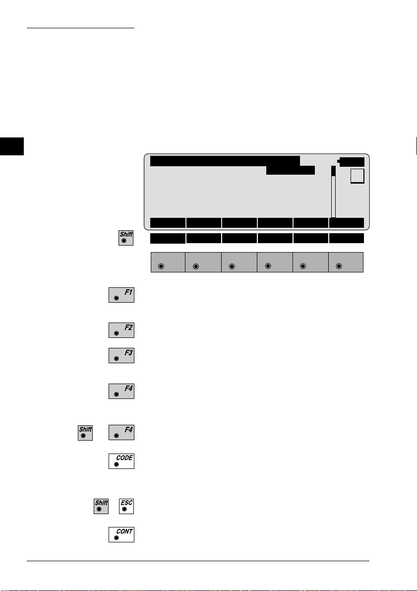
Loading files into the TPS1000 instruments
Applications, and system- and application texts, are
loaded into the TPS1000 by means of the "TPS
SOFTWARE UPLOAD" program.
Use the interface cable 563 625 to connect the
TPS1000 to the serial interface COM1 or COM2 on the
PC.
Start the "TPS SOFTWARE UPLOAD" program with a
double-click from the WINDOWS program manager.
Select the command "Sensor/Settings" and inspect the
interface selected and the baud rate. The baud rate
should be set to the maximum. The baud rate for the
TPS1000 instrument is set automatically .
TPS 1000 Settings
IN
COM-Port:
COM1
Baudrate
800
4
9600
19200
OK
Cancel
Help
© Leica TPS-System 1000 Programs-2.3.1en 17
Page 18
IN
View Applications & System
General Environment Applications
Name Art.No. Licence Code
Version Language
FreeSt_Ori_Res 663156 <none>
V 2.20 ENGLISH
—
TieDistance 663152 <none>
V 2.20 ENGLISH
Switch the instrument off! Select the command "View
Applications + System" to inspect the connection to the
instrument. The instrument switches itself on again and
establishes the connection. The display of the
applications available on the instrument shows that the
connection was successful. If it was not successful, read
section "Solving problems".
—
Stakeout 663155 <none>
V 2.20 ENGLISH
—
Close
18 TPS-System 1000 Programs-2.3.1en © Leica
Help
Page 19
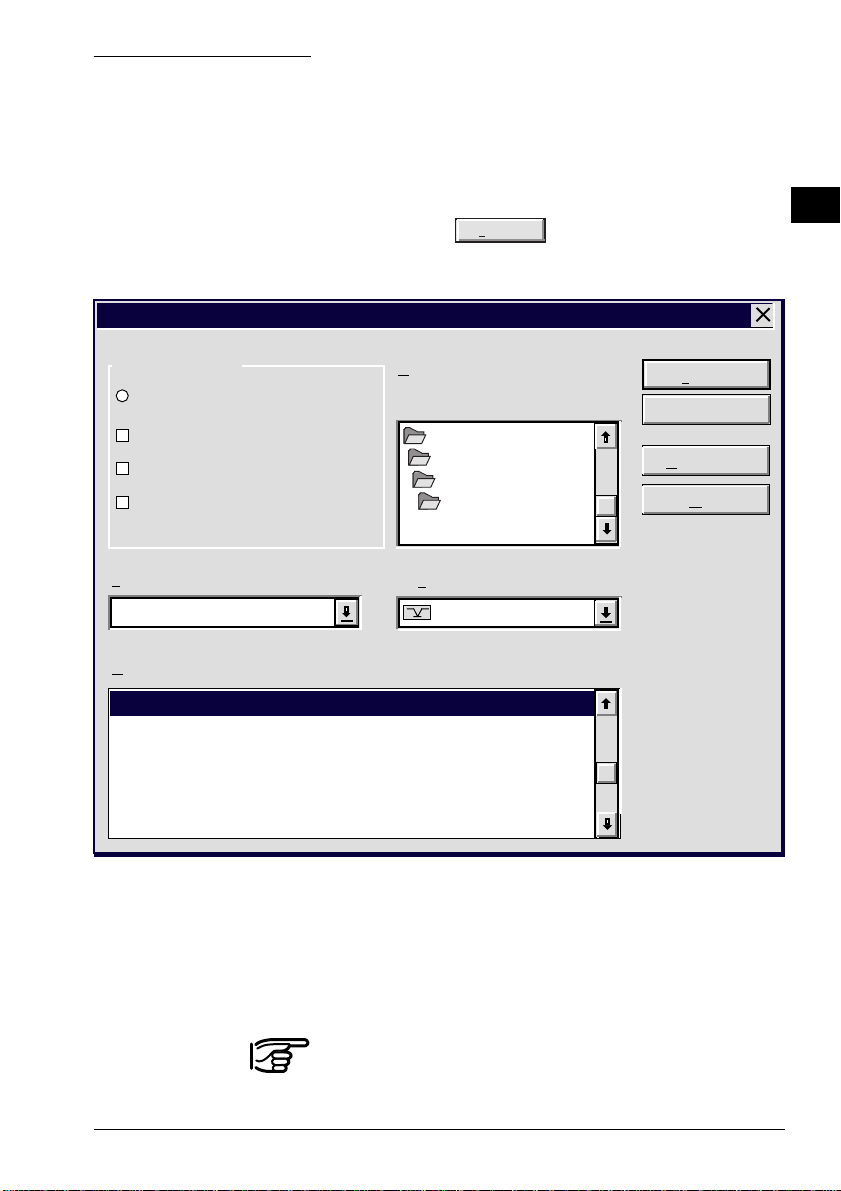
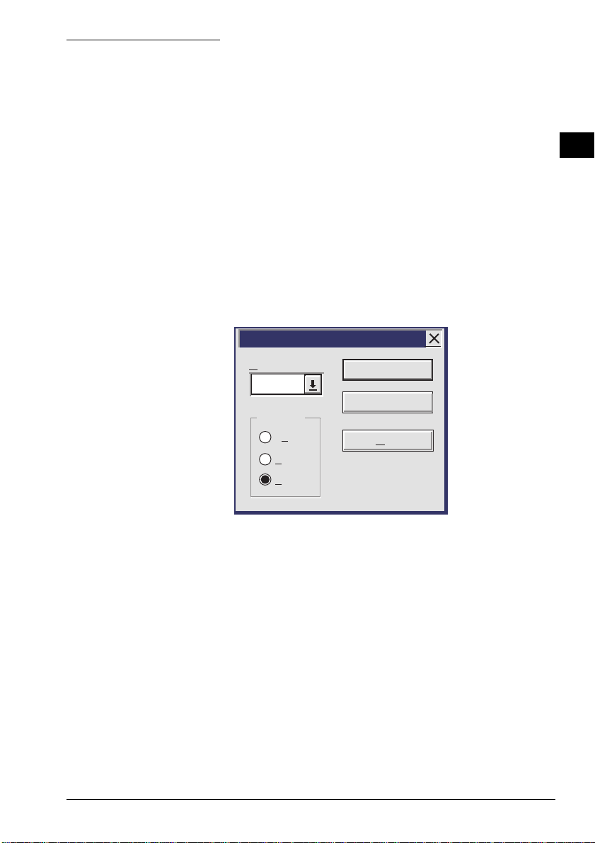
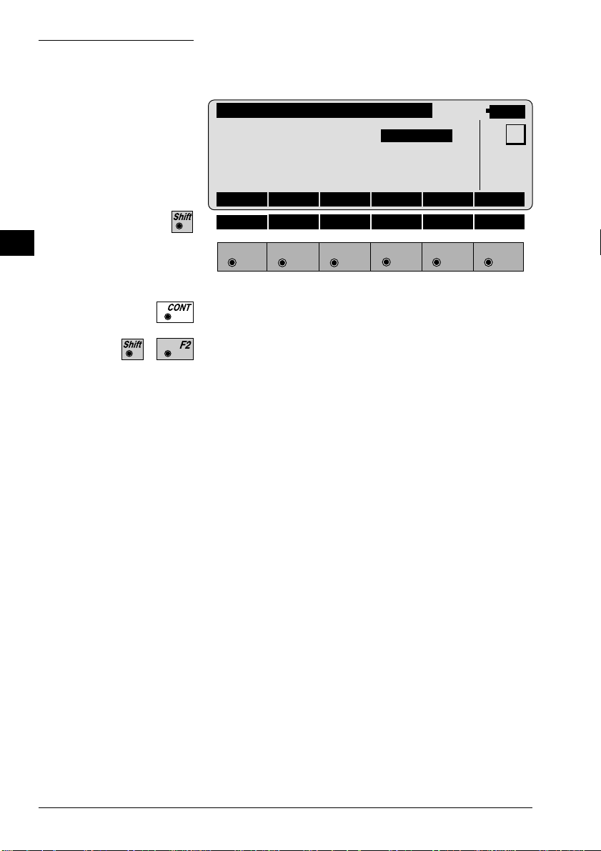
Loading system texts
Transfer
Transfer
- Select the command "Transfer files" in the "Utilities"
menu ,
- Mark "System Language",
- select relevant drive under "Directories",
- select desired language under "Language" and
- mark relevant file under "Components".
Then press the
key to start the transfer.
The progress of the transfer is shown in a bar diagram.
IN
Component T ype
System Software
System Language
ü
Application Program
EDM/ATR Firmware
Language:
ENGLISH-T
Components:
System Language (ENGLISH-T Version 2.20)
Directories:
i:\software\tps1000\V_2_20
Drives:
i:\
software
tps1000
V_2_20
i:
Transfer
Cancel
Settings ...
Help
Afterwards, enter the language on the instrument (see
section "Configuration" of "System" - user manual).
The English system texts are part of the system software
and can be neither loaded nor erased.
© Leica TPS-System 1000 Programs-2.3.1en 19
Page 20
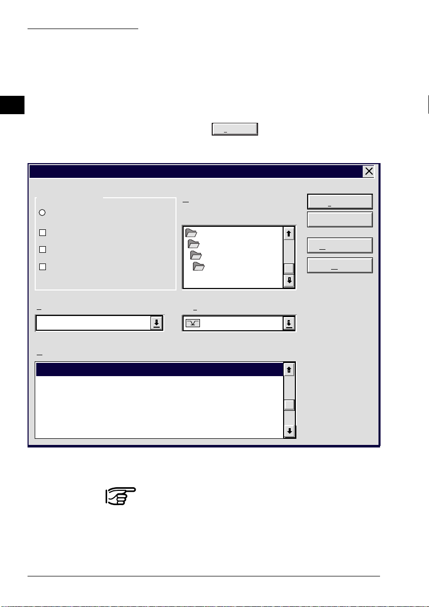
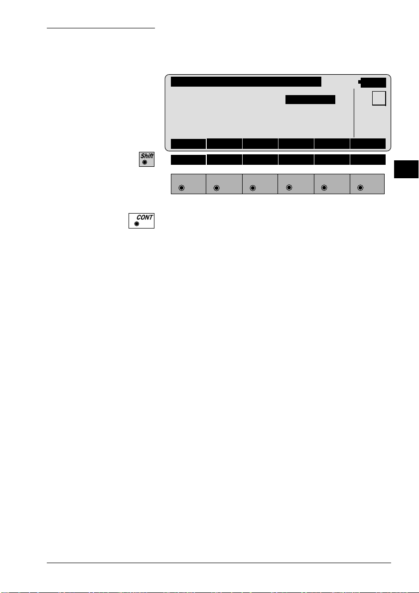
Loading application programs
IN
- Select the command "Transfer files" in the "Utilities"
menu ,
- Mark "Application Program",
- select relevant drive under "Directories",
- select desired language under "Language" and
- mark desired program(s) under "Components".
Then press the
The progress of the transfer is shown in a bar diagram.
Transf e r
Component T ype
System Software
System Language
ü
Application Program
EDM/ATR Firmware
Language:
ENGLISH-T
Components:
TPS-Application Area (V2.20)
TPS-Application COGO (V2.20)
TPS-Application FreeSt_Ori_Res (V2.20)
TPS-Application HiddenPoint (V2.20)
TPS-Application LocalRes (V2.20)
TPS-Application RefLine (V2.20)
Transfer
Directories:
i:\software\tps1000\V_2_20
i:\
software
tps1000
V_2_20
Drives:
i:
key to start the transfer.
Transfer
Cancel
Settings ...
Help
It is absolutely necessary that the program files
(*.prg) are be in the same directory as the language
files (*.LSS) and the Prtxt220.LSS file.
20 TPS-System 1000 Programs-2.3.1en © Leica
Page 21

Licence code
When an additional application is first started up, a
licence code is requested, so that the application will be
fully functional. Without this licence code, you can run
the applications as a demonstration version, but you will
not be able to calculate and store the results.
IN
The licence code is available from your Leica agency,
who will inform you about licence fees for additional
applications. Details of the licence agreement are given
in the registration card, which is a part of the "System"
manual.
To expedite formalities, please fill in a copy of the form
at the end of this section and fax it to your local Leica
agency.
Solving problems
1. Instrument does not switch on when "Utilities/View
Applications + System..." option is selected.
Inspect the cable connections and that the serial
interface COM1 or COM2 has been set correctly.
2. Instrument does not switch to "ON-LINE-MODE
(GeoCOM)" mode when "Utilities/View
Applications + System..." option is selected.
Make sure that the instrument is switched off before
the "Utilities/View Applications + System..." option
is activated.
3. Instrument does not switch to "ON-LINE-MODE
(GeoCOM)" mode when "Utilities/View
Applications + System..." option is selected;
"MEASURE & RECORD" menu or another autostart
application is displayed instead.
© Leica TPS-System 1000 Programs-2.3.1en 21
Page 22
Carry out the following operations on the instrument:
IN
or
until main menu is displayed.
[CONF] Configuration
[Autostart] Autoexec-application
[LIST] and select "MAIN MENU"
Switch off the instrument and start the data transfer
process from the beginning.
22 TPS-System 1000 Programs-2.3.1en © Leica
Page 23

Put crosses against the applications you require and send the form to your nearest
Leica agency, which will process your order.
Address of customer (please use Company stamp or write legibly)
Name
Company
Street
Zip code / City
Country
Telephone
Telefax
Remarks
(Company stamp, signature)
Leica Geosystems AG
Geodesy
CH-9435 Heerbrugg
(Switzerland)
Software Management Dept.
Phone +41 71 727 36 81
Fax +41 71 727 47 05
Licence code for TPS 1000 applications
Serial number TPS1000 Instrument type
Name of application No. of application Licence code Remarks
Free station survey 663156
Computation of area 663196
Traverse 663197
Reference line/building
alig.
Sets of angles 663199
663198
IN
Remote height 663200
Hidden points 663213
Local resection 663267
Road Line 663216
File Editor 663217
Road Plus 663218
COGO 664401
Monitoring 664411
To be filled
in by
agency and
forwarded
to Leica
Geosystems
AG,
Heerbrugg.
© Leica TPS-System 1000 Programs-2.3.1en 23
W e confirm taking out
a licence for the
applications listed
above, and we
guarantee to pay the
licence fees to Leica
Geosystems AG.
(Company stamp, signature)
Page 24

General notes
Units in this manual
Preparation
Specifications within this manual always apply to the
following units:
Units of length:
- in m (meters)
- in addition, within brackets in ft (feet)
Units of angle:
- in ° ' "
- in addition, within brackets in gon
Units of temperature:
- in °C
- in addition, within brackets in °F
All program sequences are based on a unified structure.
The clearly-designed display with the function keys
makes learning easy. Each program has a configuration
dialog. In this dialog, the user can match programspecific parameters to changes in requirements and
sequences. The various possibilities are described in the
instructions for the individual programs.
EL
GN
Settings
© Leica TPS-System 1000 Programs-2.3.1en 23
T o avoid temporarily-stored information being lost
when the TPS1000 automatically switches off after long
periods of disuse, you should set the "sleep mode"
instead of the automatic switchoff. For more
information, please refer to section "Fixed keys"
("Power off, Sleep") of "System" - user manual.
Each application takes over the settings (units,
recording format, display format etc.) allocated to the
appropriate user.
Page 25

If required, these user settings must be defined in
advance. For more information, please refer to section
"User configuration" of "System" - user manual.
EL
Data exchange If the settings in an application are altered, these
GN
changed values will be taken over in the other
applications also and in „Measure and record“. The
settings affected are the station coordinates and the
circle orientation, along with parameters such as the
reflector constant, reflector height, and data for distance
reduction. This data can be altered in every application.
The measurement data is stored in the file selected.
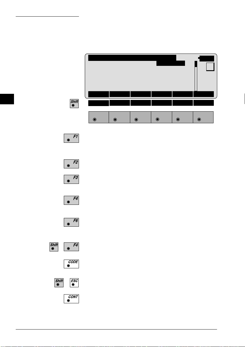
Using the program
Instrument field setup
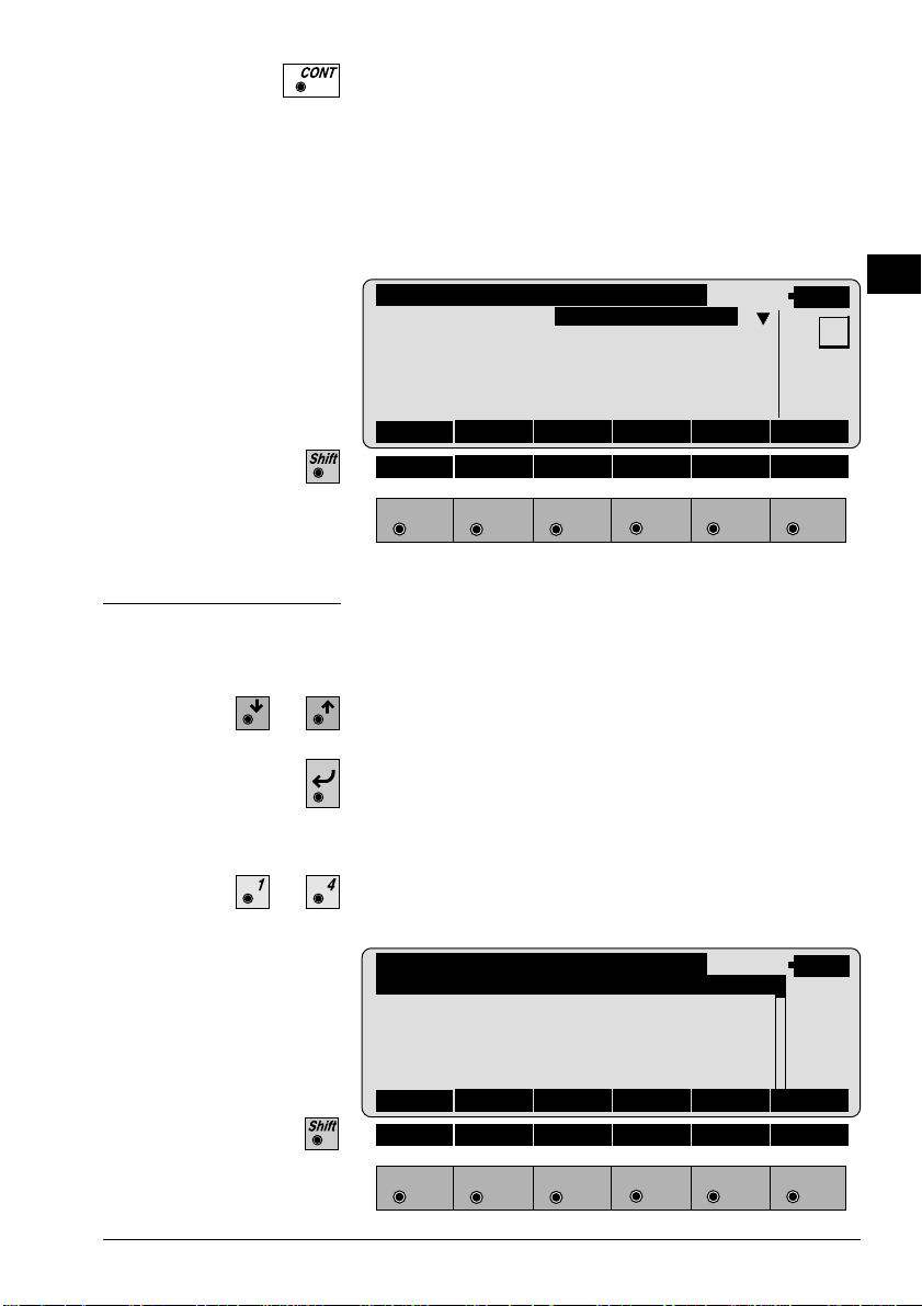
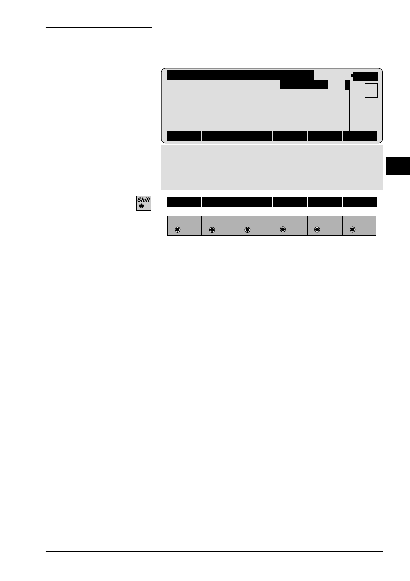
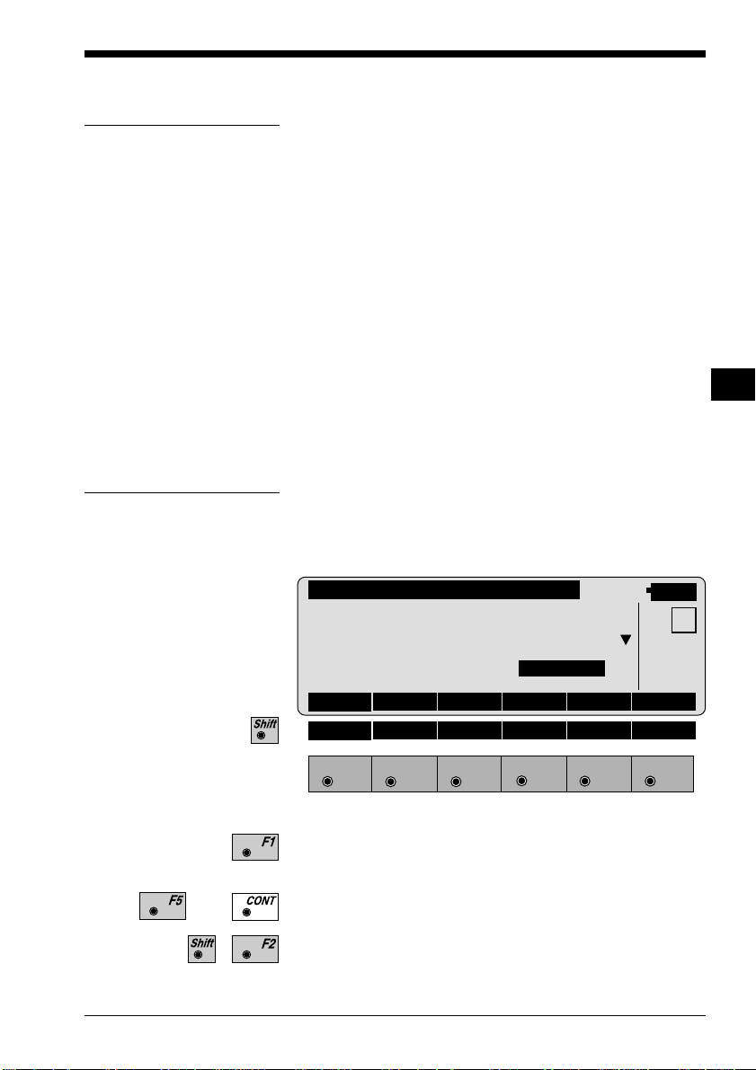
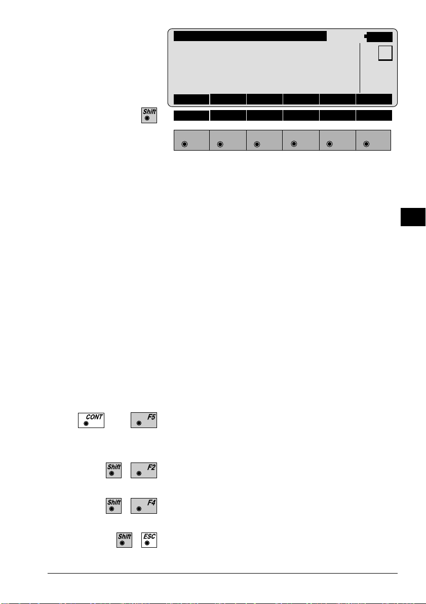
The setup is called up in the main menu.
To start with, the user profile and the file for storing
measurement data can be selected in the start-up
display .
SETUP\ START-UP DISPLAY
Select user template & files
User templ. :Polar(Standard)
Rec. device : Memory Card
Meas. file :1 √ FILE01.GSI
Data file :2 √ FILE02.GSI
14:03
QSET STN LIST
HELP
F1
24 TPS-System 1000 Programs-2.3.1en © Leica
F2 F3
F4
F5 F6
Page 26
The station number, the coordinates, the direction of the
line of sight, and the instrument height, are all displayed
The dialog enables station coordinates to be set or
imported and also permits a direction to a tie point to be
set.
SETUP\ STATION DATA
14:03
Station no. : STATION 12
Inst.Height : 1.634 m
Stat.Easting: 1010.567 m
MC
Stat.Northg : -34213.077 m
Stat.Elev. : 345.655 m
Hz : 390°35'58"
REC Hz0 IMPOR αNUM
HELP
EL
GN
Calling up the program
...
F1
F2 F3
F4
F5 F6
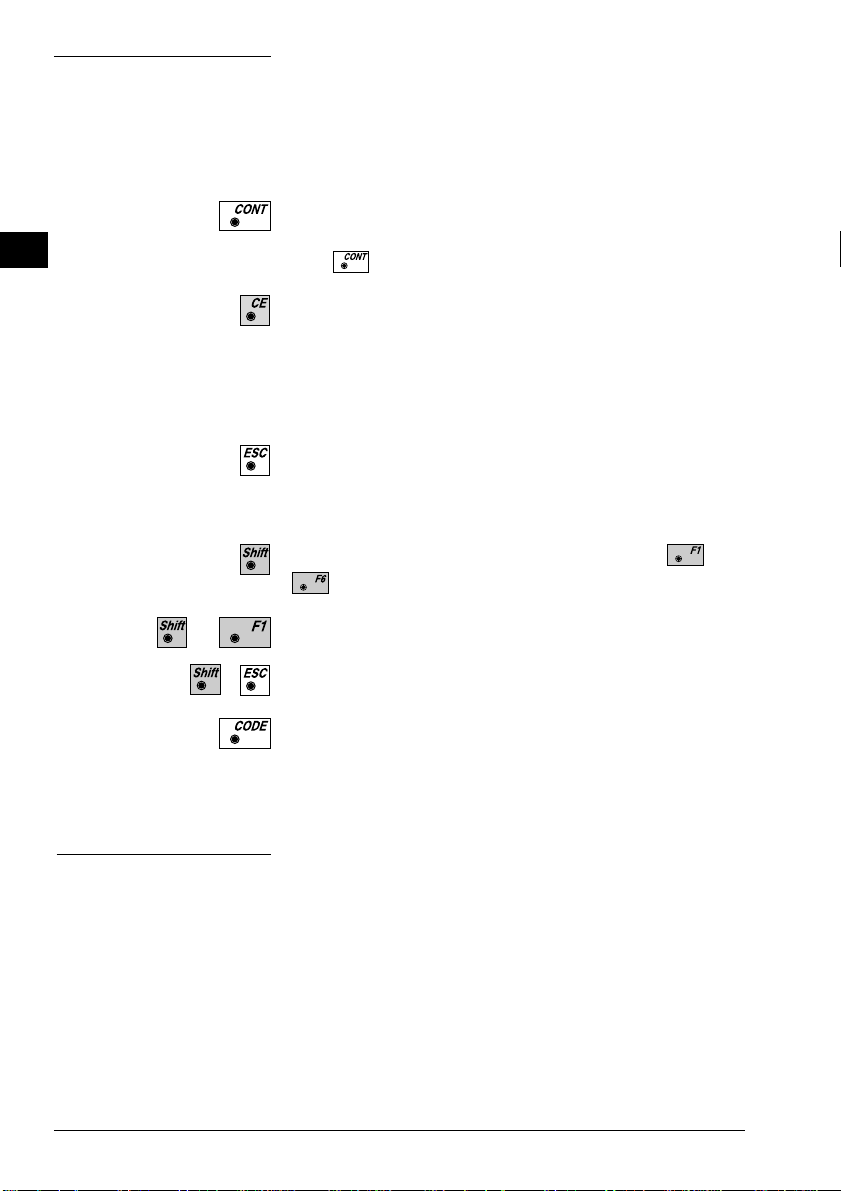
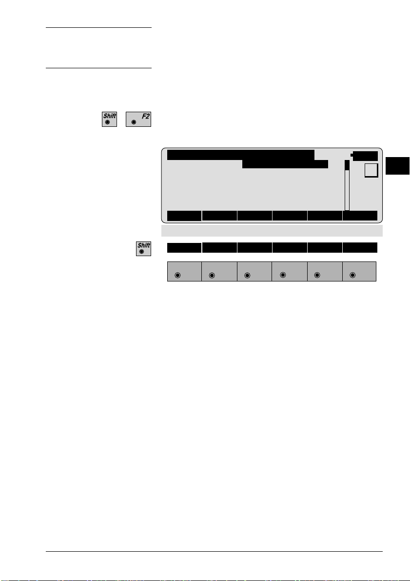
The applications are called up in the main menu.
Select the application required and
confirm
or
alternatively type in the number which appears after the
program name in the display.
MAIN MENU: PROGRAMS
14:03
Orientation & Ht. Transfer 00
Resection 01
Stakeout 02
Tie Distance 03
Free Station 04
EXTRA CAL CONF DATA SETUP MEAS
HELP
F1
© Leica TPS-System 1000 Programs-2.3.1en 25
F2 F3
F4
F5 F6
Page 27
Designation of keys
EL
GN
The effects of the fixed keys and of a few function keys are
the same as their effects in "MEASURE AND RECORD".
These keys are generally omitted from the descriptions
of the applications and from the ON-LINE help.
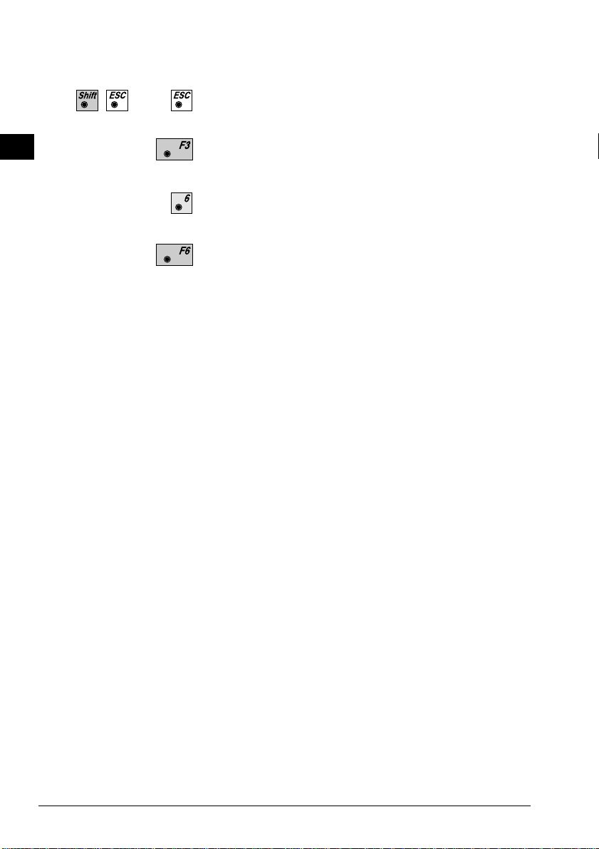
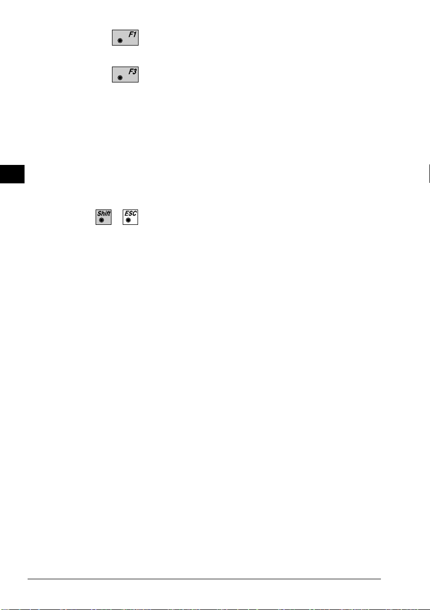
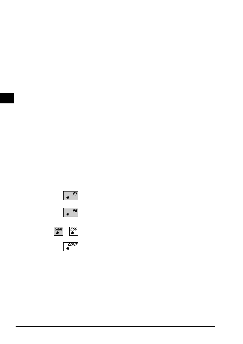
Continues sequence after input, measurements etc. have
been concluded. If the measurement dialog is concluded
with the measurement data will not be recorded.
Erases incorrect alphanumeric input.
T arget eccentricity
"REC"
Records in a pre-established format manually-entered
coordinates, measurements or the results of
calculations.
Quits current dialog and calls up previous dialog.
Changes and inputs to dialog are rejected and are not
stored.
Displays the second level of the function keys -
.
Calls ON-LINE help.
Closes application.
Calls up code input or code function in measurement
dialog.
If the reflector cannot be set up directly over the
desired point, or if the point cannot be seen from the
instrument, the function 'OFFS' may be used to make an
offset measurement.
Previous to the input of the values for eccentricity, a
distance must be measured to the reflector.
For more information, please refer to section
'Measurement & recording' of 'System'-user manual.
26 TPS-System 1000 Programs-2.3.1en © Leica
Page 28
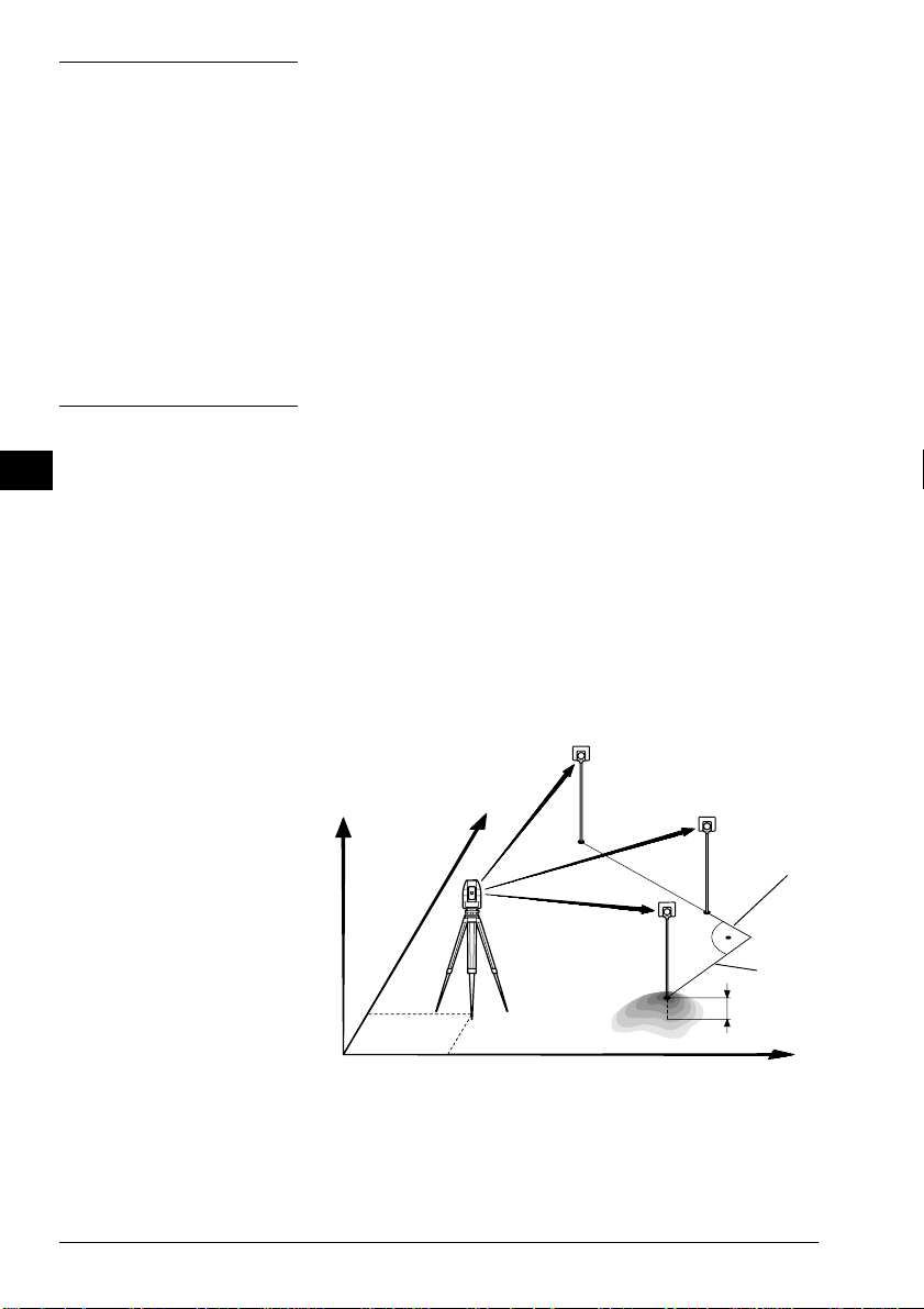
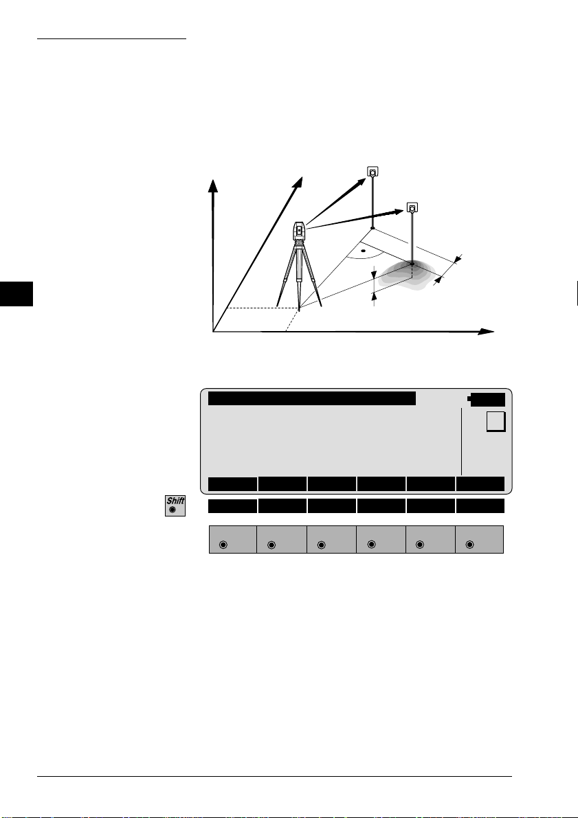
Orientation and Height Transfer
Introduction
This manual describes the "Orientation and Height
Transfer" program of the TPS SYSTEM 1000
theodolite series.
0°00'00"
HN
E0
PROG_Z01
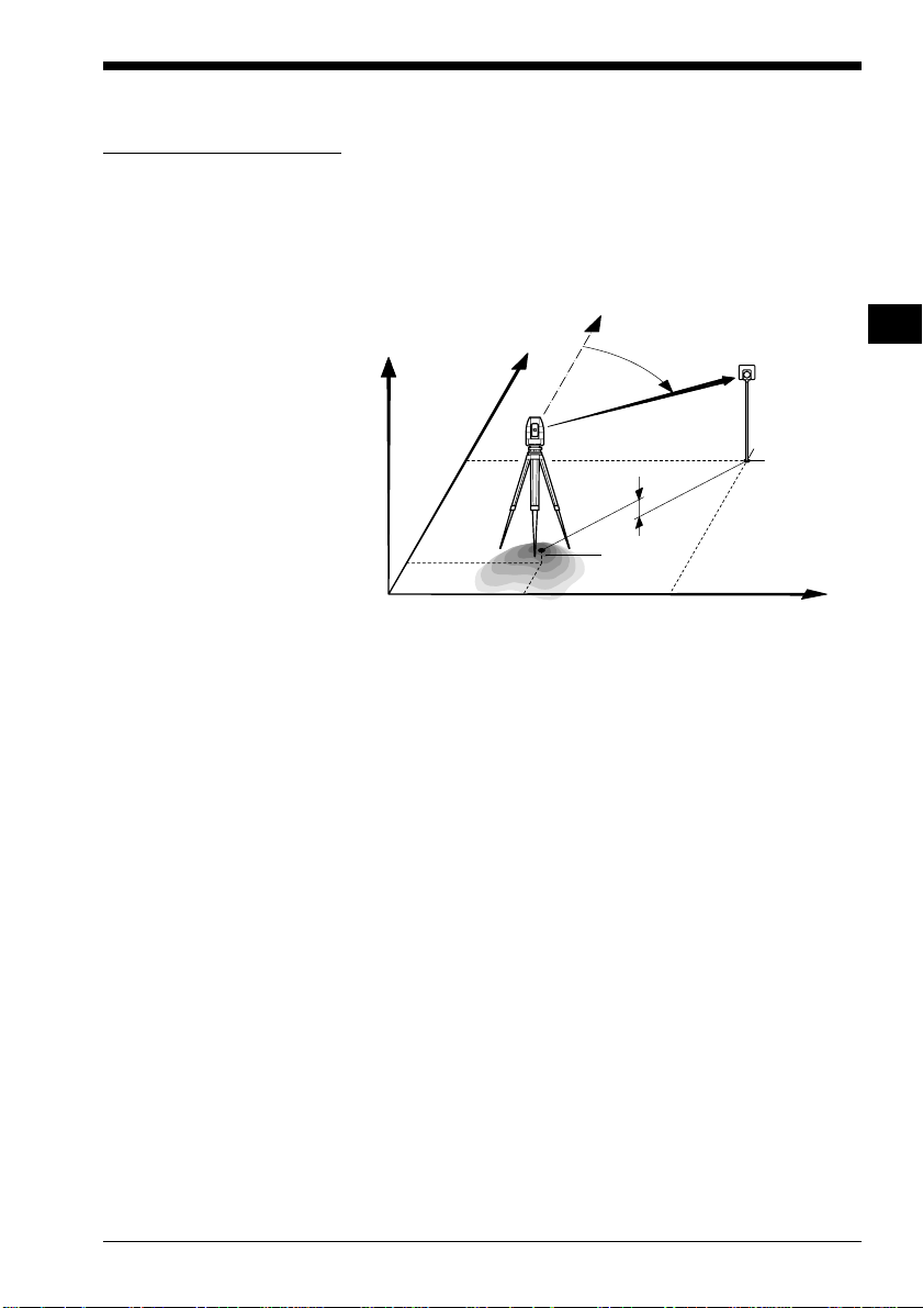
The instrument must be set up on a known point. The
program "ORIENT ATION" calculates an angular
correction for the instruments horizontal circle, so that
0.0000 of the horizontal circle corresponds with grid
north (Orientation correction), using reference points
with known Easting and Northing.
N0
H0
Hz
E
∆H
H
N
OH
E
For simultaneous determination of the station elevation,
height of instrument and height of reflector must
already have been input and the elevation of the target
points must be known.
The program handles a maximum of 10 points.
© Leica TPS-System 1000 Programs-2.3.1en 27
Page 29
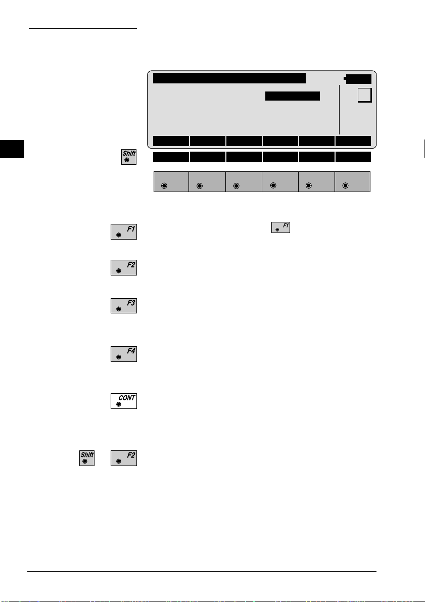
Target Point
Enter the target point number and height of the reflector
.
OH
ORINT\ TARGET POINT
Point no. : 12
Refl.Height : 1.300 m
14:03
MC
CALC LIST <-- -->
HELP CONF
F1
F2 F3
F4
F5 F6
Run the calculation. Note, the key will be assigned
after the first measurement.
Entry of target points into a list as well as selecting
points for further use.
Displays the previous point from the list of points
entered. Note that this key will not be available until
there is at least one point in the list.
Displays the next point in the list of points entered.
Note that this key will not be available until there is at
least one point in the list.
Retrieve the coordinates of the target point from the
selected file. For further information, please refer to
dialog "IMPORT" described in the "System" - user
manual.
Start the "CONFIGURATION"
28 TPS-System 1000 Programs-2.3.1en © Leica
Page 30

Point List
Enter a maximum of 10 points. The same point can be
retrieved several times.
ORINT\ POINT LIST
Point 1 : 1
Point 2 : 2
Point 3 : 3
Point 4 : 4
Point 5 : 5
Point 6 : 6
Point 7 : 7
Point 8 : 8
Point 9 : 9
Point10 : 0
HELP
F1
F2 F3
F4
Return to the dialog "T ar get Point".
14:03
MC
OH
F5 F6
© Leica TPS-System 1000 Programs-2.3.1en 29
Page 31
Measure Mode
OH
This dialog is similar to the TPS 1000’s basic "Measure
Mode" dialog. Once a measurement is taken, the
program will return to the dialog "Target Point" to
acquire the next point for measuring.
If the orientation correction can be calculated
successfully from any of the first measurements, the
∆Hz and ∆V values are displayed for further entered
target point. Motorized theodolites will automatically
drive the telescope to the target point.
ORINT\ MEASURE MODE (GSI)
Point no. : 1
Hz : 216°55'50"
V : 71°16'20"
Refl.Height : 1.300 m
Slope Dist. : 385.231 m
∆Hz : -----
14:03
ALL DIST REC TARGT
HELP I<>II
MC
F1
F2 F3
F4
F5 F6
Simultaneously measure and record data on the active
recording device. Return to the dialog "Target Point".
Measure a distance.
Record the measurement on the active recording device.
Return to the dialog "Target Point".
Enter target data. For further information, please refer
to chapter "Measure & Record" described in the
"System" - user manual.
Change the theodolite face.
Call up the CODE function, as described in chapter
"Measure & Record" described in the "System" - user
manual.
Exit the program.
Accept the measurement and return to the dialog
"Target Point".
30 TPS-System 1000 Programs-2.3.1en © Leica
Page 32

Calculation
Calculates the orientation, the elevation and the
respective standard deviations.
ORINT\ RESULTS <ROBUST>
Station no. : 10
No. of Pts. : 5
Inst.Height : 1.635 m
Easting : 2134.234 m
Northing : 4723.365 m
Elevation : 521.643 m
14:03
S.ORI S.HT STORE PLOT MORE
Orientation : 2°12'34"
σElevation : 0.010 m
σOrient : 0°00'03"
HELP LSQRS
F1
F2 F3
F4
F5 F6
Station no : Point number assigned to the station
No. of Pts : Number of points measured
Inst.Height : Instrument Height
Easting : Easting of the station entered.
Northing : Northing of the station entered.
Elevation : Calculated elevation of the station
MC
OH
Orientation : Oriented direction
σσ
σ Elevation : Standard deviation of the Elevation
σσ
σσ
σ Orient : Standard deviation of the Orientation
σσ
Set orientation on the instrument. Note that once this
key has been pressed it will not be possible to
execute more measurements.
Set station elevation on the instrument. Note that once
this key has been pressed it will not be possible to
execute more measurements.
© Leica TPS-System 1000 Programs-2.3.1en 31
Page 33

Record the following results into the active file:
WI 11 Station Point Number
WI 25 Orientation correction
WI 84 Station Easting
WI 85 Station Northing
WI 86 Station Elevation
WI 87 Last reflector height used
WI 88 Instrument Height
OH
More Information
Sketch of the station and the reference points used.
Show the results of individual measurements on the
screen (see dialog "More Information").
Measure more points. The program will recall the
"TARGET POINT" dialog.
Select between the "Robust" method and the "Variation" method.
Display the residuals of individual measurements. You
can also disable points from the calculation of
orientation or height as well as delete erroneous
measured points.
ORINT\ MORE INFORMATION
Use for HT. : YES Status: ON
Point no. : Point01
Error flag : NONE
∆ Hz : 0°00'03"
∆ Distance : 0.050 m
14:03
2/10
RECLC <-- --> MEAS DEL NO
∆ Height : 0.020 m
Refl.Height : 1.555 m
Easting : 991.427 m
Northing : 1995.162 m
Elevation : 402.466 m
MC
HELP
F1
32 TPS-System 1000 Programs-2.3.1en © Leica
F2 F3
F4
F5 F6
Page 34

2/10 : Sequence number of the current point
and total number of points in the
measurement set. The scroll bar shows
the sequential position of the
measurements, graphically.
Use for Ht. : Use this measurement for height
determination (YES/NO)
Status : Use this measurement for calculation
(ON/OFF).
Point no : The target point number.
Error Flag : Identified erroneous measurements.
Possible values are:
NONE measurement is OK
HZ horizontal angle error
DIST distance error
HT height difference error
The flags may also be combined, i.e.
DIST + HZ
∆∆
∆ Hz. : Difference between calculated and
∆∆
measured horizontal angle
∆∆
∆ Distance : Difference between calculated and
∆∆
measured distance
∆∆
∆ Height : Difference between calculated and
∆∆
measured height
Refl. Ht. : Reflector height used for the target
point
Easting, Northing, Elevation: Ta rget coordinates used.
OH
Recalculate the result.
Scroll to the measurements of the previous point.
Scroll to the measurements of the following point.
Measure more points. Return to the dialog "Target
Point".
Delete a point from the set of measurements. You can
now measure a new point in its place.
Exit the program.
© Leica TPS-System 1000 Programs-2.3.1en 33
Page 35

OH
Plot
Generates a plot showing the measurement
configuration.
The station point is in the center and the top of the
sketch shows the direction of grid north. The sketch is
true in angular but not true in distances.
Points are numbered sequentially in the order in witch
they were measured.
Points not used in the calculation are marked with a
dotted line.
ORINT\ PLOT
2
3
4
1
5
14:03
MC
RECLC MEAS
HELP
F1
F2 F3
F4
F5 F6
Recalculate the result and return to the dialog
"CALCULATION RESULTS".
Measure more points. The program will recall the
"TARGET POINT" dialog.
...
T oggle any point ON or OFF by pressing the numeric
key corresponding to the sequence number of the point.
Note, that represents point 10
Exit the program.
34 TPS-System 1000 Programs-2.3.1en © Leica
Page 36

Configuration
Configuration Editor
Start the "Configuration Editor" from the "TARGETPOINT" dialog.
OH
ORINT\ CONFIGURATION
Hz Ori Acc : 0°00'32"
Ht Acc TP : 0.0250 m
Posn Acc TP : 0.0250 m
Two faces : NO
User Displ : NO
Log File : OFF
14:03
INFO DFLT EDIT
Log FlName : ORIENT.LOG
HELP
F1
F2 F3
F4
F5 F6
The "Configuration Editor "sets parameters for further
program operations:
Hz Ori Acc : Limit for the standard deviation of the
orientation. The orientation is
regarded as "error free", if the
computed standard deviation of the
orientation is within twice the entered
value.
MC
Ht Acc TP : Height accuracy of the target points.
The entered value, is used as an "a
priori" accuracy in the calculation.
The height is regarded as "error free",
if the computed standard deviation is
within twice the entered value.
© Leica TPS-System 1000 Programs-2.3.1en 35
Page 37

OH
Posn Acc TP : Position accuracy of the target points.
The entered value, is used as an "a
priori" accuracy in the calculation.
The position is regarded as "error
free", if the computed standard
deviation is within twice the entered
value.
Two Faces : YES for dual-face measurement,
NO for single-face.
User Disp : YES; the measured value indication is
used from application "Measure and
record".
NO; the default indication is used for
"Orientation and Height Transfer".
Log File : ON, records measurements in a Log-
File.The format is described on page
37.
Log FlName : Enter the Log File Name.
Displays date and version.
Set the values to default. Default values are shown in
dialog on page 35.
Exit the program.
Store the current configuration and proceed to the
dialog "TARGET POINT".
36 TPS-System 1000 Programs-2.3.1en © Leica
Page 38

Dual-face Measurement
In the dual-face mode, the program will prompt for
measurements in both faces. When both measurements
are taken, the program will check the difference
between the two. If the difference in angle is within 27'
(0.5 gon) and the difference of two measured distances
is within 0.5 m (1.64 ft), the observations will be
averaged. These tolerances are used to avoid errors in
target identification. If exceeded an error message will
be displayed.
OH
Log file
If "Log File" is set to "ON" the measurements and the
results are stored in the ASCII-file specified within the
"Configuration Editor". This file is created in the
directory LOG on the memory card. Subsequently, you
can read the memory card on your PC and obtain a hard
copy of the Log-file.
Data will always be appended to the specified Logfile.
The Log-file contains the following information:
Header The header line will contain the
program used, information about the
instrument, the name of the data file as
well as date and time.
© Leica TPS-System 1000 Programs-2.3.1en 37
Page 39

Record For each measurement, a record will be
stored containing :
• Station coordinates
• station height,
• orientation correction
• standard deviations for
height and
orientation correction
OH
The residuals for:
• horizontal angles,
• heights and
• measured distances
are also listed.
Leica VIP Orientation + Ht. Transfer V 2.10
Instrument : TCM1100, Serial 412160, (not named)
User templ. : User 1
Meas. file : FILE12.GSI
Program Start : 09/04/1996 at 12:57
Station no. : 2000
E= -0.0006m N= -0.0002m ELV= 398.3961m hi= 1.6000m
Using Robust Solution
Station Elev. : 398.3929m
Ori.Corr. : 40'36"
S.Dev. Elev. : 0.0035m
S.Dev. Orient. : 0°00'04"
3 point(s) measured :
## Point no. ∆ Hz ∆ Height ∆ Distance Error Flag
1 500 -0°00'55" 0.0026m 0.0020m NONE
2 501 -0°00'48" 0.0044m 0.0016m NONE
3 502 0°00'52" -0.0070m -0.0000m NONE
Typical log file entry in the "Orientation and Height Transfer" program
38 TPS-System 1000 Programs-2.3.1en © Leica
Page 40

Resection
Introduction
This manual describes the "Resection" program of the
TPS SYSTEM 1000 theodolite series.
Pt2
H
N
D2
0°00'00"
Hz1
Pt1
D1
Hz2
E0
PROG_Z02
N0
H0
E
The program can be used to deduce the three-dimensional coordinates for the instrument station and the
orientation of the horizontal circle from measurements
to 2 target points with know Easting and Northing. To
compute the position coordinates, at least the distances
and the directions for both points are necessary.
For simultaneous determination of the station elevation,
height of instrument and height of reflector must
already have been input and the elevation of the target
points must be known.
IV
EL
AH
OH
RE
The program allows measurement in single or dual-face
mode.
© Leica TPS-System 1000 Programs-2.3.1en 39
Page 41
Station Data
Enter station point number and height of the instrument.
IV
EL
AH
OH
RE
RESEC\ STATION DATA
14:03
Station no. : 1
Inst.Height : 1.555 m
HELP CONF
F1
F2 F3
F4
Proceed to the dialog "Target PoinT"
Start the "Configuration"
MC
αNUM
F5 F6
40 TPS-System 1000 Programs-2.3.1en © Leica
Page 42
Target Point
Enter the target point number and height of the
reflector.
RESEC\ TARGET POINT
14:03
Point no. : 30
Refl.Height: 1.300 m
IMPOR αNUM
HELP
F1
F2 F3
F4
F5 F6
Retrieve the coordinates of the point entered from the
active file. For further information, please refer to
dialog "Import" described in the "System" - user
manual.
MC
IV
EL
AH
OH
RE
© Leica TPS-System 1000 Programs-2.3.1en 41
Page 43
Measure Mode
IV
This dialog is similar to the TPS System1000’s basic
"Measure Mode" dialog. Once a measurement is taken,
the program will return to the dialog "T arget Point" to
acquire the next point for measuring.
EL
AH
OH
RE
RESEC\ MEASURE MOD (GSI)
Point no. : 1
Hz : 286°55'50"
V : 91°16'20"
Refl.Height : 0.000 m
Slope Dist. : ----- m
14:03
MC
I
ALL DIST REC TARGT αNUM
HELP I<>II
F1
F2 F3
F4
F5 F6
Simultaneously measure and record data on the active
recording device. Return to the dialog "TARGET
POINT".
Measure a distance.
Record the measurement on the active recording device.
Return to the dialog "TARGET POINT".
Enter target data as described in chapter "Measure &
Record" of the "System" - user manual.
Assigned with "aNUM" at point number input; assigned
with "EDIT" at numerical input.
Change the theodolite face.
Call up the CODE function, as described in chapter
"Measure & Record" of the "System" - user manual.
Exit the program.
Accept the measurement and return to the dialog
"TARGET POINT".
42 TPS-System 1000 Programs-2.3.1en © Leica
Page 44
Calculation
In this dialog the calculated station coordinates are
shown with the orientation.
RESEC\CALCULATION RESULTS
Station no. : 1
No. of Pts. : 2
Inst.Height : 1.635 m
Easting : 2134.234 m
Northing : 4231.365 m
Elevation : 580.643 m
14:03
MC
SET STORE
Orientation : 2°12'34"
σEasting : 0.003 m
σNorthing : 0.005 m
σElevation : 0.005 m
σOrient : 0°00'03"
HELP
F1
F2 F3
F4
F5 F6
Station no : Station point number
No. of Pts : Number of points measured
Inst.Height : Instrument Height
Easting : Calculated Easting (Y) for the station.
Northing : Calculated Northing (X) for the station.
IV
EL
AH
OH
RE
Elevation : Calculated elevation for the station
Orientation : Oriented direction
σσ
σ Easting : Standard deviation of Easting
σσ
σσ
σ Northing : Standard deviation of Northing
σσ
σσ
σ Elevation : Standard deviation of the Elevation
σσ
σσ
σ Orient : Standard deviation of the Orientation
σσ
© Leica TPS-System 1000 Programs-2.3.1en 43
Page 45
IV
Set orientation and station coordinates on the
instrument. Note that this key will end the program.
Record the following results on the active recording
device:
EL
AH
OH
RE
WI 11 Station Point Number
WI 25 Orientation correction
WI 84 Station Easting
WI 85 Station Northing
WI 86 Station Elevation
WI 87 Last rflector height used
WI 88 Instrument Height
Exit the program.
44 TPS-System 1000 Programs-2.3.1en © Leica
Page 46
Configuration
Configuration Editor
Start the "Configuration Editor" from the "STATION
DA TA" dialog.
RESEC\ CONFIGURATION
Hz Ori Acc : 0°00'32"
Ht Acc TP : 0.025 m
Posn Acc TP : 0.025 m
Two Faces : NO
User Displ : NO
Log File : OFF
14:03
INFO DFLT EDIT
Log FlName : RESECT.LOG
HELP
F1
F2 F3
F4
F5 F6
The "Configuration Editor" sets parameters for further
program operations:
Hz Ori Acc : Limit for the standard deviation of the
orientation. The orientation is
regarded as "error free", if the
computed standard deviation of the
orientation is within twice the entered
value.
IV
EL
AH
OH
RE
MC
Ht Acc TP : Height accuracy of the target points.
The entered value, is used as an "a
priori" accuracy in the calculation.
The height is regarded as "error free",
if the computed standard deviation is
within twice the entered value.
© Leica TPS-System 1000 Programs-2.3.1en 45
Page 47
IV
EL
Posn Acc TP : Position accuracy of the tar get points.
The entered value, is used as an "a
priori" accuracy in the calculation.
The position is regarded as "error
free", if the computed standard
deviation is within twice the entered
value.
AH
OH
RE
Two Faces : YES for dual-face measurement,
NO for single-face.
Ben.Anzeige : YES; the measured value indication is
used from application "Measure and
record".
NO; the default indication is used for
the "Resection".
Log File : Set to ON, the program will record
measurement data in a log file as
described on page 47.
Log FlName : Enter the Log File Name.
Displays date and version.
Set the value to the default as described in dialog on
page 45.
Exit the program.
Store the current configuration and proceed to the
dialog "STATION DATA".
46 TPS-System 1000 Programs-2.3.1en © Leica
Page 48

Dual-face Measurement
In the dual-face mode, the program will prompt for
measurements in both faces. When both measurements
are taken, the program will check the difference
between the two. If the difference in angle is within 27'
(0.5 gon) and the difference of two measured distances
is within 0.5 m (1.64 ft), the observations will be
averaged.
These tolerances are used to avoid errors in target
identification.
If exceeded an error message will be displayed.
IV
EL
AH
OH
RE
Log File
If "Log File" is set to "ON" the measurements and the
results are stored in the ASCII-file specified within the
"Configuration Editor". This file is created in the
directory LOG on the memory card. Subsequently, you
can read the memory card on your PC and obtain a hard
copy of the Log-file.
Data will always be appended to the specified Log-file.
The Log-file contains the following information:
Header The header line will contain the
program used, information about the
instrument, the name of the data file as
well as date and time.
Record For each measurement, a record will
be stored containing :
Station coordinates and orientation
correction, standard deviation for
Easting, Northing, Height of station
and orientation correction.
The residuals for horizontal angles,
heights and measured distances are
also listed.
© Leica TPS-System 1000 Programs-2.3.1en 47
Page 49

IV
EL
AH
OH
Leica VIP Resection V 2.10
Instrument : TCM1100, Serial 412160, (not named)
User templ. : User 1
Meas. file : FILE12.GSI
Program Start : 09/04/1996 at 12:52
Using Least-Squares Solution
Station no. : 2000
E= -0.0011m N= -0.0006m ELV= 398.3951m hi= 1.6000m
RE
Ori.Corr. ; 240°50'51"
S.Dev. East : 0.0003m
S.Dev. North : 0.0003m
S.Dev. Elev. : 0.0047m
S.Dev. Orient. : 0°00'49"
2 point(s) measured :
## Point no. ∆ Hz ∆ Height ∆ Distance Error Flag
1 500 -0°00'55" 0.0047m 0.0001m NONE
2 501 -0°00'18" -0.0047m 0.0002m NONE
Typical log file entry in the "Resection" program
48 TPS-System 1000 Programs-2.3.1en © Leica
Page 50

Tie Distance
Introduction
This manual describes the "Tie Distance" program of
the TPS SYSTEM 1000 theodolite series.
The program calculates the length and azimuth of a line
connecting two points.
Polygonal or Radial methods can be used as shown in
the illustrations.
The data for the points can either be measured or
retrieved from the selected file. Measured points and
points retrieved from the selected file can be used
together in the calculations, if the station coordinates
and orientation are set correctly.
In Polygonal Mode, the program will calculate the
distance between the last two points measured (eg. Pt3 Pt4).
0°00'00"
H
N
Pt1
Hz1
Pt2
Pt3
Hz2
Hz3
Pt4
IV
EL
AH
OH
BS
TD
Slope Dist 1
Slope Dist 2
E0
PROG_Z03
© Leica TPS-System 1000 Programs-2.3.1en 49
N0
Slope Dist 3
E
Polygonal Mode
Page 51

IV
EL
AH
OH
BS
TD
In Radial Mode, the program will calculate the distance
between the last point measured (called a Radial Point)
(Pt2, Pt3 ...) and a fixed Center Point (Pt1).
0°00'00"
Pt2
Pt3
Pt4
Slope Dist 2
Slope Dist 3
H
PROG_Z04
E0
Pt1
N
0°00'00"
Hz3
Hz2
Hz1
Slope Dist 1
N0
Radial Mode
E
T oggling between Polygonal and Radial Mode at any
time while working is possible.
50 TPS-System 1000 Programs-2.3.1en © Leica
Page 52

Measure Mode
This dialog is used in accordance with the settings of
the system function "Measure & Record" or according
to the dialog shown below.
IV
TIED\ FIRST POINT
Point no. : 546
Refl.Height : 1.654 m
Hz : 230°45'23"
V : 4°52'35"
Slope Dist. : ----- m
Height diff : ----- m
14:03
ALL DIST REC TARGT IMPOR
Easting : ----- m
Northing : ----- m
Elevation : ----- m
HELP CONF I<>II
F1
F2 F3
F4
F5 F6
The input for the start point is only possible after the
program start or with the function in the dialog
"RADIAL MODE".
For all following points the program requests (NEXT
POINT).
The dialog for the following points is identical with
dialog above, except for the title.
Simultaneously measure and record in the active file.
Proceed with the dialog "NEXT POINT". If the second
point has already been measured, the program will
proceed to the "RESULT" dialog.
MC
EL
AH
OH
BS
TD
Measure a distance. Record the measurement in the
active file and proceed with the dialog "NEXT
POINT". If the second point has already been
measured, the program will proceed to the "RESULT"
dialog.
Measure the distance. Accept the measurement without
recording. If the second point has already been
measured, the program will proceed with the
"RESULT" dialog.
© Leica TPS-System 1000 Programs-2.3.1en 51
Page 53

Enter the target data.
For further information refer to chapter "Measure &
Record" of "System" - user manual.
IV
EL
AH
OH
BS
TD
Import target coordinates.
For further information, please refer to chapter "Setup"
of "System" - user manual.
Start the "Configuration Editor".
Change the theodolite face.
Call up the CODE function, as described in chapter
"Measure & Record" of "System" - user manual.
Exit the program
52 TPS-System 1000 Programs-2.3.1en © Leica
Page 54

Results
This dialog shows the results computed from the last
two points, which can be measured or retrieved from
the active file. The same results are calculated for both
methods.
IV
Using "Polygon Mode" the calculations are always
based on the last two points, where as the "Radial
Mode" always uses the first point as a reference point.
TIED\ RADIAL MODE
Center Pt. : 12
Radial Pt. : 13
Hori.Dist. : 4.567 m
Azimuth : 342°52'35"
∆ Height : 2.543 m
Slope Dist. : 4.946 m
14:03
N.PKT N.ZEN STORE POLYG
∆Easting : 22.432 m
∆Northing : 50.083 m
HELP
F1
F2 F3
F4
F5 F6
Center Pt. : Point number of the center point
Radial Pt. : Point number of the radial point
EL
AH
OH
BS
MC
TD
Hori.Dist : Horizontal distance between the two
points
Azimuth : Azimuth from point 1 to point 2
∆∆
∆ Height : Height difference between point 1 and
∆∆
point 2 (H2 - H1).
Slope Dist : Slope distance between the two points
© Leica TPS-System 1000 Programs-2.3.1en 53
Page 55
IV
EL
AH
OH
BS
TD
∆∆
∆ Easting : Difference in Easting between point 1
∆∆
and point 2 (E2 - E1).
The grid coordinates are only valid for
oriented instruments set up on a
known point.
∆∆
∆ Northing : Difference Northing between point 1
∆∆
and point 2 (N2 - N1).
Note, the grid coordinates are only
relevant for oriented instruments set
up on a known point.
Return to the dialog "NEXT POINT" and measure the
next point.
Delete previous inputs. Proceed with the dialog "FIRST
POINT" to enter a new reference point. This function is
available for "RADIAL MODE" only.
Record the following results in the active file:
WI 11 Point number of point 2 or radial point
number
WI 25 Azimuth from point1 to point 2
WI 35 Horizontal distance
WI 37 Height difference between point 1 and
point 2
WI 39 Slope distance
WI 79 Point number of point 1 or center point
number
T oggle between Radial/Polygon Mode.
54 TPS-System 1000 Programs-2.3.1en © Leica
Page 56

Configuration
Configuration Editor
Start the "Configuration Editor" from the "FIRST
POINT" dialog.
TIED\ CONFIGURATION
Two Faces : NO
User Disp. : NO
Log File : OFF
Log FlName : TIEDIST.LOG
14:03
INFO DFLT YES
HELP
F1
F2 F3
F4
F5 F6
The "Configuration Editor" sets parameters for further
program operations:
Two Faces : Set YES for dual-face measurement,
NO for single-face.
User Disp. : YES to use the measurement display
set in the application "Measure &
Record".
Set NO to use the "Tie Distance"
default display.
MC
IV
EL
AH
OH
BS
TD
Log File : Set to ON, the program will record
measurement data in the Log File
according to the format described on
page 57.
Log FlName : Enter the Log File Name.
© Leica TPS-System 1000 Programs-2.3.1en 55
Page 57

IV
EL
AH
OH
BS
Displays date and version of the running application.
Set the values to default. Default values are displayed in
dialog on page 55.
Exit the program.
Store the current configuration and proceed to the
dialog "MEASURE MODE".
Dual-face Measurement
TD
In the dual-face mode, the program will prompt for
measurements in both faces. When both measurements
are taken, the program will check the difference
between the two. If the difference in angle is within 27'
(0.5 gon)) and the difference of two measured distances
is within 0.5 m (1.64 ft), the observations will be
averaged. These tolerances are used to avoid errors in
target identification. If exceeded an error message will
be displayed.
56 TPS-System 1000 Programs-2.3.1en © Leica
Page 58

Log File
If "Log File" is set to ON the measurements and the
results are stored in the ASCII-file specified within the
"Configuration Editor". This file is created in the
directory LOG on the memory card. Subsequently, you
can read the memory card on your PC and obtain a hard
copy of the Log-file.
Data will always be appended to the specified Log-file.
IV
EL
AH
OH
The Log-file contains the following information:
Header The header line will contain the
program used, information about the
instrument, the name of the data file as
well as date and time.
Record For each measurement, a record will
be stored containing :
Point No 1, Point No. 2, Hori. Dist.,
Azimuth, ∆Height, Slope Dist.
BS
TD
© Leica TPS-System 1000 Programs-2.3.1en 57
Page 59
Leica VIP Tie Distance V 2.10
Instrument : TCM1100, Serial 412160, (not named)
User Templ. : User 1
Meas. File : FILE12.GSI
IV
Program Start : 09/04/1996 at 01:13
EL
AH
OH
BS
TD
Station no. : 1151
E= 0.0000m N= 0.0000m ELV= 400.0000m hi= 0.0000m
Point No.1 : 1020
E= -31.2368m N= -0.2083m ELV= 400.0626m
Point No.2 : 1030
E= -30.5679m N= -17.8404m ELV= 403.1198m
Point no.1 : 1020
Point no.2 : 1030
Hori.Dist. : 17.6448m
Azimuth : 197°58'40"
∆Height : 3.0572m
Slope dist. : 17.9077m
Point No.2 : 1040
E= -57.7040m N= -0.4265m H= 400.1028m
Point No. 1 : 1030
Point No.2 : 1040
Hori.Dist. : 32.2430m
Azimuth : 336°32'14"
∆Height : -3.0170m
Slope dist. : 32.3839m
Typical log file entry in the "Tie Distance" program
(Polygonal Mode)
58 TPS-System 1000 Programs-2.3.1en © Leica
Page 60
Stakeout
Introduction
Search Point
This manual describes the "STAKEOUT" program of
the TPS SYSTEM 1000 theodolite series. The program
allows points with known coordinates to be placed in
the field.
"STAKEOUT" requires the instrument to be set up on
a known point with the instrument oriented. The station
point can be determined also with the programs "FREE
ST ATION" and "RESECTION".
The stakeout points can either be retrieved from the
selected file or entered manually .
The program permits selection of either 2D or 3D
stakeout modes.
The "SEARCH POINT" dialog informs about the active
recording device, the active file for data storage and the
present point/code.
STAKE\ SEARCH POINT
Define stakeout point
Rec. device : Memory Card
Search in : FILE01.GSI
14:03
MC
IV
EL
AH
OH
BS
SM
SO
Pkt/Code : 4
INPUT SEARC αNUM
HELP CONF
F1
F2 F3
F4
F5 F6
Manually enter the stakeout point. The TPS 1000
manual input dialog will appear.
or
Initiate a search of the point in the database.
Allows program configuration.
© Leica TPS-System 1000 Programs-2.3.1en 59
Page 61
Coarse Positioning
IV
EL
AH
OH
BS
SM
Line Offset
SO
Once the coordinates of the stakeout point have been
acquired, the program proceeds to "Coarse
Positioning". This option is available to direct the prism
from the previous point placed to the next.
The "Coarse Positioning" calculates various
displacements, depending on the method selected.
Displacements are computed between the last point
placed and the actual stakeout point selected. For more
information refer to chapter "Stakeout".
The stakeout values of each point are computed in
relation to the base formed by the last two points.
If the elevation is known for the point to be staked out,
the height difference in relation to the last base point
(Pt2), is displayed. In particular, this method is
advantageous for long objects (traffic routes). Values
for positioning are only displayed after two stakeout
points.
Pt1
H
N
E0
PROG_Z05
Pt3 ... point to be staked
60 TPS-System 1000 Programs-2.3.1en © Leica
N0
Pt2
Line
Pt3
Offset
∆Height
E
Page 62
STAKE\ LINE OFFSET
Target no. : CURB
Azimuth : 90°10'02"
Hz : 98°34'45"
Line : 4.105 m
Offset : 1.250 m
∆Height : 0.340 m
14:03
STAKE
HELP METHD PLOT
F1
F2 F3
F4
F5 F6
MC
IV
EL
AH
OH
or
Target no : Number of the point to be staked.
Azimuth : Azimuth from the station to the point
to be staked.
Hz : Present theodolite direction. Note, if
the instrument is oriented and the
azimuth and Hz angle are
corresponding, the instrument is
pointing to the point to be staked.
Line : Distance along the line defined by the
last two points staked
Offset : Orthogonal offset from the defined
line
∆∆
∆Height : Height difference from the last point
∆∆
staked.
Proceed to "STAKEOUT". Motorized theodolites can
drive the telescope to the horizontal and vertical
direction of the point to be placed.
BS
SM
SO
Change stakeout method. For more information refer to
chapter "Select Stakeout Method".
Generate a plot of the stakeout data. For more
information to chapter "Plot".
Exit the program.
© Leica TPS-System 1000 Programs-2.3.1en 61
Page 63
Orthogonal
IV
EL
AH
Setting out values are computed as orthogonal
coordinates to the baseline between instrument station
and prism. If the elevation is also known, ∆H is given in
relation to the last prism - point measured.
Note, data will be displayed if there is at least one point
measured.
H
N
Pt1
OH
BS
SM
SO
point to be staked
+∆Q
−∆L
E0
PROG_Z06
N0
STAKE\ORTHOGONAL STAKE
∆H
14:03
Target no. : CURB
Azimuth : 90°10'02"
Hz : 98°34'45"
∆ L : 4.105 m
∆ Q : 1.250 m
∆Height : 0.340 m
STAKE
HELP METHD PLOT
F1
F2 F3
F4
F5 F6
Target no. : Number of the point to be staked.
E
MC
Azimuth : Azimuth from the station to the point
to be staked.
62 TPS-System 1000 Programs-2.3.1en © Leica
Page 64

Hz Angle : Present theodolite direction. Note, if
the instrument is oriented and the
azimuth and Hz angle are
corresponding, the instrument is
pointing to the point to be staked.
IV
or
∆∆
∆L and
∆∆
∆∆
∆Q in relation to the baseline:
∆∆
last stakeout point - instrument station.
∆∆
∆ L : In-line distance
∆∆
∆∆
∆L is positive for
∆∆
points further than the last prism
position measured.
∆ ∆
∆ Q : Distance perpendicular to the
∆ ∆
baseline.
∆∆
∆Q is positive for points on
∆∆
the right of the baseline.
∆∆
∆Height : Height difference from the last point
∆∆
measured.
Proceed to "STAKEOUT". Motorized theodolites can
drive the telescope to the horizontal and vertical
direction of the point to be placed.
Change stakeout method.
For more information refer to chapter "Select Stakeout
Method".
EL
AH
OH
BS
SM
SO
Generate a plot of the stakeout data.
For more information to chapter "Plot".
Exit the program.
© Leica TPS-System 1000 Programs-2.3.1en 63
Page 65

Azimuth and Distance
IV
This method defines the point to be staked in terms of
the azimuth and distance from the theodolite station to
the point.
0°00'00"
EL
AH
OH
BS
SM
SO
H
N
Azimuth
Slope Dist.
E0
PROG_Z07
STAKE\AZIMUTH & DISTANCE
N0
14:03
Target no. : CURB
Azimuth : 90°10'02"
Hz : 98°34'45"
Slope Dist. : 4.105 m
Horiz.Dist. : 4.021 m
∆Height : 0.340 m
STAKE
HELP METHD PLOT
F1
F2 F3
F4
F5 F6
point to be
staked
E
MC
Target No. : Number of the point to be staked.
Azimuth : Azimuth from the station to the point
to be staked.
Hz : Present theodolite direction.
Note, if the instrument is oriented
and the azimuth and Hz angle are
corresponding, the instrument is
pointing to the point to be staked.
64 TPS-System 1000 Programs-2.3.1en © Leica
Page 66

or
Slope Dist : Slope distance from the instrument
station to the stakeout point.
Horiz. Dist : Horizontal distance from the
instrument station to the stakeout
point.
∆∆
∆ Height : Height difference from the instrument
∆∆
station to the stakeout point.
Proceed to "STAKEOUT". Motorized theodolites can
drive the telescope to the horizontal and vertical
direction of the point to be placed.
Change stakeout method.
For more information refer to chapter "Select Stakeout
Method".
Generate a plot of the stakeout data. For more
information to chapter "Plot".
Exit the program.
IV
EL
AH
OH
BS
SM
SO
© Leica TPS-System 1000 Programs-2.3.1en 65
Page 67

Stakeout
IV
EL
AH
Polar Stakeout
OH
BS
SM
SO
Points must have known coordinates. Various methods
can be used, depending on the Stakeout Method set.
Motorized instruments can drive the telescope to the
horizontal and vertical direction of the point to be
staked. For more information refer to chapter "Select
Stakeout Method".
After the first distance has been measured, the
differences between calculated and measured direction
and between calculated and measured horizontal
distance are displayed. If the elevation of the point to be
staked is available, the height difference between the
last measured reflector and the point to be staked is
shown together with the measured elevation of the
reflector point.
point to be staked
∆Dist
E0
N
∆Hz
Pt1
∆H
N0
E
H
PROG_Z08
Values for ∆Hz and ∆D will be updated each time a new
distance is measured.
STAKE\ POLAR STAKEOUT
14:03
Target no. : 0025
∆ Hz : 90°10'02"
∆ Dist : 4.567 m
MC
∆ Height :FILL 0.102 m
Elevation : 32.543 m
ALL DIST REC TARGT POSIT
HELP METHD PLOT
F1
F2 F3
F4
F5 F6
66 TPS-System 1000 Programs-2.3.1en © Leica
Page 68

Target no. : Point number of the point to be
staked.
∆ ∆
∆ Hz : Difference in Hz circle reading
∆ ∆
between the actual horizontal
direction and the calculated direction.
∆ ∆
∆ Dist : Difference in horizontal distance
∆ ∆
between the measured and calculated
distance.
∆ ∆
∆ Height : Difference in height between the
∆ ∆
measured reflector point and the
stakeout point, expressed both
numerically and as CUT/FILL.
Elevation : Elevation of the measured target point.
Simultaneously measure and record data on the active
recording device.
Measure a distance.
Record the measurement on the active recording device.
IV
EL
AH
OH
BS
SM
SO
Enter target data as described in chapter "Measure &
Record" of "System" - user manual.
Re-position the telescope on the target. Note, this
function is only available for motorized theodolites.
Change stakeout method. For more information refer to
chapter "Select Stakeout Method".
Generate a plot of the stakeout data. For more
information refer to chapter "Plot".
Exit the program.
Acquire the next point to stake.
© Leica TPS-System 1000 Programs-2.3.1en 67
Page 69

Orthogonal Stakeout
IV
EL
AH
OH
BS
SM
Orthogonal offsets are computed using the baseline
between the last measured point and the instrument
station.
After the first distance measurement, the transverse and
longitudinal differences are displayed. If the elevation
of the stakeout point is available, the height difference
between the measured reflector and the point to be
staked is shown, and also the measured elevation of the
reflector point.
point to be staked
H
N
∆Q
∆D
SO
Pt1
∆H
PROG_Z09
E0
N0
Values for ∆Q and ∆D will be updated each time a new
distance is measured.
STAKE\ORTHOGONAL STAKE
14:03
Target no. : CURB
∆ Q : 0.012 m
∆ D : 4.567 m
∆ Height :FILL 0.102 m
Elevation : 32.543 m
ALL DIST REC TARGT POSIT
HELP METHD PLOT
F1
F2 F3
F4
F5 F6
Target no. : Point number of the point to be
staked.
E
MC
∆∆
∆ Q : Transversal displacement of the
∆∆
reflector. Positive in sign if point is
right.
68 TPS-System 1000 Programs-2.3.1en © Leica
Page 70

∆∆
∆ D : Longitudinal displacement of the
∆∆
reflector. Positive in sign if stakeout
point is further away from station.
∆ ∆
∆ Height : Difference in height between
∆ ∆
measured reflector point and the
stakeout point. Positive in sign if
stakeout point is higher than the
reflector position.
IV
EL
AH
Elevation : Elevation of the measured reflector
point.
Simultaneously measure and record data on the active
recording device.
Measure a distance.
Record the measurement on the active recording device.
Enter target data as described in chapter "Measure &
Record" of "System" - user manual.
Re-position the telescope on the target. Note, this
function is only available for motorized theodolites.
Change stakeout method. For more information refer to
chapter "Select Stakeout Method".
Generate a plot of the stakeout data. For more
information refer to chapter "Plot".
OH
BS
SM
SO
Exit the program.
Acquire the next point to stake.
© Leica TPS-System 1000 Programs-2.3.1en 69
Page 71

Stakeout with auxiliary points
IV
EL
AH
OH
BS
The stakeout method computes values for points which
cannot be sighted directly .
Measure to the auxiliary point Pt1. The distance "Dist
1" and angle "Hz angle 1" to the stakeout point are
computed. Likewise proceed for auxiliary point Pt2.
The stakeout point can be set out using the 2 calculated
distances and/or angles from auxiliary points Pt1 and
Pt2.
The program automatically updates both distance and
angle values whenever a new point is measured. The
previous point Pt2 becomes Pt1 and the new point Pt
becomes Pt2.
SM
SO
Note, the auxiliary point to be measured will be marked
with an asterisk (*).
Pt2
H
N
E0
PROG_Z10
N0
STAKE\ AUXILIARY POINTS
Hz2
Hz1
14:03
point to be
staked
Dist2
Pt1
Dist1
Target no. : CURB
Hz Angle 1 :* 90°01'02"
Dist 1 :* 4.567 m
Hz Angle 2 : 150°22'34"
Dist 2 : 2.973 m
∆Height :CUT -0.102 m
ALL DIST REC TARGT POSIT
HELP METHD PLOT
E
MC
F1
F2 F3
F4
F5 F6
Target no : Point number of the point to be
staked.
70 TPS-System 1000 Programs-2.3.1en © Leica
Page 72

Hz Angle 1 : Angle from the first auxiliary point to
the stakeout point.
Dist 1 : Distance from the first auxiliary point
to the stakeout point.
IV
Hz Angle 2 : Angle from the second auxiliary point
to the stakeout point.
Dist 2 : Distance from the second auxiliary
point to the stakeout point.
∆∆
∆ Height : Difference in height between the last
∆∆
measured reflector point and the
stakeout point. Positive in sign if
stakeout point is higher than the
reflector position.
Simultaneously measure and record data on the active
recording device.
Measure a distance.
Record the measurement on the active recording device.
Enter target data as described in chapter "Measure &
Record" of "System" - user manual.
Re-position the telescope on the target. Note, this
function is only available for motorized theodolites.
EL
AH
OH
BS
SM
SO
Change stakeout method. For more information refer to
chapter "Select Stakeout Method".
Generate a plot of the stakeout data. For more
information refer to chapter "Plot".
Exit the program.
Acquire the next point to stake.
© Leica TPS-System 1000 Programs-2.3.1en 71
Page 73

Stakeout from Coordinate Differences
IV
EL
After the first distance measurement, the displacements
along the grid coordinate axes are displayed. If the
elevation of the point to be staked is available, the
height difference between the measured reflector and
the stakeout point is shown as well as the measured
elevation of the reflector point.
AH
OH
BS
SM
SO
Pt1
H
PROG_Z11
E0
N
∆H
point to be
∆Northing
∆Easting
staked
N0
Values for ∆E and ∆N will be updated each time a new
distance is measured.
STAKE\ GRID COORDINATES
14:03
Target no. : Ta0025
∆ Easting : 0.101 m
∆ Northing : 0.567 m
∆ Height : CUT -0.102 m
Elevation : 32.543 m
ALL DIST REC TARGT POSIT
HELP METHD PLOT
E
MC
F1
F2 F3
F4
F5 F6
Target no. : Point number of the point to be
staked.
∆∆
∆ Easting : Displacement of the reflector along
∆∆
the East-coordinate axis.
∆∆
∆ Northing : Displacement of the reflector along
∆∆
the North-coordinate axis.
72 TPS-System 1000 Programs-2.3.1en © Leica
Page 74
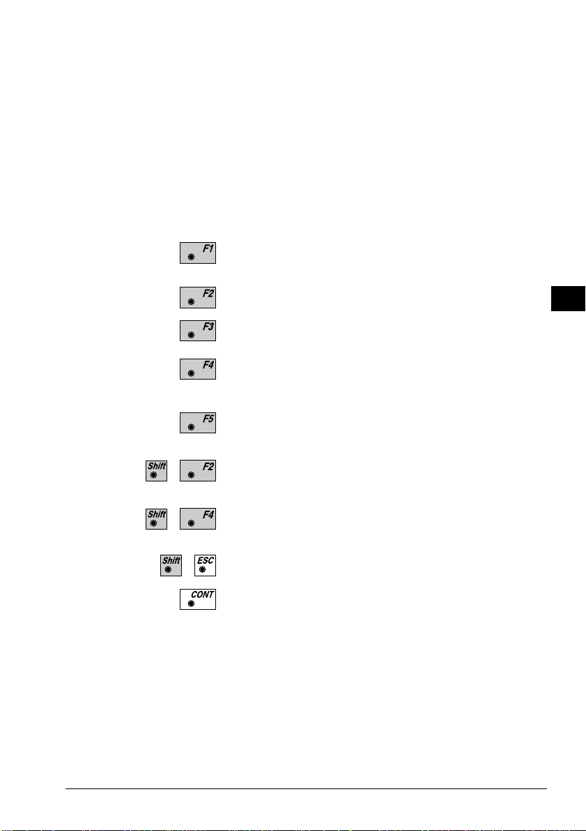
∆ ∆
∆ Height : Difference in height between the
∆ ∆
measured reflector point and the
stakeout point. Positive in sign if
stakeout point is higher than the
reflector position.
IV
Elevation : Elevation of the measured reflector
point.
Simultaneously measure and record data on the active
recording device.
Measure a distance.
Record the measurement on the active recording device.
Enter target data as described in chapter "Measure &
Record" of "System" - user manual.
Re-position the telescope on the target. Note, this
function is only available for motorized theodolites.
Change stakeout method. For more information refer to
chapter "Select Stakeout Method".
Generate a plot of the stakeout data. For more
information refer to chapter "Plot".
EL
AH
OH
BS
SM
SO
Exit the program.
Acquire the next point to stake.
© Leica TPS-System 1000 Programs-2.3.1en 73
Page 75
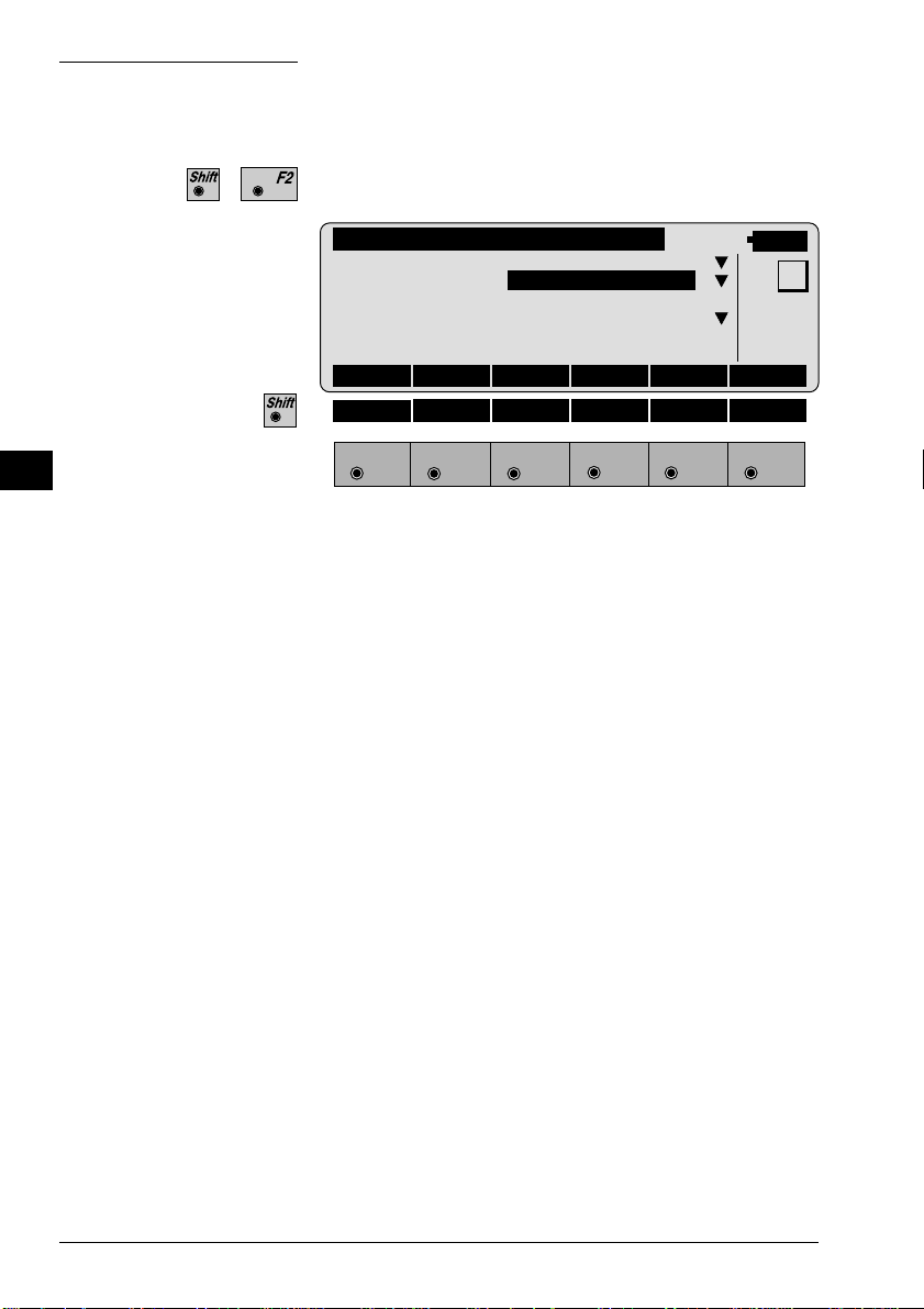
Select Stakeout Method
IV
EL
AH
OH
BS
SM
SO
Select the stakeout method in any stakeout dialog.
STAKE\ SELECT METHOD
Coarse Meth :
Stakeout M. :POLAR STAKEOUT
3D Stakeout. : ON
Position : 2D
Hght. Shift : 0.000 m
LINE OFFSET
14:03
POLAR ORTHO AUX GRID LIST
HELP
F1
F2 F3
F4
F5 F6
Coarse Meth :
Select the method for "COARSE POSITIONING":
NONE no static method used
LINE OFFSET see chapter "Line Offset"
ORTHOGONAL see chapter "Orthogonal"
AZIMUTH & DIST A N see chapter "Azimuth and
Distance"
Choosing NONE, the program will automatically
proceed to the selected "STAKEOUT METHOD" and
bypass the "COARSE POSITIONING" method after
you selected a new stakeout point.
MC
Stakeout M. :
Select the method for "STAKEOUT":
POLAR STAKEOUT see chapter "Polar
Stakeout"
ORTHOGONAL ST AKE see chapter "Orthogonal
Stakeout"
AUXILIARY POINTS see chapter "Stakeout with
auxiliary points"
GRID COORDINA TES see chapter "Stakeout from
Coordinate Differences"
74 TPS-System 1000 Programs-2.3.1en © Leica
Page 76
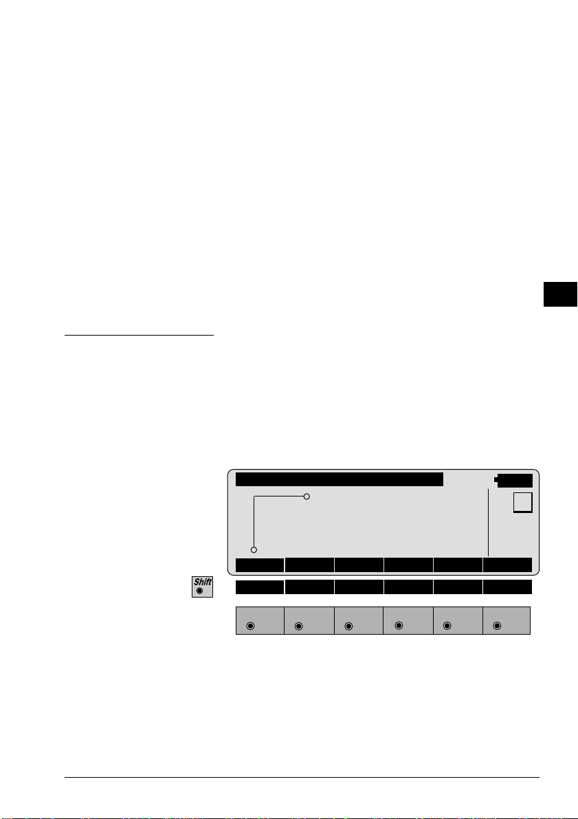
3D Stakeout : ON for 3D stakeout,
OFF for 2D stakeout.
Position : Select positioning method. (Motorized
instruments only):
Off Automatic positioning off
2D Positioning of the horizontal
drive
3D Positioning vertical and
horizontal drive
Hght. Shift : All heights are changed by this
amount. The value can be changed
only when you are in this dialog.
IV
EL
AH
OH
BS
SM
SO
Plot
A plot is generated of the stakeout situation with a list
of the numeric values, corresponding to the
"STAKEOUT METHOD".
Note, below a typical plot is shown using the coordinate
"STAKEOUT METHOD".
STAKE\ PLOT
∆E PS
∆N
R
∆E : 0.024 m
∆N : 0.012 m
14:03
MC
HELP
F1
F2 F3
F4
F5 F6
© Leica TPS-System 1000 Programs-2.3.1en 75
Page 77
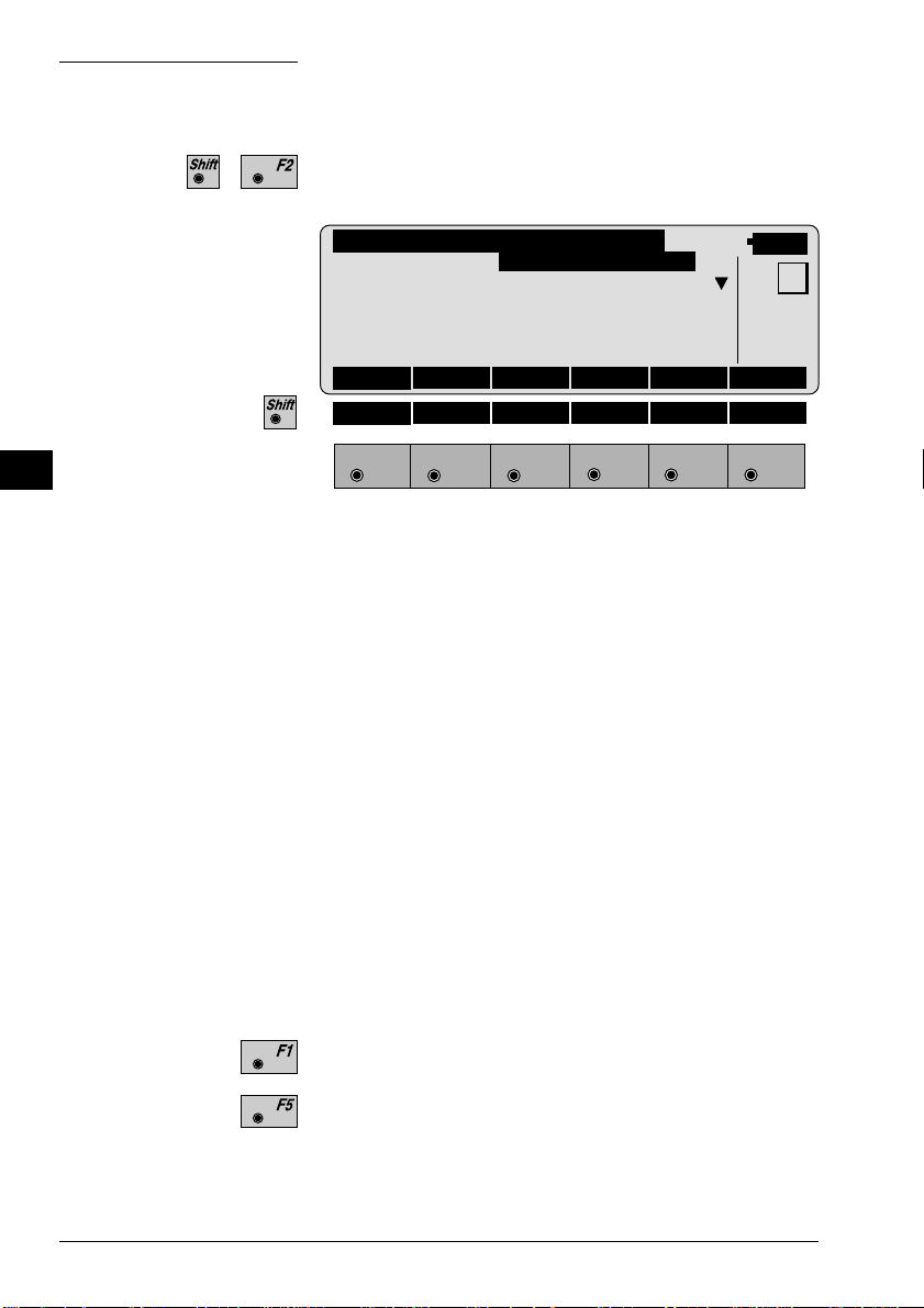
Configuration
IV
EL
AH
OH
BS
SM
SO
Start the "Configuration Editor" from the "SEARCH
POINT" dialog.
STAKE\ CONFIGURATION
3D Stake : ON
Log File : OFF
Log FlName : STAKEOUT.LOG
14:03
INFO DFLT OFF
HELP
F1
F2 F3
F4
F5 F6
The "Configuration Editor" sets parameters for further
program operations:
3D Stake : ON for 3-dimensional stakeout.
Note the program will not perform 3D
stakeout if no elevation is available
for the point to be staked.
OFF for 2-dimensional stakeout.
Note that there will be no difference in
height displayed.
MC
Log File : OFF no recording in a Log file
SHORT reduce recording in a Log
file
LONG detailed recording in a Log
file
Display software-version
Set the value to default. (3D stake = ON).
76 TPS-System 1000 Programs-2.3.1en © Leica
Page 78
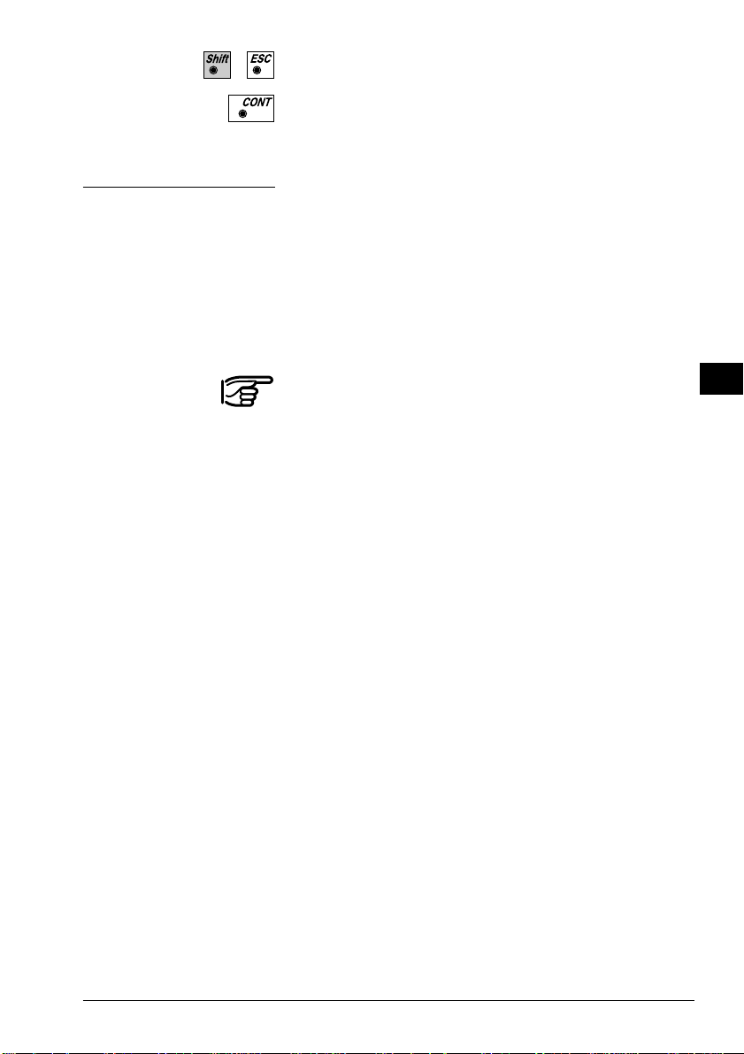
Log File
Exit the program.
Store the current configuration and proceed to the
dialog "SEARCH POINT".
If "Log File" is set to "ON" the measurements and the
results are stored in the ASCII-file specified within the
"Configuration Editor". This file is created in the
directory LOG on the memory card. Subsequently, you
can read the memory card on your PC and obtain a hard
copy of the Log-file.
IV
EL
AH
OH
BS
SM
Data will always be appended to the specified Log-file.
The Log-file contains the following information:
Header The header line will contain the
program used, information about the
instrument, the name of the data file as
well as date and time.
Record SHORT recording of design
coordinates, setout height and height
difference in the log file.
LONG recording of design
coordinates, setout coordinates und
differences of coordinates in the log
file.
SO
© Leica TPS-System 1000 Programs-2.3.1en 77
Page 79

Leica VIP Stakeout V 2.10
Instrument : TCM1100, Serial 412160, (not named)
User templ. : User 1
Meas. file : FILE12.GSI
IV
Program Start : 09/04/1996 at 01:18
EL
AH
OH
BS
SM
SO
Station no. : 3000
E= 21.016m N= 64.666m ELV= 420.467m hi= 1.700m
Point no. : 1152, Hght. Shift = 0.000m
Design : E= 21.602m N= 62.184m ELV= 420.115m
Staked : E= 21.606m N= 62.166m ELV= 420.355m hr= 1.500m
Deltas : dO= -0.004m dN= 0.018m dELV= -0.240m
Typical log file entry in the "STAKEOUT" program
78 TPS-System 1000 Programs-2.3.1en © Leica
Page 80

Free Station
Introduction
This manual describes the "FREE STATION" program
of the TPS SYSTEM 1000 theodolite series.
Pt1
H
N
Pt2
Pt3
E0
PROG_Z19
N0
E
This program can be used to deduce the three-dimensional coordinates for the instrument station and the
horizontal orientation of the from measurements to a
maximum of 10 target points.
For simultaneous determination of the station elevation,
height of instrument and height of reflector must
already have been input and the elevation of the target
points must be known.
IV
EL
AH
OH
BS
SM
AS
FS
The program allows measurement in single or dual-face
mode.
Directions to target points can be determined, as can
any combination of direction and distance. To compute
the position coordinates, at least three elements (2
directions and 1 distance) are necessary.
© Leica TPS-System 1000 Programs-2.3.1en 79
Page 81

Station Data
Enter station point number and height of the instrument.
IV
EL
AH
OH
BS
SM
AS
FS
Target Point
FREST\ STATION DATA
14:03
Station no. : 1
Inst.Height : 1.555 m
HELP CONF
F1
F2 F3
F4
F5 F6
Proceed to define the target points.
Start the "CONFIGURATION"
Alpha-numerical/numerical input.
Enter the target point number and height of the
reflector.
MC
αNUM
FREST\ TARGET POINT
Station no. : 1
Refl.Height: 1.555 m
14:03
MC
CALC LIST <-- --> αNUM
HELP
F1
F2 F3
F4
F5 F6
Run the calculation. Note, the key will be
assigned after sufficient measurements were taken to
calculate a position.
80 TPS-System 1000 Programs-2.3.1en © Leica
Page 82

Entry of target points into a list as well as selecting
points for further use.
Displays the previous point from the list of points you
entered. Note that this key will not be available until
there is at least one point in the list.
Displays the next point in the list of points you entered.
Note that this key will not be available until there is at
least one point in the list.
IV
EL
AH
OH
Point List
Retrieve the coordinates of the target point from the
active file. For further information, please refer to
dialog "IMPORT" described in the "SYSTEM" - user
manual.
Alpha-numerical/numerical input.
Enter a maximum of 10 points. The same point can be
retrieved several times.
The same point number can be used several times
without new input.
FREST\ POINT LIST
14:03
Point 1 TAR01
Point 2 TAR02
Point 3 TAR03
Point 4 TAR04
Point 5 TAR05
Point 6 TAR06
Point 7 TAR07
Point 8 TAR08
Point 9 TAR09
Point10 TAR10
BS
SM
AS
FS
MC
HELP
F1
F2 F3
F4
F5 F6
Return to the dialog "Target Point".
© Leica TPS-System 1000 Programs-2.3.1en 81
Page 83

Measure Mode
IV
EL
AH
OH
This dialog is similar to the TPS System 1000’s basic
"MEASURE MODE" dialog. Once a measurement is
taken, the program will return to the dialog "DEFINE
POINT" to acquire the next point for measuring.
If the station coordinates can be calculated successfully
from the first few measurements, the ∆ Hz and ∆V
values are displayed for further entered target points.
Motorized theodolites will automatically drive the
telescope to the target point.
BS
SM
AS
FS
FREST\MEASURRE MODE (GSI)
Point no. : 12
Hz : 286°55'50"
V : 91°16'20"
Refl.Height : 1.500 m
Slope Dist. : 22.039 m
∆Hz : -----
14:03
MC
ALL DIST REC TARGT
HELP I<>II
F1
F2 F3
F4
F5 F6
Simultaneously measure and record data on the active
recording device. Return to the dialog "TARGET
POINT".
Measure a distance.
Record the measurement on the active recording device.
Return to the dialog "TARGET POINT".
Enter target data. For further information, please refer
to chapter "Measure & Record" described in the
"System" - user manual.
Change the theodolite face.
Call up the CODE function, as described in chapter
"Measure & Record" described in the "System" - user
manual.
Exit the program.
Accept the measurement and return to the dialog
"TARGET POINT".
82 TPS-System 1000 Programs-2.3.1en © Leica
Page 84

Calculation
Calculates the 3D station coordinates and orientation as
well as the standard deviation of the results.
FREST\ RESULTS <L.SQRS>
Station no. : 1
No. of Pts : 6
Inst.Height : 1.635 m
Easting : 2134.234 m
Northing : 4231.365 m
Elevation : 580.643 m
14:03
SET STORE PLOT MORE
Orientation : 2°12'34"
σEasting : 0.003 m
σNorthing : 0.005 m
σElevation : 0.005 m
σOrient : 0°00'03"
Calc Scale : YES
Scale : 0.999956
HELP ROBST
F1
F2 F3
F4
F5 F6
Station no : Point number assigned to the station
No. of Pts : Number of points measured
Inst.Height : Instrument Height
Easting : Calculated Easting for the station
MC
IV
EL
AH
OH
BS
SM
AS
FS
Northing : Calculated Northing for the station
Elevation : Calculated Elevation for the station
Orientation : Oriented direction
σσ
σ Easting : Standard deviation of Easting
σσ
σσ
σ Northing : Standard deviation of Northing
σσ
σσ
σ Elevation : Standard deviation of the Elevation
σσ
© Leica TPS-System 1000 Programs-2.3.1en 83
Page 85

IV
EL
AH
OH
σσ
σ Orient : Standard deviation of the Orientation
σσ
Calc Scale : YES scale factor is calculated,
NO scale factor is not calculated
Scale : The scale factor of the free station
calculation.
Note that the scale is not shown if
set to NO.
BS
SM
AS
FS
Set orientation and station coordinates on the
instrument. Note that this key will end the program.
Record the following results on the active recording
device:
WI 11 Station Point Number
WI 25 Orientation correction
WI 84 Station Easting
WI 85 Station Northing
WI 86 Station Elevation
WI 87 Last reflector height used
WI 88 Instrument Height
Sketch of the station and the reference points used.
Show the results of individual measurements on the
screen (see dialog "More Information").
Measure more points. The program will recall the
"TARGET POINT" dialog.
Select between the "Robust" method and the "Variation" method
Exit the program.
84 TPS-System 1000 Programs-2.3.1en © Leica
Page 86

More Information
Display the residuals of individual measurements. You
can also disable points from the calculation of position
or height as well as delete erroneous measured points.
IV
FREST\MEHR INFORMATIONEN
Use for Ht :YES Status: ON
Point no. : 12
Error Flag : NONE
∆ Hz : 0°00'03"
∆ Distance : 0.050 m
14:03
9/10
RECLC <-- --> MEAS DEL NO
∆ Height : 0.020 m
Refl.Height : 1.555 m
Easting : 991.427 m
Northing : 1995.162 m
Elevation : 402.466 m
HELP
F1
F2 F3
F4
F5 F6
9/10 : Sequence number of the current point
and total number of points in the
measurement set. The scroll bar shows
the sequential position of the
measurements, graphically.
Use for Ht. : Use this measurement for height
determination (YES/NO)
MC
EL
AH
OH
BS
SM
AS
FS
Status : Use this measurement for calculation
(ON/OFF).
Point no : The target point number.
Error Flag : Identified erroneous measurements.
Possible values are:
NONE measurement is OK
HZ horizontal angle error
DIST distance error
HT height difference error
The flags may also be combined, i.e.
DIST + HZ
© Leica TPS-System 1000 Programs-2.3.1en 85
Page 87

IV
EL
AH
OH
BS
SM
∆∆
∆ Hz. : Difference between calculated and
∆∆
measured Hz. angle
∆∆
∆ Distance : Difference between calculated and
∆∆
measured distance
∆∆
∆ Height : Difference between calculated and
∆∆
measured height
Refl. Ht. : Reflector height used for that target
point
Easting, Northing, Elevation : Ta rget coordinates
used.
AS
FS
Recalculate the result.
Scroll to the measurements of the previous point.
Scroll to the measurements of the following point.
Measure more point. Return to dialog "TARGET
POINT".
Delete a point from the set of measurements . You can
now measure a new point in its place.
Exit the program.
86 TPS-System 1000 Programs-2.3.1en © Leica
Page 88

Plot
Generates a plot showing the measurement
configuration. The station point is in the center and the
top of the sketch shows the direction of Grid north. The
sketch is true in angular but not true in distances. Points
are numbered sequentially in the order in which they
were measured. Points not used in the calculation are
marked with a dotted line.
IV
EL
AH
FREST\ PLOT
2
3
4
1
5
RECLC MEAS
14:03
MC
OH
BS
SM
AS
HELP
F1
F2 F3
F4
F5 F6
FS
Recalculate the solution and return to the dialog
"CALCULATION RESULTS" (see page 83).
Measure more points. The program will recall the
"TARGET POINT" dialog. (see page 80).
...
T oggle any point ON or OFF by pressing the numeric
key corresponding to the sequence number of the point.
Note, that represents point 10.
© Leica TPS-System 1000 Programs-2.3.1en 87
Page 89

Configuration
IV
Configuration Editor
EL
AH
Start the "Configuration Editor" from the "STATION
DA TA" dialog.
OH
BS
SM
AS
FS
FREST\ CONFIGURATION
Hz Ori Acc : 0°00'32"
Ht Acc TP : 0.0250 m
Posn Acc TP : 0.0250 m
Two Faces : NO
User Displ. : NO
Log File : OFF
14:03
INFO DFLT EDIT
Log FlName : FREE_STA.LOG
HELP I<>II
F1
F2 F3
F4
F5 F6
The "Configuration Editor" sets parameters for further
program operations:
Hz Ori Acc : Limit for the standard deviation of the
orientation. The orientation is
regarded as "error free", if the
computed standard deviation of the
orientation is within twice the entered
value.
Ht Acc TP : Height accuracy of the target points.
The entered value, is used as an "a
priori" accuracy in the calculation.
The height is regarded as "error free",
if the computed standard deviation is
within twice the entered value.
MC
88 TPS-System 1000 Programs-2.3.1en © Leica
Page 90
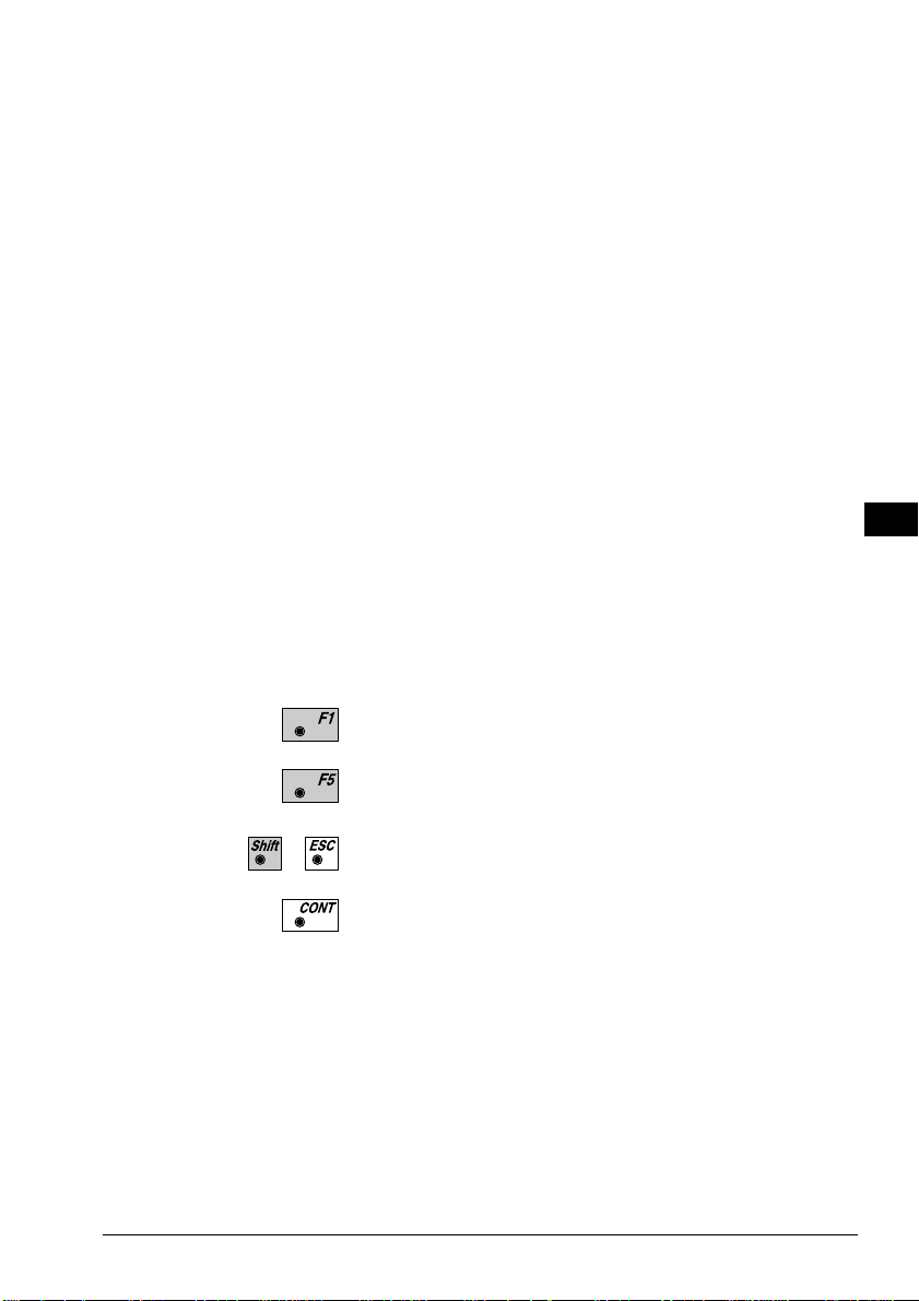
Posn Acc TP : Position accuracy of the target points.
The entered value, is used as an "a
priori" accuracy in the calculation.
The position is regarded as "error
free", if the computed standard
deviation is within twice the entered
value.
IV
EL
Two Faces : YES for dual-face measurement,
NO for single-face.
User Disp : YES; the measured value indication is
used from application "Measure and
record".
NO; the default indication is used for
the "Free Station".
Log File : ON, records measurements in a Log-
File.The format is described on page
90.
Log FlName : Enter the Log File Name
Display software-version
Set the values to default. Default values are shown in
the previous dialog.
Exit the program.
AH
OH
BS
SM
AS
FS
Store the current configuration and proceed to the
dialog "STATION DATA".
© Leica TPS-System 1000 Programs-2.3.1en 89
Page 91

Dual-face Measurement
IV
EL
AH
OH
BS
SM
Log File
AS
FS
In the dual-face mode, the program will prompt for
measurements in both faces. When both measurements
are taken, the program will check the difference
between the two. If the difference in angle is within 27'
(0.5 gon) and the difference of two measured distances
is within 0.5 m (1.64 ft), the observations will be
averaged. These tolerances are used to avoid errors in
target identification. If exceeded an error message will
be displayed.
If "Log File" is set to ON the measurements and the
results are stored in the ASCII-file specified within the
"Configuration Editor". This file is created in the
directory LOG on the memory card. Subsequently, you
can read the memory card on your PC and obtain a hard
copy of the Log-file.
Data will always be appended to the specified Log-file.
The Log-file contains the following information:
Header The header line will contain the
program used, information about the
instrument, the name of the data file as
well as date and time.
Record For each measurement, a record will
be stored containing :
- Station coordinates and
- orientation correction,
- standard deviations for
Easting,
Northing,
Height of station
and orientation correction.
90 TPS-System 1000 Programs-2.3.1en © Leica
Page 92

The residuals for
- horizontal angles,
- heights and
- measured distances
are also listed.
IV
EL
Leica VIP Free Station V 2.10
Instrument : TCM1800, Serial 410000, (not named)
User templ. : User 1
Meas. file : FILE01.GSI
Program Start : 02/05/1996 at 11:23
Using Least-Squares Solution
Station no. : 200
E= -3.5461m N= -0.7683m ELV= -0.6518m hi= 0.0000m
Ori.Corr. : 0°00'20"
S.Dev. East : 0.0003m
S.Dev. North : 0.0003m
S.Dev. Elev. : 0.0015m
S.Dev. Orient. : 0"00'02"
4 point(s) measured :
## Point no. d Hz d Height d Distance Error Flag
1 109 0°01'21" 0.0012m -0.0000m NONE
2 110 -0°00'00" -0.0045m -0.0002m NONE
3 112 -0°00'25" 0.0018m 0.0010m NONE
4 113 0°00'48" 0.0014m -0.0002m NONE
Continued next page
AH
OH
BS
SM
AS
FS
© Leica TPS-System 1000 Programs-2.3.1en 91
Page 93

IV
EL
AH
Using Robust Solution
Station no. : 200
E= -3.5461m N= -0.7683m ELV= -0.6518m hi= 0.0000m
Ori.Corr. : 0°00'20"
S.Dev. East : 0.0003m
S.Dev. North : 0.0003m
S.Dev. Elev. : 0.0015m
S.Dev. Orient. : 0°00'02"
OH
BS
SM
AS
FS
4 point(s) measured :
## Point no. d Hz d Height d Distance Error Flag
1 109 0°01'21" 0.0012m -0.0000m NONE
2 110 -0°00'00" -0.0045m -0.0002m NONE
3 112 -0°00'25" 0.0018m 0.0010m NONE
4 113 0°00'48" 0.0014m -0.0002m NONE
Typical log file entry in the "FREE STATION" program
92 TPS-System 1000 Programs-2.3.1en © Leica
Page 94
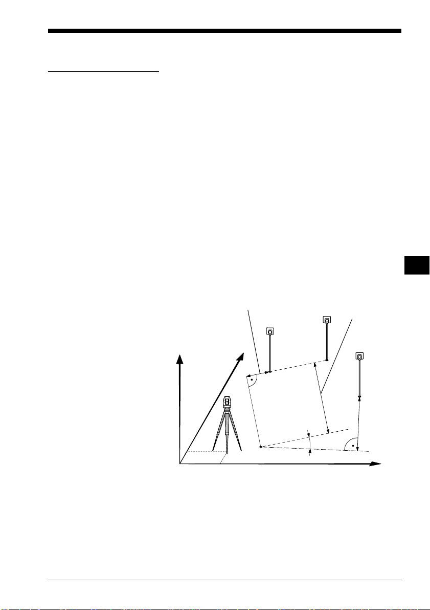
Reference Line
Introduction
This manual describes the "REFERENCE LINE"
program of the TPS SYSTEM 1000 theodolite series.
The distance and the angle between two points is
calculated by the program.
"REFERENCE LINE" is a specialized form of stakeout
used for construction and building alignment. It permits
positioning of a point referred to a line. Points for use in
the program can be measured, entered manually, or read
from the database.
The program records individual measurements in the
database. In addition, the program generates a log file
containing all data for a given measurement session.
Line
Pt1
H
N
Baseline
Pt2
Offset
Target pt
IV
EL
AH
OH
BS
SM
AS
FS
RL
∆Offset
α
PROG_Z12
© Leica TPS-System 1000 Programs-2.3.1en 93
∆Line
Ref.line
E
Page 95
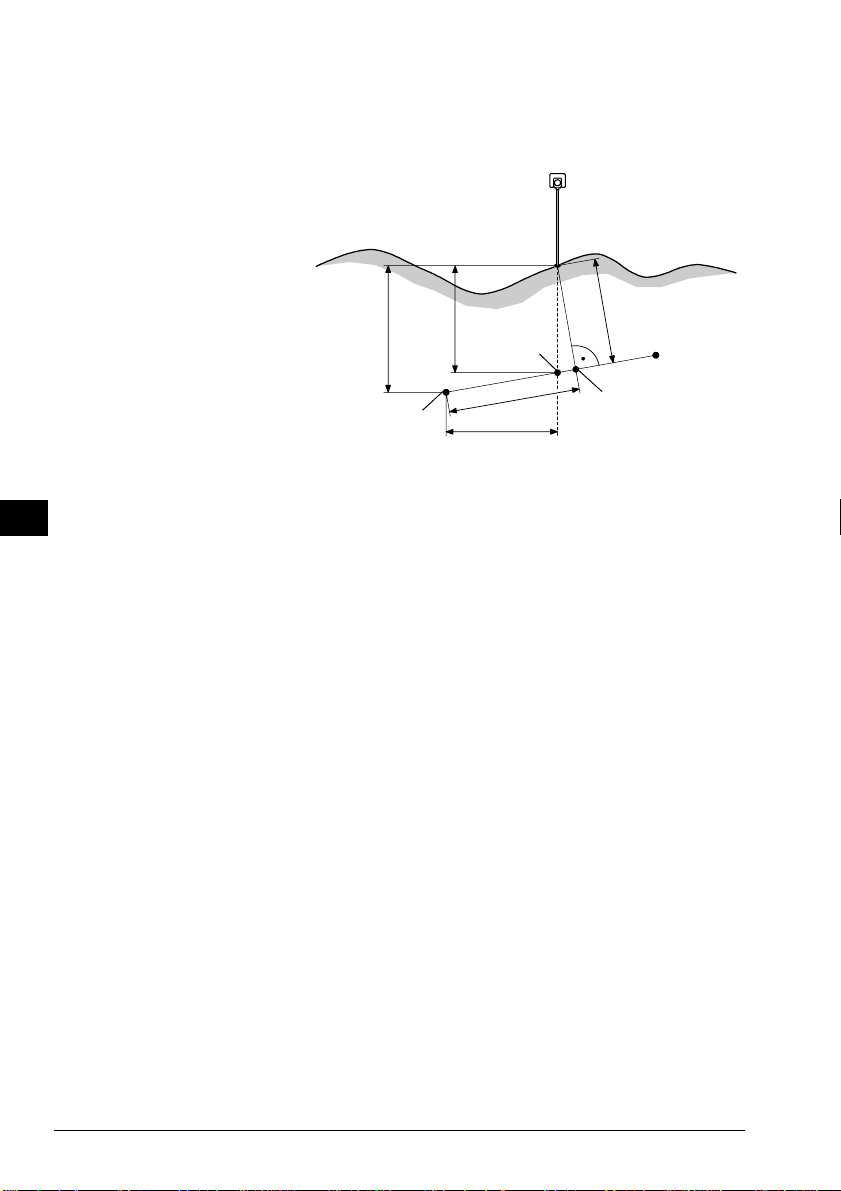
The program also allows to determine various values of
height determination as shown in the figure below.
IV
EL
AH
OH
BS
SM
AS
FS
RL
Target point
PROG_Z12
∆H1 ∆H2
P1
FP
∆Spat.dist
∆Line
∆Offset
P2
NP
FP Point of intersection of vertical with
line P1-P2
NP Point of intersection with line P1- P2
of perpendicular to P1- P2
∆∆
∆H1 Height difference to start of line P1
∆∆
∆∆
∆H2 Height differencein relation to the
∆∆
interpolated height FP of reference
line P1-P2.
∆∆
∆Line Horizontal distance from P1 to FP
∆∆
(abscissa)
∆∆
∆Spat.dist Spatial distance from P1 to NP
∆∆
∆∆
∆Perp.l Length of perpendicular from Target
∆∆
point to Reference line
94 TPS-System 1000 Programs-2.3.1en © Leica
Page 96

Baseline Points
Determine Base Points
or
This dialog defines the two points of the baseline. You
can either manually enter, measure or search for the
point in the database.
REFLN\ REFERENCE LINE
14:03
1. POINT BASELINE
Rec. device : MEMORY-CARD
Search in : FILE01.GSI
Point/Code : 58
INPUT MEAS SEARC αNUM
HELP CONF
F1
F2 F3
F4
F5 F6
Manually enter the first base point. The TPS 1000
manual input dialog will appear.
Proceed to determine the base point by a measurement.
Initiate a search of the point in the database.
Start the "Configuration Editor".
MC
IV
EL
AH
OH
BS
SM
AS
FS
RL
Exit the program.
© Leica TPS-System 1000 Programs-2.3.1en 95
Page 97

Measure a Base Point
IV
This dialog is used in accordance with the settings of
the system function "Measure & Record" or according
to the dialog shown below.
EL
AH
OH
BS
SM
AS
FS
RL
REFLN\ REFERENCE LINE
Puoint no. : 12
Hz : 286°55'50"
V : 91°16'20"
Refl.Height : 1.500 m
Slope Dist. : 22.039 m
Height diff : 2.543 m
14:03
ALL DIST REC TARGT
HELP I<>II
F1
F2 F3
F4
F5 F6
Simultaneously measure and record in the active file.
Proceed with the dialog "1 POINT BASELINE" (page
95). If the second point has already been measured, the
program will proceed to the "DEFINE REF LINE"
dialog.
Measure a distance.
Record the measurement in the active file and proceed
with the dialog "1 POINT BASELINE" (page 95). If
the second point has already been measured, the
program will proceed to the "DEFINE REF LINE"
dialog.
MC
Measure the distance. Accept the measurement without
recording. If the second point has already been
measured, the program will proceed with the "DEFINE
REF LINE" dialog.
Enter the target data. For further information refer to
chapter "Measure & Record" of "SYSTEM" - user
manual.
96 TPS-System 1000 Programs-2.3.1en © Leica
Page 98

Change the theodolite face.
Call up the CODE function, as described in chapter
"Measure & Record" of "SYSTEM" - user manual.
Exit the program.
IV
EL
AH
OH
BS
SM
AS
FS
RL
© Leica TPS-System 1000 Programs-2.3.1en 97
Page 99

Define Reference Line
IV
EL
AH
OH
BS
SM
The reference line can be defined by entering a distance
value, a line offset value and an angle value for the base
line. Heights can be changed by a constant rate (eg, 1m)
by entering a H offset value.
REFLN\ DEFINE REF LINE
1.BasePoint : 12
2.BasePoint : 13
Offset : 1.000 m
Line : 1.558 m
Alpha : 2°03'39"
H Offset : 0.500 m
14:03
MC
NEWL MEAS
HELP
AS
FS
RL
F1
F2 F3
F4
F5 F6
1.BasePoint : The first base point that defines the
base line.
2.BasePoint : The second base point that defines the
base line.
Offset : Establishes the displacement parallel
to the base line.
Line : Establishes the distance from the first
reference point to the starting point of
the new reference line.
Alpha : Establishes the angle between the base
line and the new reference line.
H Offset : Displaces the base line parallel in
height.
Define a new base line.
or
Accept parameters as displayed and proceed to the
"RESULT REF LINE" dialog.
98 TPS-System 1000 Programs-2.3.1en © Leica
Page 100

Results Reference Line
The "RESULTS REF LINE" dialog displays the data of
the measured point refering to the reference line, as
shown in dialog below:
IV
REFLN\RESLUTS REF LINE
Point no. : 12
∆ Offset : 0.020 m
∆ Line : 1.468 m
∆ H : -0.558 m
∆Perp.lngth : 0.039 m
∆Spat. dist : 3.020 m
14:03
ALL DIST REC TAGT
Elevation : 103.020 m
HELP
F1
F2 F3
F4
F5 F6
Point No. : The point number of the stakeout
point.
∆∆
∆ Offset : The delta value of line Offset in
∆∆
reference to the stakeout point.
(ordinate)
∆∆
∆ Line : The delta value of Line in reference
∆∆
to the stakeout point. (abscissa)
∆ ∆
∆ H : Height difference between the
∆ ∆
stakeout point as measured and the
height reference point.
MC
EL
AH
OH
BS
SM
AS
FS
RL
∆∆
∆Perp.lngth. : Length of perpendicular
∆∆
∆∆
∆Spat.dist. : Spatial distance
∆∆
Elevation : Height of target point.
If "∆Offset" is brought to "0" by turning the instrument,
a distance measurement must always be carried out for
control purpose.
© Leica TPS-System 1000 Programs-2.3.1en 99
 Loading...