

Page 1
WMFB-1 & WMFB-2 SERIES FLOOR BOX
-
-
-
-
Ø
Ø
INSTALLATION INSTRUCTIONS
NOTICE: READ BEFORE INSTALLING DEVICE
FEATURES AND BENEFITS
• Exclusive Dual Voltage Single Gang Floor Box, great for TV’s,
Telephones and Laptop connections
• Complete line of low voltage connectors available through
Pass and Seymour (www.passandseymour.com).
• Installs before or after the floor is completed to ensure the best
possible finish
Available Catalog #’s
Cat # Description
WMFB1DR* 1 gang floor box, Duplex Cover, Duplex 15 amp Receptacle
WMFB1KS2* 1 gang floor box, Single Cover, Two Port Keystone Jack
WMFB1KS4* 1 gang floor box, Duplex Cover, Four Port Keystone Jack
WMFB1SR* 1 gang floor box, Single Cover, Single 15 amp Receptacle
WMFB1SRKS1* 1 gang floor box, Duplex Cover, Single 15 amp Receptacle &
WMFB2DR2* 2 gang floor box, Two Duplex Cover, Two Duplex 15 amp
WMFB2DRKS4* 2 gang floor box, Two Duplex Cover, Duplex 15 amp Receptacle
WMFB2KS8* 2 gang floor box, Two Duplex Cover, Two 4 Port Keystone Jack
1. WARNING: TEST THAT POWER IS OFF AT CIRCUIT BREAKER OR
FUSE BLOCK!
2. Determine approximate location (which joists to put it between) and
route cable(s) to joist cavity and fasten cable within 12" of proposed
opening per NEC 334.30 leaving large enough loop to later install box
after finishing floor installation.
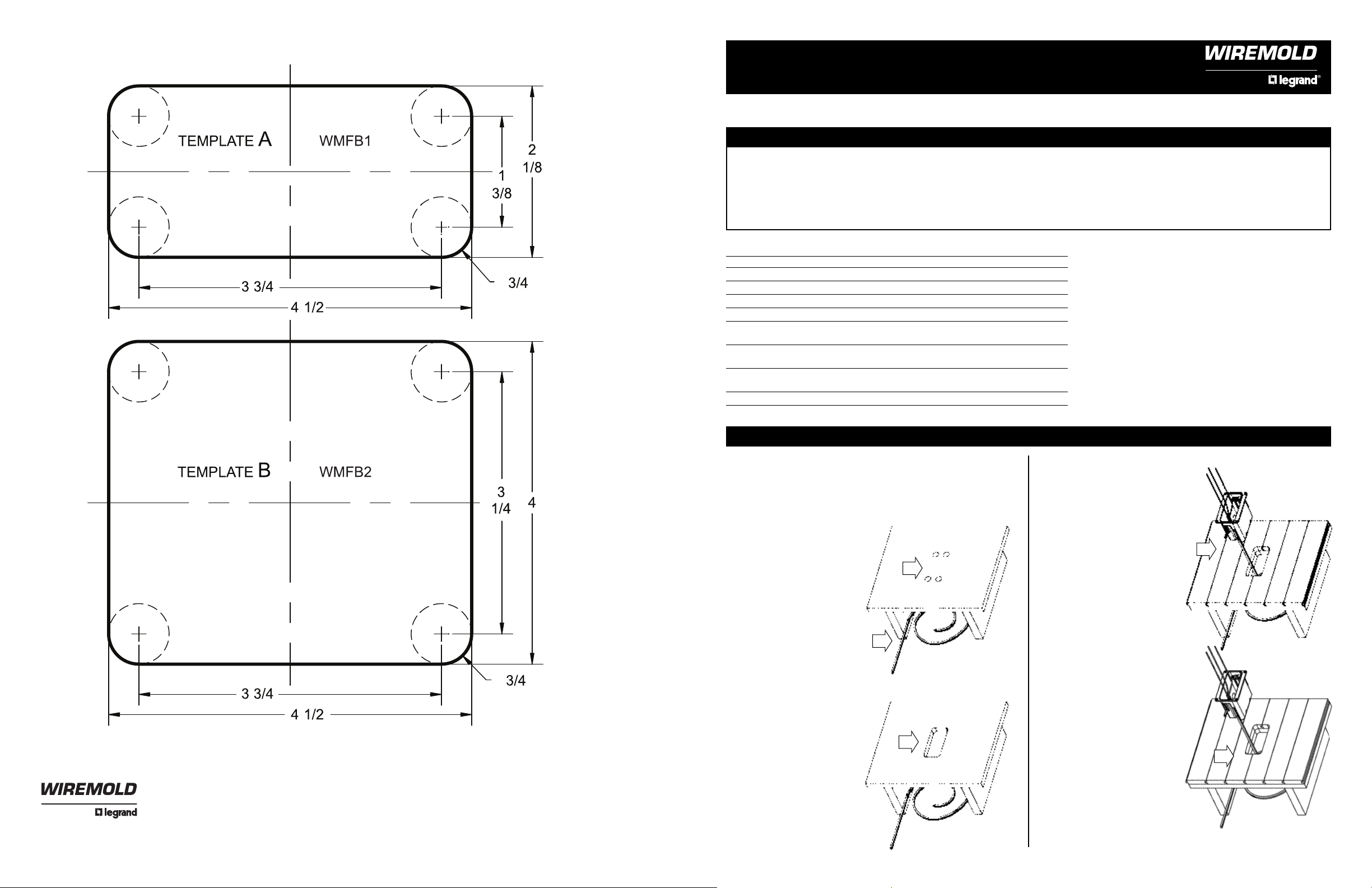
3. Determine box location and
drill four 3/4" diameter holes
using template “A” for
WMFB1 series or template
“B” for WMFB2 series.
Note: When installing tile,
marble or hardwood flooring,
you may want to wait to cut
the opening during the
finished floor installation to
ensure the opening in the
floor does not end up in the
middle of a tile or hardwood
plank.
4. Cut remainder of opening
using the appropriate template by connecting the
edges of the holes.
5. Complete the finished floor
installation up to the
previously cut opening,
ensuring the box will still fit
into opening.
1 Port Keystone Jack
Receptacles
& 4 Port Keystone Jack
*denotes: B = Brass Cover or N = Nickel Plated Cover
NEW/OLD CONSTRUCTION
3
2
4
• Easy rectangular floor cut out
• Swing bracket mounting option, superior for tile or marble floors
• No messy caulking needed to meet scrub water requirements
• Plastic Boxes do not require ground bonding in most applications
NOTICE: For installation only by a electrician or other
qualified person in accordance with the National Electrical
Code, Canadian Electrical Code, local Codes and the
instructions on this sheet.
CAUTION: RISK OF ELECTRICAL SHOCK. Turn off all power
to circuit before installing this device. Improper wiring of any
electrical device can cause serious injury or death.
CAUTION: Connect only copper or copper-clad wire to the
device in this package. Do not connect aluminum wire to this
device.
NOTE: USE ONLY ELECTRICAL MOUNTING BOX
PROVIDED.
6. Pull the wires through the
opening in floor and into the
auto-clamp feature. Knockouts are provided for low
voltage cables if desired. If
Romex-type NM cable is
routed through the knockouts,
an approved wire clamp must
be used.
7. Attach box to flooring using
either the four #6 drywall
screws included or use the
assembled swing brackets.
Tighten screws firmly. When
assembling to carpet, the
carpet may need to be
trimmed back to ensure the
box flange sets flush. Trim only
the carpet loops/shag and
leave the carpet backing under
the flange for security. Cut the
padding back 1-2" larger than
the opening to ensure the
device seats firmly and flush to
the floor.
8. Install device(s) per appropriate
installation instructions below.
6
7
U.S. and International: 60 Woodlawn Street • West Hartford, CT 06110 • 1-800-621-0049 • FAX 860-232-2062 • Outside U.S.: 860-233-6251 P/N 340771 Rev. B
Canada: 570 Applewood Crescent • Vaughan, Ontario L4K 4B4 • 1-800-723-5175 • FAX 905-738-9721
www.wiremold.com Printed in USA
Page 2
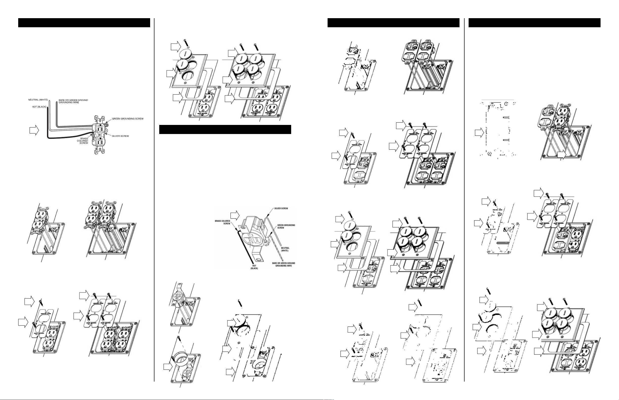
DUPLEX RECEPTACLE(S)
INSTALLATION INSTRUCTIONS
This device should be installed in accordance with all appropriate codes
and standards. Warning: Turn off power to outlet box, using breaker or
fuse at service entrance. Verify that power has been removed by testing
with a circuit tester at the outlet box. Caution: This device is for use with
copper or copper-clad wire only.
A. After removing power as described above, use strip gauge on back of
outlet to strip all wires to desired length.
B. Attach wires according to the following diagram. Be sure the wires are
fastened securely either by the terminal screws or through the
speed-wire holes in the back of the outlet. Loosely fastened wires may
result in outlet failure and/or fire hazard. Attach wires using terminal
screws or speed-wire holes: Not both!
H. Assemble o-rings to the provided #6-32 x 1" oval head screws and
use these to assemble the cover plate to the box. Torque to
approximately 10 in/lbs ensuring the gasket stays in place under the
cover plate.
H
H
H
H
G
G
DATACOM KEYSTONE TWO & FOUR PORT
KEYSTONE JACKS
A. See the instructions enclosed with the product for specific wiring.
B. Mount the device in box by sandwiching the device to the box with the
intermediate sub-plate using provided #6-32 x 3/4" pan head
mounting screws. Note: Orient the Sub-plate to say “THIS SIDE UP”.
For the two port, attach the device to the boxby screwing the strap directly
to the box using provided #6-32 x 3/4" pan head mounting screws.
COMBO RECEPTACLE/KEYSTONE
This device should be installed in accordance with all appropriate codes
and standards. Warning: Turn off power to outlet box, using breaker or
fuse at service entrance. Verify that power has been removed by testing
with a circuit tester at the outlet box. Caution: This device is for use with
copper or copper-clad wire only.
A. After removing power as described above, use strip gauge on back of
outlet to strip all wires to desired length.
B. Attach wires according to the diagram below. The terminal screws
accept up to #12 AWG wire. Loop wires around screws in a
counterclockwise fashion. Fasten terminal screws securely. Loosely
fastened wires may result in outlet failure and/or fire hazard.
C. Ensure divider is in place in box to separate high voltage from low
voltage. WARNING: FAILURE TO INSTALL DIVIDER CAN CAUSE
FIRE, SERIOUS INJURY OR DEATH.
B
C. If using terminal screws: Terminal screws accept up to #12 AWG
wire. Loop wires around screws in a counterclockwise fashion. Fasten
terminal screws securely.
D. If using speed-wire holes: Fully insert #14 AWG solid copper wire
only into the speed-wire holes. Do not use speed-wire holes for
circuits greater than 15 amps. If outlet must be removed, insert
screwdriver blade in the release slot and push it toward the front of the
outlet, releasing the wire. Discard the outlet.
E. Use feed through wires only when wiring to another outlet downstream.
F. Mount the outlet to the box by sandwiching the device to the box with the
intermediate sub-plate using provided #6-32 x 3/4" pan head mounting
screws. Note: Orient the Sub-plate to say “THIS SIDE UP”.
SINGLE RECEPTACLE
This device should be installed in accordance with all appropriate codes
and standards. Warning: Turn off power to outlet box, using breaker or
fuse at service entrance. Verify that power has been removed by testing
with a circuit tester at the outlet box. Caution: This device is for use with
copper or copper-clad wire only.
A. After removing power as described above, use strip gauge on back of
outlet to strip all wires to desired length.
B. Attach wires according to the diagram below. Be sure the wires are
fastened securely by the terminal screws.
Loosely fastened wires may result in outlet failure and/or fire hazard.
Terminal screws accept up to #12 AWG wire. Loop wires around
screws in a counterclockwise fashion. Fasten terminal screws securely.
C. Mount the outlet in box by
screwing the strap directly
to the box using provided
#6-32 x 3/4" pan head
mounting screws.
D. Place the shell over the
single receptacle.
E. Place gasket over the box
flange.
F. Assemble o-rings to the
provided #6-32 x 1" oval
head screws and use these
to assemble the cover
plate to the box. Torque to
10 in/lbs ensuring the
gasket stays in place under
the cover plate.
B
B
B
B
B
C. Place gasket over the box flange.
D. Assemble o-rings to the provided #6-32 x 1" oval head screws and
use these to assemble the cover plate to the box. Torque to 10 in/lbs
ensuring the gasket stays in place under the cover plate.
D
D
D
D
C
C
C
C
D. Assemble the desired Keystone Jack to the strap and wire per the
instructions enclosed with the product.
E. Attach the device to the box by screwing the strap directly to the box
using provided #6-32 x 3/4" pan head mounting screws. Note: Orient
the Sub-plate to say “THIS SIDE UP”.
E
E
E
E
F. Place gasket over the box flange.
G. Assemble o-rings to the provided #6-32 x 1" oval head screws and
use these to assemble the cover plate to the box. Torque to 10 in/lbs
ensuring the gasket stays in place under the cover plate.
F
F
F
G. Place gasket over the box flange.
F
D
F
B
D
F
B
C
C
E
G
G
G
G
F
F
 Loading...