

Page 1
Products Covered:
829PFL (With extensions designating color)
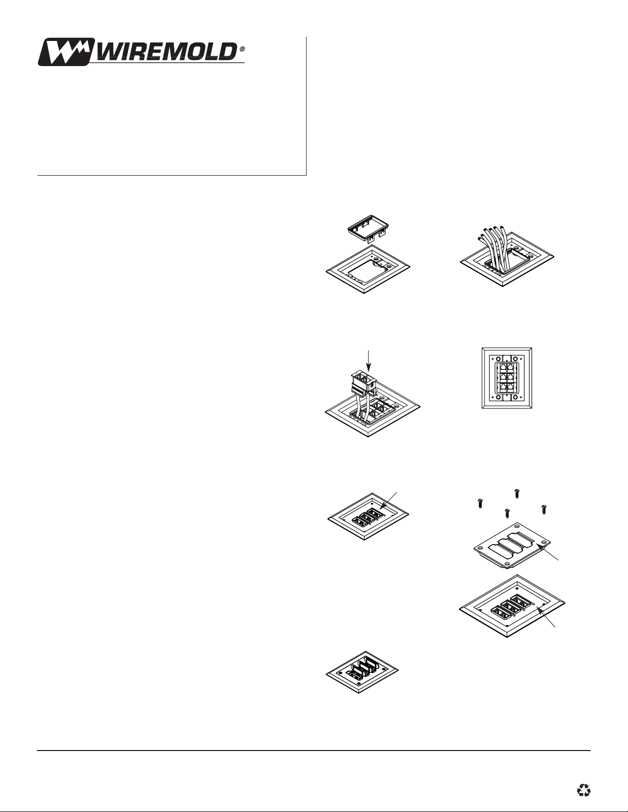
1. Snap Activate™bezel (provided with
cover) into center opening of trim
flange (see Figure 1).
2. Run communication cables through
the opening of the bezel and connect
to Activate inserts (ordered separately)
(see Figure 2).
3. Snap Activate inserts in Activate bezel
(see Figure 3). Cat 5 inserts must be
snapped in the following manner (see
Figure 4). All other inserts may be
snapped in any order.
4. Place the gasket on top of the bezel
so that openings in the gasket align
with the top of the inserts.(see Figure 5).
5. Place the cover over the gasket and align
openings in the cover to the openings in
the gasket. Hinge pins on cover should
align with the depressions in the gasket
(see Figure 6).
6. Tighten the cover to the flange using the
four flat head mounting screws provided.
7. Activate inserts by snapping the cover
doors into the upright position using a
fingernail or blade of a flat head screwdriver (see Figure 7).
8. To close doors, snap doors into the shut
position and press down firmly on the top
of the doors to ensure the correct seal of
door to gasket.
829PFL
Communication Cover Plate
INSTALLATION INSTRUCTIONS
Walker®electrical systems conform to and should
be properly grounded in compliance with requirements of the current National Electrical Code or
codes administered by local authorities.
All electrical products may present a possible
shock or fire hazard if improperly installed or
used. Walker electrical products may bear the
mark as UL Listed and/or Classified and should
be installed in conformance with current local
and/or the National Electrical Code.
Walker Systems, Inc.
A Wiremold Company, Williamstown, WV 26187
1 000 330 999
Figure 1
Figure 2
Figure 7
Figure 5
Figure 6
Figure 3
Figure 4
Activate Insert
(Ordered Separately)
Hinge Pin
Gasket
Depression
© Copyright 1999 The Wiremold Company All Rights Reserved
WALKER INFLOOR SYSTEMS
®
 Loading...