

Walkerduct Pro Series
Wiremold/Legrand electrical systems conform to and should
be properly grounded in compliance with requirements of the
current National Electrical Code or codes administered by
local authorities.
All electrical products may present a possible shock or fire
hazard if improperly installed or used. Wiremold/Legrand
electrical products may bear the mark as UL Listed and/or
Classified and should be installed in conformance with
current local and/or the National Electrical Code.
Round Flush Cover Plates
I N S T A L L A T I O N I N S T R U C T I O N S
Installation Instruction No.: 1 002 970R1 – Updated May 2009
Products Covered: PSRC9TC, PSRC9AMDTC, PSRC9AMDRTTC, PSRC9FFTC, & PSRC9FF2TC
CAUTION: Do not operate tile stripper or resurfacing equipment over top of covers. This may result in damage to the finish of the product.
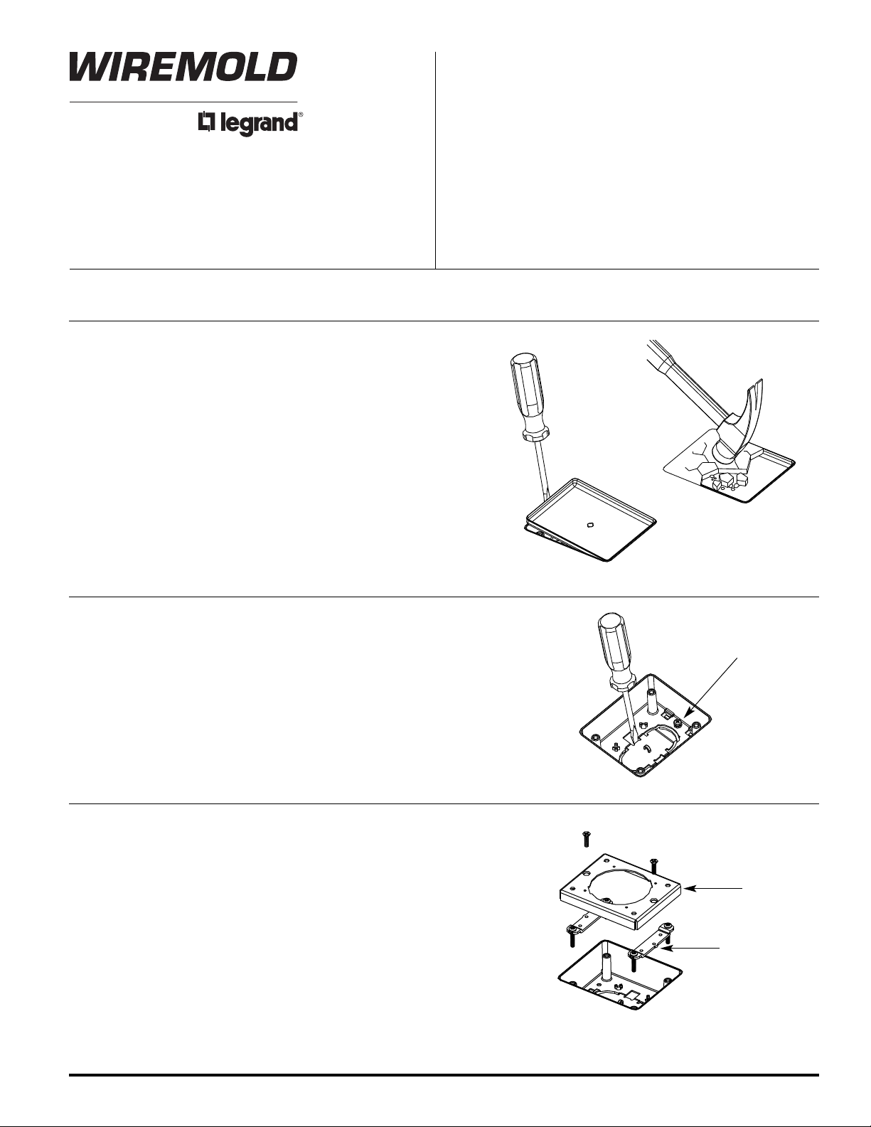
PRESET LOCATION:
1. Determine location of preset cover by measuring (when layout is
known) or by using an electronic preset finder (Cat. No. 480).
Cut and remove carpeting or tile over preset. Carpet may be
saved for later abandoning.
2. Using a hammer, chip out the concrete from the mud cap cover.
3. Strike the edge of the exposed mud cap with a blade type
screwdriver to deflect the cap inward.
4. Insert the screwdriver along the edge of the preset and pry up
removing the cap.
5. Remove any debris that may have fallen into the preset opening.
6. Grout around preset opening if concrete does not break away cleanly.
PRESET PREPARATION:
1. Insert a wire hook into the arched opening to prevent the knockout
from falling into the duct.
2. Push screwdriver toward center of the preset, breaking the tabs to
release the knock-out.
3. De-burr the edges after knock-out removal.
4. Tighten the bonding screw in the base of the preset.
IMPORTANT: Please read all instructions
before beginning.
Bonding Screw
COVER ADAPTER INSTALLATION:
1. Install Link Strap to posts in preset as shown. Heads of screws should be
slightly below concrete pour level.
2. Position Adapter Plate over Link Straps as shown.
3. Adjust Link Strap Screws until the adapter plate is flush with finished floor.
4. Secure Adapter Plate to Link Straps using (2) #10 x 3/4” flat head screws.
NOTE: To maintain proper ground continuity, tighten
screws to minimum 10 inch pounds.
Adapter Plate
Link Strap
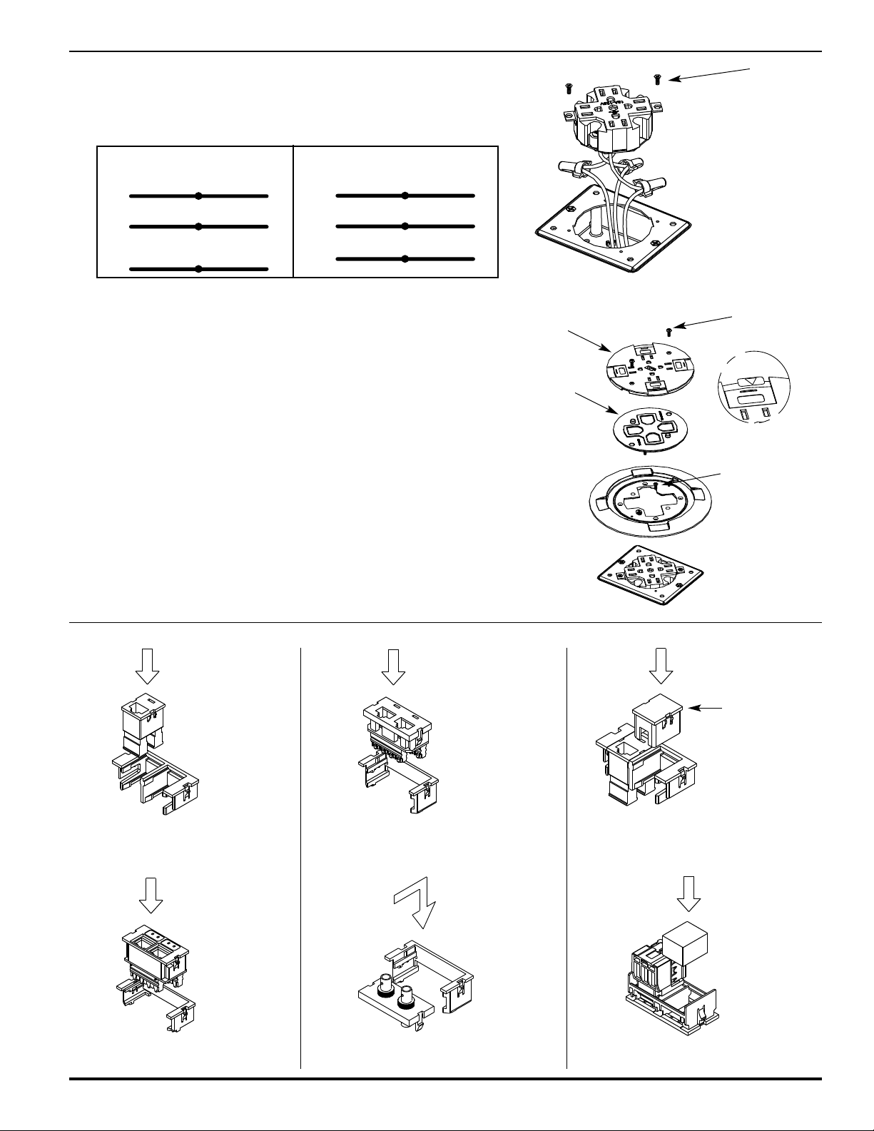
QUAD RECEPTACLE INSTALLATION: (2" [51mm] min. preset depth)
1. Pull conductors through the adapter plate and wire to the receptacle leads.
2. Line up the receptacle strap with the notches in the adapter plate and
secure with (2) #6-32 flat head screws.
ONVENTIONAL WIRING SCHEMATIC ISOLATED GROUND WIRING SCHEMATIC
C
BLACK or HOT BLACK BLACK or HOT BLACK
rom branch circuit from receptacle From branch circuit from receptacle
F
HITE or NEUTRAL WHITE WHITE or NEUTRAL WHITE
W
From branch circuit from receptacle From branch circuit from receptacle
GREEN or GROUND GREEN GREEN or GROUND GREEN
rom branch circuit from receptacle From branch circuit from receptacle
F
ystem Ground
S
#6-32 Flat
Head Screw
CAUTION: Receptacle mounting means not grounded. Grounding
wire connection required. For isolated ground wiring,
connect ground leads to a separate isolated grounding
conductor. See NEC 250-146(d).
QUAD RECEPTACLE COVER:
1. Attach trim flange to cover adapter and receptacle strap using (2)
#6-32 flat head screws.
2. Align gasket over receptacle and press bead into flange.
CAUTION:
Gasket must be in place to provide
scrub water seal.
3. Attach slide cover with (2) #6-32 pan head cover screws.
CAUTION: Do not over tighten cover screws.
4. Apply icon on receptacle slide if wired for isolated ground circuit.
NOTE: Place orange triangle on devices that are wired for
isolated ground. See NEC 250-146 (d).
COMMUNICATION DEVICES:
Point Keystone Tab
Away From Bezel.
Point Keystone Tab
Away From Bezel.
Slide Cover
Gasket
#6-32 Pan
Head Screw
Step 4
#6-32 Flat
Head Screw
TracJack Blank
(supplied)
Ortronics TracJack Bezel and
Communication Jack (TracJack
Modular Inserts sold separately)
Pass & Seymour ACTIVATE
Bezel and Communication Jack
Ortronics Series II Bezel and Communication
Jack (Series II Bezel Included; Series II
Modular Inserts sold separately)
Lower Level Bezel Installation (Typical for Fiber
Installations) (Fiber Jack sold separately)
TracJack
(sold separately)
Communication Jack (sold separately)
Foam Plug
(supplied)

COMMUNICATIONS COVER: (2" [51mm] min. preset depth)
1. Wire and snap appropriate communication jacks into adapters as
shown above.
2. Insert blanking plugs or neoprene foam blocks in unused
communication ports.
3. Insert jacks through underside of trim flange and snap into place.
4. Attach trim flange with jacks to the preset adapter plate using (4)
#6-32 flat head screws.
5. Align gasket over devices and press bead into trim flange channel.
CAUTION: Gasket must be in place to provide scrub water seal.
6. Install slide cover with (2) #6-32 pan head cover screws.
CAUTION: D
o not over tighten cover screws.
PARTITION FEED COVER: (1" [25mm] min. preset depth)
1. Attach conduit flange to the preset adapter plate using (4)
#6-32 pan head screws.
2. Remove screw plugs and install flexible conduit fittings with conduit.
NOTE: Keep screw plugs for future abandonment.
#6-32 Pan
Head Screw
Slide Cover
Gasket
#6-32 Flat
Head Screw
Trim Flange
#6-32 Pan
Head Screw
Conduit
Flange
2" TRADE SIZE PARTITION FEED COVER:
(1" [25mm] min. preset depth)
1. Attach conduit flange to the preset adapter plate using
(4) #6-32 pan head screws.
2. Remove screw plugs and install conduit fittings with conduit.
NOTE: Keep screw plugs for future abandonment.
#6-32 Pan
Head Screw
Conduit
Flange

PRESET INSERT INSTALLATION DETAILS
To Field Installed Presets:
1. Be certain correct preset height is selected.
2. Position preset so that hooks on bottom of preset drop into openings on duct.
3. Push down evenly and slide forward. Knockout tab should snap into opening.
To Remove Mudcap:
1. Strike a 1/4" flat blade screwdriver along the side of the mudcap to deflect the top edge.
2. Use a screwdriver to pry out mudcap.
To Install Alignment Plates:
1. Install plates at first set of presets on each length of duct before securing supports and couplings.
. All presets must be aligned within 1/8" [3.2mm].
2
#2 DUCT SYSTEMS ONLY #4 DUCT SYSTEMS ONLY
S
SYSTEM PRESET CATALOG INCHES
EPTH HEIGHT NUMBER VOLUME
D
2 1/4" [57mm] 7/8" [22.2mm] 419-1 13.7
2 3/4" [70mm] 1 3/8" [34.0mm] 419-11/2 22.6
3 1/4" [83mm] 1 7/8" [47.0mm] 419-2 31.2
3 3/4" [95mm] 2 3/8" [61.0mm] 419-21/2 39.8
4 1/4" [73mm] 2 7/8" [73.0mm] 419-3 48.3
P PRESET CUBIC
Pry Out Here
Galvanized Steel
Screw when Preset
Mudcap
2 1/2" [64mm] 7/8" [22.2mm] 419-1 13.7
3 1/2" [89mm] 1 7/8" [47.0mm] 419-2 31.2
4 1/2" [115mm] 2 7/8" [73.0mm] 419-3 48.3
NOTE: Important!
Tighten Bonding
is activated.
S
SYSTEM PRESET CATALOG INCHES
EPTH HEIGHT NUMBER VOLUME
D
3" [76mm] 1 3/8" [34.0mm] 419-11/2 22.6
4" [102mm] 2 3/8" [61.0mm] 419-21/2 39.8
P PRESET CUBIC
Galvanized Steel
Mudcap
Pry Out Here
1/8" [3.2mm] Concrete over Preset
3.3 Sq. In.
Add 1/4" [6.4mm] to System when
using both #2 and #4 Duct.
Die Cast Preset
(See Chart)
P
1 1/4"
[32mm]
NOTE: Three Duct Systems are Similar.
Alignment Plate
1/8" [3.2mm] Concrete over Preset
S
3.3 Sq. In.
8.5 Sq. In.
1 11/16"
[43mm]
Minimum 1 1/2" [38mm] Concrete
required below duct or solid surface.
Wiremold/Legrand
U.S. and International:
60 Woodlawn Street • West Hartford, CT 06110
1-800-621-0049 • FAX 860-232-2062 • Outside U.S.: 860-233-6251
Canada:
570 Applewood Crescent • Vaughan, Ontario L45K 4B4
1-800-723-5175 • FAX 905-738-9721
Die Cast Preset
(See Chart)
P
S
1 1/2"
[38mm]
© Copyright 2009 Wiremold/Legrand All Rights Reserved
1 002 970T1 0509
 Loading...