

Page 1
®
Walkerduct Pro Series
Wiremold/Legrand electrical systems conform to and should
be properly grounded in compliance with requirements of
the current National Electrical Code or codes administered by
local authorities.
All electrical products may present a possible shock or fire
hazard if improperly installed or used. Wiremold/Legrand
electrical products may bear the mark as UL Listed and/or
lassified and should be installed in conformance with current
C
local and/or the National Electrical Code.
Modular Afterset
I N S T A L L A T I O N I N S T R U C T I O N S
nstallation Instruction No.: 1 000 494 R2 – Updated May 2009
I
Products Covered: 4210, 4215, 4220, 4225, 4230, 4235, and 4240
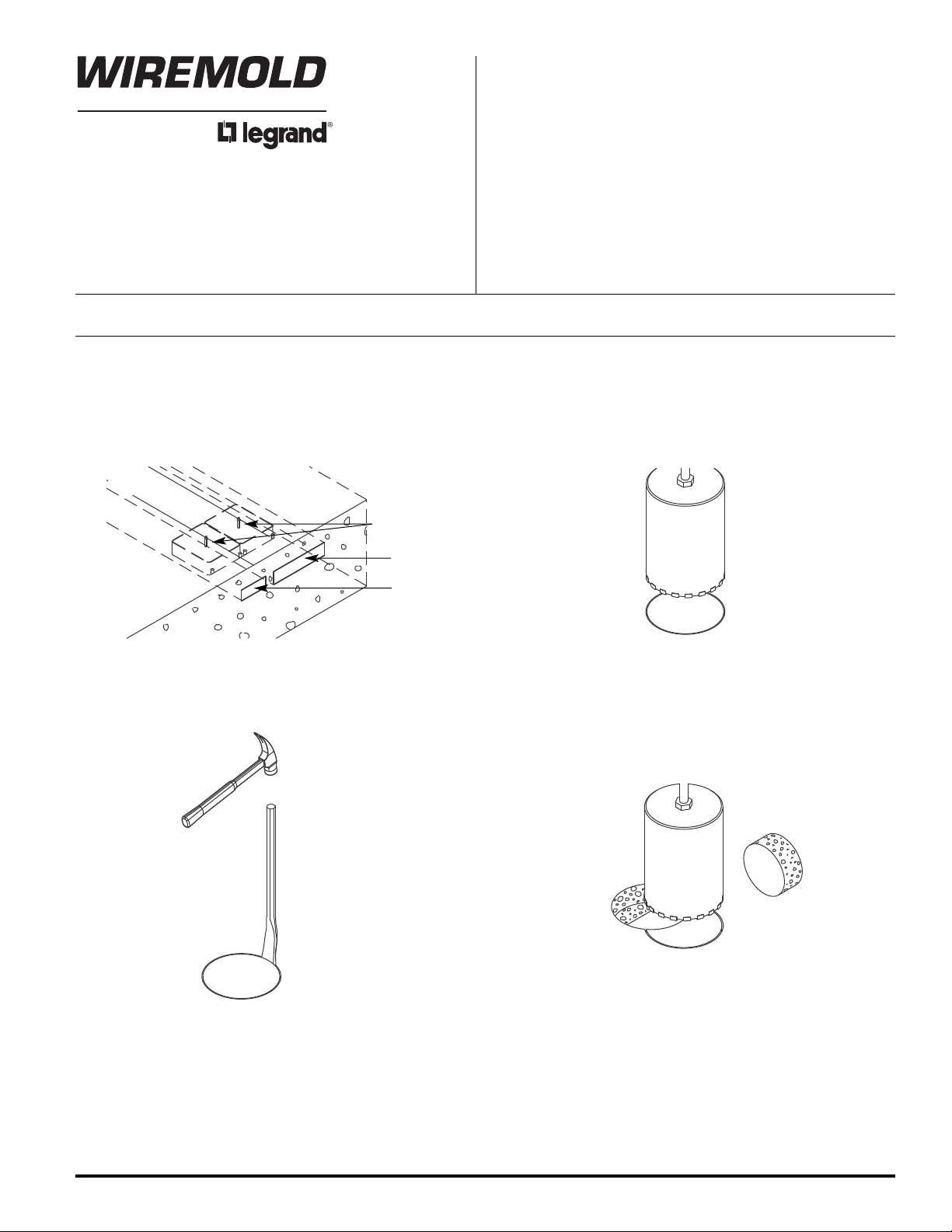
AFTERPOUR INSTALLATION:
Step 1. Locate the center line of the raceway by either
using the markers at the ends of the raceway, or
using two existing fittings in the raceway.
Center Marker
No. 4 Duct
No. 2 Duct
IMPORTANT: Please read all instructions
before beginning.
Step 2. Core drill a 6 1/2" or 7" [165mm or 178mm]
diameter hole in concrete.
CAUTION: Do not cut into the duct.
Step 3. Loosen and remove concrete slug. Step 4. For two- and three-gang: Core drill another 6 1/2" or 7"
[165mm or 178mm] diameter hole over duct keeping
holes at 4 1/8" [105mm] on center. Loosen and remove
slug after coring is complete.
Page 2
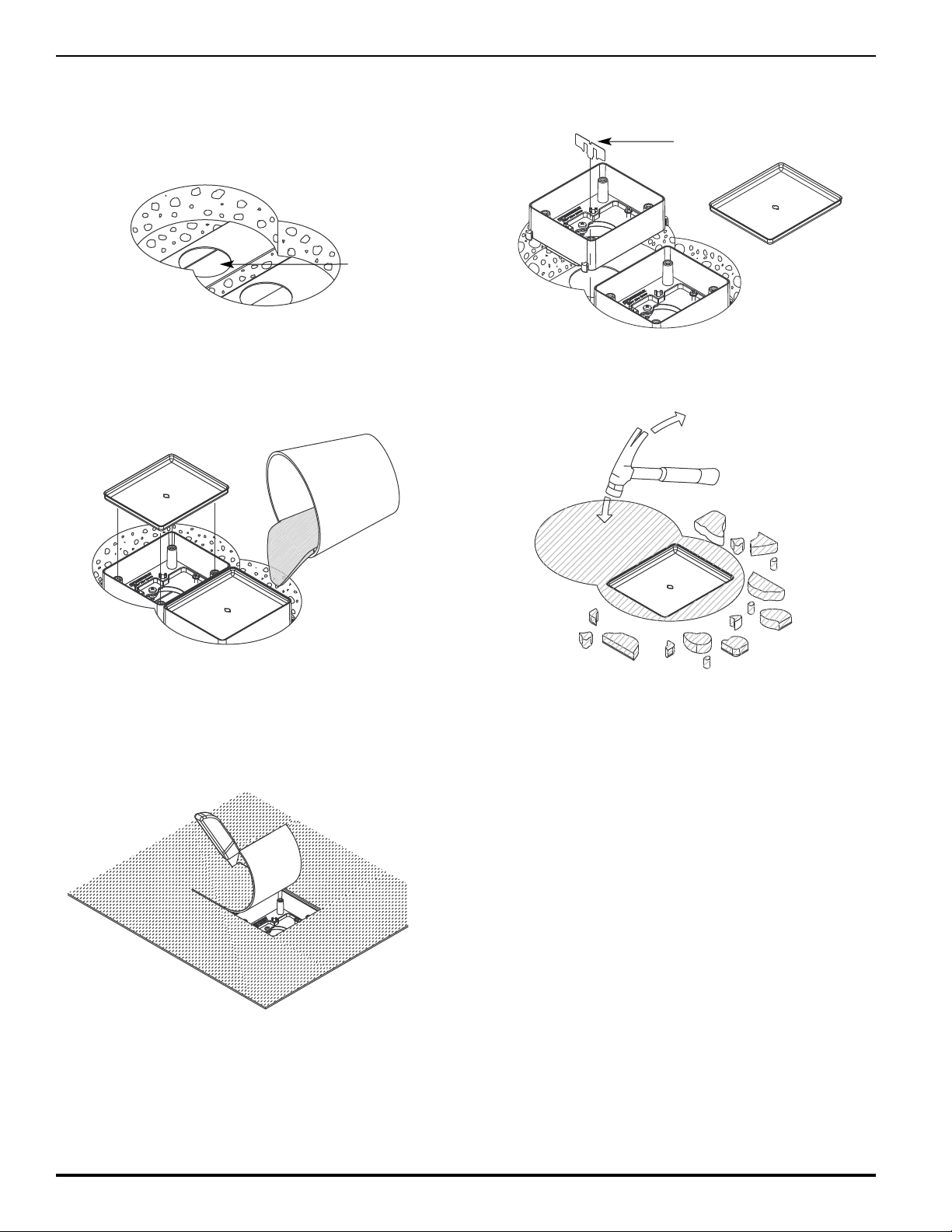
Step 5. Using a 2 1/2" [64mm] diameter hole saw, drill
opening in center of duct. For two- or three-gang,
use template for proper center locations.
NOTE: Holes in No. 4 duct will not be located in
center of duct. Center of holes must be
4 1/8" [105mm] apart.
1/2" [64mm]
2
iameter Hole
D
Step 6. Attach afterset to the duct system by tightening
locking tabs. Secure aftersets together with alignment
clip (two- or three-gang only).
lignment Clip
A
Step 7. Install mudcaps and fill space around afterset and
mudcaps with grout. using trowel, create level,
smooth surface.
Step 9. Remove mudcaps and replace carpet. Using the
afterset as a guide, cut a rectangular opening in the
carpet. Attach desired service fitting.
Step 8. Break out mudcaps after grout has set.
Page 3
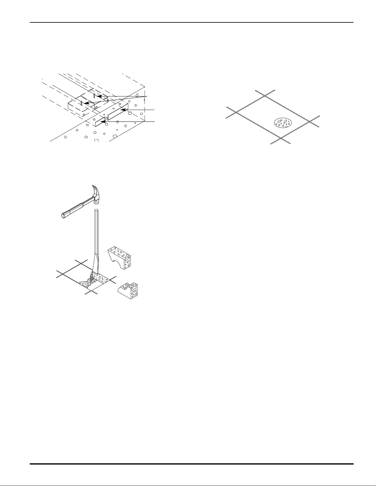
ALTERNATIVE AFTERPOUR INSTALLATION:
Step 1. Locate the center line of the raceway by either
sing the markers at the ends of the raceway, or
u
using two existing fittings in the raceway.
Center Marker
o. 4 Duct
N
No. 2 Duct
Step 3. Loosen and remove concrete slugs.
Step 2. Mark concrete with cutting lines based on single-,
double-, or triple-gang afterset to be installed. Opening
should be approximately 1/2" [12.7mm] wider than the
afterset on all sides. Drill a 2 1/2" [64mm] diameter hole
over the center of the duct to determine depth of
concrete if depth is not known. Set saw to depth of
oncrete and cut opening for the afterset.
c
Step 4. Using a 2 1/2" [64mm] diameter hole saw, drill opening
in center of duct. For two- and three-gang, use template
for proper center locations.
NOTE: Holes in No. 4 duct will not be located in
center of duct. Center of holes must be
4 1/8" [105mm] apart.
Step 5. Complete installation by following Steps 6-9 on page 2.
Page 4

PRE-POUR INSTALLATION:
Step 1. For single preset: Mark a center line down the
iddle of the duct and mark location for preset.
m
For two- or three-gang presets: Locate center of
No. 2 duct for preset using step above and
measure over 4 1/8" [105mm] and mark center for
second preset.
enter Line of
C
fterset/Preset
A
o. 2 Duct
N
No. 4 Duct
Duct Support
Step 3. Place the presets directly over the holes. Connect
the presets together with the alignment clips.
Secure the preset to the duct by tightening the
locking tabs.
Step 2. Drill 2 1/2" [64mm] hole(s) keeping the centers
4 1/8" [105mm] apart.
1/8"
4
105mm]
[
Step 4. Attach the mudcap(s).
2 1/2"
[64mm]
Page 5

PRESET INSERT INSTALLATION DETAILS
To Field Installed Presets:
1. Be certain correct preset height is selected.
2. Position preset so that hooks on bottom of preset drop into openings on duct.
3. Push down evenly and slide forward. Knockout tab should snap into opening.
To Remove Mudcap:
1. Strike a 1/4" flat blade screwdriver along the side of the mudcap to deflect the top edge.
2. Use a screwdriver to pry out mudcap.
To Install Alignment Plates:
1. Install plates at first set of presets on each length of duct before securing supports and couplings.
. All presets must be aligned within 1/8" [3.2mm].
2
#2 DUCT SYSTEMS ONLY #4 DUCT SYSTEMS ONLY
SPPRESET CUBIC
SYSTEM PRESET CATALOG INCHES
EPTH HEIGHT NUMBER VOLUME
D
2 1/4" [57mm] 7/8" [22.2mm] 419-1 13.7
2 3/4" [70mm] 1 3/8" [34.0mm] 419-11/2 22.6
3 1/4" [83mm] 1 7/8" [47.0mm] 419-2 31.2
3 3/4" [95mm] 2 3/8" [61.0mm] 419-21/2 39.8
4 1/4" [73mm] 2 7/8" [73.0mm] 419-3 48.3
Pry Out Here
Galvanized Steel
Mudcap
NOTE: Important!
Tighten Bonding
Screw when Preset
is activated.
SPPRESET CUBIC
SYSTEM PRESET CATALOG INCHES
DEPTH HEIGHT NUMBER VOLUME
2 1/2" [64mm] 7/8" [22.2mm] 419-1 13.7
3" [76mm] 1 3/8" [34.0mm] 419-11/2 22.6
3 1/2" [89mm] 1 7/8" [47.0mm] 419-2 31.2
4" [102mm] 2 3/8" [61.0mm] 419-21/2 39.8
4 1/2" [115mm] 2 7/8" [73.0mm] 419-3 48.3
Galvanized Steel
Mudcap
Pry Out Here
1/8" [3.2mm] Concrete over Preset
3.3 Sq. In.
Add 1/4" [6.4mm] to System when
using both #2 and #4 Duct.
Die Cast Preset
(See Chart)
P
1 1/4"
[32mm]
NOTE: Three Duct Systems are Similar.
Alignment Plate
S
3.3 Sq. In.
Minimum 1 1/2" [38mm] Concrete
required below duct or solid surface.
1/8" [3.2mm] Concrete over Preset
8.5 Sq. In.
1 11/16"
[43mm]
Die Cast Preset
(See Chart)
P
S
1 1/2"
[38mm]
Page 6

Page 7

EMPLATE – Used to locate center of 2 1/2" [64mm] diameter holes cut in duct.
T
NOTE: Holes shown are not 2 1/2" [64mm],
however center locations are correct.
4 1/8"
[105mm]
CAUTION: When printing copies of this
template, please be sure
template is scaled correctly
and is the correct size once
it is printed.
4 1/8"
[105mm]
Page 8

Wiremold/Legrand
U.S. and International:
60 Woodlawn Street • West Hartford, CT 06110
1-800-621-0049 • FAX 860-232-2062 • Outside U.S.: 860-233-6251
Canada:
570 Applewood Crescent • Vaughan, Ontario L4K 4B4
1-800-723-5175 • FAX 905-738-9721
© Copyright 2009 Wiremold/Legrand All Rights Reserved
1 000 494 R2 0509
 Loading...