

LEGRAND Wattstopper LMDM-101 Quick Start Manual
Wattstopper
Blue load
rn ON to last level
Rocker Panel
LMDM-101
LMSW-105
Dimmer
(low voltage, Class 2)
Daylighting
Sensor
®
Digital Lighting Management Low Voltage Dimming Wall Switch (v3)
Gestion numérique de l’éclairage Interrupteur mural basse tension à gradation (v3)
No: 23493 – 10/18 rev. 2
Regulador de pared de bajo voltaje DLM (v3)
Quick Start Guide • Guide de démarrage rapide • Guía de inicio rápido
Catalog Number • Numéro de Catalogue • Número de Catálogo: LMDM-101
Country of Origin: Made in China • Pays d’origine: Fabriqué en Chine • País de origen: Hecho en China
Models ending in -U are BAA and TAA compliant (Product produced in the U.S.)
This unit is pre-set for Plug n’ Go™ operation,
adjustment is optional.
For full operational details, adjustment and more
features of the product, see the DLM System Installation
Guide provided with Wattstopper room controllers, and
also available at www.legrand.us/wattstopper.
Installation shall be in accordance with all applicable
regulations, local and NEC codes. Wire connections
shall be rated suitable for the wire size (lead and building
wiring) employed.
For Class 2 DLM devices and device wiring: To be
connected to a Class 2 power source only. Do not
reclassify and install as Class 1, or Power and Lighting
Wiring.
Do not apply cleaning solvent directly onto unit. Apply
cleaning solvent onto a cloth, then wipe the unit to clean it..
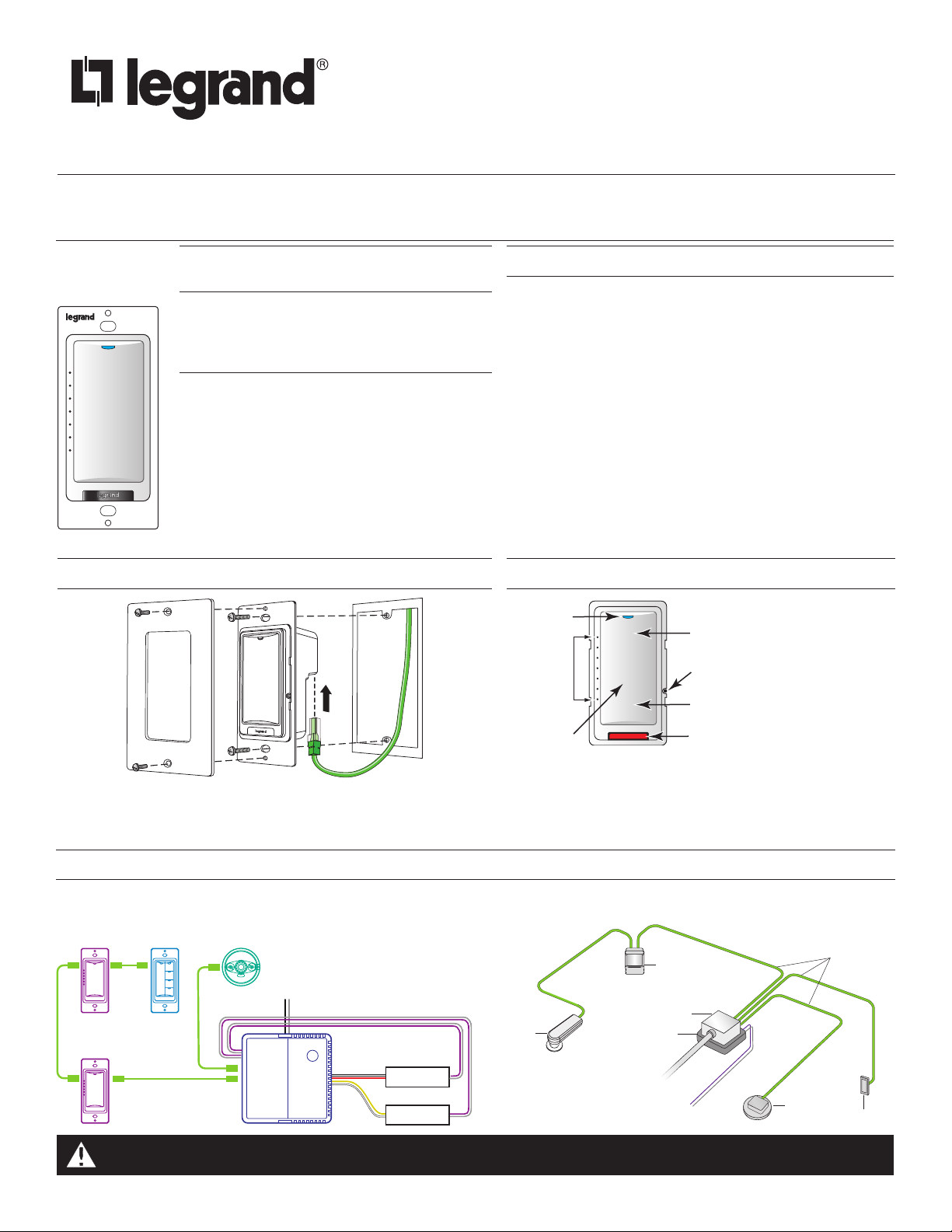
MOUNTING THE SWITCH
WARNING: Do not install to cover a junction box having Class 1, 3 or
Power and Lighting Circuits.
SPECIFICATIONS
Voltage ...................................................................................24VDC
Current Consumption ..................................................................5mA
Power Supply ...................................... Wattstopper Room Controller
Connection to the DLM Local Network ......................... 2 RJ-45 ports
DLM Local Network characteristics when using LMRC-11x/2xx room
controllers:
Low voltage power provided over Cat 5e cable (LMRJ);
max current 800mA. Supports up to 64 load addresses,
48 communicating devices including up to 4 LMRC-10x
series and/or LMPL-101 controllers.
Free topology up to 1,000’ max.
Environment ...................................................... For Indoor Use Only
Operating Temperature ......................32° to 131°F (0° to 55°C)
Storage Temperature ........................23° to 176°F (-5° to 80°C)
Relative Humidity ............................5 to 95% (non condensing)
Patent Pending
BUTTONS AND INDICATORS
status LED
LEDs
show
light
level
setting
When all loads bound to the dimmer are OFF, the Blue load
status LED is dim. A single light level LED is lit to show the last
light level.
When any load bound to the dimmer is ON the load status
LED is bright. The number of illuminated light level LEDs
indicates the highest light level on any of those loads.
Tap when load OFF: Tu
Tap when load ON: Go to full bright
Press & Hold: Ramp Up
Configuration Button
(behind switch plate)
Tap: Fade to OFF
Press & Hold: Ramp Down
Red LED
CONNECTIVITY
The illustrations here show examples of free-topology wiring. The LMDM communicate to all other Digital Lighting Management devices
connected to the low voltage DLM Local Network, regardless of their position on the DLM Local Network.
Dimming Switch
LMDM-101
Dimming Switch
CAUTION: TO CONNECT A COMPUTER TO THE DLM LOCAL NETWORK USE THE LMCI-100. NEVER CONNECT THE DLM
Scene Switch
LMRJ Cables
Occupancy Sensor
Line Voltage
LMRC-212
Dimming
Room
Controller
J-Box
Class 2 0-10 Volt Control Wiring
Line Voltage
0-10 Volt
Ballast
0-10 Volt
Ballast
Corner Mount
Occupancy
Sensor
J Box
LMRC-21x
Room
Controller
To
Load
To 0-10V
Dimming Ballast
LOCAL NETWORK TO AN ETHERNET PORT – IT MAY DAMAGE COMPUTERS AND OTHER CONNECTED EQUIPMENT.
DLM Local Network
LMRJ cables
Ceiling Mount
Occupancy
Sensor
Switch/
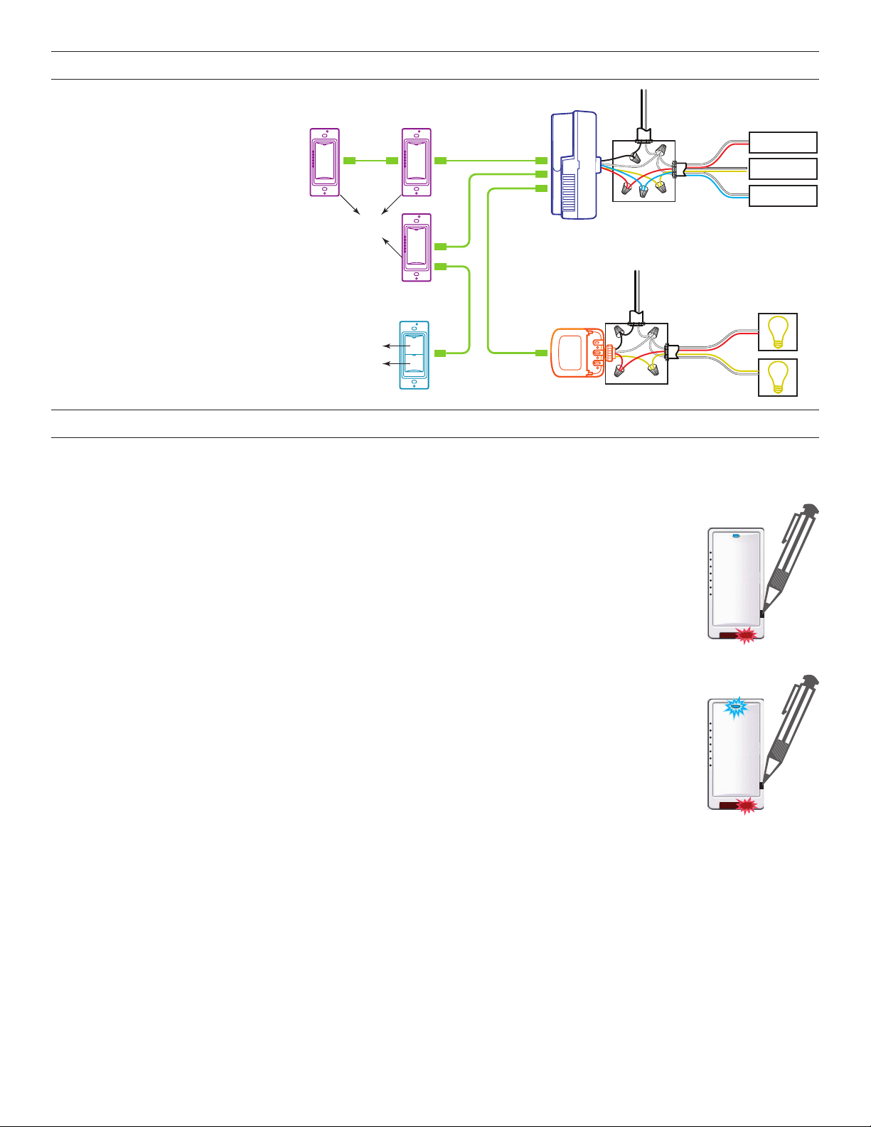
PLUG N’ GO OPERATION (PNG)
Switch
Line Voltage
All loads are automatically bound to the
LMDM-101.
The rocker paddle on the LMDM-101
controls all loads on the DLM Local
Network. Tap the top of the rocker to
turn ON all loads to the last light level.
Tap the bottom to turn OFF all loads.
Dimmable loads dim (ramp down or up)
in response to a press and hold of the
appropriate portion of the rocker paddle.
Switched loads turn OFF when ramped
LMDM-101 LMDM-101
Loads:
1,2,3,4,5
LMRC-213
Line
Voltage
Loads
0-10 Volt
1
2
3
Ballast
0-10 Volt
Ballast
0-10 Volt
Ballast
A
B
C
down below 50% and turn ON when
ramped up above 50%.
To change the loads controlled by the
LMDM-101 see UNIT ADJUSTMENT.
Loads:
2,3,4,5
LMDM-101
LMRC-102
1
Line Voltage
J-Box
Loads
4
A
B
5
UNIT ADJUSTMENT - PUSH N’ LEARN (PNL)
Load Binding Procedure
A configuration button allows access to our patented Push n’ Learn™ technology to change the binding relationship between switch
buttons and loads.
Step 1 Enter Push n’ Learn
1. Using a pointed tool, press and hold the configuration button for 3 seconds, until the Red LED on the switch
begins to blink.
2. When you release the switch’s configuration button, the red LED on other communicating DLM Local
Network devices begins to blink.
3. The DLM Local Network is now in PnL mode. The Red LEDs continue to blink until you exit PnL mode.
4. All loads in the room turn OFF after entering PnL. After one second, one load turns ON. This is Load #1,
which is bound to switch button #1 as part of the Plug n’ Go factory default setting. The Blue LED will be ON
for all devices that are bound to this load.
Step 2 Load selection
1. To step through the loads connected to the DLM Local Network, press and quickly release the configuration
button. The first press turns OFF load 1 and turns ON load 2. The next press turns OFF load 2 and turns
ON load 3, and so forth. As each load turns ON note which devices (switch buttons, sensors, etc.) are
showing the blue LED. These devices are currently bound to the load that is ON.
2. To unbind a switch button or rocker paddle from a load, press the switch button or tap the rocker paddle
while its blue LED is ON. The blue LED turns OFF to indicate the device no longer controls the load that is
currently ON.
3. Pressing the switch button or rocker paddle again while the load is ON rebinds the load to the device and
the blue LED illuminates.
Step 3 Exit Push n’ Learn
1. Press and hold the configuration button until the red LED turns off, approximately 3 seconds.
This device complies with part 15 of the FCC Rules. Operation is subject to the following two conditions: (1)This device may not cause
harmful interference, and (2) this device must accept any interference received, including interference that may cause undesired operation.
NOTE: This equipment has been tested and found to comply with the limits for a Class A digital device, pursuant to part 15 of the FCC Rules.
These limits are designed to provide reasonable protection against harmful interference when the equipment is operated in a commercial
environment. This equipment generates, uses, and can radiate radio frequency energy and, if not installed and used in accordance with the
instruction manual, may cause harmful interference to radio communications. Operation of this equipment in a residential area is likely to
cause harmful interference in which case the user will be required to correct the interference at his own expense.
2

Loads do not operate as expected.
DEL bleue
indiquant
le statut de
la charge
Allume l'appareil au dernier niveau
Les DE
indiquent
le réglage
du niveau
d'éclairage
Panneau de
culbuteur
TROUBLESHOOTING
Rocker paddle LED
doesn’t light
1. Check to see that the the switch is connected to the DLM Local Network.
2. Check for 24VDC input to the switch: Plug in a different DLM device at the switch location. If the
device does not power up, 24VDC is not present.
• Check the high voltage connections to the room controller.
• If high voltage connections are good and high voltage is present, recheck DLM Local Network
connections between the switch and the room controller.
The wrong lights are
controlled
Rocker paddle doesn’t
actuate
LED turns ON and OFF
but load doesn’t switch
1. Configure the rocker paddle to control the desired lights using the Push n’ Learn adjustment
procedure.
1. Make sure the switch frame and button are assembled properly.
2. Make sure that the wall plate is not pinching the frame.
1. Make sure device is not in PnL.
2. Check load connections to room controller.
INSTRUCTIONS EN FRANÇAIS
Cet appareil est préréglé pour un fonctionnement Plug n’ Go™ et
son réglage est optionnel.
Pour connaître tous les détails opérationnels, les réglages et les fonctions
supplémentaires du produit, consulter le guide d'installation du système DLM
fourni avec les Wattstopper contrôleurs de pièce et aussi disponible au
www.legrand.us/wattstopper.
L'installation doit être effectuée conformément à tous les règlements ainsi
qu'aux codes locaux et de la NEC en vigueur. Les raccordements de fils
doivent être classés comme pouvant convenir au calibre du fil (fil de sortie et de
bâtiment) utilisé.
Pour les dispositifs DLM de classe 2 et le câblage du dispositif : Doit être
connecté à une source d'alimentation de classe 2 seulement. Ne pas reclasser
et installer en tant que classe 1 ou en tant que fil d'alimentation ou d'éclairage.
Ne pas appliquer de solvant de nettoyage directement sur l'appareil. Appliquer le
solvant de nettoyage sur un chiffon et frotter l'appareil pour le nettoyer.
SPÉCIFICATIONS
Tension .................................................................................. 24 VCC
Consommation de courant ..........................................................5mA
Alimentation électrique .................... Wattstopper contrôleur de pièce
Connexion au réseau local DLM .................................. 2 ports RJ-45
Caractéristiques du réseau local DLM pendant l'utilisation des
contrôleurs LMRC-11x/2xx:
La basse tension est générée par le câble Cat 5e (LMRJ);
courant maximal 800mA. Supporte jusqu'à 64 adresses de
charge, 48 dispositifs de communication incluant jusqu'à 4
séries LMRC-10x et contrôleurs LMPL-101. Topologie libre
allant jusqu'à 305 m (1 000 pi) max.
Environnement .................................Pour usage intérieur seulement
Température de fonctionnement ........ 0 ° à 55°C (32 ° à 131°F)
Température d'entreposage ............-5 ° à 80 °C (23 ° à 176 °F)
Humidité relative ..............................5 à 95 % (non condensée)
Brevet en instance
MONTAGE DE L'INTERRUPTEUR
MISE EN GARDE: Ne pas installer avec une boîte de
jonction dotée de circuits de classe 1, 3, d'alimentation
ou d'éclairage.
BOUTONS ET INDICATEURS
Appuyer quand la charge est éteinte:
L
Lorsque toutes les charges liées au gradateur sont éteintes, la DEL bleue
indiquant le statut de la charge est faible. Une DEL de niveau d'éclairage
unique s'allume pour indiquer le denier niveau d'éclairage.
Lorsque toute charge liée au gradateur est allumée, la DEL indiquant le
statut de la charge est vive. Le nombre de DEL de niveau d'éclairage
allumée indique le niveau d'éclairage le plus élevé pour chacune de ces
charges.
3
Appuyer lorsque la charge est allumée: Atteint le niveau le plus fort
Presser et tenir : Augmentation
Bouton de configuration
(derrière la plaque de commutation)
Appuyer : Diminue jusqu'à l'extinction
Appuyer et tenir : Diminution
DEL rouge
 Loading...