

LEGRAND Wattstopper LMCP-GE24, Wattstopper LMCP-GE48 Installation Instructions Manual

Wattstopper
Mounting plate
LMRD-12-M
P/N # 841436
Mounting plate screw location
(Total 12 #4-40 screws fo
mounting plate)
Power supply connection detail
®
DLM - DLM GE SWS or TLC Relay to LMCP Retrofit Kits
No: 24813 – 11/16 rev. 1
Installation Instructions • Instructions d’Installation • Instrucciones de Instalación
Catalog Numbers • Les Numéros de Catalogue • Números de Catálogo: LMCP-GE24/LMCP-GE48
Country of Origin: Made in China • Pays d’origine: Fabriqué en Chine • País de origen: Hecho en China
LMCP-GE24 RETROFIT KIT INSTALLATION
Step 1: Remove all interior components
leaving relays and power supply only.
Fig. 1: Example GE24
panel assembly
Fig. 2: After removing
interior items
Step 4: Install LMRD and LMPI cards.
CAUTION: Do not overtighten screws.
Step 2: Remove LMRD cards
from adapter plate.
Fig. 3: Remove LMRD
Step 3: Install LMRD adapter plate.
screw locations
(Total 4 #6-32
screws for
mounting plate)
P
Fig. 4: Install LMRD adapter plate
Step 5:
• Connect LMRD card to LMPI.
• Connect relays to LMRD card.
• Connect power to LMPI.
(See Relay Connection Details for DIP Switch settings.)
LMRD-12
s
r
P/N # 16694
Mounting plate screw locations
(Total 4 #6-32 screws for
mounting plate)
Fig. 5: LMRD and LMPI mounting details
LMPI-ASSY
P/N # 770431
Step 6: Apply upgrade label.
Fig. 6: Connection details
Fig. 7: Label location suggestion
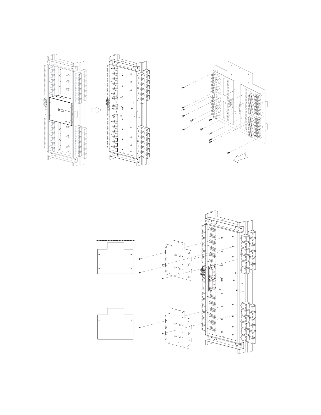
LMCP-GE48 RETROFIT KIT INSTALLATION
Mounting plate
screw locations
(Total 4 #6-32
screws for
mounting plate)
NOTE: Only two (2)
screws needed for
bottom plate)
Step 1: Remove all interior components,
leaving relays and power supply only.
Fig. 8: Example GE48
panel ssembly
interior items
Step 2: Remove LMRD cards from adapter plate.
Fig. 10: Remove LMRDFig. 9: After removing
Step 3: Install adapter plate.
LMRD-12-MP
P/N # 841436
LMRD-12-MP
P/N # 841436
Fig. 11: Adapter plate mounting detail
2
 Loading...