

LEGRAND Wattstopper InteliSwitch TS-400 Installation Instructions Manual
Wattstopper
®
InteliSwitch® Digital Time Switch – 120/277VAC
No: 24164 – 09/16 rev. 1
Installation Instructions • Instructions d’Installation • Instrucciones de Instalación
Catalog Number • Numéro de Catalogue • Número de Catálogo: TS-400
Country of Origin: Made in China • Pays d’origine: Fabriqué en Chine • País de origen: Hecho en China
SPECIFICATIONS
Voltages ............................................................ 120/277VAC, 50/60Hz
Load Requirements
@ 20VAC .......................... 0-800W ballast, LED or Incandescent
@ 277VAC .............................................. 01200W ballast or LED
@ 125VAC ..........................................................................1/6 hp
Time-Out Adjustment ............................................... 5 min. to 12 hours
Time-Out Override .......................5 min. to 1 hour in 5 min. increments
..................................... 1 hour to 12 hours in 15 min. increments
Operating Temperature .................................32° to 104°F (0° to 40°C)
Humidity ............................................. Rh 5% to 95%, non-condensing
U.S. Patent: 5,540,113
5,804,991
DESCRIPTION AND OPERATION
The InteliSwitch® TS-400 is a digital time switch that automatically turns lights off after a preset amount of time. The lights can also
be turned off anytime during the timer’s countdown by pushing the ON/OFF button. The TS-400 has four adjustable features: time-out
period, time scroll direction, time-out visual, and audible warnings.
Time-Out Period
The timer can be adjusted to hold lights on for five minutes to 12 hours. The default setting is 3 hours.
See the DELAY switch adjustment to set the length of the time-out period.
Time Scrolling
The user can manually and temporarily override the time-out period without changing the DELAY
adjustment. The SCROLL adjustment determines whether the user’s override options decrease from a
longer time to a shorter time (scroll down) or increase from a shorter time to a longer time (scroll up).
To choose the scrolling direction, consider the time-out DELAY setting, and then whether the usual
temporary need will be for more or less time.
Override Operation
Holding the ON/OFF button for longer than 4 seconds causes the timer to scroll through time
increments, starting from the time-out DELAY setting. Releasing the ON/OFF switch resumes the
countdown from that point. The minimum override setting is 5 minutes, maximum 12 hours.
The timer resets automatically to the time-out DELAY setting when the countdown runs out or the
ON/OFF button is pushed.
Visual (Flash) Option
If this option is on there are two occasions when the controlled lights flash. They flash one time
when the countdown reaches 5 minutes and twice when the countdown reaches 1 minute.
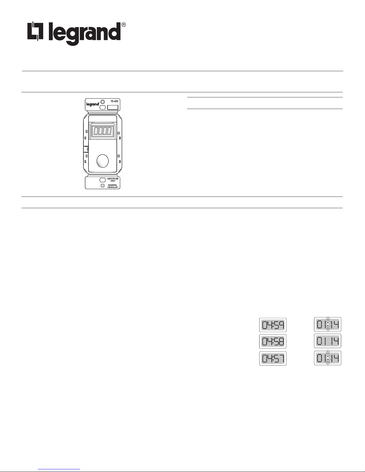
Timer Countdown
Since the time-out period can be
set for 5 minutes to 12 hours, the
time is displayed in two different
ways. For a countdown of less
than an hour, the display shows
minutes:seconds. The seconds
count down. For a countdown of
more than an hour, the display
shows hours:minutes, the colon
flashes every second.
Minute
Countdown
Seconds
Elapsed
:01
:02
:03
Countdown
Hour
Audible (Sound) Option
If this option is on, the timer beeps every 5 seconds during the last minute of the time-out period.
+RW
1HXWUDO
wire wrap
Strip Gauge
12.7mm
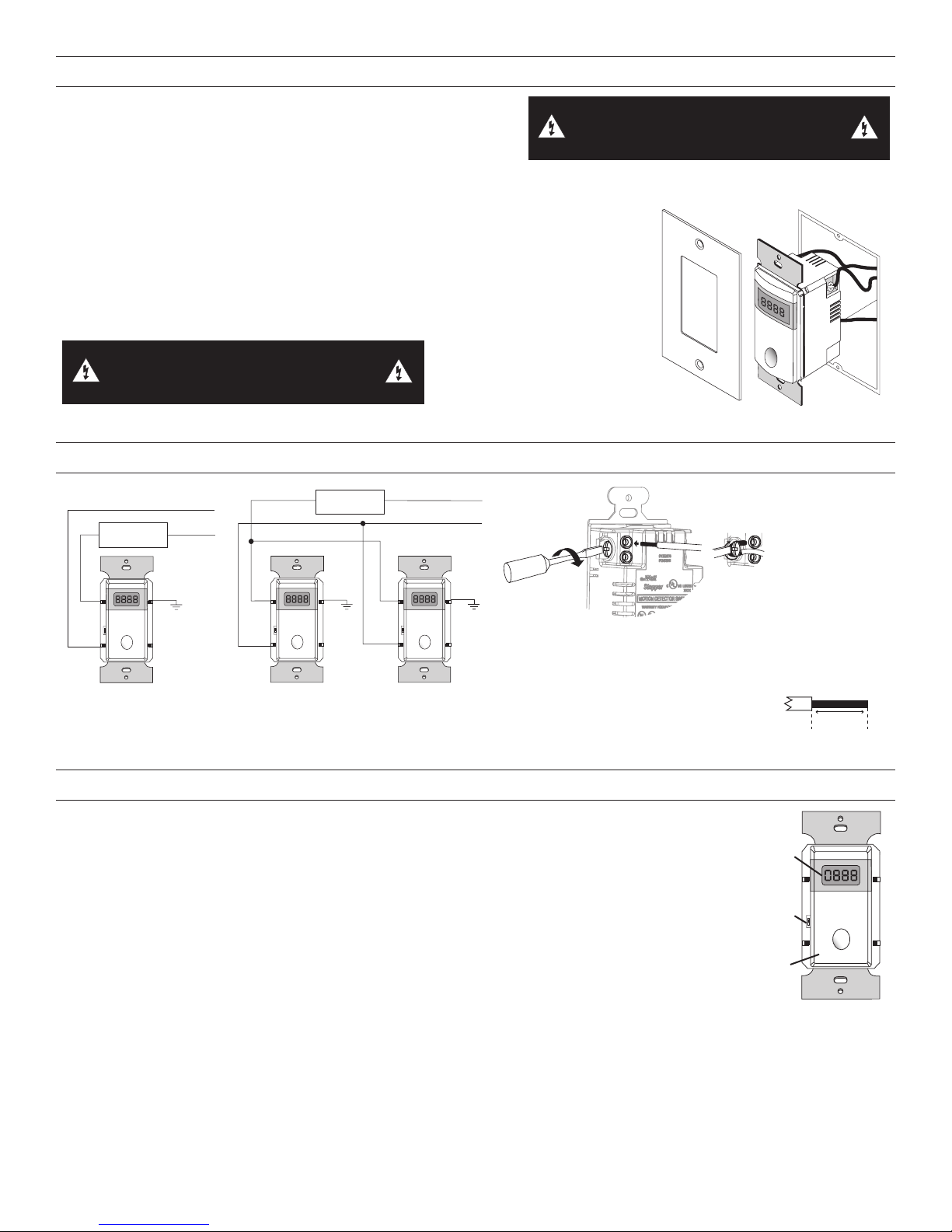
INSTALLATION
1. Connect the existing wires to the switch terminals.
• Hot to Line;
• Load to Load;
WARNING: TURN THE POWER OFF AT THE
CIRCUIT BREAKER BEFORE WIRING.
• Ground to Ground.
2. Attach the time switch to the wall by mounting it in the wall box with 2 mounting screws provided.
3. Turn on power to the time switch
4. 7-15 seconds after power is supplied to the time switch, it will be ready to function.
The time switch beeps and the word OFF appears in the display. Push the ON/
OFF switch to activate the lights. The timer begins its countdown. Push the ON/OFF
switch during countdown to turn the lights off.
5. Select feature settings using the Switch Adjustment procedures.
6. Install cover plate.
WARNING: BE SURE THE GROUND
WIRE IS SECURELY CONNECTED.
WIRING
/RDG
21
/RDG
1HXWUDO
*URXQG
/RDG
21
/RDG
*URXQG
/RDG
21
+RW
*URXQG
Wire insert
Insert or wrap wire as shown and
tighten screw in the clockwise direction.
/LQH
/LQH
/LQH
Single-switch Wiring Three-way Wiring
When using a three-way application,
lights may be turned on from either
switch, but can only be turned off at
the switch that turned them on.
SWITCH ADJUSTMENT
Enter Settings Mode by pressing the Calibration Button (located on the left, behind the faceplate).
• If no input occurs within four seconds the display flashes then moves to the next setting.
• Press the Calibration Button to view the settings without making changes.
• Press the ON/OFF button within four seconds to change the setting.
DELAY: 5 min. to 12 hr.
DELAY sets the time-out period. The selections begin at the currently set time (3 hours, default). When
the time is less than an hour, the time increases by 5 minutes each time you press the ON/OFF button.
When the time is more than an hour, it increases by 15 minues. When the selection passes 12 hours, it
restarts the selection scrolling at 5 minutes.
SCROLL: Up or Down (dn)
To have the user’s time override options decrease from a longer time to a shorter time, set Scroll for dn
(down). To increase from a shorter time to a longer time, set Scroll for UP.
FLASH: ON or OFF
Optional
LCD
Display
Calibration
Button
ON/OFF
Button
#12 – #14 AWG
1/2"
Cu Wire Only
ON
1
TS-400
SOUND: ON or OFF
When the setting selection is complete the unit will either:
• Beep once and display END if the calibration button is being held; release the button to continue.
• Beep three times while it displays END. This gives you a chance to press the ON/OFF button to restart the setting procedure.
If you don’t press either button within three seconds, the unit exits the Settings Mode and resumes its previous state.
2
 Loading...