

LEGRAND Wattstopper HB330W, Wattstopper HB340W, Wattstopper HB350W Installation Instructions Manual
Wattstopper
Sensor Assembly
®
High Bay • Line Voltage • Passive Infrared
IP65 Occupancy Sensors for Wet Locations
No: 24140 – 08/17 rev. 2
Installation Instructions • Instructions d’Installation • Instrucciones de Instalación
Catalog Numbers • Les Numéros de Catalogue • Los Números de Catálogo: HB330W, HB340W, HB350W
Country of Origin: Made in China • Pays d’origine: Fabriqué en Chine • País de origen: Hecho en China
SPECIFICATIONS
HB350W Voltages ..............................................................Voltages120/277VAC,60Hz
Load Requirements
@120VAC, 60Hz ........................................................0-800W ballast or tungsten
@277VAC, 60Hz .........................................................................0-1200W ballast
@120VAC ...................................................................................................1/6 hp
HB340W Voltages .......................................................................... 347/480VAC, 60Hz
Load requirements ...................................................................... 0-1200W ballast
HB330W Voltages .......................................................................... 208/240VAC, 60Hz
HB3x0W L2W/
HB3x0W L3W
HB3x0W L7W
Load requirements ...................................................................... 0-1200W ballast
Wiring cable ....................................3 or 4-conductor 18AWG stranded, UL Style 2517
Unit Dimensions .................................................................. 4.08” diameter, 1.88” thick
Threaded nipple ........0.81” diameter, 0.40” long fits standard 1/2” electrical conduit fitting
Weight ............................................................................................0.28 lb (130 grams)
Material .........................................................ABS, UL94-5VA flame retardant material,
................. UV resistant, indoor use only, minimum plastic wall thickness 2.5mm
Environment ......................................................................................... IP65 Compliant
Operating temperature ................................................. -40°F (-40°C) to 131° F (55°C)
Storage temperature ..................................................... -40°F (-40°C) to 176°F (80°C)
Operating humidity ........................................................ 5 to 95% RH, non-condensing
Maximum Dew Point .................................................................................29°C (85°F)
US Patents: ........................................................................... 5,640,113 and 5,804,991
DESCRIPTION AND OPERATION
The HB3x0W occupancy sensors are designed for automatic lighting control in high bay wet location applications. The HB3x0W sensors
contain a passive infrared sensor (PIR). The sensors are modular and are made up of two parts, a Sensor Module (HB3x0W) and a
Lens (HBLxW).
The sensor module is available in three models for different line voltage applications: HB350W for 120/277VAC, HB340W for
347/480VAC, and HB330W for 208/240VAC.
The sensors use a set of DIP switches to set the time delay and PIR sensitivity as explained on page 3. The HB350W provides a single
load controlling relay. The HB330W and HB340W have two relays for phase switching.
INSTALLATION OVERVIEW
1. Review the ADJUSTMENTS section and complete any
necessary DIP switch setting changes.
2. Mount the sensor so the lens is below the edge of the fixture
and away from the lamps. Heat from the lamps could affect
CIRCUIT BREAKER BEFORE INSTALLING THE SENSOR.
the sensor operation.
Make sure that you have the appropriate accessories for the sensor mounting
configuration. (See Mounting Options.)
3. Assemble any necessary mounting accessories and attach them to the sensor
module. Make sure that the flying leads from the sensor module cable are
accessible inside the fixture.
4. Connect the line voltage and load wires to the sensor leads as shown in the
applicable Wiring Diagram for the sensor module.
• Do not allow bare wire to show.
• Make sure all connections are secure.
• Check all gaskets for watertight fit.
5. Check sensor operation. Refer to the TESTING section.
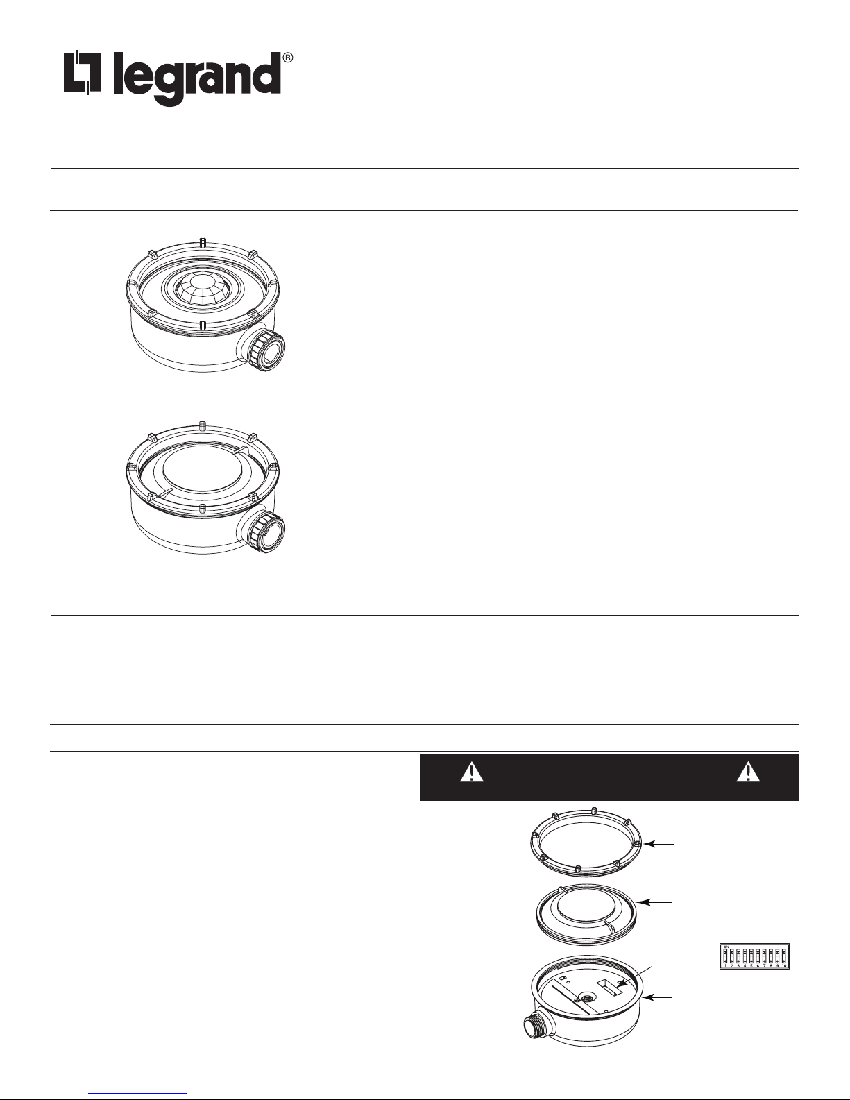
6. Attach the Lens to the HB3x0W as shown in the sensor assembly drawing.
TURN THE POWER OFF AT THE
CAUTION
Tightening ring
HBLxW (lens module)
L7 lens may require pliers
to remove the lens. (Grab
one of the fins to remove.)
DIP switches
HB3x0W (sensor module)

ADJUSTMENTS
connector (supplied by others)
MOUNTING OPTIONS
The sensor is pre-set at the factory to meet the requirements of most
applications. Review this section if your application requires changing
factory pre-sets.
Sensor factory pre-sets are as follows (default settings are bold):
Factory Switch Settings (N/A = not applicable, no effect)
1 2 3 4 5 6 7 8 9 10
ON OFF OFF OFF OFF ON ON OFF N/A N/A
PIR Sensitivity (switches 1&2) .....................Normal
Time Delay (switches 3-7) ....................15 minutes
Override (switch 8) ....Occupancy control enabled
PIR Sensitivity (Switches 1-2)
The factory setting (Normal) is suitable for most applications, but
it may be necessary to adjust the PIR sensitivity if there is any
environmental interference causing false triggers or if sensitivity
needs to be increased for your particular application. Use DIP
switches 1 & 2 to adjust sensitivity.
Switch 1 2 PIR SENSITIVITY
OFF OFF High
ON OFF NORMAL
OFF ON Medium
ON ON Low
Time Delay (Switches 3-7)
Use DIP switches 3 to 7 to adjust the time delay.
As shown in the illustration, the HB3x0W can be attached
directly to a watertight fixture or junction box that is equipped
with a threaded nipple. The center of the threaded nipple should
be no more than approximately one inch (1”) from the bottom of
the fixture to avoid blocking the sensor’s view.
Wet location
light fixture
(supplied by
others)
HB3x0W
sensor
Threaded female
HB3x0W attached to a watertight light xture
1
/2”
The HBEM3W extender module allows attaching the sensor to
the side of the fixture so that the lens can be positioned below
the bottom edge of the fixture. The wiring cable is threaded
through it and into the fixture for connection. The two sides of
the HBEM3W snap together to protect the cable.
The extender housing is not watertight, but the inner flange rings
on the chase nipple and the HB3x0W housing fit into grooved
rubber rings on the the cable. This keeps moisture from entering
the fixture and sensor at those locations.
Switch 3 4 5 6 7 TIME DELAY
ON ON ON ON ON 15 seconds
OFF ON ON ON ON 5 minutes
OFF OFF ON ON ON 10 minutes
OFF OFF OFF ON ON 15 minutes
OFF OFF OFF OFF ON 20 minutes
OFF OFF OFF OFF OFF 30 minutes
Override (Switch 8)
The override disables the occupancy control feature of the HB3x0W
sensor module. When occupancy control is disabled, the load
remains ON as long as the sensor is powered.
Switch 8 Load Effect
OFF Controlled by Occupancy
ON PIR override. Load always ON
Threaded nut
Wet location
light fixture
(supplied by others)
Rubber washer
Chase nipple
HBEM3W
Extender
housing
HB3xxW sensor
HB3x0W attached to a watertight light xture using HBEM3W
2
 Loading...