

LEGRAND Wattstopper FSP-211B, Wattstopper FSP-211B-S, Wattstopper FSP-211B-D Installation Instructions Manual
Wattstopper
r
PIR Sensor
®
High/Low/Off, PIR Fixture Integrated Outdoor Sensor In IP66 Enclosure
Haut/Bas/Éteint,
Luminaire avec capteur IRP extérieur intégré dans un boitier IP66
No: 22834 – 05/17 rev. 4
Alto/Bajo/Apagado, Sensor exterior integrado del aplique PIR en gabinete IP66
Installation Instructions • Instructions d’Installation • Instrucciones de Instalación
Catalog Numbers • Les Numéros de Catalogue • Números de Catálogo: FSP-211B, FSP-211B-S, FSP-211B-D
Country of Origin: Made in China • Pays d’origine: Fabriqué en Chine • País de origen: Hecho en China
SPECIFICATIONS
Voltage .............................................120V/277V, 50/60Hz
.............................230-240V, 50/60Hz, Single Phase
Load Ratings
@230-240V ............. 0 – 300W Ballast or LED Driver
@ 120V ....0-800W Tungsten, Ballasts or LED Driver
@ 277V ................. 0 – 1200W Ballast or LED Driver
Motor @ 120V/277V........................................1/6 HP
Wiring .................................................................... 18AWG
Length .......36” (91.44cm), 30” (76.2cm) from nipple
Line Voltage ................................Line, Neutral, Load
Low Voltage .....................Dim + (violet), Dim - (gray)
Operating Temperature ......-40°F (-40°C) to 167°F (75°C)
Tightening Skirt/Nut Torque ..........................25 – 30 in-lbs
Dimensions
Collar .................................. 1.30” diameter (33.0mm)
Collar height ...................................... 0.64” (16.3mm)
Body .. 5.7”L x 2.3”W x 3.5”H (145mm x 60mm x 90mm)
Weight ........................................................... 2.8 oz (80 g)
Enclosure ............................................. IP66 (NEMA STD)
Coverage
FSP-L2 Lens @ 8’ height ..............up to 44’ diameter
FSP-L3 Lens @ 20’ height ............up to 40’ diameter
FSP-L7 Lens @ 40’ height ..........up to 100’ diameter
DESCRIPTION AND OPERATION
Adjustments and Features
High Mode ..................................................0 V –10 V
Low Mode ................................. . . . . 0 V – 9.8 V, Off
Time Delay .................... 30 seconds, 1 min – 30 min
Cut Off ............... Disable, 1 min – 59 min ,1 hr – 5 hr
Sensitivity .................On-Fix, Off-Fix, Low, Med, Max
Hold Off Setpoint ................Auto, None, 1 fc – 250 fc
Ramp Up .............................. Disable, 1 sec – 60 sec
Fade Down ........................... Disable, 1 sec – 60 sec
Photocell Setpoint for On/Off .....................1 – 250 fc
Factory Defaults
High Mode .......................................................... 10 V
Low Mode ................................................... . . . . 1 V
Time Delay ........................................................5 min
Cut Off ................................................................. 1 hr
Sensitivity ...........................................................Max
Hold Off Setpoint ...........................................Disable
Ramp Up ........................................................Disable
Fade Down .....................................................Disable
Photocell Setpoint for On/Off .........................Disable
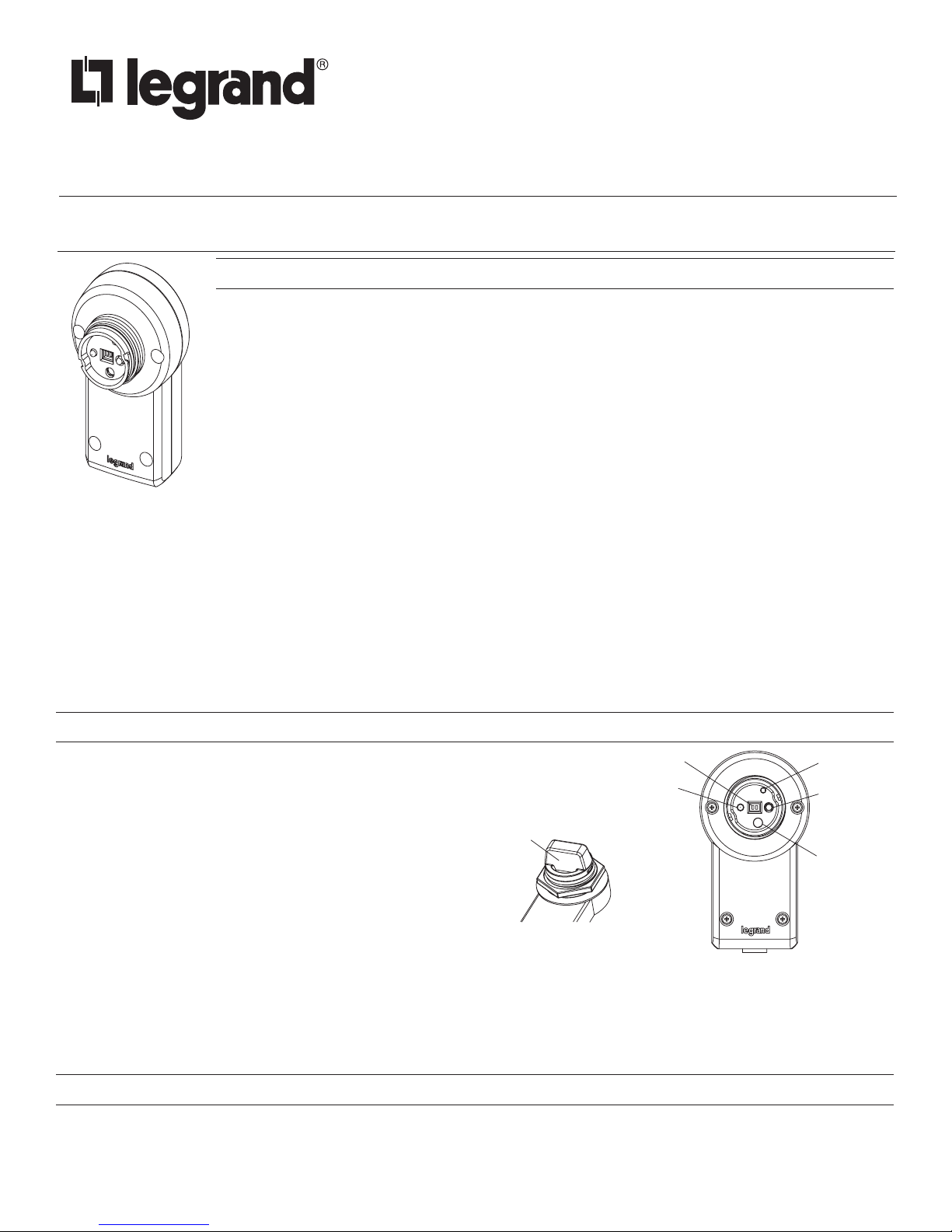
The FSP-211B is an IP66 rated motion sensor that dims lighting from
high to low based on movement.
Three configurations are available. The FSP-211B mounts inside the
fixture and the PIR lens connects to the FSP-211B through a 1.30”
diameter hole in the bottom of the fixture. The FSP-211B-S mounts to
a fixture/enclosure with a 1/2” knock out, via a nipple on the back. The
FSP-211B-D has a drop mount nipple, for mounting on to a pole, or to
Motion Indicator
Red LED
Sensor Protection Cap
Light Sensor
IR Transmitte
IR Receiver
a fixture.
The sensor uses passive infrared (PIR) sensing technology that reacts to
changes in infrared energy (moving body heat) within the coverage area.
Once the sensor stops detecting movement and the time delay elapses,
lights will go from high to low mode and eventually to an OFF position if
it is desired. Sensors must directly “see” motion of a person or moving
NOTE: Remove Cap before use
object to detect them, so careful consideration must be given to sensor
luminaire placement and lens selection. Avoid placing the sensor where obstructions may block the sensor’s line of sight.
The FSP-211B operates single phase at 120V/230V/240V/277V. No power pack is required. It is designed to be installed in indoor and
outdoor environments.
NOTE: When the FSP-211B is powered up the first time, it will use factory default parameters to operate. If adjustments are needed,
the FSIR-100 configuration tool must be used.
LENS OPTIONS
Several lenses are available for use with the FSP-211B. Lenses give coverage at mounting heights between 8’ - 40’ for applications
such as, offices, warehouses and outdoor use. Density and range of the coverage is determined by the type of lens and mounting
height. Lens modules are IP-66 rated when combined with an FSP-211B sensor mounted to an outdoor rated fixture. See the FSP-Lx
Coverage Guide for more information.

Mounting Within Fixture
12
INSTALLATION
There are three configurations of the sensor:
• The FSP-211B mounts inside the fixture.
• The FSP-211B-S mounts to a fixture or an enclosure with a 1/2”
TURN THE POWER OFF AT THE CIRCUIT BREAKER
knockout.
• The FSP-211B-D mounts to a pole or fixture.
Mounting Inside the Fixture
1. Determine an appropriate mounting location inside the light fixture
minimizing the electric light contribution to the sensor’s photocell.
Allow a minimum distance of 0.2” (5.1mm) from the wiring end of
the sensor to the wall of the fixture.
Inside Fixture
Wall
2. Drill a hole 1.30” (33.0mm) in diameter through the sheet metal in
the bottom of the fixture.
3. Add the rubber gasket to the threaded collar, and install the
sensor face down, parallel to the mounting surface. Ensure the
rubber gasket touches the inside surface of the fixture. Install
the skirt securely against the fixture to a torque of 25-30 in-lbs to
ensure IP rating is maintained.
Mounting to a Fixture/Enclosure – Straight Nipple
NOTE: The Outside Fixture Wall thickness should be no
1. Determine an appropriate mounting location minimizing the
electric light contribution to the sensor’s photocell.
2. If there is no knockout, drill a hole 0.875” (22mm) in diameter through the sheet
metal in the fixture or enclosure.
3. Add the rubber gasket to the nipple, and install the sensor face down. Ensure the
rubber gasket touches the surface of the fixture. Install the nipple nut securely
against the fixture to a torque of 25-30 in-lbs to ensure IP rating is maintained.
Mounting to a Pole or Fixture – Drop Nipple
1. Determine an appropriate mounting location on the pole.
2. Drill a hole 0.875” (22mm) in diameter through the pole.
3. Add the rubber gasket to the nipple, and install the sensor face down. Ensure the
rubber gasket touches the surface of the fixture. If needed, add the nut between the
sensor body and the rubber gasket to ensure a secure fit. Install the nipple nut securely
against the fixture to a torque of 25-30 in-lbs to ensure IP rating is maintained.
WARNING
BEFORE INSTALLING THE SENSOR.
Rubber
Gasket
Skirt
Outside
Fixture Wall
Skirt
Lens Assembly
Rubber
Gasket
greater than 0.125” (3.18mm) for optimal sensor
mounting and security.
Straight Nipple Mount
Nipple
Rubber
Gaskets
Drop Nipple Mount
Fixture
Wall
Nipple
Nut
Completing the Installation
1. Align the locking features between the sensor and lens module and push the lens
module forward until the o-ring seals firmly. Turn the lens module clockwise to
ensure it locks in place.
2. Connect wires as shown in wiring diagram.
3. Restore power from the circuit breaker.
NOTE: The IP66 rating for this unit is based on proper installation as indicated above.
However, as Fixture housings may vary in thickness, material, and hole dimensions
to accommodate this unit, all precautions to maintain IP66 should be considered
with the combination and installation of the unit to the Fixture Housing. This includes
installation to an IP66 rated Fixture Housing and use of suitable outdoor rated
silicone seals or accessories.
WIRING
Load
(Red)
Line (Black)
Neutral
(White)
Neutral
Non-Dimming
Load
Violet
Gray
Dim (+)
Violet
Dim (-)
Gray
Dimming
Load
Drop Nipple Mount
Nut
Nipple
Rubber
Gaskets
Load
(Red)
Line (Black)
Nipple
Rubber
Gaskets
Neutral
(White)
Neutral
Nipple
Nut
Nipple
Nut
2
FSP-211B CONFIGURATION
* Distance may vary depending on the lighting environment
Select
Right/Next
IR tx/rx
The configuration process establishes the appropriate parameters for the FSP-211B operation. This is done through the FSIR-100
configuration tool. If no configuration steps are taken, the sensor will use its default parameter values.
USING THE FSIR-100 CONFIGURATION TOOL
The FSIR-100 Wireless IR Configuration Tool is a handheld tool for changing defaults and testing of WattStopper FSP-211B. It provides
wireless access to the FSP-211B sensors for parameter changes and testing.
The FSIR-100 display shows menus and prompts to lead you through each process. The navigation pad provides a simple way to
navigate through the customization fields.
Within a certain mounting height of the sensor, the FSIR-100 allows modification of the system without requiring ladders or tools; simply
with a touch of a few buttons.
The FSIR-100 IR transceiver allows bi-directional communication between the FSP-211B and the FSIR-100 configuration tool . Simple
menu screens let you see the current status of the sensor and make changes. It can change FSP-211B sensor parameters such as
high/low mode, sensitivity, time delay, cut off and more. With the FSIR-100 you can also establish and store FSP-211B parameter
profiles.
BATTERIES
The FSIR-100 operates on three standard 1.5V AAA Alkaline batteries or three rechargeable AAA NiMH
batteries. The battery status displays in the upper right corner of the display. Three bars next to BAT=
indicates a full battery charge. A warning appears on the display when the battery level falls below a
minimum acceptable level. To conserve battery power, the FSIR-100 automatically shuts off 10 minutes
after the last key press.
• If communication is not successful, (if possible) move closer to the sensor.
• If still not successful, there may be too much IR interference from other sources. Programming
the unit at night when there is no daylight available may be the only way to communicate with the
sensor.
NAVIGATION
Navigate from one field to another using (up) or (down) arrow keys. The active field is indicated by
flashing (alternates) between yellow text on black background and black text on yellow background.
Once active, use the Select button to move to a menu or function within the active field. Value
fields are used to adjust parameter settings. They are shown in “less-than/greater-than” symbols:
<value>. Once active, change them using(left) and(right) arrow keys. The right key increments and
the left key decrements a value. Selections wrap-around if you continue to press the key beyond
maximum or minimum values. Moving away from the value field overwrites the original value. The
Home button takes you to the main menu. The Back button can be thought of as an undo function.
It takes you back one screen. Changes that were in process prior to pressing the key are lost.
NOTE: When you change parameter values on the FSP-211B, you need wait about 3 minutes
before the new parameters are saved into the memory.
IR COMMUNICATION
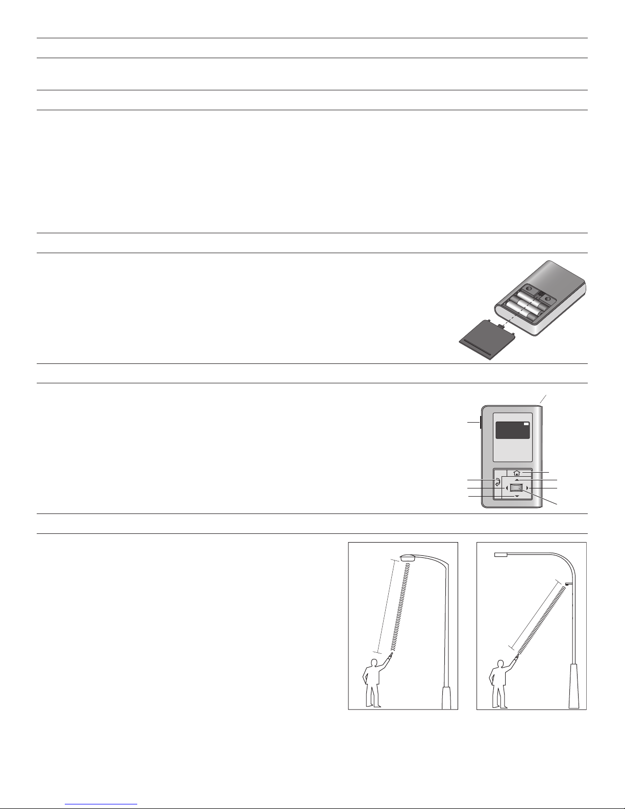
IR communication can be affected by the mounting height of the sensor
and high ambient lighting such as direct daylight or electric light such as
floodlights, and some halogen, fluorescent lamps, LED’s.
When trying to communicate with the FSP-211B, be sure to be positioned
under the sensor without any obstructions. Every time the commissionng
tool establishes communication with the FSP-211B, the controlled load
will cycle.
15'-32'
Power
On/Off
Back
Left
Down
FSP-2X1
HBP-111
BAT=
15'-32'
Home/Main
Menu
Up
3

TROUBLESHOOTING
Lights will not go to High Mode:
• Check all wire connections and verify the load and the ground wires are tightly secured.
• Make sure that the sensor is not obstructed.
• Check light level parameter, to find out the amount of light that the sensor is detecting. Cover the sensor lens to simulate darkness
in the room. If the lights come ON, the setpoint needs to be adjusted. If set for minimum, more than 1 fc at the sensor of ambient
light will cause
the lights to be held OFF. See the new settings section for instructions.
• If lights still do not turn ON, call 800.879.8585 for technical support.
Lights will not go into Low Mode:
• The time delay can be set from a minimum of 30 seconds to a maximum of 30 minutes. Ensure that the time delay is set to the
desired delay and that there is no movement within the sensor’s view for that time period.
• To quickly test the unit operation, enable test mode and move out of the sensor’s view. Lights should fade to low mode after 5
seconds.
• If lights still do not fade to Low Mode, call 800.879.8585 for technical support
Lights will not turn OFF:
• Cut Off time may be set to “Disable.”
• Ensure that the Cut Off is set to the desired time and that there is no movement within the sensor’s view for that time period when
the lights are in Low Mode.
• To quickly test the unit operation, enable test mode and move out of the sensor’s view. Lights should fade to low mode after 5
seconds and the OFF (if cut off is enabled) after 10 sec.
• If lights still do not turn OFF, call 800.879.8585 for technical support.
False Triggering may occur if the sensor is exposed to high ambient temperature conditions and the unit is set to maximum sensitivity
for PIR detection.
• If this occurs, reduce the PIR sensitivity setting from maximum to a medium point and re-check unit operation.
• If experiencing false triggering during fade down/Off, try increasing the fade time.
Lights do not turn ON:
Check for blinking red LED. If the LED blinks twice, the sensor has reached its Hold Off setpoint, if the LED blinks 3 times, the sensor
has reached its Photocell Light Level setpoint.
Lights suddenly turn off and will not come back on:
Check for blinking red LED. If the LED blinks twice, the sensor has reached its Hold Off setpoint, if the LED blinks 3 times, the sensor
has reached its Photocell Light Level setpoint.
There is no IR communication:
Perform a power cycle on the FSP-211B.
OPERATION DURING POWER-UP
During the sensor warm-up period, which can last up to 5 seconds after initial power-up (or after a lengthy power outage), the load will
remain ON until the selected time delay expires.
ORDERING INFORMATION
Catalog # Description
FSP-211B Single/ Dual Phase, PIR Fixture Integrated Sensor in IP66 Enclosure
FSP-211B-S Single/ Dual Phase, PIR Fixture Integrated Sensor in IP66 Enclosure, with Straight Nipple Mount
FSP-211B-D Single/ Dual Phase, PIR Fixture Integrated Sensor in IP66 Enclosure, with Drop Nipple Mount
FSIR-100 Configuration Tool
FSP-L2 360° lens, up to 44’ diameter at 8’ height
FSP-L3 360° lens, up to 40’ diameter at 20’ height
FSP-L7 360° lens, up to 100’ diameter at 40’ height
FSP-C1 Small skirt, for use with FSP-L2 and FSP-L3 lenses
FSP-C2 Large skirt, for use with FSP-L7 lens
Sensor colors indicated by one of the following suffixes at the end of the catalog #:
-W = White; -BL = Black; -BR = Bronze/Brown; -G = Gray/Silver
4
 Loading...