

LEGRAND Wattstopper FD-301 Installation Instructions Manual
Wattstopper
®
Fixture Integrated Dimming Photosensor
No: 24625 – 09/16 rev. 1
Installation Instructions • Instructions d’Installation • Instrucciones de Instalación
Catalog Number • Numéro de Catalogue • Número de Catálogo: FD-301
Country of Origin: Made in China • Pays d’origine: Fabriqué en Chine • País de origen: Hecho en China
SPECIFICATIONS
Power Supply ................... 24VDC from Wattstopper FS-PP
Current Consumption .................................. 30mA@24VDC
Ballasts .................................... 0-10VDC dimmable ballasts
Wire Length, photosensor to ballast and FS-PP ..... 6’ (182cm)
Maximum Ballasts Controlled ...........................................50
Max Sink current .........................................................50mA
Min Signal to ballast ................................................ 0.2VDC
Max Signal to ballast .................................................. 0VDC
DESCRIPTION AND OPERATION
The FD-301 is a fixture-integrated dimming photosensor. It provides a continuous dimming signal to a 0-10VDC dimming ballast, based
on daylight level. It is a low voltage device used in conjunction with a Wattstopper FS-PP power pack. The FD-301 is a “closed loop”
system; it considers both daylight and electric light when determining dimming levels. It uses a sliding setpoint control algorithm to
maintain the desired illuminance levels for separate night and day target setpoints. The FD-301 slowly raises or lowers the electric lights
to avoid sudden changes that can annoy occupants. After the photosensor-equipped fixture is installed, final setup adjustments are
made using the LSR-301-S remote control setup tool. After commissioning, the FD-301 automatically adjusts the electric lights to meet
target illuminance levels.
Additional Control Options
Manual or Automatic ON/OFF lighting control can be provided by a switch or fixture integrated
occupancy sensor connected to the FS-PP (see Figures 5 and 6 for wiring). Occupant
Light Fixture
dimming control is provided by the optional LSR-301-P. This remote control allows the
occupant to temporarily adjust light levels.
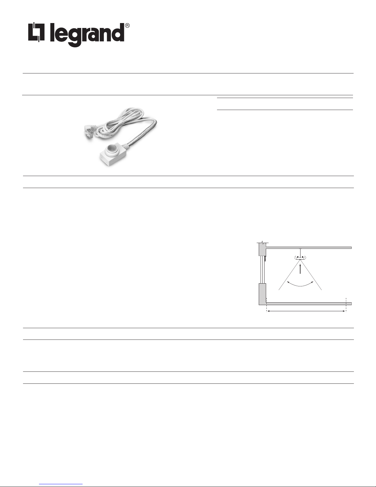
Photosensor Placement
The FD-301 photosensor works with 0-10VDC dimming ballasts to control lights in areas that
Window
FD-301
70º
Field of view
receive enough daylight so that the electric lights can be dimmed.
• Avoid installing photosensor-equipped fixtures where the light from one controlled fixture
spills over into the view of the next photosensor.
• Avoid locating photosensor-equipped fixtures close to specular surfaces such as highly
polished floors or tables, or highly reflective surfaces such as tops of cabinets, and others.
Typical Daylit Zone, about 12' (3.6m)
Figure 1: Placement
LAMP BURN-IN
Follow the lamp manufacturer’s recommendation on lamp burn-in for new lamps prior dimming the lamps with the FD-301. If the lamp
manufacturer’s guidelines are not followed, premature lamp failure may occur. After the fixture is installed and power is supplied to the
FD-301, it will drive the lamps at full output until the Night adjustment has been completed using the LSR-301-S remote control. See the
Photosensor Commissioning section for more information.
PHOTOSENSOR COMMISSIONING
The FD-301 is commissioned under two conditions, Night and Day. Either adjustment may be completed first. The red LED under the
FD-301’s lens flashes continuously until the Night and Day adjustments are both completed, then it can begin automatic dimming.
Conditions for Setup
Set up the FD-301 after all furnishings are installed. Placement of furnishings affects the way light reflects from various surfaces.
• Furniture, floor, and wall coverings must be installed and clean.
• All light fixtures must be installed and fully operational.
• Window coverings must be installed, clean, and operable.
• Remove unnecessary objects such as tools and installation materials from the view of the FD-301.
• Do not block primary sources of electric light or daylight from reaching the FD-301’s view.
Window blinds: If installed in the area, adjust them to maximize daylight while not allowing direct beam sunlight to enter the controlled
%XWWRQDFWLYDWLRQ
/('
Button activation
area. At night, adjust them so they block lighting from outdoor fixtures.
Lights from other areas: If non-dimmed lights in adjoining areas contribute to the light viewed by the FD-301, these lights must be on
during both Day and Night adjustments.
Target Illuminance Levels
Determine the illuminance required in the controlled space. In some applications, a footcandle target may be specified for the controlled
space. If this is the case, use a light meter to take measurements before and during the commissioning process. Choose a reference
location in the controlled area that is most likely to have the lowest illuminance level when daylit, and is located farthest from the window
or skylight. If the illuminance level is too low, select another location, or measure the illuminance level on a brighter day. If no target
illuminance is specified, adjustments can be based on user perception or preferences.
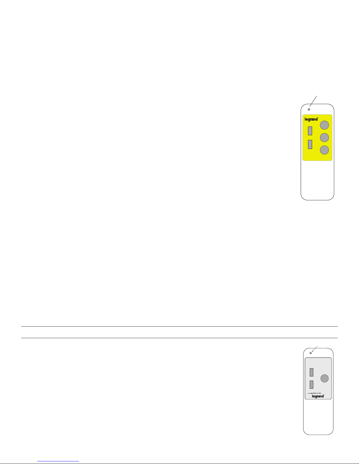
Adjustment Procedure
Initial adjustments to the FD-301 are done using the LSR-301-S remote control. The LSR-301-S has 5 buttons. The
LED on the remote control should light every time you press a button. The FD-301’s green LED also flickers for the
duration of the press.
p (up arrow) Press to increase light output.
q (down arrow) Press to decrease light output.
Night: Press to begin and end the Night adjustment process.
Auto: Press to begin automatic dimming.
Day: Press to begin and end the Day adjustment process.
Day Adjustment
Make this adjustment when daylight is providing illumination that is typical of the daytime conditions at the reference
location in the controlled area.
1. Press the Day button once. The FD-301’s green LED flickers.
2. Press p or q to adjust the electric lights to the appropriate light level.
If an illuminance target is specified by the lighting designer, use a light meter at the workplane to verify the
footcandle value.
3. Once the appropriate illuminance level is reached, press and HOLD the Day button for 3 seconds. The FD-301
acknowledges setting of the Day target setpoint by lighting the green LED twice for 3 seconds each time.
Night Adjustment
Make this adjustment when there is no daylight illumination at the reference location. To complete the night commissioning during the
day, the night environment must be simulated by blocking all sources of daylight.
1. Press the Night button once. The FD-301’s green LED flickers.
2. Press p or q to adjust light level.
If an illuminance target is specified by the lighting designer, use a light meter at the workplane to verify the footcandle value.
3. Once the target level has been reached, press and HOLD the Night button for 3 seconds. The FD-301 acknowledges setting of
the Night target setpoint by lighting the green LED twice for 3 seconds each time.
Figure 2a:
LSR-301-S setup tool
S
S
/6
3KRWRVHQVRU
6HWXS7RRO
/656
1LJKW
$XWR
'D\
Begin Automatic Dimming
To immediately begin automatic dimming after the Night and Day adjustments are BOTH completed, press the Auto button. Otherwise,
ten minutes after the last adjustment keypress (Step 3):
• If only Night is done, the signal to the ballast remains at the level to which it was adjusted and the red LED continues to flash.
• If only Day is done, the signal to the ballast goes to full output (10VDC) and the red LED continues to flash.
• If Night and Day are done, the FD-301 begins automatic dimming.
USER DIMMING CONTROL
Using the LSR-301-P, the user can raise the target illuminance level by up to 25% of the target illuminance level set
with the LSR-301-S during commissioning, or reduce it to the lamp/ballast minimum. Pressing the p (up arrow) or q
(down arrow) temporarily raises or lowers the target illuminance level. The FD-301 controls the lights to maintain the
new target level until another button is pressed.
Pressing Auto cancels the user adjusted target illuminance level. The FD-301 returns to automatic dimming using the
levels set with the LSR-301-S.
Figure 2b:
LSR-301-P occupant remote
2
Lighting Control
p
p
p
p
LED
Auto
 Loading...