

LEGRAND Wattstopper EW-200-120, Wattstopper EW-200-277 Installation Instructions Manual
Wattstopper
KRXVLQJ
6HQVRU
OHQV
$WWDFKPHQW
Outdoor PIR Motion Sensors
®
No: 24259 – 04/18 rev. 1
Installation Instructions • Instructions d’Installation • Instrucciones de Instalación
Catalog Numbers • Les Numéros de Catalogue • Los Números de Catálogo: EW-200-120, EW-200-277
Country of Origin: Made in China • Pays d’origine: Fabriqué en Chine • País de origen: Hecho en China
&RYHU
SODWH
6HQVRU
KROHVZLWK
SOXJV
Box Contents
• One (1) EW-200-120, EW-200-277
• Accessory bag:
Cover plate for 4" round outdoor junction box, with two cover
plate attachment hole plugs, cover plate gasket, cover plate
screws & screw covers (4 ea), lens mask, wire nuts (3)
• Installation instructions
Please read all of the installation instructions before installing this
product.
Voltage:
EW-200-120 ......................................................120VAC, 60Hz
EW-200-277 ......................................................277VAC, 60Hz
Mountable Locations ........................... Wall, ceiling or under eaves
Operating Temperature ........................ -40° to 130°F (-40° to 55°C)
Lens Coverage: ......................................................................... 270°
Load Ratings .....................0–1000W ballast or tungsten @120VAC
.....................................................0–1000W ballast @277VAC
Motor Load: ............................................................1/6 HP @20VAC
.....................................................................1/3 HP @277VAC
Current Consumption
Without Isolated Relay .......................................... 22 mA max.
With Isolated Relay ............................................... 34 mA max.
Time Delay Adjustment ............................................. 12sec.–16min.
Light Level Adjustment ............................................... 0.5FC–200FC
Isolated Relay on EW-200 (both -120 & -277 models)
Normally Open & Normally Closed contacts.
Isolated Relay Rating: ........................................... 1A @ 30VAC/DC
UL 773A Raintight Rated
IEC-IP-55 RateD
U.S.Patents: 4,787,722; 5,640,113
SPECIFICATIONS
THIS UNIT USES HIGH VOLTAGE. IT SHOULD ONLY BE INSTALLED BY QUALIFIED PERSONS THAT ARE THOROUGHLY FAMILIAR
WITH PROPER SAFETY PROCEDURES AND ELECTRICAL AND BUILDING CODES FOR THE INSTALLATION LOCATION.
TO AVOID FIRE, SHOCK, ELECTROCUTION, OR DEATH.TURN OFF POWER AT THE CIRCUIT
BREAKER OR FUSE BOX AND TEST TO ENSURE POWER IS OFF BEFORE WIRING.
The EW sensors are outdoor passive infrared (PIR) motion sensors rated for wet conditions. They are preassembled with a junction box
cover and are ready to install to standard round outdoor junction boxes.
The EW sensors utilize advanced PIR technology and a superior lens design to detect motion. PIR sensing is passive, and detects the
difference between infrared energy in motion and the background space.
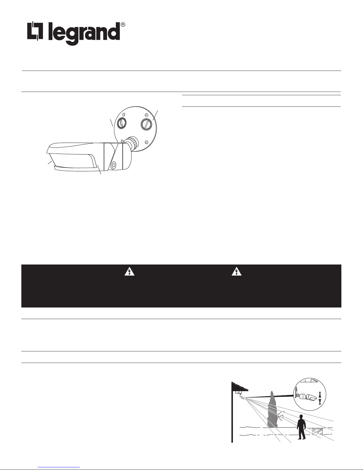
Coverage is shown as tested in a controlled setting with the unit mounted at 8
ft at a 10° tilt from the horizontal surface. The actual outside coverage pattern
may vary substantially at the specific installation site and is dependent on
several factors including weather conditions, external light sources, mounting
height and sensor tilt.
Coverage adjustment:
The front of the sensor housing can be moved
up and down for easy coverage adjustment.
WARNING
UNIT DESCRIPTION
COVERAGE PATTERN
(3m)
(8m)
t
(16m)
View
COVERAGE PATTERN (CONT’D)
Top
View
90
Masking:
Opaque adhesive tape is supplied
so that sections of the sensor’s
lens can be masked to restrict
coverage in unwanted areas.
EW-200
270° coverage
(2.4m)
Side
8ft
9.5ft
25ft
52.5f
MOTION SENSOR PLACEMENT
Mounting Options
• Install onto a standard 4” round outdoor junction box.
• Mount to a flat, stable, vibration-free surface.
• Mount vertically or horizontally, usually to a wall, ceiling or under an eave.
Careful consideration must be given to sensor placement. PIR sensors detect the difference between infrared energy in motion and the
background space. To be detected, a person or vehicle must be within the sensor’s coverage pattern and have an unobstructed view of
the sensor.
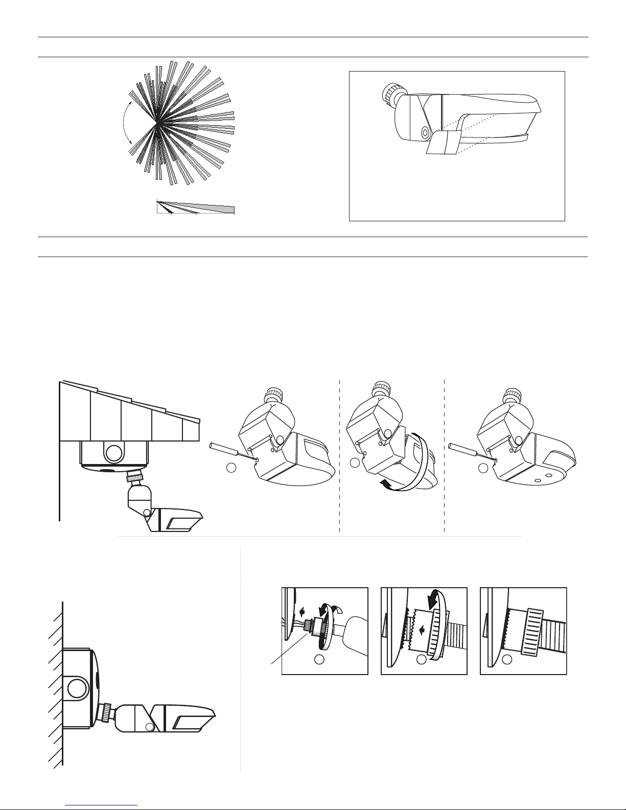
Horizontally Mounted:
For horizontal mounting, such as under eaves, rotate the sensor housing as shown in the diagrams below. Make sure that the
gasket is seated properly.
Vertically Mounted:
The sensor comes assembled
and ready for vertical cover
plate mounting, as shown in
the illustration below.
1
Loosen the two screws at the
back of the sensor.
Attach mounting post to the cover plate:
Make sure that the O-ring is on the threaded end of the mounting post
before installing.
O-ring
Lightly screw the
mounting post into
the cover plate by
rotating the sensor.
2
Rotate the sensor
housing 180°.
Adjust the sensor
to the desired
angle, then tighten
the locking ring.
3
Replace and tighten the screws.
Locking ring and collar
must be securely seated
against the cover plate
locking ring.
2
 Loading...