

LEGRAND Wattstopper DLM LMJA-8 Series, Wattstopper LMJA-8125, Wattstopper LMJA-8125-AX, Wattstopper LMJA-8300, Wattstopper LMJA-8300-AX Installation Instructions Manual
Wattstopper
DLM LMJA-8xxx Network Controller
®
No: 28957 – 8/19 rev. 2
Catalog Numbers • Les Nombre de Catalogue • Números de Catálogo: LMJA-8125, LMJA-8300/LMJA-8125-AX, LMJA-8300-AX
Country of Origin: Made in China • Pays d’origine: Fabriqué en Chine • País de origen: Hecho en China
Installation Instructions • Instructions d’Installation • Instrucciones de Instalación
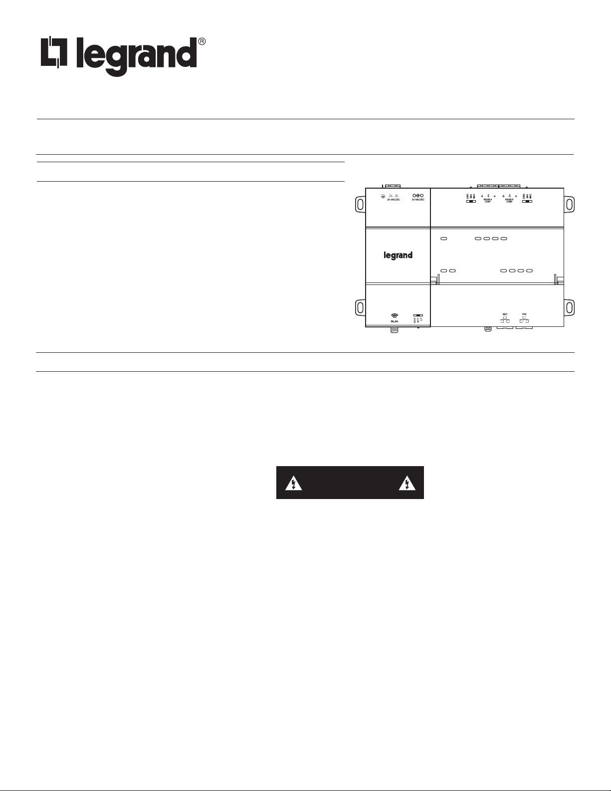
OVERVIEW
The Legrand/Wattstopper LMJA-8125/LMJA-8300 is a network controller
that provides advanced building management and automation features for
customers using Digital Lighting Management (DLM) BACnet-based networks
and devices. Powered by the Tridium Niagara platform, the controller can
be ordered with either the N4 or AX 3.8 (LMJA-8xxx-AX) Segman 2.4
station. The LMJA-8xxx Network controller hardware running are licensed
for use with Wattstopper DLM. When used with a DLM wired or wireless
network segments the LMJA-8xxx series network controllers provide global
control, monitoring, adjustment, scheduling, and support for graphics. Larger
buildings and campus deployments with multiple network controllers can
also communicate to a supervisor software for a single point of BACnet
management and monitoring. The LMJA-8xxx series can be configured to
work with just DLM platform or can be integrated into an existing 3rd party
Building Management System (BMS).
PREPARATION
Unpack the LMJA-8125/8300 controller and power module and inspect the package contents for damaged or missing components. If
damaged, notify the appropriate carrier at once and return any damaged components for immediate repair or replacement.
Included in this Package
Included in this package you should find the following items:
• (1) DLM LMJA-8125/8300 controller unit with micro SD card
• (1) Controller power supply
• (1) Wattstopper DLM quick reference guide
• (1) Wattstopper installation sheet (28957)
• (1) Accessory wiring and connector accessory pack
CAUTION
Safety Precautions
The following items are warnings of a general nature relating to the installation and start-up of the LMJA-8xxx. Be sure to heed these
warnings to prevent personal injury or equipment damage.
WARNING
• Disconnect power before installation or servicing to prevent electrical shock or equipment damage.
• Make all connections in accordance with national and local electrical codes. Use copper conductors only.
• To reduce the risk of fire or electrical shock, install in a controlled environment relatively free of contaminants.
• This device is only intended for use as a monitoring and control device. To prevent data loss or equipment damage, do not
use it for any other purpose.
Static Discharge Precautions
Static charges produce voltages high enough to damage electronic components. The microprocessors and associated circuitry within a
Segment Manager are sensitive to static discharge. Follow these precautions when installing, servicing, or operating the system:
CAUTION
• Work in a static-free area.
• Discharge any static electricity you may have accumulated. Discharge static electricity by touching a securely grounded
object.
• Do not handle the printed circuit board (PCB) without proper protection against static discharge. Use a wrist strap when
handling PCBs. The wrist strap clamp must be secured to earth ground.
1
PREPARATION (continued)
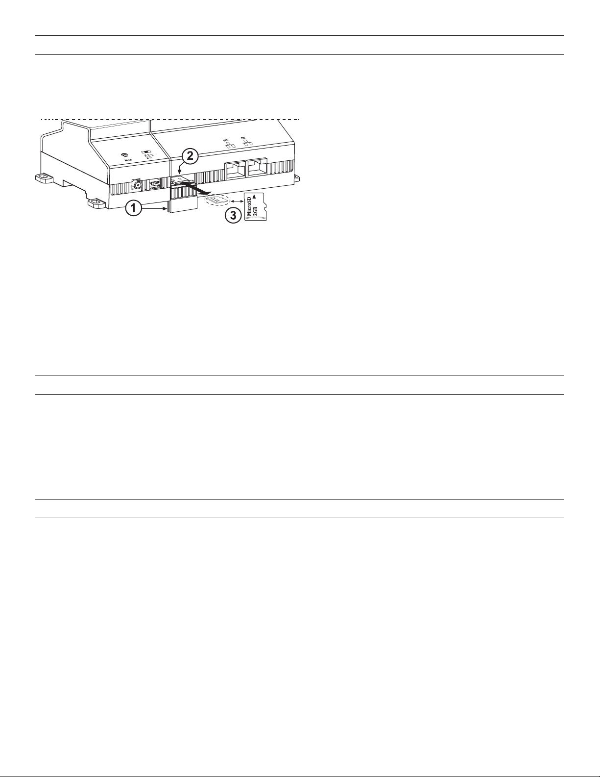
Inserting or Removing the Micro SD Card Installation
Before mounting a new controller, you must insert the included microSD ash memory card. Note the card has the unique Niagara
identity (host ID) for the unit, set at the factory. ALL power to the controller must be removed. If the unit is currently running, initiate a
controller shutdown.
1. Access shutter for microSD card (slide down/up to
open/close)
2. Card carrier inside controller
3. MicroSD card to insert or remove from card carrier
1. Carefully slide the plastic microSD card shutter open. The shutter should remain captive in the base, revealing the microSD card
socket.
2. To insert the microSD card, slide it into the card carrier, label side up, until the spring catch engages. If properly inserted, the card is
behind the shutter track.
3. To remove the microSD card, push it in, until the spring release pushes it partially out of the card carrier. Grasp the card, pull it
completely out of the unit and store it in a static-free protective case.
4. Carefully slide the card shutter back over the card carrier opening, until it clicks into place. When properly closed, the shutter should
not protrude behind the mounting base.
NOTE: Data on the microSD card is encrypted. If you swap in a card from a previously configured unit, you must change the LMJA-
8125/8300 system passphrase on the platform to match the passphrase on the new microSD card. Typically, the microSD card never
needs removal. However, in the case where a controller has been electrically damaged or found faulty, you can remove the card and
install it in another like unit, so it can become a functional replacement.
MATERIAL AND TOOLS REQUIRED
• One of the following:
▸ UL Listed, Class 2, 24VAC transformer, rated at minimum of 24VA. A dedicated transformer is required (cannot power additional
equipment), -OR ▸ 24VDC power supply, capable of supplying at least 1A (24W), -OR-
▸ NB-PS1 wall-mount AC power adapter with barrel connector plug
• DIN rail, type NS35/7.5 (35mm x 7.5mm_ and DIN rail end-clips (stop clips), recommended for any installation with option modules.
Controller is also panel mountable.
• Suitable tools, fasteners, and accessories for mounting
MOUNTING
Mount the LMJA-8125/8300 controller in a location that allows clearance for wiring, servicing, and module removal.
Environmental Requirements
Note the following requirements for the LMJA-8125/8300 controller mounting location:
• This product is intended for indoor use only. Altitude to 6,562 ft (2,000m).
• Ambient conditions must be within the range of: Operating Temperature: -4°F to 140°F (-20°C to 60°C), Storage Temperature: -40°F
to 185°F (-40°C to 85°C)
• Relative Humidity: 5% to 95% non-condensing, Pollution Degree 3
• Supply (mains) voltage requirements: Allowable voltage fluctuation +/- 10%
• Do not expose the unit to ambient conditions outside of the range of 0ºC (32º F) to 50ºC (122º F) and relative humidity outside the
range 5% to 95% non-condensing.
• If mounting inside an enclosure, that enclosure should be designed to keep the unit within its required operating range considering
a 24-watt dissipation by the controller, plus dissipation from any other devices installed in the same enclosure. This is especially
important if the controller is mounted inside an enclosure with other heat producing equipment.
• Do not mount the unit:
▸ In an area where excessive moisture, corrosive fumes, or explosive vapors are present
▸ Where vibration or shock is likely to occur
▸ In a location subject to electrical noise, including the proximity of large electrical conductors, electrical machinery, welding
equipment, spark igniters, and variable frequency drives, etc.
2
MOUNTING (continued)
Physical Mounting
The following information applies to physically mounting the unit.
• You can mount the LMJA-8125/8300 in any orientation. Horizontal mounting (as shown) is strongly recommended to achieve
maximum heat dissipation and meet the operating temperature upper limit. Any other mounting orientation reduces this upper limit.
• Mounting on a 35mm wide DIN rail is recommended. The LMJA-8125/8300 unit base has a molded DIN rail slot and locking clip.
DIN rail mounting ensure alignment of the connectors between all devices.
• If DIN rail mounting is impractical, you can use screws in mounting tabs on the controller (see next page)
• The LMNC-ENC1 is an optional DIN rail equipped enclosure. The LMNC-ENC1 provides an integral 120VAC receptacle, conduit
connection points and protection for the LMJA-8xxx. It is designed for applications where code or the local AHJ requires that low
voltage wiring such as control and communication wiring be run inside conduit, or where needed for customer specifications. See
the instructions provided with the LMNC-ENC1 for more information.
• The LMJA-8125/8300 controller can also be mounted in an LMNC enclosure, where multiple NB-Routers and an NB-Switch are
used
NOTE: To remove a unit from the DIN rail, pull
down its locking clip, then swing the bottom
out and lift the unity away from the DIN rail.
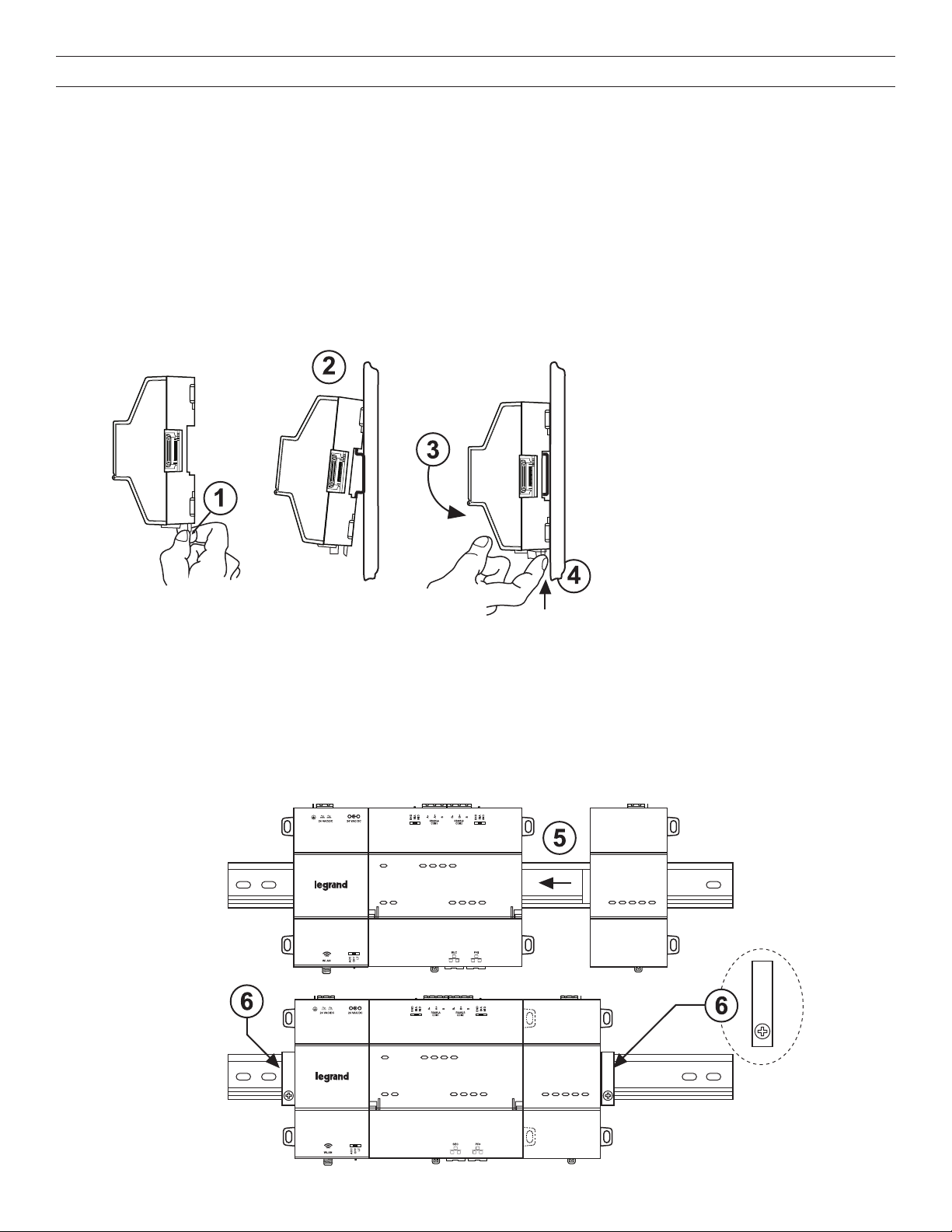
To mount on third-party DIN rail
The following procedure provides step-by-step DIN rail mounting instructions for the LMJA-8125/8300. It is recommended to leave 2
inches of clearance above and below the unit.
1. Pull the controller’s locking clip down.
2. Tilt the controller to hook over the DIN rail.
3. Push down and in on the unit, fastening to the rail.
4. Push the locking clip up to secure.
5. Mount any option module (RS-485 Module) onto the DIN rail in the same way.
6. Carefully secure both ends of the final assembly with DIN rail end-clips provided by the DIN rail vendor.
3
MOUNTING (continued)
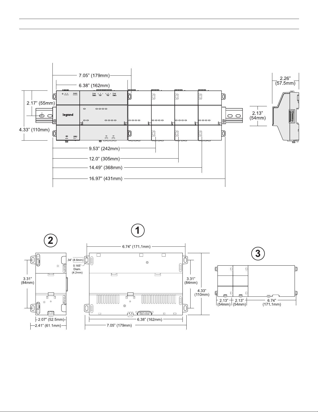
DIN Rail Mounting Dimensions
This diagram shows mounting dimensions of controller and option modules. Electronic and printed versions of this guide may not show
the dimensions to scale. Verify all measurements before drilling.
Tab Mounting Dimensions
Measurements shown below are in inches and (mm). NOTE: DIN rail mounting is recommended over tab mounting.
1. The LMJA-8125/8300 controller. With no option modules added, allow at least 1.5” (38mm) clearance around all sides.
2. Optional expansion module. Up to four (4) may be used.
3. Distances between center of tabs from one unit to another unit.
4

INITIAL LOGIN AND SET UP - AX 3.8 (SEGMAN 2.4)
Make sure that you have followed all installation instructions and that the controller is properly powered and connected to the segment
network(s).
1. Connect a PC to the LAN 1 connection on the LMJA-8xxx-AX using a standard Ethernet cable (not supplied). Note that some
older PCs require the use of a crossover cable for this connection.
2. Confirm that the LED labeled PRI is lit on the top of the LMJA-8xxx-AX housing. This indicates that an Ethernet connection is present.
Confirm that the link indicator on the PC’s NIC is also lit. If both are not lit, try using another cable or try using a crossover cable.
3. Set the network adapter in your PC to use a static IP address in the same range as the LMJA-8xxx_AX. Set the PC to
192.168.1.xxx (where xxx is any number between 001 and 255 and is not the same as the Segment Manager). Set the subnet
mask to 255.255.255.0. If you need assistance with this step, see the Static IP Address Setup on pages 6-7.
4. Open a browser on the PC and enter the following in the address field:
http://192.168.1.140.
5. Press ENTER. The browser displays a progress indicator while the Segment Manager 2.4 downloads a small application to the
PC. This process is only required the first time that you connect to the LMJA-8xxx-AX running Segment Manager 2.4.
6. When the Login window appears, enter the factory default login:
Username: SegMan
Password: w@ttstopper
Note that both the user name and password are case sensitive.
Click the “Login” button. Logins with individual permissions can be customized for different users. Refer to the Operation Manual
for setting up user logins.
7. The Segment Manager 2.4 Home screen opens in the browser window. Refer to the Operation Manual for further set up and
operation of the Segment Manager 2.4.
INITIAL LOGIN AND SET UP - N4
Make sure that you have followed all installation instructions and that the controller is properly powered and connected to the segment
network(s).
1. Connect a PC to the LAN 1 connection on the LMJA-8xxx using a standard Ethernet cable (not supplied). Note that some older
PCs require the use of a crossover cable for this connection.
2. Confirm that the LED labeled PRI is lit on the top of the LMJA-8xxx housing. This indicates that an Ethernet connection is present.
Confirm that the link indicator on the PC’s NIC is also lit. If both are not lit, try using another cable or try using a crossover cable.
3. Set the network adapter in your PC to use a static IP address in the same range as the LMJA-8xxx. Set the PC to 192.168.1.xxx
(where xxx is any number between 001 and 255 and is not the same as the Segment Manager). Set the subnet mask to
255.255.255.0. If you need assistance with this step, see the Static IP Address Setup on pages 6-7.
4. Open a browser on the PC and enter the following in the address field:
http://192.168.1.140.
5. When the Login window appears, enter the factory default login:
Username: admin
Password: W@ttst0pper
Note that both the user name and password are case sensitive.
5

STATIC IP ADDRESS SETUP
These instructions apply to Windows® 7, 8, or 10. Consult the appropriate documentation for other operating systems.
To set up the computer for direct connection to the Segment Manager, proceed as follows:
1. Click on the Start menu and type: network sharing center. Then Click on “Network and Sharing Center” in results.
2. Click Local Area Connection to open the Local Area Connection Status window.
3. Click Properties. In the Local Area Connection Properties window, select Internet Protocol Version 4 (TCP/IPv4).
6

4. Click Properties.
STATIC IP ADDRESS SETUP (continued)
5. Select Use the following IP address.
6. Enter the IP address and Subnet mask. Set the PC to 192.168.1.xxx (where xxx is any number between 001 and 255 and is not
the same as the Segment Manager). Set the subnet mask to 255.255.255.0.
7. Click OK then close all remaining windows.
7
 Loading...