

Page 1
Wattstopper
Line
V
r
Line
V
®
Power Pack
Bloc d’alimentation
No: 24566 – 11/17 rev. 2
Fuente de alimentación
Installation Instructions • Instructions d’Installation • Instrucciones de Instalación
Catalog Numbers • Les Numéros de Catalogue • Números de Catálogo: BZ-50/BZ-50RC
Country of Origin: Made in China • Pays d’origine: Fabriqué en Chine • País de origen: Hecho en China
BZ-50-U is BAA and TAA compliant (Product produced in the U.S.)
SPECIFICATIONS
Voltages ...........................................120/277VAC,50/60Hz
..................... 230/240 VAC (Single Phase), 50/60Hz
Load Requirements
Ballast, Incandescent ............ 20amp @120/277VAC
Eballast ........................................ 16amp @277VAC
Motor ......................................... 1HP @120/240VAC
Output .................225mA @24VDC (with relay connected)
Low Voltage Input
Control ON ...............................................12-24VDC
Operating Temperature .......................32°-104°F (0-40°C)
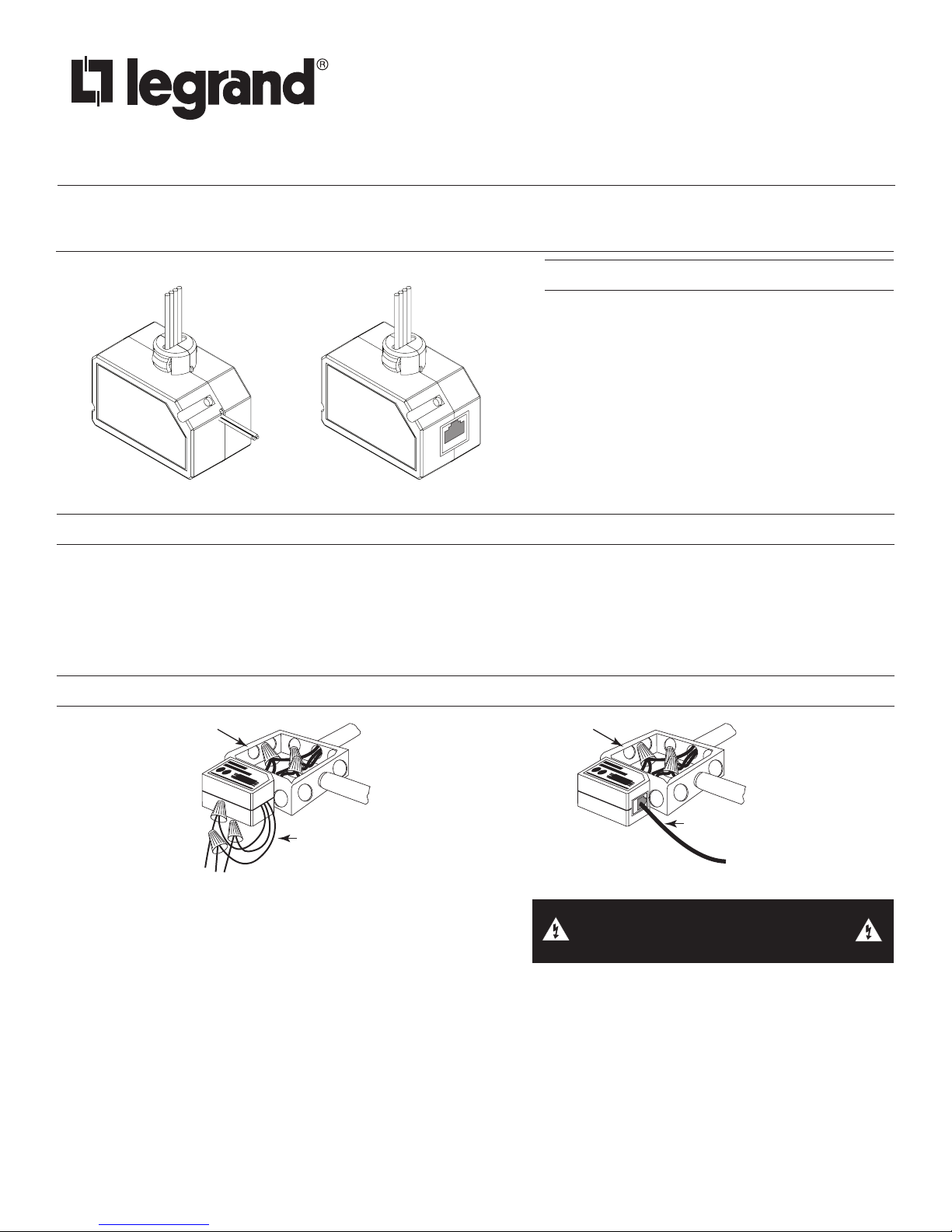
BZ-50 BZ-50RC
DESCRIPTION
The BZ-50 and BZ-50RC power packs are the foundation for any low voltage lighting control system. The BZ-50 and BZ-50RC supply
low voltage power to occupancy sensors and other control devices, switching line voltage in response to signals from control devices.
The power pack is attached to existing junction boxes or mounted into fixture wiring trays.
High voltage connections should use at least 14-gauge. For the BZ-50, low voltage wiring should use at least 22-gauge wire. The
BZ-50RC supplies low voltage power via shielded RJ45 cable. Always check local building codes. After initial wiring is complete,
check wiring diagram to verify power pack is wired correctly. Improper wiring can cause damage to power pack, lighting system, and
occupancy sensor.
INSTALLATION AND WIRING
oltage
Low Voltage
Class 2
BZ-50 BZ-50RC
1. Make sure power has been turned off at the circuit breaker.
2. Connect wires as shown in in the following diagrams, depending
on the model and application.
At least three sensors can be powered by the power pack.
oltage
Low Voltage cable
with RJ45 connecto
WARNING: TURN THE POWER OFF AT THE
CIRCUIT BREAKER BEFORE WIRING.
Installation Notes
1. Power packs should be installed in accordance with state, local and national electrical codes and requirements.
2. Power packs are designed to attach to existing or new electrical enclosures with 1/2 inch knockouts.
3. For the BZ-50, most applications require UL listed, 18-22 AWG, 3-conductor, Class 2 cable for low voltage wiring. For plenum
return ceilings, use UL listed plenum-approved cables.
For the BZ-50RC, connect an FS-C1 or FS-C3 cable between the RJ45 jack-equipped sensor and the BZ-50RC, as appropriate
for the distance between the sensor and power pack. Other cable accessories are shown in the Ordering information section.
NOTE: The BZ-50RC can connect to a sensor with standard wiring terminals by using an FS-C2 cable.
4. The BZ-50 BZ-50RC are Class 2 Output Power Supplies, suitable for parallel interconnection of up to 10 units maximum. These
powerpacks are UL Listed for Interconnection of Power Sources in accordance with the National Electric Code.
5. Refer to occupancy sensor data sheet to determine maximum number of sensors. Power pack mA output is 225mA.
Page 2
Neutral
Additional
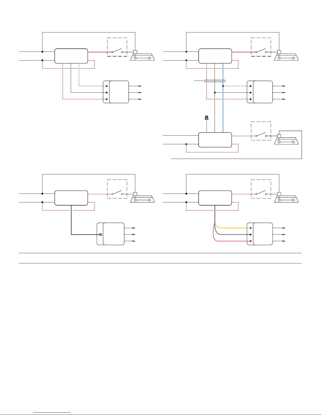
BZ-50 Single load control
4
splitter)
Additional
Sensor(s)
BZ-50 Parallel interconnect for multiple
load control from a single sensor
Neutral
Line
Neutral
Line
120VAC
277VAC
120VAC
277VAC
Optional
Local
Off
Switch
Any
24VDC
Ceiling/Wall
Sensor
Optional
Local
Off
Switch
White
Black
BZ-50
Power Pack
Red
Black
Red
Red
Blue
Control Output
Common
+24VDC
Optional
Local
Off
Switch
Any
24VDC
Ceiling/Wall
Sensor
Fixture
*To
Sensor(s)
Neutral
Line
Neutral
Line
120VAC
277VAC
Class 2
Low Voltage
Wires
120VAC
277VAC
White
Black
White
Black
BZ-50
Power Pack
Red
Black
Cap
Red
Black
BZ-50
Power Pack
Red
Red
Blue
Control Output
Common
+24VDC
Blue
Red
Red
BZ-50RC with sensor that has RJ45 jack BZ-50RC with standard sensor, using FS-C2 cable
White
Black
BZ-50RC
Power Pack
Red
Red
Optional
Local
Off
Switch
Fixture
Neutral
Line
120VAC
277VAC
White
Black
BZ-50RC
Power Pack
Red
Red
Optional
Local
Off
Switch
Fixture
Fixture
Fixture
*To
Additional
Sensor(s)
FS-C2
RJ45 Connection
Any
24VDC
Ceiling/Wall
Sensor with
an RJ45 Jack
*To
Additional
Sensor(s)
with RJ45 jacks
(requires FS-C
cable
Control Output
(Yellow)
Common (Black)
+24VDC (Red)
Any
24VDC
Ceiling/Wall
Sensor
*To
OPERATION
Low Voltage Input (Blue Wire for BZ-50, RJ-45 cable for BZ-50RC, Yellow Wire for BZ-50RC with FS-C2):
The low voltage input wire carries the +12-24VDC maintained input Control ON signal to the BZ-50. Applying 12-24VDC to this input
closes the BZ-50 load relay. Removing the voltage returns the relay to its normal state. This input is intended for sensor or control device
input.
Over Current Protection:
The BZ-50 contains built-in short circuit and thermal protection circuitry that shuts down the +24VDC output (red wire to sensors) to
prevent permanent damage to the power pack. Removing the excess load from the output restores the BZ-50 to proper operation. The
excess load can be connected to another power pack.
LED Indicator:
The LED indicates the following conditions on the BZ-50:
• LED OFF: no power to the BZ-50, or the +24VDC output is shorted.
• LED ON, blinks once every 5 seconds: the relay is closed (load ON).
• LED ON continuously: the relay is open (load OFF).
• LED blinking continuously: current output limit is exceeded (too many sensors are connected to the power pack); +24VDC output
shut down.
2
Page 3
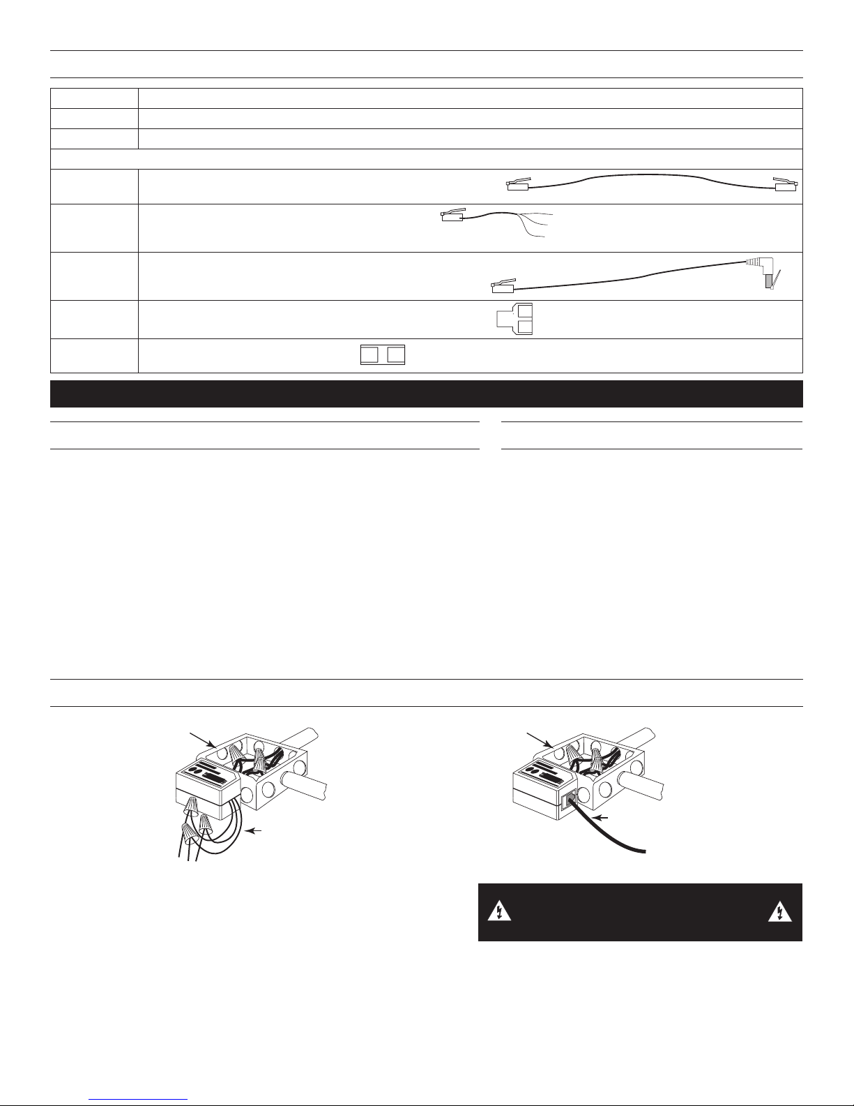
ORDERING INFORMATION
10' (3m)
6" (152mm)
3' (914mm)
Basse tension
Tension
de ligne
avec connecteur RJ45
Tension
de ligne
Catalog No Description
BZ-50 Power Pack: 120/277VAC, 50/60Hz, 20A ballast or incandescent
BZ-50RC Power Pack: 120/277VAC, 50/60Hz, 20A ballast or incandescent with RJ-45 low voltage output
BZ-50RC Accessories
FS-C1 One 10’ cable with a shielded RJ45 male connector at each end
FS-C2 One 6” (152mm) cable with 3 flying leads at one end
and a shielded RJ45 male connector at the other
FS-C3 One 3’ cable with a shielded 90° RJ45 male connector at
one end and a shielded straight male RJ45 connector at the
other end, for space-limited areas
FS-C4 Shielded RJ45 splitter with female to dual female receptacles
FS-C5 Shielded RJ45 male-to-male coupler
INSTRUCTIONS EN FRANÇAIS
DESCRIPTION
Les blocs d'alimentation BZ-50 et BZ-50RC assurent l'alimentation de tous
les systèmes de commande d'éclairage à faible tension. Les blocs BZ-50 et
BZ-50RC assurent l'alimentation à faible tension des détecteurs de présence
et d'autres appareils de contrôle, en modifiant la puissance de l'alimentation
secteur en fonction des signaux émis par les appareils de contrôle. Les blocs
d'alimentation peuvent être raccordés aux boîtes de raccordement existantes
ou être montés dans les chemins de câblage déjà en place.
Les raccordements haute tension doivent passer par des fils d'un calibre
minimal de 14. Le câblage basse tension pour le BZ-50 doit comprendre
au minimum des fils de calibre 22. Le BZ-50RC assure l'alimentation basse
tension à l'aide d'un câble RJ45 blindé. Toujours consulter les codes du
bâtiment régionaux. Après avoir installé le câblage initial, consulter le schéma
de câblage afin de vérifier que le bloc d'alimentation est correctement
raccordé. Un câblage inadéquat peut provoquer des dommages du bloc
d'alimentation, du système d'éclairage et du détecteur de présence.
INSTALLATION ET CÂBLAGE
CARACTÉRISTIQUES
Alimentation électrique ................120–277 VCA, 50/60 Hz
........................230/240 VCA (Monophasé), 50/60Hz
Exigences de charge
Ballast, Incandescent ............... 20 A à 120/277 VCA
Eballast .................................... 16 A à 120/277 VCA
Moteur ..................................... 1 HP à 120/240 VCA
Sortie ...............225 mA à 24 VCC (avec connexion relais)
Entrée basse tension
Régulation ACTIVÉE ................................ 12-24 VCC
Température de fonctionnement ....... 0 à 40 °C (32 à 104 °F)
Câble basse tension
Classe 2
BZ-50 BZ-50RC
1. Assurez-vous que le courant a bien été coupé au niveau du
disjoncteur du circuit.
2. Connectez les fils de la manière illustrée dans les diagrammes
suivants et en fonction du modèle et de l'application.
Au moins trois détecteurs peuvent être alimentés par le bloc d'alimentation.
Remarques concernant l'installation
1. Les blocs d'alimentation doivent être installés conformément aux codes de réglementation électrique et exigences régionaux et
nationaux.
2. Les blocs d'alimentation sont conçus pour être raccordés à des coffrets électriques neufs ou déjà existants dotés de débouchures
de 12,7 mm (0,5 po).
AVERTISSEMENT : COUPER LE
COURANT AU DISJONCTEUR PRINCIPAL
AVANT D’INSTALLER LE CÂBLAGE.
3
Page 4

3. Pour le BZ-50, dans le cas d'un câblage à faible tension, la plupart des applications nécessitent des câbles de classe 2 à trois
Détecteur(s)
Détecteur(s)
séparateur FS-C4)
Détecteur(s)
conducteurs, 18-22 AWG, certifiés UL. Dans le cas de faux-plafonds plénum, utiliser des câbles certifiés UL de type plénum.
Pour le BZ-50RC, connectez un câble FS-C1 ou FS-C3 entre le détecteur à connecteur femelle RJ45 et le BZ-50RC selon ce
qui est nécessaire pour couvrir la distance entre le détecteur et le bloc d'alimentation. Les autres accessoires pour le câble sont
présentés dans la section Renseignements pour les commandes.
NOTE: Le BZ-50RC peut être connecté à un détecteur avec des bornes de raccordement standard en utilisant un câble FS-C2.
4. Les blocs BZ-50 et BZ-50RC sont des blocs d'alimentation de classe 2. Ils peuvent être utilisés pour assurer l'interconnexion
parallèle de 10 unités maximum. Ces blocs ont obtenu la certification UL pour l'interconnexion de sources d'alimentation
conformément au Code électrique national (NEC).
5. Consultez la fiche technique du détecteur de présence pour déterminer le nombre maximal de détecteurs. La sortie en mA du bloc
d'alimentation est de 225 mA.
Contrôle de charge simple du BZ-50
Interconnexion parallèle du BZ-50 pour contrôle
de charge multiple à partir d’un seul détecteur
Interrupteur
d'arrêt local
optionnel
Tout
24VCC
Détecteur
Plafond/Muir
Interrupteur
d'arrêt local
optionnel
Neutre
Circuit
120VCA
277VCA
Blanc
Noir
BZ-50
Bloc d'alimentation
Noir
Rouge
Bleu
Rouge
Rouge
Sortie de
régulation
Commun
+24VCC
Interrupteur
d'arrêt local
optionnel
Tout
24VCC
Détecteur
Plafond/Muir
Luminaire
*Vers Autre
Neutre
Circuit
Neutre
Circuit
120VCA
277VCA
Classe 2
Basse tension
120VCA
277VCA
Neutre
Blanc
Noir
fils
Blanc
Noir
BZ-50
Bloc d'alimentation
Noir
Rouge
Marette
Rouge
Noir
BZ-50
Bloc d'alimentation
Bleu
Bleu
Rouge
Rouge
Sortie de
régulation
Commun
+24VCC
Rouge
Rouge
BZ-50RC avec détecteur qui a un connecteur femelle RJ45 BZ-50RC avec détecteur standard fonctionnant avec un câble FS-C2
Interrupteur
d'arrêt local
optionnel
Neutre
Circuit
120VCA
277VCA
Blanc
Noir
BZ-50
Bloc d'alimentation
Rouge
Rouge
Interrupteur
d'arrêt local
optionnel
Luminaire
Neutre
Circuit
120VCA
277VCA
Blanc
Noir
BZ-50RC
Bloc d'alimentation
Rouge
Rouge
Luminaire
*Vers Autre
Luminaire
Luminaire
Connexion RJ45
Détecteur
avec
connecteur
femelle RJ45
Entrée basse tension (l bleu pour BZ-50, câble RJ-45 pour BZ-50RC, l jaune pour BZ-50RC avec FS-C2) :
Le fil à basse tension transmet le signal d'alimentation positif +12-24 VCC à contact maintenu au BZ-50. L'application d'un courant 1224 VCC à cette entrée entraîne la fermeture du relais de commande du BZ-50. Couper le courant permet de ramener le relais à son état
normal. Cette entrée est prévue uniquement pour le courant d'un détecteur ou d'un appareil de contrôle.
Protection contre la surtension :
Le bloc BZ-50 comprend une protection incorporée à un circuit court et thermique qui éteint la sortie +24 VCC (fil rouge vers détecteurs)
pour éviter tout dommage permanent du bloc d'alimentation. Supprimer la charge excessive de la sortie permet au BZ-50 de reprendre
son fonctionnement normal. La charge excessive peut être connectée à un autre bloc d'alimentation.
*Vers détecteur(s)
supplémentaire(s)
avec connecteurs
femelles RJ45
(nécessite un
FONCTIONNEMENT
FS-C2
câble
Sortie de régulation
(Jaune)
Commun (Noir)
+24VCC (Rouge)
Tout
24VCC
Détecteur
Plafond/Muir
*Vers Autre
4
Page 5

Voyant DEL :
10' (3m)
6" (152mm)
3' (914mm)
Le voyant DEL du BZ-50 indique les états suivants :
• DEL ÉTEINTE: BZ-50 non alimenté ou présente un court-circuit au niveau de la sortie +24 VCC.
• DEL ALLUMÉE et clignotant toutes les 5 secondes: le relais est fermé (charge ACTIVÉE).
• DEL ALLUMÉE en continu: le relais est ouvert (charge négative).
• DEL clignotant en continu: dépassement de la limite du courant de sortie (trop de détecteurs sont connectés au bloc
d'alimentation); sortie +24 VCC. coupée.
RENSEIGNEMENTS POUR LES COMMANDES
N° de
catalogue
BZ-50 Bloc d'alimentation : 120/277 V c.a., 50/60 Hz, ballast ou incandescent 20 A
BZ-50RC Bloc d'alimentation : 120/277 VCA, 50/60 Hz, ballast ou incandescence 20 A avec sortie basse tension RJ-45
Accessoires pour le BZ-50RC
FS-C1 Un câble de 3 m (10 pi) avec un connecteur RJ45 mâle blindé
à chaque extrémité
FS-C2 Câble de 15,2 cm (6 po) avec 3 câbles volants à une extrémité
et un connecteur RJ45 mâle blindé à l'autre extrémité
FS-C3 Un câble de 0,9 m (3 pi) avec un connecteur RJ45 90° mâle
blindé à une extrémité et un connecteur RJ45 droit mâle blindé
à l'autre extrémité, pour les espaces étroits
FS-C4 Séparateur RJ45 blindé avec prises femelle/femelle double
FS-C5 Coupleur mâle/mâle RJ45 blindé
Description
5
Page 6

INSTRUCCIONES EN ESPAÑOL
Voltaje
de línea
con conector RJ45
Voltaje
de línea
DESCRIPCIÓN
Las fuentes de alimentación BZ-50 y BZ-50RC componen la base
de cualquier sistema de control de iluminación de bajo voltaje. Los
BZ-50 y BZ-50RC suministran alimentación de bajo voltaje a los
sensores de ocupación y otros dispositivos de control y cambian
el voltaje de la línea en respuesta a señales de los dispositivos
de control. La fuente de alimentación se conecta a las cajas de
conexiones existentes o se monta a las bandejas de cableado de la
luminaria.
Las conexiones de alto voltaje deben utilizar cables de por lo
menos un calibre 14. En el caso del BZ-50, el cableado de bajo
voltaje debe usar cables de por lo menos un calibre 22. El BZ50RC suministra energía de bajo voltaje a través del cable RJ45
blindado. Verifique siempre los códigos de construcción locales.
Después de completar el cableado inicial, verifique el diagrama
de cableado para comprobar que la fuente de alimentación esté
conectado correctamente. Un cableado incorrecto puede provocar
daños a la fuente de alimentación, el sistema de iluminación y el
sensor de ocupación.
INSTALACIÓN Y CABLEADO
ESPECIFICACIONES
Voltajes ...............................................120–277 VCA,50/60 Hz
..............................230/240 VCA (Monofásico),50/60 Hz
Requisitos de carga
Balasto, Incandescente ................. 20 A a 120–277 VCA
EBalasto ............................................... 16 A a 120 VCA
Motor ............................................. 1 HP a 120/240 VCA
Salida ........................225 mA a 24 VCC (con relé conectado)
Entrada de bajo voltaje
Control ENCENDIDO .....................................12-24 VCC
Temperatura de funcionamiento ..... 32 °F-104 °F (0 °C-40 °C)
Bajo voltaje
Clase 2
BZ-50 BZ-50RC
Cable bajo voltaje
1. Asegúrese de haber apagado el suministro eléctrico al disyuntor.
2. Conecte los cables tal como se muestra en los diagramas a continuación,
en función del modelo y de la aplicación.
La fuente de alimentación puede suministrar energía a por lo menos tres
ADVERTENCIA: DESCONECTE LA
ALIMENTACIÓN EN EL DISYUNTOR
ANTES DEL CABLEADO.
sensores.
Notas de la instalación
1. Las fuentes de energía deben instalarse según los códigos y requisitos eléctricos estatales, locales y nacionales.
2. Las fuentes de energía están diseñadas para conectarse a gabinetes eléctricos nuevos o existentes con troqueles de ½ pulgada.
3. Para el BZ-50, la mayoría de las aplicaciones requieren cables certificados por UL, de calibre 18 a 22, de 3 conductores, de Clase
2 para el cableado de bajo voltaje. Para techos con retorno en el pleno, utilice cables aprobados para pleno calificados por UL.
Para el BZ-50RC, conecte un cable FS-C3 o FS-C1 entre el sensor equipado con un conector RJ45 y el BZ-50RC, según
corresponda para la distancia entre el sensor y el fuente de alimentación. Otros accesorios para cables se muestran en la sección
Información para pedidos.
NOTE: El BZ-50RC puede conectarse a un sensor con terminales de cableado de serie mediante el uso de un cable FS-C2.
4. El BZ-50 y el BZ-50RC son fuentes de alimentación de salida Clase 2, ideal para conexiones paralelas de hasta 10 unidades
como máximo. Estos fuentes de alimentación están calificados por UL para la interconexión de fuentes de alimentación según el
Código Eléctrico Nacional.
5. Consulte la hoja de datos del sensor de ocupación para determinar la cantidad máxima de sensores. La salida de la fuente de
alimentación es 225 mA.
6
Page 7

Control de carga individual de BZ-50
ers Sensor(es)
n
onectores RJ45
Interconexión paralela de BZ-50 para el control
de varias cargas desde un solo sensor
Neutro
Línea
Neutro
Línea
Rojo
Rojo
control
Común
Rojo
Rojo
Interruptor
de Apagado
Local Opcional
Cualquiera
24VCC
Sensor para
Cielo raso/
Pared
Interruptor
de Apagado
Local Opcional
120VCA
277VCA
Blanco
Negro
Fuente de alimentación
Rojo
BZ-50
Negro
Azul
Rojo
Rojo
Salida de
control
Común
+24VCC
Interruptor
de Apagado
Local Opcional
Cualquiera
24VCC
Sensor para
Cielo raso/
Pared
Fixtura
*A Sensores
adicionales
Neutro
Línea
Neutro
Línea
120VCA
277VCA
Bajo voltaje
Conductores
120VCA
277VCA
Neutro
Blanco
Negro
Clase 2
Blanco
Negro
BZ-50
Fuente de alimentación
Azul
Rojo
Negro
Tuerca
de Cables
Rojo
Negro
Azul
BZ-50
Fuente de alimentación
Salida de
+24VCC
BZ-50RC con sensor que tiene un conector RJ45 BZ-50RC con sensor de serie que utiliza un cable FS-C2
Interruptor
de Apagado
Local Opcional
120VCA
277VCA
Blanco
Negro
Fuente de alimentación
BZ-50
Rojo
Rojo
Interruptor
de Apagado
Local Opcional
Fixtura
Neutro
Línea
120VCA
277VCA
Blanco
Negro
Fuente de alimentación
BZ-50RC
Rojo
Rojo
Fixtura
Fixtura
Fixtura
*A Sensores
adicionales
FS-C2
Conexión RJ45
Sensor con
un conector
RJ45
*V
adicional(es) co
c
(necesita un
divisorFS-C4)
cable
Salida de control
(Amarillo)
Común(Negro)
+24VCC (Rojo)
Cualquiera
24VCC
Sensor para
Cielo raso/
Pared
*A Sensores
adicionales
FUNCIONAMIENTO
Entrada de bajo voltaje (cable azul para BZ-50, cable RJ-45 para BZ-50RC, cable amarillo para BZ-50RC con FS-C2):
El cable de entrada de bajo voltaje transporta la señal de encendido del control de entrada mantenida en +12-24 V CC al BZ-50. Si se
aplica 12-24 V CC a esta entrada, se cierra el relé de carga del BZ-50. Cuando se elimina el voltaje, el relé vuelve a su estado normal.
Esta entrada está diseñada para entrada de sensor o de dispositivo de control.
Protección contra sobrecarga:
El BZ-50 contiene circuitos integrados de cortocircuito y de protección térmica que cierran la salida de +24 V CC (cable rojo a
sensores) para evitar daños permanentes a la fuente de alimentación. Si se elimina la carga excesiva de la salida, el BZ-50 vuelve a su
funcionamiento normal. La carga excesiva puede conectarse a otra fuente de alimentación.
Indicador LED:
El LED indica los siguientes estados del BZ-50:
• LED apagado: no hay alimentación al BZ-50, o la salida de +24 V CC está en corto.
• LED encendido, parpadea una vez cada 5 segundos: el relé está cerrado (carga encendida).
• LED encendido continuamente: el relé está abierto (carga apagada).
• LED parpadea continuamente: se supera el límite de salida de corriente (demasiados sensores están conectados la fuente de
energía); salida de +24 VCC apagada.
7
Page 8

INFORMACIÓN PARA HACER PEDIDOS
10' (3m)
6" (152mm)
3' (914mm)
N.° de
Descripción
catálogo
BZ-50 Fuente de alimentación: 120/277 V CA, 50/60 Hz, balasto o carga incandescente de 20 A
BZ-50RC Fuente de alimentación: 120/277 V CA, 50/60 Hz, balasto o incandescente de 20 A con una salida de bajo voltaje RJ-45
Accesorios BZ-50RC
FS-C1 Un cable de 10 pies con un conector macho RJ45 blindado en
cada extremo
FS-C2 Un cable de 6 in (152 mm) con 3 cables de interconexión en un
extremo y un conector macho RJ45 blindado en el otro
FS-C3 Un cable de 3 pies con un conector macho RJ45 de 90° blindado
en un extremo y un conector macho RJ45 recto blindado en el
otro extremo, para áreas con limitación de espacio
FS-C4 Divisor RJ45 blindado con hembra a receptáculos con dos hembras
FS-C5 Acoplador macho a macho RJ45 blindado
WARRANTY INFORMATION INFORMATIONS RELATIVES À LA GARANTIE INFORMACIÓN DE LA GARANTÍA
Wattstopper warranties its products to be free
of defects in materials and workmanship for a
period of five (5) years. There are no obligations
or liabilities on the part of Wattstopper for
consequential damages arising out of, or in
connection with, the use or performance of this
product or other indirect damages with respect
to loss of property, revenue or profit, or cost of
removal, installation or reinstallation.
No. 24566 – 11/17 rev. 2
© Copyright 2017 Legrand All Rights Reserved.
© Copyright 2017 Tous droits réservés Legrand.
© Copyright 2017 Legrand Todos los derechos reservados.
Wattstopper garantit que ses produits sont
exempts de défauts de matériaux et de fabrication
pour une période de cinq (5) ans. Wattstopper
ne peut être tenu responsable de tout dommage
consécutif causé par ou lié à l’utilisation ou
à la performance de ce produit ou tout autre
dommage indirect lié à la perte de propriété, de
revenus, ou de profits, ou aux coûts d’enlèvement,
d’installation ou de réinstallation.
Wattstopper garantiza que sus productos
están libres de defectos en materiales y mano
de obra por un período de cinco (5) años. No
existen obligaciones ni responsabilidades por
parte de Wattstopper por daños consecuentes
que se deriven o estén relacionados con el
uso o el rendimiento de este producto u otros
daños indirectos con respecto a la pérdida
de propiedad, renta o ganancias, o al costo
de extracción, instalación o reinstalación.
800.879.8585
www.legrand.us/wattstopper
 Loading...