

Page 1
T-Unit:
(Field Installation of the standard three-compartment tunnels,
bridges, and partitions.)
Installation of Tunnels and Bridges:
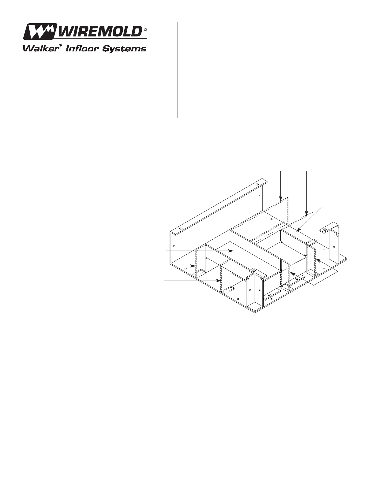
1. Position the tunnels in the T-unit as shown.
2. Using the holes in the tunnel flange as a
guide, drill 5/32" holes through the bottom
of the T-unit.
3. Mount the tunnels with the #10-16 X 1/4" long
screws provided.
NOTE: The tunnels and bridges may be welded in place.
4. Position the bridges in the T-unit
as shown.
5. Refer to steps 2 and 3
to secure the bridges.
Installation of Partitions:
1. If the partitions of the adjoining Wallduct
sections have not been installed when the
T-unit tunnels/bridges are assembled, cut
the partitions long enough to extend into
the T-unit and abut the tunnels/bridges
of the T-unit.
WARNING: Gaps between partitions, tunnels, or bridges must not
exceed 1/8" [3.2mm].
2. If the partitions of the adjoining Wallduct
sections have been installed prior to the
assembly of the T-unit tunnels/bridges,
cut partition pieces from excess straight
body partitions as shown on the drawing.
These pieces are required to fit between
the straight body partitions and the
tunnels/bridges of the T-unit.
Wallduct T- and X-Unit
Tunnels and Bridges
Three Compartment
INSTALLATION INSTRUCTIONS
Walker®electrical systems conform to and should be
properly grounded in compliance with requirements of
the current National Electrical Code or codes administered by local authorities.
All electrical products may present a possible shock
or fire hazard if improperly installed or used. Walker
electrical products bear the mark as UL Listed and/or
Classified and should be installed in conformance with
current local and/or the National Electrical Code. Look
for listing and/or classification mark on product label.
T- Unit – All Components Field Installed.
Bridge
Tunnel
Partitions
Partitions
Partitions
Page 2
Walker Systems, Inc.
1000 Innovation Drive, Williamstown, WV 26187
©
Copyright 2000 The Wiremold Company All Rights Reserved 1 000 675 1100
X-Unit:
(Field Installation of the standard three-compartment tunnels,
bridges, and partitions.)
Installation of Tunnels and Bridges:
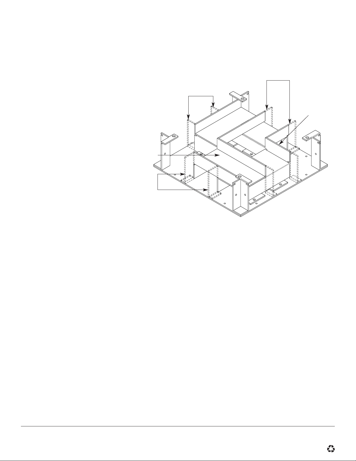
1. Position the tunnels in the X-unit as shown.
2. Using the holes in the tunnel flange
as a guide, drill 5/32" holes through
the bottom of the X-unit.
3. Mount the tunnels with the #10-16
x 1/4" long screws provided.
NOTE: The tunnels and bridges may be welded in place.
4. Position the bridges in the X-unit as shown.
5. Refer to steps 2 and 3 to secure the bridges.
Installation of Partitions:
1. If the partitions of the adjoining
Wallduct sections have not
been installed when the X-unit
tunnels/bridges are assembled,
cut the partitions long enough to
abut the tunnels/bridges of the X-unit.
WARNING: Gaps between partitions, tunnels, or
bridges must not exceed 1/8" [3.2mm].
2. If the partitions of the adjoining Wallduct
sections have been installed prior to the
assembly of the X-unit tunnels/bridges,
cut partition pieces from excess straight
partitions as shown on the drawing.
These pieces are required to fit between
the straight body partitions and the
tunnels/bridges of the X-unit.
X-Unit – All Components Field Installed.
Bridge
Tunnel
Partitions
Partitions
Partitions
 Loading...