

Page 1
INSTRUCTION / INSTALLATION SHEET
2X2 Enhanced Bi-Directional Video
Amplifier Module
301 Fulling Mill Road, Suite G
Middletown, PA 17057
Phone (800) 321-2343 / Fax (717) 702-2546
www.onqlegrand.com
1. INTRODUCTION
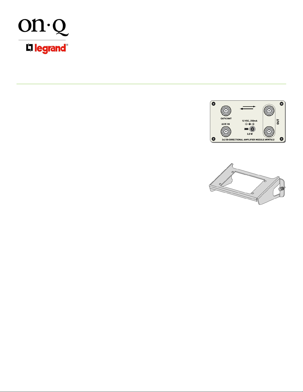
The On-Q/Legrand 2X2 Enhanced Bi-Directional Video Amplifier Module
(P/N VM7632) (see Figure 1) handles up to 9 inputs and 16 outputs when
installed with a 4, 6, or 8-way video module.
2.
DESCRIPTION
The Modular Video Amplifier is designed to distribute modulated internal
video signals and external video sources throughout the home. Combined
inputs are amplified to negate losses to the split outputs.
• Single bay horizontal mounting bracket (P/N AC1007) included for
mounting in On-Q style enclosure (see Figure 2)
• Bi-Directional amplifier which supports cable modem, digital
cable and video on demand
• Provides a 2nd input for internal signals.
• High gain amplifier that delivers quality signal to up to 8 TV
locations when coupled with add-on splitters such as
the On-Q/Legrand 1x4, 1x6 or 1x8 Passive Video Modules
• A manually adjustable attenuation circuit allows amplification of
video signals without noticeable degradation of signal quality while
connected to a +30dBmV CATV/ANT external input
IS-0345 Rev. B
Figure 1
Figure 2
POWER REQUIREMENTS
3.
The 2X2 Bi-Directional Video Amplifier Module's power requirements are:
• Voltage: +12 VDC
• Current: 250 mA
• Power: 3 W Max
• Polarity: Tip (+) Barrel (-)
Note: On-Q/Legrand offers several options for power, which range from a dedicated power cube designed to
accommodate one module to power solutions designed to accommodate multiple module installations.
Please refer to the On-Q/Legrand Catalog or the On-Q/Legrand website (http://www.onqlegrand.com) for more
information.
©Copyright 2006 by On-Q/Legrand All Rights Reserved. Page 1 of 2
Page 2
INSTRUCTION / INSTALLATION SHEET
2X2 Enhanced Bi-Directional Video
Amplifier Module
301 Fulling Mill Road, Suite G
Middletown, PA 17057
Phone (800) 321-2343 / Fax (717) 702-2546
www.onqlegrand.com
4. INSTALLATION
WARNING - to reduce the risk of fire or electric shock, do not expose this to rain or moisture.
Note to CATV Installer: This reminder is provided to call CATV systems installer’s attention to Section
820-40 of the NEC which provides guidelines for proper grounding and, in particular, specifies that the
cable shall be connected to the grounding system of the building, as close to the point of cable entr y as
practical.
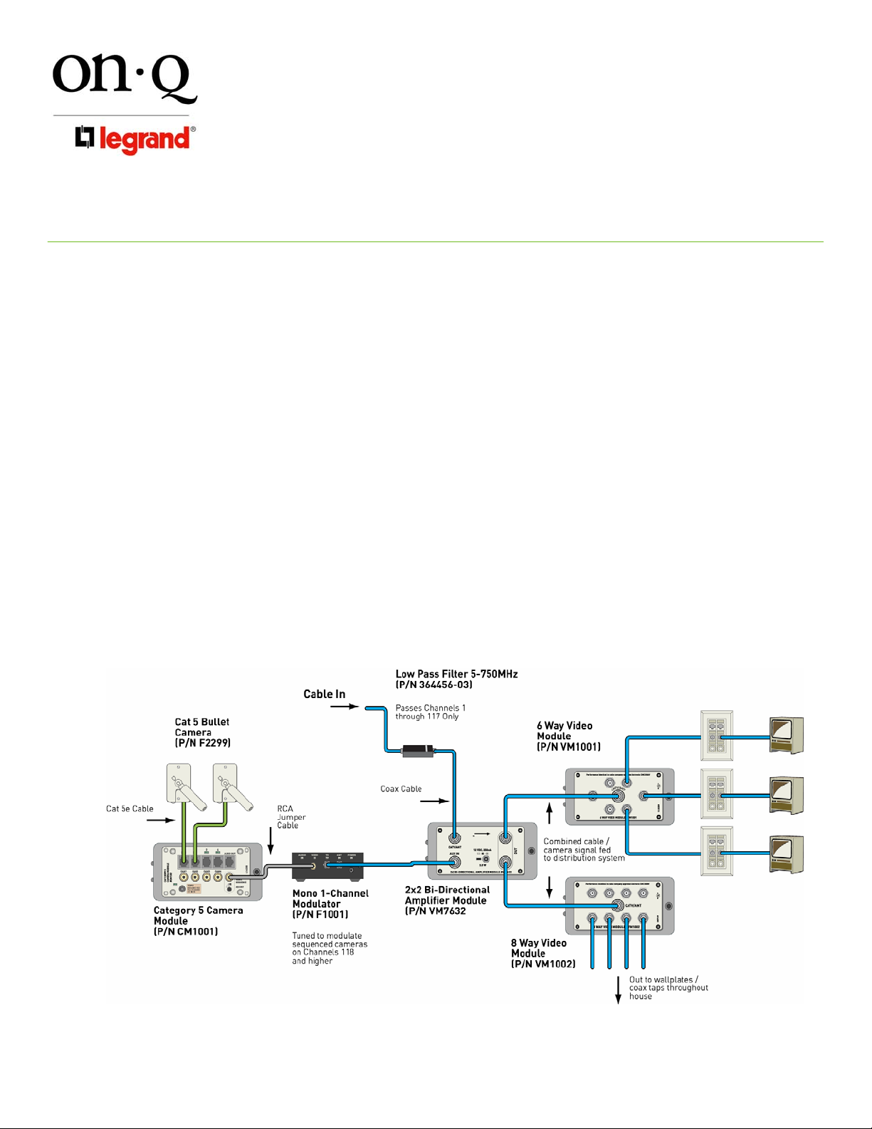
Refer to Figure 3 during installation.
A. Snap the 2x2 Video Amplifier onto the included bracket.
B. To mount the bracket (with module) into the enclosure, insert the tabs on the left side of the bracket into
the slots in the enclosure and push the bracket pushpin into an appropriate hole in the enclosu re to
secure the bracket (with module) to the enclosure.
C. Provide power to the amplifier module
D. Connect the incoming service line such as cable TV (CATV) or antenna (ANT) to the “CATV/ANT” port on
the amplifier.
E. Connect a coaxial patch cable from the “OUT” port on the 2x2 module to the “CATV/ANT” port on a 1x4,
1x6, or 1x8 passive video module to distribute the signal throughout the home.
F. To create an internal video network, connect all internal video sources to a separate 1x4, 1x6, or 1x8
passive video module. Connect a coaxial patch cable from the “CATV/ANT” port on the passive video
module to the “AUX IN” port on the 2x2 Modular Video Amplifier Module. This will make all internal video
sources viewable through all external ports on the passive video modules.
IS-0345 Rev. B
Figure 3
©Copyright 2006 by On-Q/Legrand All Rights Reserved. Page 2 of 2
 Loading...