

Page 1

General:
NOTE: These devices are intended to be installed as outlined in Article 374 of the National Electrical Code.
1. Compare and coordinate the architectural and electrical drawings with the Walker installation drawings. Contact your local
Wiremold field sales representative immediately if any dimensions or details are incorrect.
2. On arrival, check the shipment for shortages or damage. Contact your local Wiremold field sales representative immediately
if there are any problems. File a freight claim for any damage directly with the carrier. Protect material and cartons from
moisture damage.
3. Trench and accessories are banded and palletized where required. Lifts will weigh up to 3,000 lbs. All equipment and
expendable supplies necessary to install the trench system are to be furnished by the trenchduct installer.
4. Advise all trades that trenchduct is not to be used as a walkway or crosswalk in moving about or storing any construction
material. The trenchduct installer shall coordinate the placement of concrete with the general contractor in accordance with
Section 6 and the Finishing Notes and Details.
5. VA Full Bottom Trench has a one-piece U–shaped bottom pan or a flat bottom with two spot welded sheet metal angles.
VA Bottomless Trench has sheet metal angles held in place with set screws. Both styles utilize aluminum extruded rails and
exterior leveling screws (shipped separately) to adjust the rail and cover plate assembly. Cover plates and bottom pans or
sheet metal angles can be placed at any location along the extruded side rails.
Trenchduct Installation:
1. Layout:
A. Begin trench layout at a tee, elbow, or center of a run. Strike chalk lines to indicate the location of the trench body or
compartment. The inside width of the trench body is 3/4" [19.1mm] less than the cover width. Overall width is approximately 1 3/4" [44mm] greater than cover width.
B. Position all trench components for the entire run. Install leveling feet and support if required, but do not permanently fasten
at this time. Position risers in equipment closets so that they are approximately 1" [25mm] to 2" [51mm] away from existing
or future walls. Field drill openings if required and secure grommets or power drops (see Section 2d).
C. Re-check all dimensions, particularly stub ups into walls and closets. If trench has pre-punched openings, check the hole
alignment by removing a cover plate.
D. For bottomless trench: power compartments, grommets, power drops and other internal components should be installed
before placement of trenchduct cover plates. These items must be installed before partitions are welded together.
2. Coupling and Securing:
A. To couple trench pieces together, slide the combination clips midway across each joint and tighten screws. Position
remaining combination clips as shown on the drawings, or a maximum of 40" [1017mm] on center.
B. For bottomless trench: place metal void closures under bottom flange(s), or on top of outside bottom flange of bottomless
trench side rail assembly and secure to deck and trench side rail. Fastening should occur at two locations (staggered) per
panel intersection and a maximum of 24" [610mm] on center (30" [712mm] on center for 30" [712mm] wide deck panel).
C. After all trench pieces are in position, permanently attach leveling feet to the form, concrete sub slab or precast concrete
pad with suitable fasteners. Review drawings for specific details.
D. Use fillet welds 1/2" [12.7mm] or longer, blind rivets or self-drilling screws that do not penetrate into the raceway to
fasten trenchduct and components. Recommended rivet is Avdel #1693-0613 3/16" [4.8mm] dia. x .062 – .250 [1.58mm –
6.35mm] grip range. Use #8 drill bit [.199 dia – 5.0mm]. Only end closures and trenchduct risers are supplied with
attachment hardware.
E. Cover plate hold-down screws have a #2 Phillips recess, and a special #10-14 thread. Order part #431032-040 from
Walker Systems.
VA Trenchduct –
Full, Intermittent, or Bottomless
INSTALLATION INSTRUCTIONS
Installation Instruction No.: IY0072 R2 – Updated April 2006
Wiremold / Legrand electrical systems conform to and should
be properly grounded in compliance with requirements of
the current National Electrical Code or codes administered by
local authorities.
All electrical products may present a possible shock or fire
hazard if improperly installed or used. Wiremold / Legrand
electrical products may bear the mark as UL Listed and/or
Classified and should be installed in conformance with current
local and/or the National Electrical Code.
IMPORTANT: Please read all instructions
before beginning.
Page 2
4. Height Adjustment:
A. The height adjustment of the trenchduct system is -0" + 5/8". Secure all trench components prior to making adjustments.
Be certain that the trench base will rest on a solid surface or that concrete will be installed under the trench base
so that partitions and support studs will effectively support cover plates.
B. Field install leveling screws only where required. Trenchduct should be set to screed using a laser, and is not adjustable
after the concrete pour.
C. Full bottom VA trench can be adjusted two ways:
1. The entire trench assembly can be adjusted as a unit using the height adjusting screw on the leveling foot. Do not
loosen the set screw on the combination clip. Install one additional set screw into the combination clip and engage the
metal rib to help support the trench bottom pan. The setscrew is a #8-32 x 1/4" self-threading, Taptite brand screw. It is
Walker part #429071-016. Additional screws are shipped separately or packed in a hardware bag with the leveling feet.
2. To raise the aluminum rail and cover assembly only, secure the trench bodies to the form or sub-slab. Loosen and/or
remove the set screw and turn the adjusting screw as required. After leveling is complete, tighten the two combination
clip fastening screws.
5. Final Review and Adjustments:
A.. Inspect all components for gaps or openings where concrete mix may enter the system. Secure these openings with
waterproof sealing compound (Walker part# 290G) or duct tape (Walker part # H296).
B. Witness and check the concrete pour to be certain that the concrete is flush with the top of the cover plate. Refer to
Finishing Notes and Details.
C. After the concrete pour, any partitions shall be adjusted so they bear against the underside of the cover plates when the
final cover leveling is completed. Weld the partitions together with 1/8" [3.2mm] x 1/2" [12.7mm] long fillet welds at each
end and on two foot centers. Paint the welds with a corrosion resistant paint. Clear all debris and deburr any sharp edges
that would interfere with wiring.
D. Any support studs shall be adjusted so they bear against the underside of the cover plate.
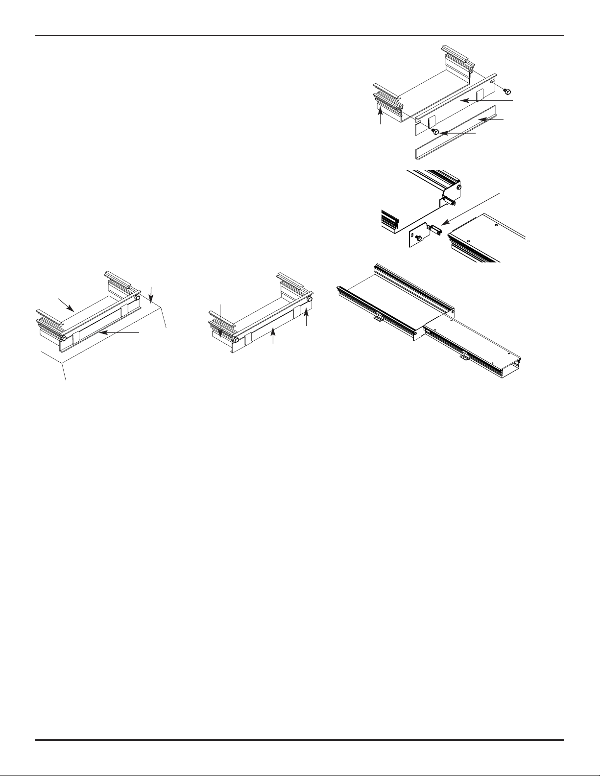
3. End Closure:
A. For full length closure, fasten top part of end closure to
end of trenchduct with two hex head screws provided
(see Figure 1). For partial end closure, fasten closure to
end of wider trenchduct with hex head screws provided
(see Figure 2).
B. Tighten screws into aluminum rail slot until end closure is
secure to trenchduct.
C. For partial closure, slide twin pilot into aluminum rail of
narrow trenchduct and tighten #10-24 hex head screws
(see Figure 2A).
D. Install and adjust bottom part of end closure (maximum 1"
[25mm]) until it is level with bottom of trenchduct.
E. If used on cell or deck, tack weld end closure bottom
flange to top of raceway (see Figure 3).
F. If used on underfloor duct or alone, flip end closure
bottom around so bottom flange is hidden under
trenchduct (see Figure 4).
Top Part
Bottom Part
Trenchduct
Figure 1
Figure 2
Figure 2A
Figure 4
Figure 3
Hex Head Screw
Twin pilot
Top of Raceway
Trenchduct
Tack Weld
Along Here
Bottom Part
(Flip Over)
Top Part
Trenchduct
Page 3

6. Work Subsequent to Trenchduct Installation by Other Contractors:
A. Concrete Placement and Curing:
1. Reinforced concrete design shall be in accordance with American Concrete Institute Specifications for Structural
Concrete for Buildings (ACI301-72) and ACI Building Code Requirements for Reinforced Concrete (ACI318-82),
2. Concrete placement shall follow proper and accepted industry practice and be in accordance with ACI Recommended
Practice for Measuring, Mixing, Transporting, and Placing Concrete (ACI304-73).Concrete must be vibrated at all
trenchducts to insure that the concrete completely fills underneath the system. However, it is imperative that the
concrete not be over vibrated. Over vibration causes segregation of material in the concrete mix which, in turn,
leads to weakening of concrete strength.
3. Concrete curing shall follow proper and accepted industry practice and be in accordance with ACI301-72.
B. After the Concrete Pour:
1. Excess moisture should be removed from inside of the trenchduct within 48 hours after the concrete pour. Remove
cover plates where water may have entered the trenchduct and remove all water from the system. Periodically, check
the trench system for water accumulation or condensation. Depending on job site and weather conditions, a cover
plate removed at several locations along each run will help prevent condensation inside the system. If water is left in
the trench system, it may freeze, causing severe damage to the trench and floor slab.
2. When heavy material or equipment loads will be placed on or moved over the trench system, install temporary planking
that will transfer loads to the adjacent concrete.
NOTE: Cover plates, compartment dividers or other trench components that are damaged during construction must
be replaced by others. This will not be the responsibility of Walker.
3. For BVA Bottomless or IBVA Intermittent Bottomless Trench: Place metal void closures under bottom flange(s)
or on top of outside bottom flange of trench side rail assembly and secure to deck and trench side rail by fillet welds
(1/2" [12.7mm] or longer) and/or blind rivets on 24" [610mm] centers.
4. Floor finish contractor shall clean and prepare cover plates prior to final floor covering installation. Use a suction cup
lifter, Walker part #485, to remove cover plates.
For tile floors: The outside trim extrusion is reversed to the tile position and secured in place
(refer to Finishing Notes and Details).
For carpet floors: The trim extrusion shall remain flush.
5. Consult the carpet supplier for recommendations on installing carpet over the trenchducts.
NOTE: Bottomless trench for use only over UL Listed Cellular Metal Raceway or UL Listed Cellular Metal Floor Raceway
Fluted Section Fittings.
Page 4

Concrete Finishing:
BOTTOMLESS AND FULL BOTTOM VA TRENCH
Figure 1 – Section Thru Trench
Figure 2 – Concrete Finish
Step 3
Depth of Pour
Void Closures as Required –
(Shipped Separately)
Compartments as Required –
(Shipped Separately)
Bottom Required for
Power Cables
Cover Plate as Required
Leveling Screw (Only use when
Adjustments to Screed is Required
and after Trench is Fastened ).
Figure 3 – Tile Finish
Escutcheon
Steps 5 and 6
Step 4
Top of Trenchduct
© Copyright 2006 Wiremold / Legrand All Rights Reserved
Wiremold / Legrand
U.S. and International:
60 Woodlawn Street • West Hartford, CT 06110
1-800-621-0049 • FAX 860-232-2062 • Outside U.S.: 860-233-6251
Canada:
570 Applewood Crescent • Vaughan, Ontario L4K 4B4
1-800-723-5175 • FAX 905-738-9721
IY0072 R2 0406
1. Trench installer shall set top of trenchduct level with concrete screed line. Concrete installer must maintain top of finished
floor level with top of trenchduct.
2. Make all height adjustments prior to concrete pour. If ponding or other problems are encountered before or during the
concrete pour, re-adjustment shall be made as determined by the general contractor in order to maintain a level floor.
3. See Section 6a for Concrete Placement.
4. Concrete installer to hand trowel concrete level with top of trenchduct a minimum of 18" [457mm] along both sides
of trenchduct.
5. If floor is to have 1/8" [3.2mm] thick tile, tile installer shall remove and prepare covers to receive tile. After tile is installed,
drill and countersink covers to fit hold-down screw escutcheons.
6. Just prior to replacing tiled covers, remove trim and install as shown in Figure 3. Interchange outside mitered trim on flat
ells with inside mitered trim. Replace covers and complete balance of floor tile installations.
 Loading...