

LEGRAND Trimod MCS 15, Trimod MCS 3, Trimod MCS 30, Trimod MCS 40, Trimod MCS 60 User Manual
...Page 1

Trimod MCS
User manual
Item LE10960AA-01/19-01 CT
Page 2

Trimod MCS
ENGLISH 3
UK
2
Page 3

Trimod MCS
Contents
1 Introduction 5
1.1 General information 5
1.2 Purpose of the manual 5
1.3 Symbols in the manual 6
1.4 Where and how to keep the manual 6
1.5 Update of the manual 6
1.6 Manufacturer's liability and guarantee 6
1.6.1 Guarantee terms 7
1.6.2 Guarantee extension and maintenance contracts 7
1.7 Copyright 7
2 Regulatory and safety requirements 8
2.1 General notes 8
2.2 Denitions of “Skilled Technician” and “Operator” 8
2.2.1 Skilled Technician 8
2.2.2 Operator 8
2.3 Personal Protective Equipment 9
2.4 Hazard signs in the workplace 9
2.5 Signs on the equipment 9
2.6 General warnings 10
2.7 How to proceed in an emergency 11
2.7.1 First-aid procedures 11
2.7.2 Fire procedures 11
3 Technological description 12
3.1 Trimod MCS technology 12
3.2 Features 14
3.3 Models 16
3.4 Block diagram of interconnections and distributions of the EPS 20
4 Unpacking and positioning 21
4.1 Visual check 21
4.1.1 Equipment and supplied accessories check 21
4.2 Unpacking 21
4.3 Check of the content 21
4.4 Movement 22
4.5 Positioning constraints 22
4.6 Final operations 22
5 Communication devices 23
5.1 RS232 serial ports 23
5.2 Contact interface 24
5.3 Emergency Power O (EPO) 24
5.4 Logic level interface 25
5.5 Network card (SNMP) slot 26
User manual
3
Page 4

Contents
6 Control panel 27
6.1 Description 27
6.2 Service Mode 28
6.3 Main screen 28
6.4 Main menu and submenu 30
6.4.1 UPS Status 31
6.4.2 UPS Setup 33
6.4.3 Power Modules 37
6.4.4 Events 39
6.4.5 Tools 39
6.4.6 Log Out 39
6.5 POWER ON/OFF menu 40
6.6 Switching o the EPS 40
6.7 Switching on the EPS 40
7 Diagnosis 41
7.1 Luminous and audible notications 41
7.2 Messages 43
8 Installation and maintenance 50
8.1 Introduction 50
8.2 Installation 50
8.3 Preventive maintenance 50
8.4 Periodical checks 50
8.5 Ordinary maintenance 50
8.6 Extraordinary maintenance 50
9 Warehousing 51
9.1 EPS 51
9.2 Batteries 51
10 Dismantling 52
10.1 Battery disposal 52
10.2 EPS dismantling 52
10.3 Electronic component dismantling 52
11 Technical data 53
4
Page 5

Trimod MCS
1. Introduction
CAUTION
The instructions in this manual are intended for an OPERATOR (paragraph 2.2.2)
1.1 General information
Congratulations on your LEGRAND TRIMOD MCS EPS purchase.
Thanks to this EPS, your critical equipment will always be protected by a constant and reliable electricity supply.
LEGRAND is specialized in designing and producing EPS. Trimod MCS is unique in its kind: it is modular, redundant and
belongs to the last generation of medium power EPS.
High reliability, low running costs and excellent electrical performance are some of its features. The high quality standard
of LEGRAND in design and production allows Trimod MCS to pass the strictest quality tests.
The EPS has been designed in compliance with the existing European Union directives, with the technical standards that
include their requirements and with the eco-design guidelines.
The equipment is produced at an ISO14001 certified factory.
This publication, simply defined “user manual” herein, contains all the information for the use of the Trimod MCS EPS, also
referred to as “equipment” in this manual.
User manual
The contents of the user manual are intended mainly for an operator (see paragraph 2.2.2) or for people, generically defined as “users”, who have the need and/or obligation to provide instructions or work directly on the equipment for their
assigned tasks.
These people can be the following:
- managers;
- heads of operating areas;
- department heads;
- direct private users.
The original text of this publication, drafted in Italian, is the only reference for the resolution of disputes of interpretation
linked to translations into other languages.
1.2 Purpose of the manual
The purpose of this manual is to provide the operator with instructions for safely using the equipment after the installation performed by a skilled technician.
Any adjustments and extraordinary maintenance operations are not dealt with in this manual because they are the sole
preserve of the LEGRAND Technical Support Service.
The reading of this manual is essential but does not substitute the skill of the technician who must have received adequate preliminary training.
The intended use and configurations envisaged for the equipment and shown in this manual are the only ones allowed
by the Manufacturer.
Any other use or configuration must be previously agreed with the Manufacturer in writing and, in this case, the written
agreement will be attached to the installation and user manual.
This manual also makes reference to laws, directives and standards that the operator is required to be aware of and consult.
5
Page 6

1. Introduction
1.3 Symbols in the manual
Some operations are shown in graphic symbols that draw the attention of the reader to the danger or the importance
they imply:
DANGER
This indication shows a danger entailing a high degree of risk that, if not avoided, will lead to death or serious injury or
considerable damage to the equipment and the things around it.
WARNING
This indication shows a danger entailing a medium degree of risk that, if not avoided, could lead to death or serious injury
or considerable damage to the equipment and the things around it.
CAUTION
This indication shows a danger entailing a low level of risk that, if not avoided, could lead to minor or moderate injury or
material damage to the equipment and the things around it.
INDICATION
This symbol indicates important information which should be read carefully.
1.4 Where and how to keep the manual
This manual must be kept in a safe, dry place and must always be available for consultation.
It is recommended to make a copy of it and file it away.
If information is exchanged with the Manufacturer or the authorised assistance personnel, it is essential to refer to the
equipment’s rating plate data and serial number.
INDICATION
The supplied manuals are an integral part of the equipment and must therefore be kept for their entire lifetime.
In case of need (for example in case of damage that even partially compromise the consultation) the operator is required
to get a new copy from the Manufacturer, quoting the publication code on the cover.
1.5 Update of the manual
The manual reflects the state of the art when the equipment was put onto the market. The publication conforms with the
directives current on that date. The manual cannot be considered inadequate when new standards come into force or
modifications are made to the equipment.
Any addition the Manufacturer considers appropriate to send to the users, must be kept together with the manual of
which they will become an integral part.
The updated version of the manual is available on the Internet at http://www.ups.legrand.com
1.6 Manufacturer's liability and guarantee
The skilled technician and the operator shall scrupulously comply with the precautions indicated in the manuals. In particular they must:
- always work within the operating limits of the equipment;
- always carry out constant and careful maintenance through a skilled technician who complies with all the procedures
indicated in the installation and maintenance manual.
The Manufacturer declines all indirect or direct responsibility arising from:
- installation and wiring completed by personnel not possessing the qualifications required by the regulations of the
country of installation for working on equipment operating on dangerous voltages;
- installation and wiring completed by personnel not wearing the Personal Protective Equipment required by the regulations of the country of installation;
- failure to observe the installation, maintenance instructions and use of the equipment which differs from the specifications in the user manual;
- use by personnel who have not read and thoroughly understood the content of the user manual;
- use that does not comply with the specific standards used in the country where the equipment is installed;
- modifications made to the equipment, software, operating logic unless they have been authorised by the Manufacturer
in writing;
6
Page 7

Trimod MCS
- repairs that have not been authorised by the LEGRAND Technical Support Service;
- damage caused intentionally, through negligence, by acts of God, natural phenomena, fire or liquid infiltration.
- damage caused by the use of batteries or protections other than those indicated in the installation and maintenance
manual;
- damage caused by failure to install or establish the safety protections indicated in the manuals, or by failure to comply
with the safety labels.
Transfer of the equipment to others also requires the handing over of all the manuals. Failure to hand over the manuals
shall automatically nullify any right of the buyer, including the terms of the guarantee where applicable.
If the equipment is sold to another party in a country where a dierent language is spoken, the original owner shall be
responsible for providing a faithful translation of the manuals in the language of the country where the equipment will
be used.
1.6.1 Guarantee terms
The terms of the guarantee may vary depending on the country where the EPS is sold. Check the validity and duration
with LEGRAND's local sale representative.
If there should be a fault in the equipment, contact the LEGRAND Technical Support Service which will provide all the
instructions on what to do.
Do not send anything back without LEGRAND's prior authorization.
User manual
The guarantee becomes void if the EPS has not been brought into service by a properly trained skilled technician
(see paragraph 2.2.1).
If during the guarantee period the EPS does not conform with the characteristics and performance laid down in this manual, LEGRAND at its discretion will repair or replace the EPS and relative parts.
All the repaired or replaced parts will remain LEGRAND's property.
LEGRAND is not responsible for costs such as:
- losses of profits or earnings;
- losses of equipment, data or software;
- claims by third parties;
- any damage to persons or things due to improper use, unauthorized technical alterations or modifications;
- any damage to persons or things due to installations where the full compliance with the standard regulating the specific
usage applications have not been guaranteed.
1.6.2 Guarantee extension and maintenance contracts
The standard guarantee can be consolidated in an extension contract (maintenance contract).
Once the guarantee period has passed, LEGRAND is available for giving a technical assistance service able to meet all
requirements, maintenance agreements, 24/7 availability and monitoring.
For more information contact the LEGRAND Technical Support Service.
1.7 Copyright
The information contained in this manual cannot be disclosed to any third party. Any partial or total duplication of the
manual by photocopying or other systems, including electronic scanning, which is not authorised in writing by the Manufacturer, violates copyright conditions and may lead to prosecution.
LEGRAND reserves the copyright of this publication and prohibits its reproduction wholly or in part without previous written authorisation.
7
Page 8

2. Regulatory and safety requirements
DANGER
Before carrying out any operation on the equipment, it is necessary to read the entire manual carefully, especially
this chapter.
Look after this manual carefully and consult it repeatedly while using the EPS.
2.1 General notes
The equipment has been made for the applications given in the manuals. It may not be used for purposes other than
those for which it has been designed, or differently from those specified.
2.2 Definitions of “Skilled Technician” and “Operator”
2.2.1 Skilled Technician
The professional figure who will carry out the installation, start up and ordinary maintenance is called "Skilled Technician".
This definition refers to people who have specific technical qualification and are aware of the method of installing, assembling, repairing, commissioning and safe use of the equipment.
In addition to the requirements listed in the paragraph below for general operators, the Skilled Technician must be qualified in accordance with the safety regulations in force in the country of installation on the measures to implement when
working in presence of hazardous voltage. He must also use the Personal Protective Equipment required by the safety
regulations in force at the country of installation for all the activities indicated in the installation and maintenance manual
(see paragraph 2.3)
WARNING
The safety manager is responsible for protection and company risks prevention according to what is indicated in the
European directives 2007/30/EC and 89/391/EEC regarding safety in the workplace.
The safety manager must ensure that all the people working on the equipment have received all the instructions included
in the manuals with particular reference to those contained in this chapter.
2.2.2 Operator
The professional figure assigned to the equipment for normal use is called "Operator".
This definition refers to people who know how to operate the equipment as described in the user manual and have the
following requisites:
1. technical education, which enables them to operate according to safety standards in relation to the dangers linked to
the presence of electric current;
2. training on the use of Personal Protective Equipment and basic first aid interventions.
The company safety manager in choosing the person (operator) who uses the equipment, must consider:
- the person’s work fitness according to the laws in force;
- the physical aspect (not disabled in any way);
- the psychological aspect (mental stability, sense of responsibility);
- the educational background, training and experience;
- the knowledge of the standards, regulations and measures for accident prevention.
He should also impart training in such a way as to provide thorough knowledge of the equipment and its component
parts.
The operator shall consult the user manual at any time. He shall also follow the requirements provided to achieve maximum safety for himself and others during all operating phases.
Some typical activities the operator is expected to carry out are:
- the use of the equipment in its normal operating status and the restore of the functioning after it shuts down;
- the activation of the necessary provisions for maintaining the quality performance of the EPS;
- the cleaning of the equipment;
- cooperation with personnel responsible for ordinary maintenance activities (skilled technicians).
8
Page 9
Trimod MCS
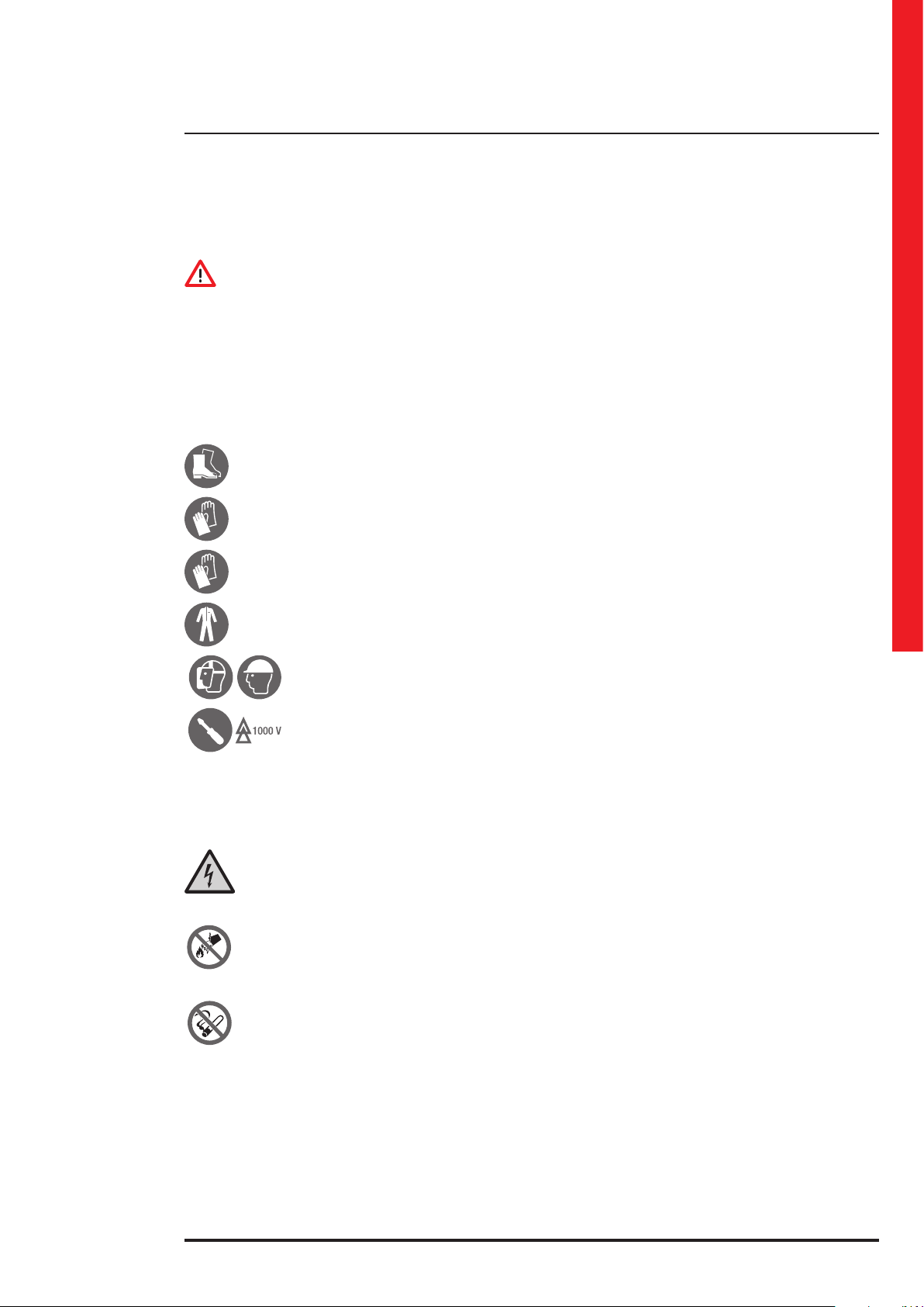
2.3 Personal Protective Equipment
DANGER
The equipment poses a considerable risk of electric shock and a high short circuit current. During use and maintenance
operations, it is forbidden to operate without the equipment listed in this paragraph.
People responsible for operating this equipment and/or passing close to it must not wear garments with flowing sleeves,
nor laces, belts, bracelets or other metal pieces that might cause a danger.
The following signs sum up the minimum Personal Protective Equipment to wear at all times.
Additional requirements may be pro vided for by the safety regulations in force in the country of installation.
Anti-accident and no-spark shoes
with rubber sole and reinforced toe
Safety gloves for protection from mechanical risks
User manual
Dielectric gloves for protection from dangerous
voltages
Protective clothing for electrical work
Electrical protection helmet and visor
Insulated tools
2.4 Hazard signs in the workplace
The following signs must be exhibited at all points of access to the room where the equipment is installed:
Electric current
This sign indicates the presence of electrical live parts.
How to proceed in an emergency
Do not use water to quench res but just the extinguishers specically designed for putting out res in electrical
equipment.
No smoking
This sign indicates that smoking is not allowed.
2.5 Signs on the equipment
Displayed on the equipment are explanatory plates that can vary depending on the country the equipment is intended
for and constructional standards applied.
Make sure the instructions are adhered to. It is strictly prohibited to remove these plates and to work in a way that differs
from what is written there.
The plates must always be clearly read and they must be cleaned periodically.
If a plate deteriorates and/or it is no longer legible, even partially, the Manufacturer must be contacted for another one
in order to replace it.
9
Page 10

2. Regulatory and safety requirements
CAUTION
The plates must not be removed or covered. No other plates may be affixed to the equipment without the Manufacturer's
prior written authorisation.
WARNING
Potential risks can be drastically reduced by wearing the Personal Protective Equipment listed in this chapter. These protections are indispensable. Always operate with due care around dangerous areas marked by the appropriate warning
signs on the equipment.
2.6 General warnings
DANGER
The EPS works with dangerous voltages. Only SKILLED TECHNICIANS must perform the installation and ordinary
maintenance operations. No part of the EPS can be repaired by the operator.
Extraordinary maintenance operations must be carried out by LEGRAND Technical Support Service personnel.
WARNING
A battery can present a risk of electrical shock and high short circuit current. The following precautions should be observed when working on batteries:
a) remove watches, rings or other metal objects;
b) use tools with insulated handles;
c) wear rubber gloves and boots;
d) do not lay tools or metal parts on top of batteries;
e) disconnect the charging source prior to connecting or disconnecting battery terminals;
f ) determine if battery is inadvertently grounded. If inadvertently grounded, remove source from ground. Contact with
any part of a grounded battery can result in electrical shock. The likelihood of such shock can be reduced if the ground
connections are removed during installation and maintenance (applicable to remote equipment and battery supplies
without a grounded supply circuit).
g) never leave powered cables uncovered.
Do not dispose of batteries in a fire. The batteries may explode.
Do not open or mutilate batteries. Released electrolyte is harmful to the skin and eyes.
The batteries installed inside the cabinet must be disposed of correctly. For the disposal requirements refer to local laws
and relevant standards.
CAUTION
The EPS works with TT and TN systems. It has a pass-through neutral architecture: the status of the output neutral is
the same as the input neutral.
When the output load needs a different neutral status from the input status, it is necessary to place downstream of the
EPS a suitably scaled isolation transformer protected in compliance with the standards in force.
CAUTION
Do not open the battery fuse holders while the EPS is powering the loads in battery mode.
WARNING
To reduce the risk of fire or electric shock, the EPS must work in clean and indoor environments with controlled temperature and humidity. It must be kept away from inflammable liquids and corrosive substances. The room temperature must
not be above +40°C (+104°F) and the relative humidity must be a maximum of 95% not condensing.
10
Page 11

Trimod MCS
CAUTION
The equipment generates, uses and can radiate radio frequency energy. If it is not installed and used in accordance with
the instructions in the manuals, it may cause harmful interference with radio communications.
Trimod MCS 3,5,7 and 10 are category C2 products according to standard EN62040-2.
In the home environment these devices could cause radio interference; in this case appropriate countermeasures must
be taken.
All other Trimod MCS models are category C3 products according to standard EN62040-2.
They can therefore be used in commercial and industrial environments; nevertheless restrictions or adequate countermeasures might be necessary to avoid radio interference.
CAUTION
- The equipment must be maintained and used according to the instructions written in the manuals
- The departmental manager must instruct the operating and maintenance personnel on the safe use and maintenance
of the equipment.
- Only specifically-trained, highly skilled personnel are allowed access to the equipment order to perform maintenance.
While the maintenance operation is being carried out, signs saying "Maintenance work in progress" must be affixed in
the department in such a way that they can be easily seen from each and any access area.
- Any intervention on the equipment must be done only after it has been disconnected from the power supply network
by means of a switch disconnector and must be locked with an appropriate padlock.
- The EPS must not be turned on if liquid is leaking from the batteries.
- Depositing flammable material near the equipment is strictly forbidden. The equipment should always be locked, and
only specifically trained personnel are allowed access to them.
- Do not disable any safety, signalling or warning devices and do not ignore any alarms, warning messages or notices, no
matter whether they are generated automatically or represented by plates fixed to the equipment.
- Do not run the equipment with fixed protections not installed (panels etc.).
- In case of breaking, buckling or malfunctioning of the equipment or parts of it, repair or replace immediately.
- For no reason can the equipment, the devices and the operation sequence, be modified, disabled or tampered with in
any way, without prior consultation with the Manufacturer.
- When replacing fuses, only use ones of the same type.
- The replacement of the batteries is an operation intended to be carried out by a skilled technician.
- Keep a register in which to enter the date, time, type, performer’s name and any other useful information about each and
any routine- and extraordinary-maintenance operation.
- Do not use oils or chemical products for cleaning because they could scratch, corrode or damage certain parts of the
equipment.
- The equipment and workplace must be kept completely clean.
- Upon completion of the maintenance operations, before connecting the power supply, carry out a careful check in order
to make sure that no tools and/or material of any kind have been left next to the equipment.
User manual
CAUTION
The skilled technician must not leave at the disposal of the operator:
- the keys for opening the EPS door;
- the installation and maintenance manual.
2.7 How to proceed in an emergency
The following information are general.
For the specific interventions consult the regulations in force in the country where the equipment is installed.
2.7.1 First-aid procedures
When administering first aid, adhere to the company rules and the usual procedures.
2.7.2 Fire procedures
Do not use water to quench fires but just the extinguishers specifically designed for putting out fires in electrical equipment.
11
Page 12

3. Technological description
3.1 Trimod MCS technology
LEGRAND® has developed an innovative project that is the only one of its kind by producing Trimod MCS, the EPS with 3,
5, 7, 10, 15, 20, 30, 40, 60 and 80 kVA power.
The concepts underlying the project are modularity, expandability and redundancy in such a way as to offer maximum
reliability and to be the guarantee of considerable savings.
Trimod MCS is EPS designed in accordance with EN 50171 for the preservation of power supply in emergency and security
systems. Some of its features are:
- permanent overload capability of 120% in relation to the rated power;
- batteries with rated life expectancy of 10 years;
- battery polarity inversion protection
- protection against complete discharge;
- short circuit protection;
- high current battery charger for full charge time of 12 hours;
- IP20 metal enclosure according to EN 60598-1.
If the mains is available, the EPS output is enabled by default. It is possible to change this setting from the control panel.
If the mains input is missing, the output is supplied by the EPS in battery mode.
Trimod MCS is a modular EPS whose base module is single phase and can be programmed to obtain the desired input/
output configuration. It is thus possible to manage three phase and single phase voltages on input and output to have a
choice of the traditional three phase/three phase, three phase/single phase, single phase/three phase and single phase/
single phase. At the same time it is possible to obtain simultaneously single phase and three phase lines on output or two
or more single phase lines even with different power.
For every configuration it is possible to have redundancy that is both complete and partial. For example, one normal three
phase (or redundant) line can coexist with a redundant single phase (or normal) line on output.
The philosophy underlying modularity has also been applied to the batteries that have been supplied in individual drawers that can be extracted and make installation and maintenance easier.
The EPS is controlled by one command board.
The command board (CM) and the power modules (PM) are identified by a unique address inside the system, as shown below:
CM 0 PM 0 PM 1 PM 2
12
Trimod MCS 3-5-10 Trimod MCS 20 Trimod MCS 7-15
Page 13
CM 0 PM 0 PM 1 PM 2
PM 3 PM 4 PM 5
Trimod MCS
User manual
Trimod MCS 30 Trimod MCS 40
CM 0 PM 0 PM 1 PM 2
PM 3 PM 4 PM 5
PM 6 PM 7 PM 8
CM 0 PM 0 PM 1 PM 2
PM 3 PM 4 PM 5
PM 6 PM 7 PM 8
PM 10 PM 11
PM 9
Trimod MCS 60
Trimod MCS 80
13
Page 14

3. Technological description
The command board is connected to a control panel with display from which it is possible to verify the status and setups
of the EPS and to a communication interface with RS-232 and SNMP connection, dry contacts and logical contacts. It is
possible to access all the EPS functions from the control panel and communicate through any of the interfaces present
thereby guaranteeing the redundancy of the peripherals as well. In installations with three separate single phase line on
output, it is possible to manage each line independently through the software. For example, it is possible to prioritise the
autonomy of one of them during battery operation. A bypass input line separated from that of the mains input makes it
possible to supply the bypass with a second power source (the neutral wires of the two lines must be in common).
The technology used in the hardware and the firmware of the EPS represents the current state of the art.
A sophisticated microprocessor-type control optimises the performance both on the Booster/PFC side and on the output inverter. The recharge curve of the battery has been designed to get the maximum useful life and have the greatest
autonomy possible if the main power goes off. The electronic boards are entirely assembled on LEGRAND automated
lines and tested to the highest quality standards. Every device goes through an extended period of operation at full load
before being sent to the customer.
3.2 Features
Modular-redundant architecture
The modular-redundant architecture is the best solution for protecting the nerve centres of a company and has the following advantages:
- there is one control of the devices supplied;
- modular expandability;
- module redundancy;
- easy maintenance;
- low running cost;
- compactness.
Efficiency
Trimod MCS concentrates particularly on both the energy absorbed from the mains and the energy provided to the load.
They are characterised by high efficiency (up to 96%), PF on input>0,99, THDi <3%.
The advantages of a high efficiency are:
- reduction of the power absorbed from the EPS but not supplied to the load and transmitted to the environment as heat;
- less heat loss transmitted to the environment means reducing the need for ventilation or air conditioning systems in the
installation site;
- no power factor correction cost and so no increase in charges;
- no need to increase the size of any generator upstream of the EPS.
Expandability
Most EPS systems on the market are of the non-modular and non-expandable type thus requiring an initial upscaling of
the system to make future expansions possible.
The advantages of an expandable system are:
- optimisation of investments for EPS, making them adequate for the current requirements without precluding future
expansions and avoiding wastes of energy;
- increase in the efficiency of the system thanks to proper sizing.
Reliability
To obtain a level of redundancy with traditional EPS, it is necessary to put at least two in parallel thereby doubling the
power acquired, the space occupied and the electricity consumed. Trimod MCS modular architecture makes it possible to
have redundant configurations within a single cabinet.
The advantages are:
- a redundant modularity EPS can be configured as a power redundant N+X system. Even in the case of a fault in a
module, the equipment continues to function avoiding any downtime;
- clear indications and a large display make it possible to find the fault more quickly;
- the modular architecture makes it possible to speed up the solution to problems through the simple replacement of the
faulty module without interrupting the service;
- high percentage of faults resolved at the first attempt.
Power module
The high-efficiency single phase module, available in three power sizes of 3400 VA (PM4), 5000 VA (PM6) and 6700 VA
(PM7) respectively, and is mainly made up of the following functional blocks:
- command and control logic (managed by a microprocessor);
- PFC rectifier/booster;
- inverter;
- battery charger;
- automatic bypass.
In each power module there is a microcontroller that can oversee the main functions of the individual unit, monitor its
correct operation and flag up any malfunctions.
The power module is Plug & Play to make the power expansion and any maintenance operation easier. Every module is
put in parallel with other identical ones until reaching the power of the EPS.
The modules are independent of each other and can function even if there is a fault in one of them. At the front of the
module there is a multicoloured LED with traffic-light code green-yellow-red, making it possible to identify the operating
status of the electronic unit quickly.
14
Page 15

The power modules are housed on shelves also called “tunnels” that can house three modules.
The block diagram of the power module is the following:
Trimod MCS
User manual
Batteries
The battery modules are designed for easy insertion into the dedicated cabinet and they do not need any operation for
their connection. A drawer consists of five 12V-9Ah batteries, connected in series and thanks to the Plug & Play connection it is easy to extract and insert it in the cabinet.
The nominal battery voltage for the Trimod MCS is 240Vdc, therefore a complete branch consists of four battery drawers
(for a total of twenty 12Vdc batteries) that form what is called KB (Battery Kit).
In order to ensure the maximum level of safety, the voltage of each drawer is properly isolated into two branches of 24 V
and 36 V and it is only restored when the drawer is completely inserted into its housing.
This allows conformity with the standard EN 62040-1 on electrical safety that requires the use of adequate protection and
particular care when handling dangerous voltages above 50 Vdc where direct contact is possible.
The battery operation autonomy of the EPS can be increased by adding more battery drawers in multiples of four, using
both the seats in the EPS cabinet if available, and the seats in the additional modular battery cabinets.
Digital display and alarm display
Trimod MCS is managed by a microprocessor-type command board (according to the version) and it has a backlit LCD
alphanumeric display with twenty characters on four lines.
The display is incorporated in the control panel where there is also a high-brightness operating status indicator with
traffic light type green-yellow-red.
Five keys situated near the display enable the user to display the operating data, set the operating parameters, analyse
the status of the individual power modules, select the language in which the messages are to be displayed and carry out
a guided set of functional tests and procedures.
BCM - Battery Charger Module 3 108 51
The additional battery charger module works in parallel and in sync with the battery chargers in the power modules and
it is managed by the same algorithm that governs the recharging cycle. Every additional battery charger module provides
up to 15A of charge current that are added to the current of the battery chargers inside the power modules. Every power
module can provide up to 2.5A of charge current. This guarantees a reduction of the charge time in installations requiring
long autonomies and increases the availability of the UPS after a black out. During operation, the module takes current
from the input phase where it is installed.
It is possible to install any quantity of BCMs as long as there is at least one power module and enough empty slots inside
the EPS cabinet. All the information regarding the operating status of the BCM is given by the LED on the front of the
module and by what is shown on the EPS display.
The module is managed by a microprocessor to optimize performance and reliability. It is recommended to install it together with a battery cabinet with capacity exceeding 60 Ah.
ECO MODE
One functioning mode of Trimod MCS is called “eco mode”. With this mode it is possible to save energy while guaranteeing uninterruptability of the power supply to the load connected. During the functioning in eco mode, the load
is powered directly from the electrical mains through the automatic bypass circuit inside the power modules. This
means that the output voltage and frequency are the same as the mains. The advantage obtained in the eco mode is
a greater electrical efficiency and consequently a reduction in consumption. If the output voltage leaves the window
of tolerance (-20% / +15% of the voltage set on the output), the EPS actuates its inverter stage and powers the load
with the energy stored in the batteries. The autonomy during the battery operation depends on the configuration of
the UPS (nominal power, battery capacity) and on the percentage of load applied. When the mains are back within the
tolerance values, the EPS switches automatically back to the eco mode. It is possible to change the operating mode
between on-line and eco mode (and viceversa) both with the EPS on and with the UPS off (in this case entering the
Service Mode).
15
Page 16
3. Technological description
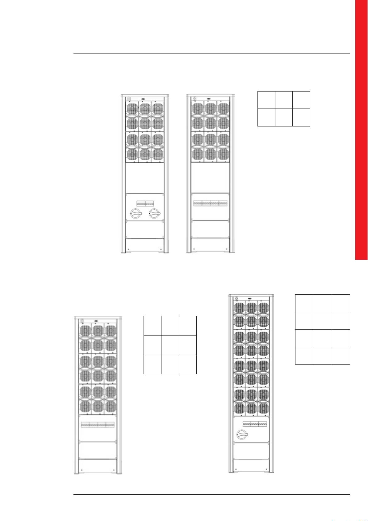
3.3 Models
16
Trimod MCS 3-5-10 Trimod MCS 7-15
Page 17
Trimod MCS
User manual
Trimod MCS 30Trimod MCS 20
17
Page 18
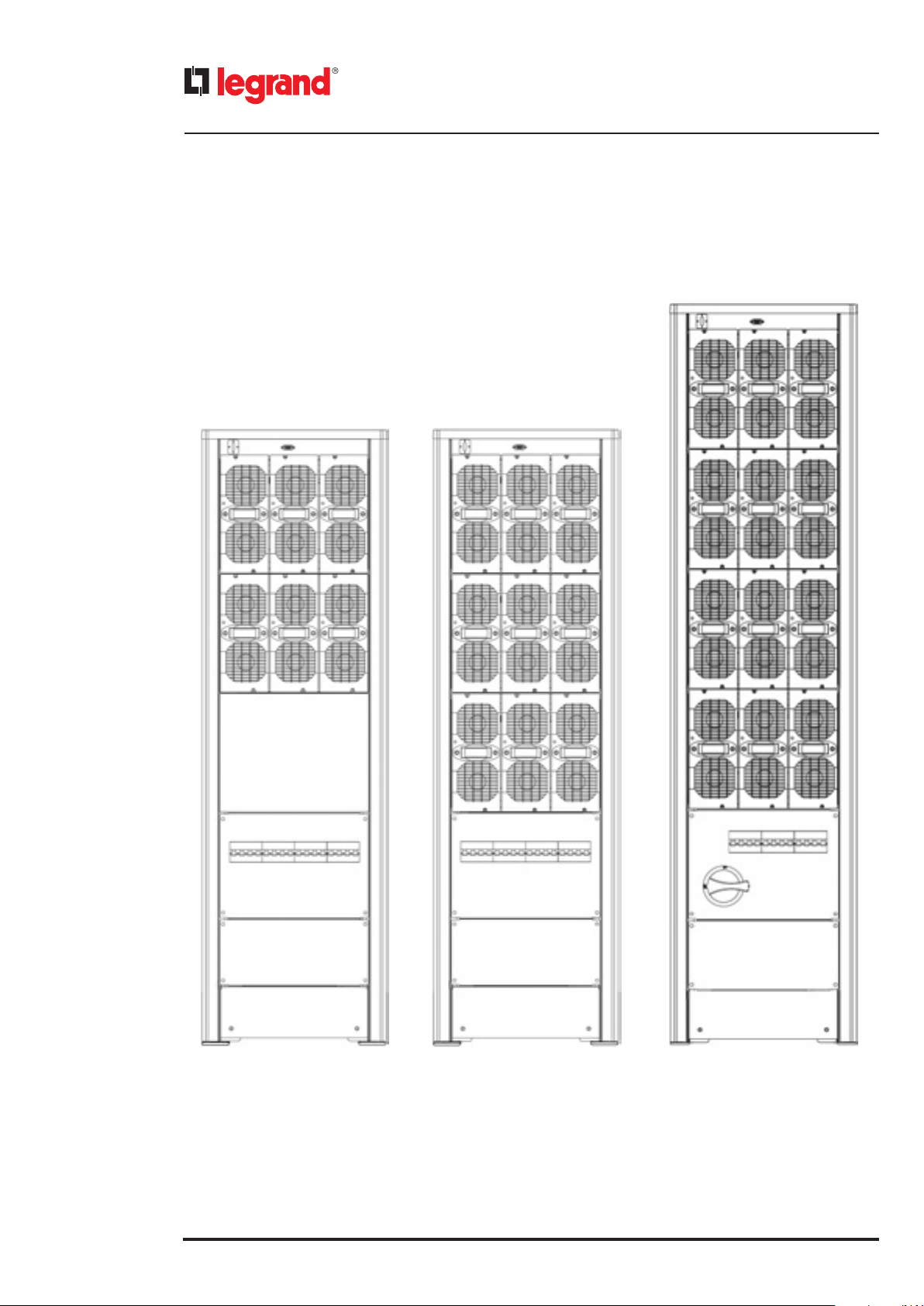
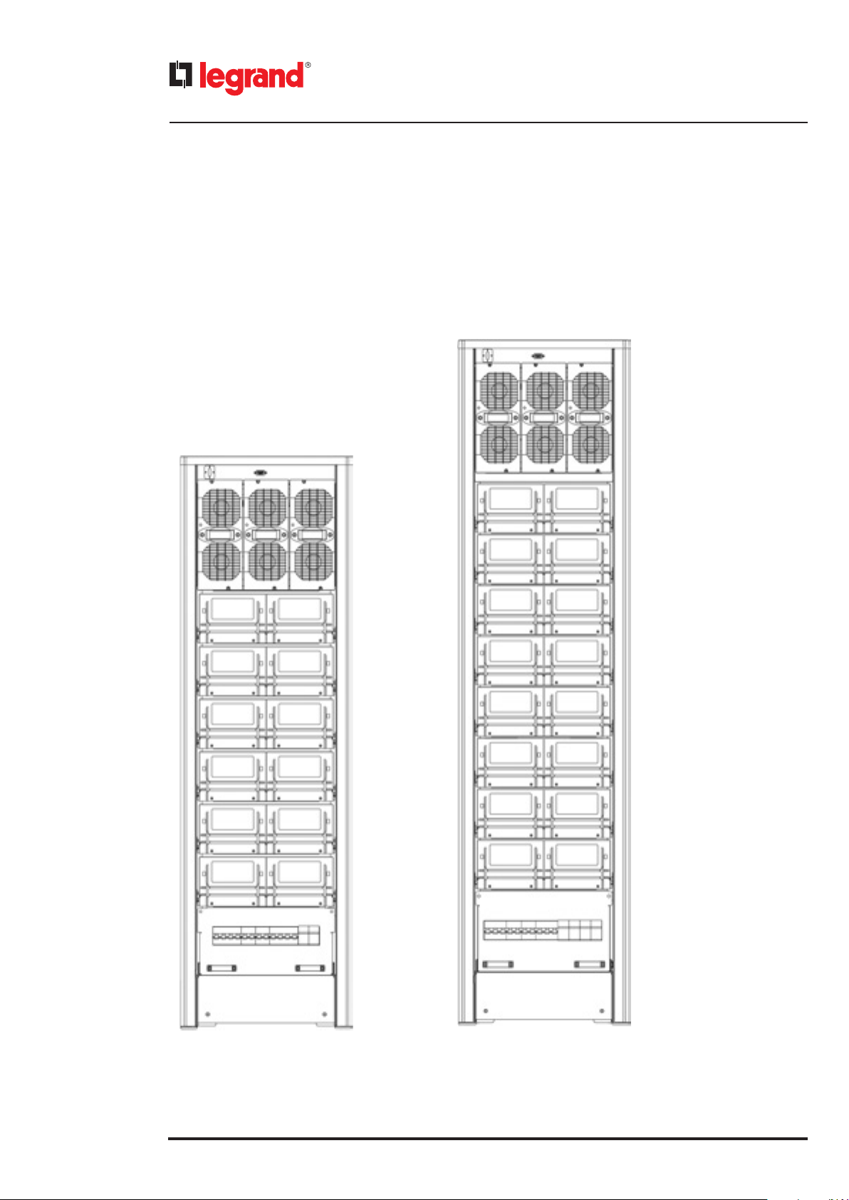
3. Technological description
18
Trimod MCS 40 Trimod MCS 60 Trimod MCS 80
Page 19
Trimod MCS
User manual
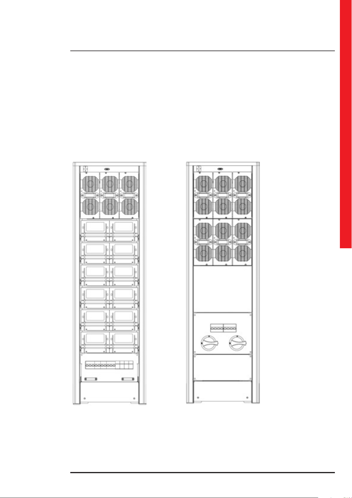
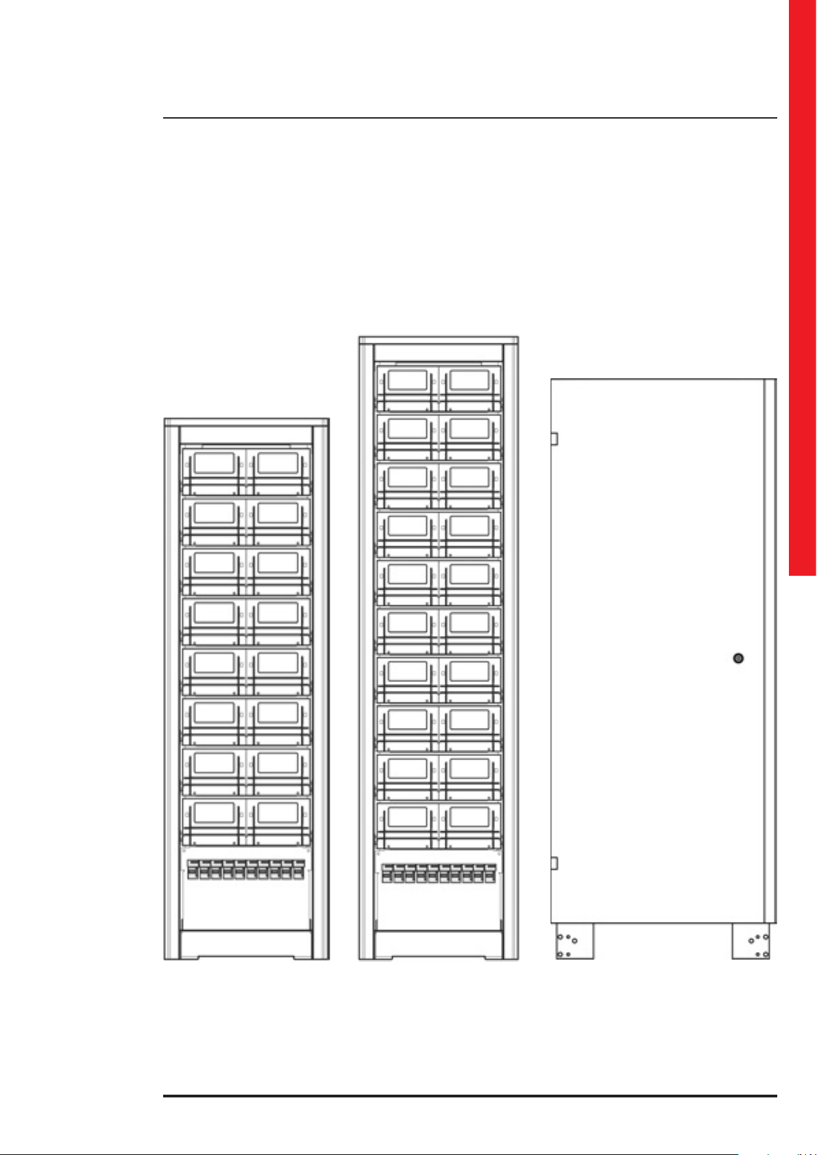
Trimod MCS MODULAR
BATTERY 4KB
(16 battery drawers)
Trimod MCS MODULAR
BATTERY 5KB
(20 battery drawers)
Trimod NON-MODULAR
BATTERY 1KB
(94Ah)
19
Page 20
3. Technological description
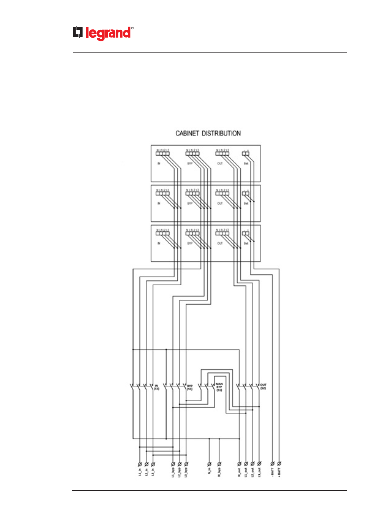
3.4 Block diagram of interconnections and distributions of the EPS
The following figure shows the block diagram of a Trimod MCS 60 distribution. The layout is similar for all the other models.
The bypass input terminals are represented according to the factory configuration (bypass input line in common).
20
Page 21
Trimod MCS
4. Unpacking and positioning
4.1 Visual check
On delivery of the EPS, carefully inspect the packaging and the product for any damage that might have occurred during
transport. Check there is no damage to the indicator on the outer label reading "Shock Watch".
If there is possible or ascertained damaged immediately inform:
- the transporter;
- the LEGRAND Technical Support Service.
Check the equipment corresponds with the material indicated in the delivery documentation.
Follow the instructions in Chapter 9 when storing the equipment.
4.1.1 Equipment and supplied accessories check
The equipment and the relative supplied accessories must be in a perfect state of repair.
Check that:
- the shipping data (address of the recipient, no. of packages, order no, etc.) correspond to what is contained in the deliv-
ery documentation;
- the technical rating plate data on the label applied to the EPS correspond with the material purchased, described in the
delivery documentation;
- the documentation accompanying the equipment includes the installation manual and the user manual.
In case of discrepancy, immediately inform the LEGRAND Technical Support Service before commissioning the equipment.
User manual
4.2 Unpacking
To remove the packaging material, comply with the icons on the outside of the box and observe the following procedure:
1. cut the wrapping material and open the plastic packaging safety holds;
2. open the top of the box;
3. remove the upper protection;
4. remove the four protective corners;
5. remove the packaging container pulling it upwards;
6. remove the pallet and the front/rear bracket from the EPS by undoing the four fixing
screws present;
7. check the equipment for damage. Immediately inform the shipper and the supplier
in the case of apparent damage.
Keep the packaging material for any future shipment of the equipment.
The package can be fully recycled.
4.3 Check of the content
The content of the supply is subject to thorough checking before the shipment. Nonetheless it is always advisable to
check that it is complete and in order on receiving the material.
The following list is general:
- 1 Trimod MCS EPS;
- 1 envelope of accessories containing washers for the contact with the earthing, set of screws for fitting the panels, two
eight-pole terminal strips, a serial cable and fuses (the latter are only included in models with internal batteries);
- 1 envelope of accessories containing one or more EC15 connectors according to the model and connecting jumpers for
the terminal strip (ONLY for Trimod MCS 10, 15, 20 and 30);
- 1 front closing panel;
- 2 base strips for side closing;
- user manual;
- acceptance report;
- installation and maintenance manual.
Should there be defects and/or missing material, immediately inform the LEGRAND Technical Support Service before
commissioning the equipment.
CAUTION
The installation manual must be used and consulted only by SKILLED TECHNICIANS.
INDICATION
In case of purchase of empty cabinets, the power modules and any battery drawers to install must be bought separately.
21
Page 22
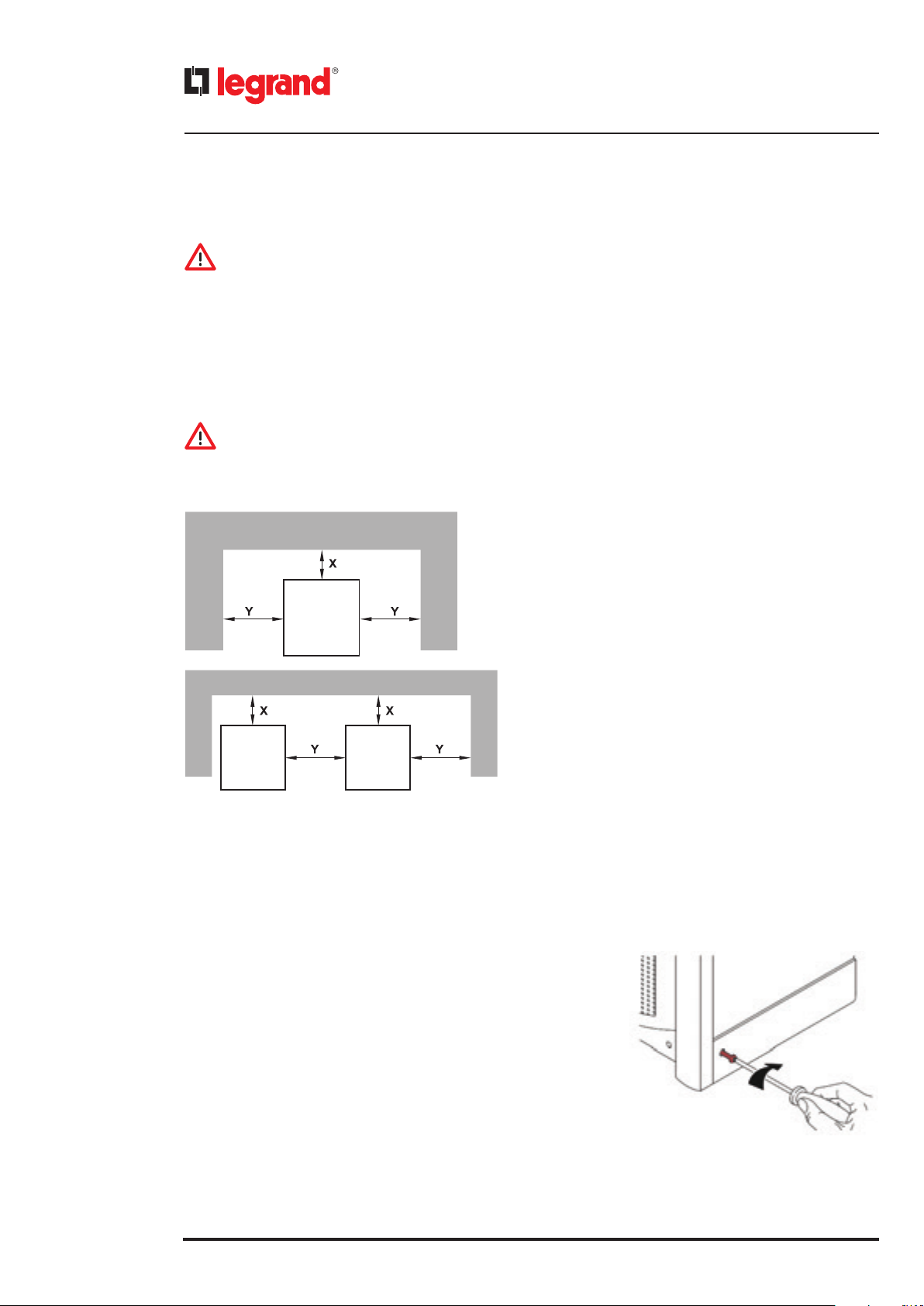
Minimum
recommended
distances for the EPS
X=100 mm /
Y=200 mm
Minimum
recommended
distances Trimod
MCS UPS + Trimod
MCS BATTERY
X=100 mm /
Y=200 mm
4. Unpacking and positioning
4.4 Movement
WARNING
Move the EPS very carefully, lifting it as little as possible and avoiding dangerous swings or falls.
The equipment must always be handled by trained and instructed personnel equipped with the Personal Protective
Equipment illustrated in chapter 2.
The EPS has wheels at the back of the cabinet. Before installations, and while it is still empty, it can be moved by hand by
at least two people.
For any lifting, use a forklift or a transpallet with an adequate carrying capacity, placing the forks in the wooden base and
making sure they come out the other side by at least twenty centimetres.
WARNING
Do not move the equipment after installation or following the insertion of power modules and any battery drawers.
4.5 Positioning constraints
The EPS must be positioned respecting the following conditions:
- temperature and humidity must be within permitted limits;
- fire regulations must be respected;
- the wiring must be simply made;
- front and rear accessibility must be available for assistance or
MCS
BATTERY
CABINET
To safeguard the batteries as well as possible it is necessary to bear in mind that their average lifetime is strongly influenced by the operating room temperature.
Position the equipment in an environment with a temperature range between +20°C (+68°F) and +25°C (+77°F) to guarantee the optimum life of the batteries.
MCS
periodic servicing;
- the cooling flow of air must be guaranteed;
- the air conditioning system must be adequately scaled;
- dust or corrosive/explosive gasses must be absent;
- the premises must be free of vibration;
- the rear and side space must be enough to guarantee an adequate circulation of air for cooling;
- the support surface must be scaled in for the carrying capacity
necessary to support the equipment.
22
Before proceding with the installation operations, make sure that there is enough lighting to clearly see every detail.
Provide artificial lighting if the natural lighting does not satisfy the requirements cited.
In the case of maintenance operations in places that are not sufficiently well lit, portable lighting systems must be used.
4.6 Final operations
Once the EPS has been properly positioned, fit the two base strips and the
front one provided in the accessory kit.
Page 23
Trimod MCS
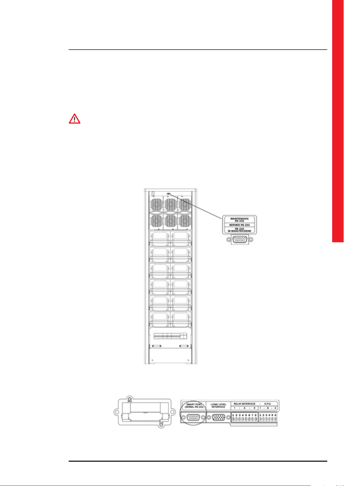
5. Communication devices
Trimod MCS EPS have two RS232 serial ports, one contact interface, one logic level interface on DB15 socket and one
SNMP slot.
The communication interfaces are found in the rear of the equipment. The RS232 serial maintenance port is inside the EPS
door, above the first row of power modules.
CAUTION
For the operator's safety it is essential the interfaces are connected in such a way that:
- the maximum voltage between any two wires connected to the interface and between any one of these wires and the
earth is less than 42Vpk or less than 60Vdc;
- the insulation voltage between any wire connected to the interface and the earth is at least 1500Vac.
5.1 RS232 serial ports
The first of the two RS232 serial ports is called “maintenance RS232” and is found above the first row of power modules,
in a part accessible only to a skilled technician with a key to open the door. The RS232 maintenance door is dedicated
exclusively to diagnostic functions and to update the equipment firmware.
User manual
The second serial port called “user interface” is located at the back of the EPS. Via computer, this port allows to access some
data relative to the operation of the device as well as control the unmanned shutting down of the operating system.
23
Page 24
5. Communication devices
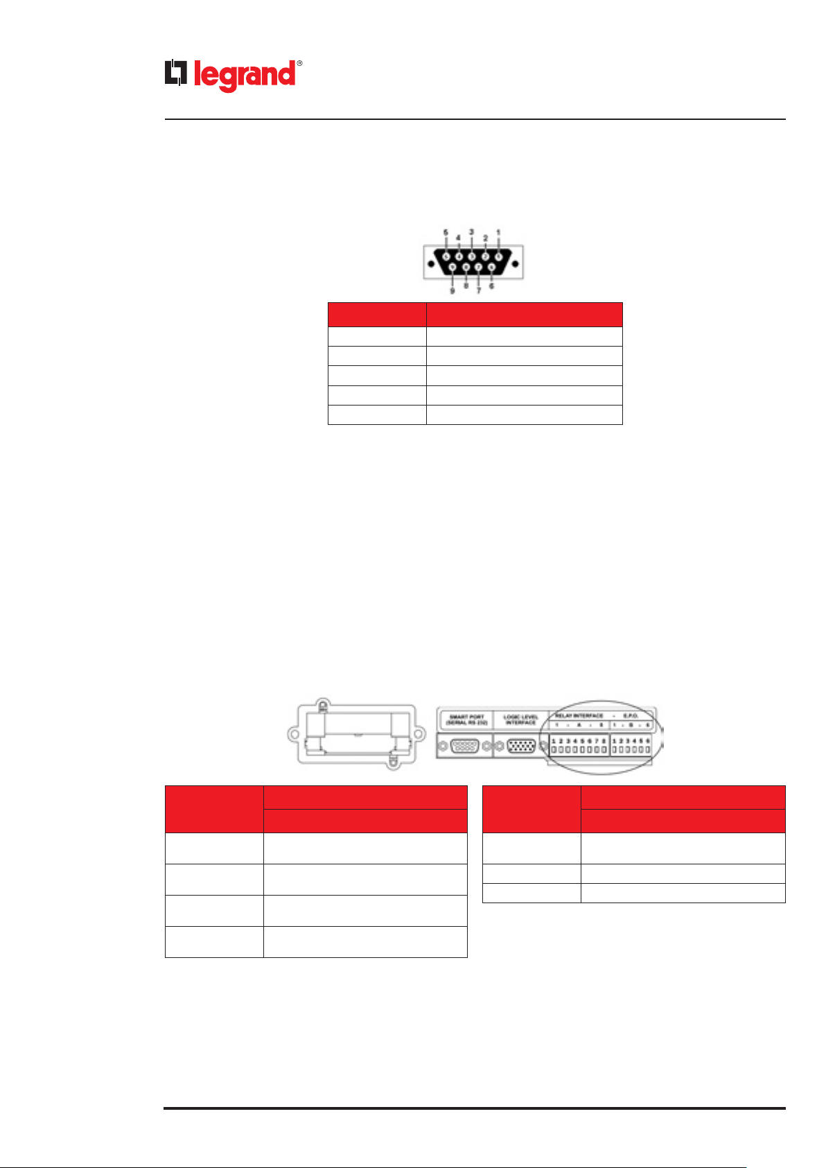
PIN FUNCTION
2 RX
3 TX
5 GND
1 - 4 - 6 connected together
7 - 8 connected together
5.2 Contact interface
The notifications available through this interface are:
• battery mode operation
• autonomy reserve
• generic alarm
• overload
• EPS in bypass mode
• EPS in operating mode
The contacts of the relay interface are programmed in default mode as normally open (NO) and with specific signalling
functions. These settings can be changed by means of the control panel (see section 6.4.2 - path UPS Setup
Dry contacts).
The contacts are available through 8 and 6 pole connectors.
The electric characteristics of the relay interface are the following:
= 250 Vac / 30 Vdc.
- V
MAX
= 5 A.
- I
MAX
PIN
1 - 2
3 - 4
5 - 6
7 - 8
CONNECTOR A
FUNCTION
Contact 1
default: battery mode operation
Contact 2
default: autonomy reserve
Contact 3
Default: generic alarm
Contact 4
default: overload
PIN
1 - 2
3 - 4 EPO (see paragraph 5.3)
5 - 6 -
CONNECTOR B
FUNCTION
Contact 5
default: EPS in bypass mode
24
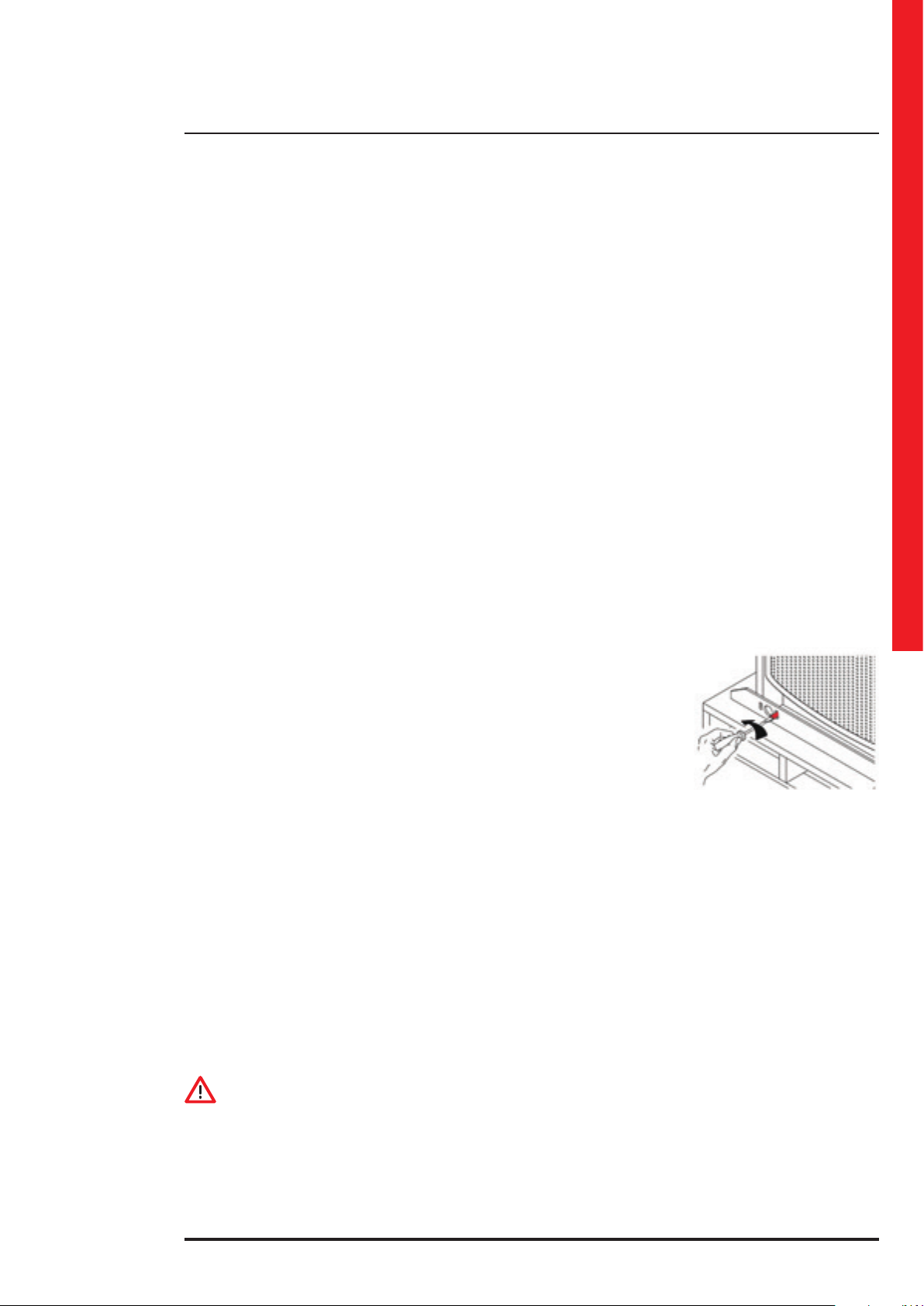
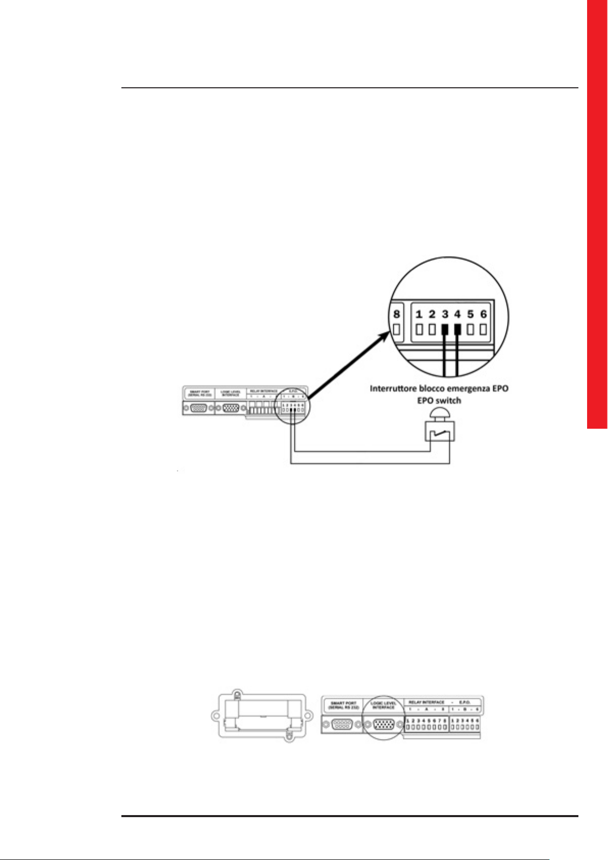
5.3 Emergency Power Off (EPO)
The EPS has an external normally closed contact (NC) that can be opened to activate the immediate stop of the equipment.
The EPO terminal is at the back of the EPS on pins 3 and 4 of the 6-pole connector of the relay interface.
For the correct connection of the EPO, the following requirements must be adhered to:
- use a double-insulation cable of up to 10 meters in length;
- check that the switch used is galvanically isolated.
Page 25
Trimod MCS
INDICATION
It is not possible to connect the EPO circuits of different EPS in parallel. If necessary, use contacts on the EPO emergency
pushbutton isolated from each other.
The electric characteristics of the EPO interface are:
- voltage between terminals 3 and 4 with open circuit: 12Vdc.
- current between terminals 3 and 4 with closed circuit: 5mA.
The figure below shows how the EPO connection must be made:
User manual
5.4 Logic level interface
The logic level interface is available on connector DB15 at the back of the EPS and makes it possible to connect the equipment in remote control mode with the aim of monitoring its operating status.
The following control signals are available:
• Mains/battery operation
• Autonomy reserve
• EPS fault
• Overload
• EPS in bypass mode
• ON/OFF input
The electric characteristics of the logic level interface are:
- Logical output: V
- Power supply: 12 Vdc, I
- Open collector outputs: 30 Vdc, I
= 12 Vdc, impedance on output: 2.2 kΩ in series
MAX
= 700 mA, not regulated.
MAX
= 100 mA.
MAX
25
Page 26

5. Communication devices
PIN FUNCTION
1 GND
2
3
4 Power supply
Mains / Battery
(output, active high)
Autonomy reserve
(output, active high)
6
7
12
13
14
15
5 - 8 - 9 - 10 - 11
Two examples of how the open collector outputs and the TEST IN pin can be used are given below:
(if the output is disabled in normal
mode, it is possible to enable
it in presence of the mains by
connecting the pin to the GND)
(open collector, active low)
(open collector, active low)
(open collector, active low)
(open collector, active low)
(open collector, active low)
Test IN
Overload
EPS in battery mode
EPS in bypass mode
Autonomy reserve
Alarm
do not connect
26
5.5 Network card (SNMP) slot
At the back of the EPS there is a slot for the SNMP card (optional).
The current taken from the SNMP slot for the operation of the network card must be in total less than 700mA.
Page 27

Trimod MCS
6. Control panel
6.1 Description
WARNING
The control panel allows to access some configuration pages of the EPS menu.
Only a skilled technician (paragraph 2.2.1) is authorized to modify the configuration set during the installation. Wrong
settings could lead to injury or material damage to the equipment and the things around it.
The control panel is in the front part of the equipment and consists of an LCD display with 4 x 20 character rows, a backlit
multicolour status indicator and a five keys keyboard.
User manual
LEGEND
1 - 4 line x 20 characters LCD display
2 - ESCAPE key
Main functions:
- exit a function without changing it;
- passage from a lower to a higher menu level;
- exit the main menu and return to the status display;
- silence of the buzzer.
3 - ARROW UP key
Main functions:
- selection of the previous function;
- increase of a value within a function;
-selection of a new item within a function
(e.g. from DISABLED to ENABLED);
- scroll a menu with more than four lines
- change of the page of the main screen.
4 - ARROW DOWN key
Main functions:
- selection of the following function;
- decrease of a value within a function;
-selection of a new item within a function
(e.g. from DISABLED to ENABLED);
- scroll a menu with more than four lines
- change of the page of the main screen.
5 - ENTER key
Main functions:
- confirmation of a value;
- access a menu item;
- passage from a higher to a lower menu level;
- it allows access to the Service Mode.
6 - ON/OFF key
Main functions:
- to turn the EPS on and off;
- to shut down the output phases individually (only with
the EPS set with 3 output independent phases).
7 - multicolour backlit status indicator
27
Page 28

6. Control panel
6.2 Service Mode
This is the operating mode necessary to make the setup during the installation and to manage the software update of the
command board and power modules.
To access this mode, press the ENTER key with the the EPS off until the display shows the text "Service Mode...” At the end
of the start-up procedure, press the ENTER key to access the navigation menu.
It is possible to choose one of the following languages for the text displayed: Italian, English, German, French, Russian,
Spanish, Polish and Portuguese. Follow the path: UPS Setup Operator Panel Language and press the ENTER key
to confirm the choice.
Press the ON/OFF key to exit. Alternatively, the EPS turns off automatically after 20 minutes without receiving manual or
serial commands.
6.3 Main screen
The main screen is shown on the display during EPS operation.
Using the ARROW UP and ARROW DOWN keys it is possible to scroll through the different pages. Every page gives several
information about the status of the equipment.
The pictures of the different pages of the main screen are shown below:
MAIN PAGE DATA DISPLAYED
1 input - output - battery
1st line: Operating status of the EPS. If the text alternates "TRIMOD
MCS” and “EPS in stand-by”, the output is disabled
2nd line: Input voltages
3rd line: Voltage set on output, active power absorbed by the load
and total percentage of the load applied.
4th line: Bar showing the battery residual capacity and the actual
operation time in case of a power failure.
2 input - percentage output - battery
3 bypass - output - battery
4 bypass - percentage output - battery
1st line: Operating status of the EPS. If the text alternates
"TRIMOD MCS” and “EPS in stand-by”, the output is disabled
2nd line: Input voltages
3rd line: Percentage of the load on the output phases
4th line: Bar showing the battery residual capacity and the actual
operation time in case of a power failure.
1st line: Operating status of the EPS. If the text alternates "TRIMOD
MCS” and “EPS in stand-by”, the output is disabled
2nd line: Bypass voltages
3rd line: Voltage set on output, active power absorbed by the load
and total percentage of the load applied.
4th line: Bar showing the battery residual capacity and the actual
operation time in case of a power failure.
1st line: Operating status of the EPS. If the text alternates "TRIMOD
MCS” and “EPS in stand-by”, the output is disabled
2nd line: Bypass voltages
3rd line: Percentage of the load on the output phases
4th line: Bar showing the battery residual capacity and the actual
operation time in case of a power failure.
28
Page 29

MAIN PAGE DATA DISPLAYED
Trimod MCS
User manual
5 load availability on output
6 measurements on output
7 output line voltages
8 measurement on input
1st line: Operating status of the EPS. If the text alternates "TRIMOD MCS”
and “EPS in stand-by”, the output is disabled
2nd line: Phase L1 - power in kVA or in W compared with the rated power or
current compared with the rated one and relative percentage
3rd line: Phase L2 - power in kVA or in W compared with the rated power or
current compared with the rated one and relative percentage
4th line: Phase L3 - power in kVA or in W compared with the rated power or
current compared with the rated one and relative percentage
1st line: Operating status of the EPS. If the text alternates "TRIMOD
MCS
” and “EPS in stand-by”, the output is disabled
2nd line: Output L1 phase: Voltage, current and active power
3rd line: Output L2 phase: Voltage, current and active power
4th line: Output L3 phase: Voltage, current and active power
1st line: Operating status of the EPS. If the text alternates "TRIMOD
MCS
” and “EPS in stand-by”, the output is disabled
2nd line: line voltage between L1 and L2 on output
3rd line: line voltage between L2 and L3 on output
4th line: line voltage between L3 and L1 on output
1st line: Operating status of the EPS. If the text alternates "TRIMOD
MCS
” and “EPS in stand-by”, the output is disabled
2nd line: Input L1 phase: Voltage, current and active power
3rd line: Input L2 phase: Voltage, current and active power
4th line: Input L3 phase: Voltage, current and active power
9 bypass line voltages
10 battery status
Charging -maint
1st line: Operating status of the EPS. If the text alternates "TRIMOD
MCS
” and “EPS in stand-by”, the output is disabled
2nd line: Line voltage between L1 and L2 of bypass line
3rd line: Line voltage between L2 and L3 of bypass line
4th line: Line voltage between L3 and L1 of bypass line
1st line: Operating status of the EPS. If the text alternates "TRIMOD
“EPS in stand-by”, the output is disabled
2nd line: voltage, charging current (negative value when charging in
progress, positive value when the batteries are powering the
equipment)
3rd line: battery capacity percentage compared with the nominal percentage,
time remaining, total autonomy time
4th line: battery status:
- Battery Stand-by
- Discharging
- Reserve autonomy
- End autonomy
- Charging - ph1 - battery recharging status (current limitation)
- Charging - ph2 - battery recharging status (voltage limitation)
- Charging - maint: Battery recharging in maintenance mode
- Charging - oat.: Battery charging in oating mode
- Testing batteries: Battery test in progress
- Equaliz. batteries: Battery equalizing in progress
- BATTERY FAULT: battery voltage less than 100 V
- MaxTime on Battery: End of the maximum set time for battery
mode operation
MCS
” and
29
Page 30

6. Control panel
6.4 Main menu and submenu
Press the ENTER key on the main screen of the display to access the main menu.
The main menu has the following items:
- UPS Status: it allows to check the EPS status in real time;
- UPS Setup: it allows to configure all the EPS functions;
- Power Modules: it allows to analyze the status of the individual power modules in real time;
- Events: it allows to display the events memorized in the EPS history;
- Tools: it allows to carry out a series of functional tests on the EPS;
- Log Out: it allows to end the password-protected session.
Press the ENTER key to access the relative submenus.
The following table sums up all the menu and submenu pages:
UPS Status
(par. 6.4.1)
UPS Info Options PM Status Log View Battery -
UPS Cfg Output Diagnostics (*) Signalling Test (*)
Measures Input
Alarms Bypass Assistance
History Data Batteries
(*) Only available in “Service Mode” (o) Available in password-protected session
The equipment has a menu and relative submenu tree structure, the functions of which are explained in the following
paragraphs.
On the right side of the display, an arrow appears turned downwards or upwards when there are further items to display.
Press the ARROW UP and ARROW DOWN keys to display them.
UPS Setup
(par. 6.4.2)
Operator Panel
Clock Setup
Dry contacts
Power Modules
(par. 6.4.3)
PM SW
update (*)
Events
(par. 6.4.4)
Tools
(par. 6.4.5)
LCD Display Test
(*)
CM errors
recovery
Log Out (o)
(par. 6.4.6)
30
Page 31

6.4.1 UPS Status
UPS Info
Trimod MCS
User manual
Model Equipment model (TRIMOD MCS)
SYNC. address Synchronisation address of the command board
Number of CM Number of command boards recognised
Max VA Maximum apparent power [kVA]
Maw W Maximum active power [kW]
Max Ichg Maximum current available to charge the batteries [A]
SW Ver. Firmware version of the command board
PM SW Ver. Firmware version of the power modules
Boot Ver. Bootloader version in the command board
S/N EPS serial number
UPS Cfg
X/Y -- X/Y - X/Y
Number BCM Number of battery charger module recognised
Installed KB Number of KB installed
Batt.N per KB Number of batteries in series available in one KB
Measures Output X
OUT Single Phase/ Three Phases 120° / Three Phases indep.
IN Single Phase / Three Phases / Inv.3 phases / Undefined (_ _ _)
BYP Single Phase / Three Phases / Inv.3 phases / Undefined (_ _ _)
X Power modules for each phase managed by the command board
Y Power modules for each phase managed by the EPS
Batt. Cap. Capacity of the batteries installed [Ah]
Power Output active power on phase X [W]
Appar. Power Output apparent power on phase X [VA]
Vrms Output effective voltage on phase X [V rms]
Vrms ph-ph
Irms Output effective current on phase X [A rms]
Peak Current Output peak current on phase X [A]
Frequency Pure sine output voltage frequency on phase X [Hz]
I Crest factor Crest factor for phase X
Power fact. Power factor of the load connected to the EPS on phase X
Effective line voltage among the output phases [V rms]
Maw W Maximum active power available on phase X [W]
Power
Max VA Maximum apparent power available by the EPS on phase X [VA]
Appar. Power
INDICATION
To change the value of X and therefore vary the phase from which the data is read, press the ENTER key after entering the
submenu.
Active power on phase X, expressed as a percentage in relation to
the maximum active power available on phase X [%]
Apparent power on phase X, expressed as a percentage
in relation to the maximum apparent power available by the EPS on
phase X [%]
31
Page 32

6. Control panel
Power Absorbed input active power on phase X [W]
Appar. Power Absorbed input apparent power on phase X [VA]
Vrms Effective input voltage of phase X [V rms]
Vrms bypass Effective input voltage of phase X of bypass line [V rms]
Measures Input X
INDICATION
To change the value of X and therefore vary the phase from which the data is read, press the ENTER key after entering the
submenu.
Measures Batteries
Vrms ph-ph Effective line voltage among the input phases [V rms]
Irms Absorbed effective input current on phase X [A rms]
Peak Current Input peak current on phase X [A]
Frequency Pure sine input voltage frequency on phase X [Hz]
I Crest Factor Crest factor for phase X
Power Fact. Power factor of the load connected to the UPS on phase X
Voltage Battery voltage [V]
Current
Residual Cap. Battery charge status, expressed as percentage [0-100%]
(Status)
Total Auton. Total autonomy the EPS would have with batteries 100% charged
Current supplied by the batteries
(negative if the EPS is charging the batteries) [A]
Battery charge operating status:
- Battery Stand-by
- Discharging
- Reserve autonomy
- End autonomy
- Charging - ph1
- Charging - ph2
- Charging - maint.
- Testing batteries
- Equaliz. batteries
- BATTERY FAULT
- MaxTime on Battery
32
Measures Misc.
Resid.Auton. Residual autonomy of the EPS
V Res.Th. Threshold voltage of the string of batteries for autonomy end [V]
Disch.Count Total number of complete battery discharges
Usage
Cal.
Calibr.count Total number of calibrations made
Int.Temp Internal temperature [°C]
Pos.H.V.Bus Voltage on positive DC BUS [V]
Neg.H.V.Bus Voltage on negative DC BUS [V]
Total number of hours in which the EPS has functioned in battery mode [h]
Day and time of the last calibration.
The text “Factory” is displayed if no calibration has yet been made.
Page 33

Alarms Alarm Log. See chapter 7.
INDICATION
To scroll through the list of alarms, press the ARROW UP and ARROW DOWN keys.
UPS RunTime Total runtime
OnBatteryTime Total runtime on battery mode
This batt. Total runtime with the batteries currently installed
CHG Runtime Total battery charger runtime
DrainedOut N. Total number of complete battery discharges
Booster Int. Total number of booster interventions
BypassInterv. Total number of bypass interventions
Batt.calibr. Total number of battery calibrations
Trimod MCS
User manual
History Data
6.4.2 UPS Setup
Options
Chg.cycle N. Total number of battery charge cycles
Batt.equal.N. Total number of battery equalization cycles
Replace batt.N. Total number of times the batteries have been replaced
Load>80% N Total number of times the load has exceeded 80% of the rated load
Load>80% T Total time the load has exceeded 80% of the rated load
Load>100% N Total number of times the load has exceeded 100% of the rated load
Load>100% T
Startup on Battery
Auto Restart If enabled, automatic restarts are permitted
Output options (*)
Total time the load has exceeded 100% of the rated load without
the overload being signalled
If enabled, it allows the EPS to be started up with no mains supply
DISABLED During normal functioning, the output is not powered.
ENABLED During normal functioning, the output is powered.
(*) Only available in the “Service Mode”
33
Page 34
6. Control panel
Voltage This sets the output voltage value [V]
Nominal
value (*)
Frequency
Auto
selection
Output
Inverter (*)
Phases in startup (**)
(*) Available in the “Service Mode” only (**) Available with the inverter set up as three independent phases only
WARNING
Only a skilled technician is authorized to modify the settings on the Output menu
PLL enable
This sets the output configuration and the applied load:
- Single Phase: a unique single phase output
- Three Phases 120°: three phase output suitable for the supply of three
phase loads (e.g. a motor)
- Three Phases indep.: three single phase output lines that are independent of each other
L1 phase
L2 phase
L3 phase
If enabled, the EPS synchronises the output pure sine with that of the
input.
If disabled, the output voltage is not synchronised with the input and it
is indicated with the status light (green) flashing.
This makes it possible to set the output frequency value
(50 Hz or 60 Hz) independently of the input frequency.
If enabled, the EPS detects the frequency of the input
voltage and synchronises the output to the same value.
If disabled, the EPS uses the "Nominal Value” setting.
This makes it possible to program the start-up status for
each output:
- Always ON: phase always on during start-up
- Always OFF: phase always off during start-up
- Last state: phase restored to the status prior to the
shutdown
This makes it possible to select the frequency range in which the EPS
synchronises the output voltage with the input:
- NORMAL: syncronization for frequency variations of ±2% of
Input
PLL Range
Custom PLL Range °
Input Dip Enable This allows the input Dip function to be enabled/disabled
° Available with PLL range set in CUSTOMISED mode
INDICATION
The PLL function ensures that the output frequency is synchronised with that of the input, guaranteeing that passage
through zero (zero-crossing) occurs at the same moment. The input-output synchronisation is guaranteed even in case of
bypass intervention (e.g. because of overload).
INDICATION
By disabling the PLL function, the automatic bypass function is deactivated as well.
The equipment turns off in case of an extended overload.
WARNING
Only a skilled technician is authorized to modify the settings on the Input menu
the nominal value
- EXTENDED: syncronization for frequency variations of ±14% of the
nominal value
- CUSTOM: this can be set by the user (see the next menu item)
This makes it possible to set the customised frequency interval in which
the EPS synchronises the output voltage with the input.
The value can be selected from a minimum of 0.5 Hz to a maximum of
7.0 Hz with 0.1 Hz step
34
Page 35

Bypass
If enabled, the EPS manages the bypass intervention automatically.
Bypass enable
Forced Mode If enabled, the EPS activates the bypass permanently
DIP speed
O-Line Mode
Startup on Bypass
If disabled, the EPS never switches to bypass mode so in the case of an
extended overload or in the case of failure and absence of redundancy,
it turns off.
It allows to vary the switching circuit sensitivity:
- SLOW: indicated for loads that are not sensitive to voltage fluctuations
and that cause current peaks
- STANDARD: normal mode
- FAST: for all loads that are highly sensitive to voltage fluctuations
If enabled, the EPS operates in eco mode.
During the operation, the load is powered directly by the automatic
bypass circuit. If there is a power failure or the voltage input tolerance
is exceeded, the EPS activates the inverter thereby powering the load
through the batteries.
If enabled, on mains start-up the initial powering of the load occurs via
bypass.
If disabled, the inrush current is managed by the inverter as in a battery
start-up.
Trimod MCS
User manual
WARNING
Only a skilled technician is authorized to modify the settings on the Bypass menu
This sets the start time of the battery autonomy warning [min]
This sets the maximum operating time in
battery mode. Once this time has elapsed,
the EPS turns off. Set at OFF to disable the
function
If enabled, it activates the battery charge
with the EPS off
This enables or disables the restart of the
EPS when the mains returns after the total
discharge of the batteries
This sets the percentage charge value
of the batteries to be reached with the
standby charge function in order to restart
automatically the EPS after a total battery
discharge.
Batteries
Reserve Time
Threshold Values
MaxTime on Battery
Charger Standby Charge
Restart Enable
Auto Restart
Min. Autonomy
This sets the total number of KB installed. The parameter is necessary
Total KB
for the EPS to provide correct values for the autonomy based on the
load applied and for a correct battery charge.
Capacity (*) This sets the capacity value of the batteries in the EPS [Ah].
(*) Available in the “Service Mode” only
WARNING
Only a skilled technician is authorized to modify the settings on the Batteries menu
35
Page 36

6. Control panel
Language This sets the language on the display
Buzzer This enables/disables all the sound signals
Keyboard Beep This enables/disables the key pressure sound
Locked turn off (*) If enabled, the password is required to shutdown the equipment
Operator
Panel
(*) Only available with the chosen password.
Clock Setup DD/MM/YY – HH:mm:SS
Display Backlight
Display Contrast This sets the display contrast
Password Change This sets a password that blocks access to the settings
Password level It indicates the level of the password (the default value is USER)
This sets the backlighting of the display:
- FIXED: always lit
- TIMED: the backlighting turns off after one minute
of keyboard inactivity
- DISABLED: always off
This sets the date/time of the EPS. By pressing the ENTER key, the
value to modify is selected. By pressing the ARROW UP/DOWN keys,
the selected value is increased or decreased.
DD: day
MM: month
YY: year
HH: hour
mm: minutes
SS: seconds
Dry contacts
Contact 1
Contact 2
Contact 3
Contact 4
Contact 5
All
This allows the signal to be associated with the
contact:
- Mains/Battery
Function
Setup
Function
Setup
Function
Setup
Function
Setup
Function
Setup
This allows to set for all the contacts:
- NORMALLY CLOSED
- NORMALLY OPEN
- Runtime autonomy
- Alarm
- Overload
- Bypass
- UPS is working
This allows to set the type of contact:
- NORMALLY CLOSED
- NORMALLY OPEN
(see contact 1)
(see contact 1)
(see contact 1)
(see contact 1)
36
Page 37

6.4.3 Power Modules
Trimod MCS
User manual
Mod. Model of power module X
SW Ver. Version of the firmware inside power module X
HW Ver. Hardware version of power module X
PM Status
PM Info X
S/N Serial number of power module X
Max VA Maximum apparent power supplied by power module X [VA]
Maw W Maximum available active power supplied by power module X [W]
Max Ichg
Input X
Maximum current available from the battery charger of power module X [A]
Power
Appar.Power
Vrms Effective input voltage to the power module X [V rms]
Vrms bypass
Vrms ph-ph Input line voltage to the power module X [V rms]
Irms
Peak Current Peak current of the power module X [A]
Frequency
I Crest factor Crest factor applied by power module X to the mains
Power fact. Power factor applied by power module X to the mains
Power Active power supplied by power module X [W]
Active power absorbed by the mains by power module X [W]
Apparent power absorbed by the mains by power module X [VA]
Effective input voltage to the power module X of the bypass
line [V rms]
Effective current absorbed by the mains supplied by power
module X [A rms]
Pure sine input frequency voltage of power module X
for the bypass line [Hz]
PM
Measures
Output X
Appar.Power Output apparent power supplied by power module X [VA]
Vrms Effective output voltage of power module X [V rms]
Vrms ph-ph Effective output line voltage of power module X [V rms]
Irms
Peak Current Output peak current of power module X [A]
Frequency Pure sine output voltage frequency of power module X [Hz]
I Crest factor Crest factor of the output current of power module X
Power fact. Output power factor for power module X
Maw W Maximum available active power from power module X [W]
Power
Max VA
Appar.Power
Effective output current supplied by power module X [A rms]
Output active power supplied by power module X,
expressed as a percentage in relation to the maximum active
power available from power module X [%]
Maximum apparent power available from power module X [VA]
Apparent power supplied by power module X, expressed as
a percentage in relation to the maximum apparent power
available from power module X [%]
(continue)
37
Page 38
6. Control panel
PM
Measures
PM Status
PM
History
Data
Voltage Battery voltage detected by power module X [V]
Battery X
Misc. X
Run Time Total runtime
Batt.Time Total runtime on battery mode
Chg.Time Total battery charger runtime
Bypass int. Total number of bypass interventions
Battery int. Total number of transfers to battery mode
Dumper int. Total number of dumper interventions
Mains High
Overheat N. Total number of overheating
Overload N. Total number of overloads
HVBus Run.N. Total number of overvoltages on the BUS
OutDCLevel N.
Current
Charger Status of the battery charger inside the power module X
INV HSink
Temp.
BST HSink
Temp.
Fan Speed Fan speed of power module X expressed as a percentage [%]
Pos.H.V.Bus Voltage on the positive DC BUS of power module X [V]
Neg.H.V.Bus Voltage on the negative DC BUS of power module X [V]
Total number of times that the input line voltage has exceeded the maximum permitted value by the power module
Total number of presence of DC output voltages to the power module
Current required to the batteries by power module X
(negative if the batteries are charging) [A]
Temperature of power module X Inverter heat sink [°C]
Temperature of power module X Booster/PFC heat sink [°C]
INDICATION
Press the ENTER key to change the X value that represents the power module number the data are read from. The X value
starts from 0 that represents the first power module installed in the first tunnel at the top left.
Diagnostics (*) PM errors recovery
Update all PM
PM SW
update (*)
Single PM SW update
(*) Available in the “Service Mode” only
CAUTION
Only a skilled technician is authorized to carry out an update.
This deletes the error memory detected in the power module.
It deletes only the resettable errors.
This allows the sequential and automatic update of the internal
software in all the power modules.
Press the ENTER key to start the procedure.
If the update is not necessary, the message “PM SW Versions updated!” appears on the display.
Press the ESC key to exit.
This allows the internal software update of a single power module.
Use the ARROW UP/DOWN keys to choose the module that has to be
updated (‘PM00’ indicates the first power module installed in the first
tunnel at the top left).
Press the ENTER key to display a comparison between the software
currently present in the selected module and the new software to be
installed. Press the ENTER key to start the update procedure. When
the update is complete, the message “PM SW Version updated!”
appears on the display. Press the ESC key to exit.
38
Page 39

6.4.4 Events
Events
6.4.5 Tools
Battery
Critical
Log View
Battery Test Automatic
Batt. Calibration
Battery cycle
Warning
Info
This calibrates the batteries, finding the discharge curve.
For precise information about the battery charge status, it is necessary to
perform the calibration in the following cases:
- after installation and first start-up;
- in case the batteries are replaced;
- every six months after the first year of the EPS life.
This carries out a battery test and their equalization to check the status,
the performance and to maximise the battery life.
Trimod MCS
User manual
All This displays all the events
This displays the events that have generated
critical alarms
This displays the events that have generated
non-critical alarms
This displays the events that have generated
simple warnings
This performs a test on the batteries to check their
status and performance
Signalling Test (*)
LCD Display Test
(*)
(*) Available in the “Service Mode” only
Assistance
CM errors recovery
This carries out the test of the status indicator signalling (green, orange and red) and of the
acoustic notfication.
This performs the test of the alphanumeric display. Press the ENTER key to display all the available characters.
Display
Identifier
Use code Enter the code provided by the Technical Support Service.
This deletes the error memory detected by the command board.
It restores only the resettable errors.
This displays the code to communicate to the Technical Support Service.
6.4.6 Log Out
It is possible to set a password to prevent non-authorised personnel to modify the configuration.
By choosing a password, it is necessary to enter a private session to modify the settings. At the end of the operations use
the "Log Out" menu to leave the private session.
If the password has been forgotten, it is necessary to contact the LEGRAND Technical Support Service.
39
Page 40
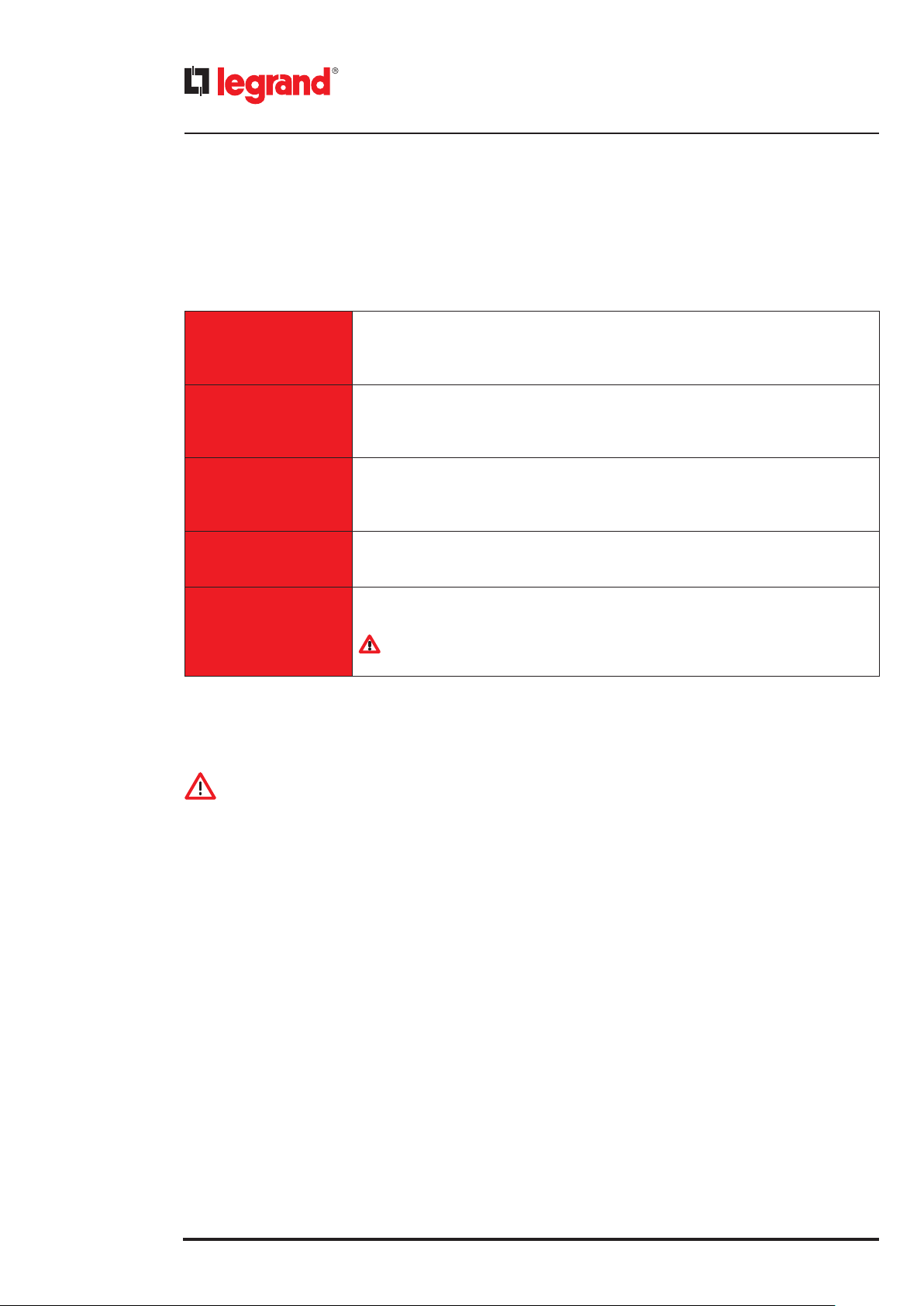
6. Control panel
6.5 POWER ON/OFF menu
When the EPS is on, it is possible to access a menu called POWER ON/OFF by pressing the ON/OFF pushbutton for less
than 0,5 seconds.
The choices that can be made in this menu are the following:
Press the ENTER key to access the submenu in which it is possible to choose whether to
L1 phase (**)
L2 phase (**)
L3 phase (**)
UPS
Hot swap
(**) Available with the inverter set up as three independent phases only
turn phase L1 on or o independently of the others.
Press the ARROW UP/DOWN keys to choose the ON or the OFF value. Press the ENTER key
to conrm the value. Press the ESC key to leave the submenu.
Press the ENTER key to access the submenu in which it is possible to choose whether to
turn phase L2 on or o independently of the others.
Press the ARROW UP/DOWN keys to choose the ON or the OFF value. Press the ENTER key
to conrm the value. Press the ESC key to leave the submenu.
Press the ENTER key to access the submenu in which it is possible to choose whether to
turn phase L3 on or o independently of the others.
Press the ARROW UP/DOWN keys to choose the ON or the OFF value. Press the ENTER key
to conrm the value. Press the ESC key to leave the submenu.
Press the ENTER key to access the submenu to switch the EPS o.
Press the ENTER key again to switch the equipment o. Press the ESC key to leave the
submenu.
Press the ENTER key to access a submenu to make the hot-swap substitution of the power
modules.
CAUTION
This operation CANNOT BE PERFORMED
6.6 Switching off the EPS
CAUTION
The shutdown procedure must be applied exclusively if the load is off or does not need to be supplied by the EPS.
There are two possible ways to shut down the UPS.
It is possible to shut down the UPS from the POWER ON/OFF menu or it is possible to perform the following procedure:
1. Keep the ON/OFF key pressed for at least two seconds.
2. The display shows the text "Turn off the UPS?". Press the ENTER key.
3. Wait for the shutdown operations to complete.
If a prolonged shutdown is planned, apply what is prescribed in chapter 9.
6.7 Switching on the EPS
The operator can turn the equipment on with the following procedure:
1. Press the ON/OFF key.
2. When the display shows the text “<ENTER> to confirm UPS turn ON”, press the ENTER key. If no operation is carried out
within 30 seconds, the EPS turns off.
If the display shows the message "WARNING: different UPS setup! <ENTER> to confirm UPS turn on”, the EPS setup is
different from the last power up. A skilled technican must check the setup before confirming the power up.
3. Wait for the power up operations to complete. The load is only supplied when the bar with the text “UPS initialize...”
displayed reaches the end and the main screen appears.
40
Page 41

Trimod MCS
7. Diagnosis
7.1 Luminous and audible notifications
The status indicator of the control panel and the led on the front of every power module change their colour according
to the actual operating status of the EPS. This status is shown in the table below.
INDICATION
Some luminous notifications come with an audible notification. Press the ESC key to silence the buzzer. On every subsequent press, the buzzer is silenced or enabled.
INDICATION
If it is not possible to solve the problem, contact the LEGRAND Technical Support Service.
User manual
STATUS
INDICATOR
GREEN
Steady
GREEN
Steady
ORANGE
Steady
- - - 3V Battery Fail
GREEN
Steady
ORANGE
Flashing
GREEN
Steady
ORANGE
Flashing
GREEN
Steady
GREEN
Quick flashing
POWER MODULE
LED
GREEN
Steady
ORANGE
Flashing
ORANGE
Flashing
- -
1 module:
Steady ORANGE
Remaining modules:
Steady GREEN
GREEN
Quick flashing
AUDIBLE
NOTIFICATION
-
-
-
-
- -
STATUS
MESSAGE
Trimod
MCS
TRIMOD MCS
EPS in
stand-by
Output/phase
turned OFF
Modules
turned OFF
Equalizing
Battery
UPS STATUS DESCRIPTION AND
OPERATING TIPS
Normal EPS operation
with mains present, load within
the limits and output enabled
Normal EPS operation
with mains present, load within
the limits and output disabled
Contact the LEGRAND Technical Support
Service
Phase OFF in configuration of
3 independent phases output.
Check the output setup.
Command board in Hot Swap
Battery equalization in progress
Mains supply is absent on at least one
power module and/or the frequency of
the mains is not correct (>68Hz or <43Hz)
and/or the input PLL is not synchronised.
A skilled technician must check the input
mains.
GREEN
Quick flashing
GREEN
Quick flashing
ORANGE
Quick flashing
ORANGE
Steady
ORANGE
Steady
- - -
GREEN
Quick flashing
ORANGE
Flashing
ORANGE
Steady
ORANGE
Steady
- Bypass line KO
-
ON 500 ms
and OFF 12 s
- Battery Cal.. Battery calibration in progress
One or more of the following problems
are present: bypass absent, input PLL not
synchronised, bypass voltage outside
the limits, bypass three-phase circuit
sequence not correct or reversed, bypass
frequency out of tolerance.
A skilled technician must check the
The bypass line cannot be used to power
Forced on Bypass
UPS on Bypass
UPS on Battery Battery mode operation
Operation in forced bypass mode
bypass line.
the load
continue...
41
Page 42

7. Diagnosis
STATUS
INDICATOR
ORANGE
Steady
ORANGE
long intermittent
ORANGE
long intermittent
ORANGE
Quick flashing
ORANGE
Short and double
intermittent with
pause
RED
Steady
RED
Steady
RED
Quick flashing
RED
Quick flashing
RED
Quick flashing
RED
Quick flashing
POWER MODULE
LED
- - Battery Test... Battery test in progress
GREEN
Steady
GREEN
Steady
ORANGE
Flashing
ORANGE
Steady
RED
Steady only on the
module with the
fault
RED
Steady only on the
module with the fault
ORANGE
Flashing
RED
Quick flashing
RED
Short and double
intermittent with pause
RED
Short and double
intermittent with pause
AUDIBLE
NOTIFICATION
-
-
-
Short
intermittent
blinks and
double with
pause
Quick flashing
Quick flashing
Quick flashing BATTERIES KO
Quick flashing
Quick flashing
Quick flashing
STATUS
MESSAGE
Make
Maintenance
Check
Batteries
Maintenance
Bypass
RUNTIME
RESERVE!
FAULT
CHARGER
FAU LT
MODULE
BATTERY
DISCONNECTED
BATTERY
RUNAWAY
HVBUS
RUNAWAY FAIL
UPS STATUS DESCRIPTION AND
OPERATING TIPS
Contact the LEGRAND Technical Support
Service
A skilled technician must check the
battery status
Operation in manual bypass mode
Autonomy reserve during the battery
mode operation
Battery charger faulty on at least one
power module.
A skilled technician must replace the
faulty module.
A skilled technician must replace the
faulty power module.
Batteries failed.
A skilled technician must check the
batteries.
Batteries failed or not connected.
A skilled technician must check the
batteries.
Excessive battery voltage.
If the alarm persists over time a skilled
technician must check the batteries.
Contact the LEGRAND Technical Support
Service
42
RED
Quick flashing
RED
Quick flashing
RED
Quick flashing
RED
Quick flashing
RED
Quick flashing
RED
Quick flashing
RED
Steady
RED
Short and double
intermittent with
pause only on the
module in alarm
RED
Short and double
intermittent with
pause only on the
module in overload
- Quick flashing CM FAILURE
- Quick flashing
- Quick flashing BACKFEED
Quick flashing
Quick flashing OVERHEAT
Quick flashing OVERLOAD
OUT DC
LEVEL FAIL
Reference
Error!
or
Reference
Warning
Reset the power module error from the
control panel in Service Mode (paragraph
6.4.3) and turn on the EPS. If the error persists,
one or more power modules are faulty and a
skilled technician must replace them.
Overheating of one or more power
modules. Check the operation of the
module fans and clean the air intake
grilles.
Overload on one or more power
modules.
Check the applied load.
Contact the LEGRAND Technical Support
Service
Contact the LEGRAND Technical Support
Service
Contact the LEGRAND Technical Support
Service
Page 43

Trimod MCS
7.2 Messages
This paragraph shows the messages that appear on the control panel display or in the event list (see paragraph 6.4.4) and
the probable cause that could have generated them.
INDICATION
If it is not possible to solve the problem, contact the LEGRAND Technical Support Service.
FIRST ROW OF THE MAIN SCREEN
MESSAGE MEANING AND OPERATING TIPS
TRIMOD MCS The EPS is operating properly
User manual
Service mode
UPS initialize... The EPS is starting-up
CM initialize...
CM turning off...
Service Mode... The EPS is starting up in Service Mode.
Maintenance Bypass The load is powered directly from the mains by means of the manual bypass.
Forced on Bypass
UPS on Bypass EPS in bypass mode.
Bypass line KO A skilled technician must check the bypass line.
EPS in stand-by Output non powered during normal functioning (with mains present)
Modules turned OFF
Output/phase turned OFF
UPS on battery
EPS in Service Mode. The parameters can be modied through the control
panel and updates can be made.
The command board is starting-up all the associated power modules after the
exit from the hot-swap mode.
The command board is turning off all the associated power modules after
entering the hot-swap mode
The EPS has entered the forced Bypass mode through a selection from the
control panel.
Command board in hot-swap.
The power modules are no longer powered and ready to be replaced.
Phase or Output o. Conguration obtained via display or after a EPS
malfunctioning.
EPS in battery mode. A fault in the equipment power supply system or a loss of
mains has occurred.
UPS in off-line
Battery Cal...
Battery Test...
Equalizing Battery The EPS is performing battery equalization.
Buzzer Muted The buzzer has been silenced.
RUNTIME RESERVE! The battery charge is low while the EPS is working in battery mode.
FAULT MODULE One or more power modules are faulty. A skilled technician must replace them.
The load is powered directly from the bypass line. In case of a power failure,
the equipment switches to battery mode.
The EPS is performing the calibration of the batteries through a command
from the control panel.
The EPS is carrying out a test on the batteries in order to check their status and
proper operation.
continue...
43
Page 44

7. Diagnosis
MESSAGE MEANING AND OPERATING TIPS
BACKFEED
FAULT CHARGER
BATTERIES KO
BATTERY DISCONNECTED
STRONG OVERLOAD The load has caused an excessive lowering of the output voltage.
OVERLOAD The load is higher than the rated power of the EPS.
OVERHEAT
OUT DC LEVEL FAIL
HVBUS RUNAWAY FAIL Contact the LEGRAND Technical Support Service.
BATTERY RUNAWAY
3V Battery Fail
A backfeed error has been detected.
Contact the LEGRAND Technical Support Service.
The battery charger circuit of one or more power modules is faulty.
A skilled technician must replace them.
Batteries failed. A skilled technician must check their status and replace them
if necessary.
The EPS detects a battery voltage lower than 10 V.
A skilled technician must verify the batteries and the cabling.
The temperature inside the EPS is outside the nominal range. Check the
operation of the module fans and clean the air intake grilles.
Reset the power module error from the control panel in Service Mode (paragraph 7.4.3) and turn on the EPS. If the error persists, one or more power
modules are faulty and a skilled technician must replace them.
The battery voltage is out of control. A skilled technician must check the status
of the batteries and of the battery charger.
The 3V battery of the command board is exhausted. Contact the LEGRAND
Technical Support Service.
Abnormal batt.drain Abnormal battery drain. Contact the LEGRAND Technical Support Service.
Check Batteries A skilled technician must check the battery status.
Make Maintenance Contact the LEGRAND Technical Support Service.
Shutdown ongoing... The EPS is shutting down after being programmed to do so by the user
Charging Battery
UPS EMERGENCY! Contact the LEGRAND Technical Support Service.
LOAD TURNED OFF!
UPS TURNED OFF! The EPS is turning o due to a command given from the control panel.
UPS BLOCKED! Contact the LEGRAND Technical Support Service.
PM FW not updated!
Reference Error!
CM FAILURE
Reference Warning
The EPS is charging the batteries. The charging mode is indicated next to the
message.
A prolonged excessive load (e.g. a short circuit) has caused a signicant
lowering of the output voltage and the load is no longer powered or the load
has been shut down because of an extended overload in battery mode.
One or more power modules have the software not compatible with the command board.
Update the modules before turning on the EPS.
Synchronisation error among the command boards.
Contact the LEGRAND Technical Support Service.
Communication error among the command boards.
Contact the LEGRAND Technical Support Service.
Synchronisation error among the command boards.
Contact the LEGRAND Technical Support Service.
44
Page 45

ALARMS
Trimod MCS
User manual
MESSAGE MEANING
INVERTER FAIL
BOOSTER FAIL
CHARGER FAIL
OVERHEAT Overheating. Check the ventilation system.
OVERLOAD Overload. Check the connected load level.
HVBUS RUNAWAY Contact the LEGRAND Technical Support Service
OUTPUT DC LEVEL ERROR
BATTERY VOLTAGE TOO HIGH Excessive battery voltage. A skilled technician must check the batteries.
MODULE COMMUNICATION FAIL
PM -> CM
BATTERY WIRING FAIL
MAINS WIRING FAIL
H.V.BUS WIRING FAIL
BATTERY DISCONNECTED OR
POLARITY INVERTED
MODULE COMMUNICATION FAIL
CM -> PM
Fault detected in the Inverter circuit. One or more power modules are faulty. A
skilled technician must replace them.
Fault occurred in the Booster/PFC circuit. One or more power modules are
faulty. A skilled technician must replace them.
Fault occurred in the Battery charger circuit. One or more power modules are
faulty. A skilled technician must replace them.
A skilled technician must check that there is not a faulty power module or a
voltage backfeed from the output.
Failure in the communication with the power modules.
Contact the LEGRAND Technical Support Service.
Error in the battery connection with the power modules.
One or more modules are faulty. A skilled technician must replace them.
Error in the mains connection with the power modules.
One or more modules are faulty. A skilled technician must replace them.
Error in the DC bus connection with the power modules.
One or more modules are faulty. A skilled technician must replace them.
The batteries were not connected correctly or the polarity has been inverted
Failure in the communication with the power modules.
Contact the LEGRAND Technical Support Service.
UNPROTECTED LOAD Load not protected
MAKE MAINTENANCE Contact the LEGRAND Technical Support Service
CHECK BATTERIES A skilled technician must check the battery status
REFERENCE ERROR OVER CAN
NETWORK!
CM FAILURE ON CAN NET
BACKFEED
ABNORMAL BATTERY DRAIN Abnormal battery drain. Contact the LEGRAND Technical Support Service.
Synchronisation failure among the command boards.
Contact the LEGRAND Technical Support Service.
Synchronisation failure among the command boards.
Contact the LEGRAND Technical Support Service.
A backfeed error has been detected.
Contact the LEGRAND Technical Support Service.
45
Page 46

7. Diagnosis
SCREEN DISPLAYED ON START-UP OR SHUT DOWN
MESSAGE MEANING AND OPERATING TIPS
First Turn ON: Supply Mains!
Mains not Present!
Startup not Allowed
Emergency Power Off!
Incomplete Setup
for start-up!
Three Phase Voltage Sequence
Invalid!
Invalid PM SW Versions:
to execute update
Invalid PM HW Versions!
START UP Error!
Startup aborted
UPS turned off by program! EPS shut down as programmed via software in a remote control system
The EPS has never been turned on. No mains input. Start-up not permitted.
Make sure the mains is present before turning on.
No mains input. Start-up not permitted.
To start the EPS in battery mode select this conguration from the control
panel (paragraph 6.4.2).
The Emergency Power O (EPO) has been activated. The EPO command has
been sent by a pushbutton or a disconnector switch on the input line has been
opened during the operation of the EPS. Check the emergency pushbutton.
The EPS requires a complete conguration for start-up.
Check that the output conguration, bypass enabling, number of KB, number
of batteries per KB and output voltage have been inserted properly.
The three phase input sequence is not valid. A skilled technician must check
that the input three phase system has been correctly connected.
The SW versions of some or of all the power modules are not correct.
Press the ENTER key to update.
At the end of the update, the EPS continues the start-up procedure.
One or more power modules are not compatible with the EPS.
Contact the LEGRAND Technical Support Service.
An error has occurred during the start-up procedure of the EPS.
Contact the LEGRAND Technical Support Service.
The EPS start-up has not been conrmed from the control panel within 30
seconds after the conrmation request of the start-up procedure.
Incorrect setup turn-off
Incorrect KB setup turn-off
Low Battery TurnOff
Battery Start up Failed.
Check polarity.
Battery Time Expired
Load turned OFF The load power has been cut o
Powered from Output
Turned Off with charged H.V.bus
Saving NVData error
Invalid CM SW Versions:
Execute update!
An error has occurred during the conguration. EPS is shutting down.
One or more parameters have not been set properly.
Check the conguration from the control panel.
An error has occurred during the conguration of the number of KB.
Set the right number of KB from the control panel (paragraph 6.4.2)
EPS shutdown during battery mode because the minimum voltage level of the
batteries has been reached.
The batteries are not connected to the EPS or the BUS is not properly charged.
A skilled technician must check the batteries.
EPS shutdown during battery mode because the maximum battery operating
time set from the control panel has been reached (paragraph 6.4.2)
Start-up error. Voltage present on the equipment output.
A skilled technician must check the connections.
The EPS has not shutdown properly. Make sure the DC buses are discharged
before performing any maintenance operation.
Error saving some EPS parameters. If the problem persists, contact the
LEGRAND Technical Support Service.
The command boards have been programmed with dierent software
versions. The software versions must be aligned by carrying out an update of
the command boards through a PC.
46
Page 47

MESSAGES DISPLAYED ON START-UP
MESSAGE MEANING AND OPERATING TIPS
Trimod MCS
User manual
WARNING:
alarm records in memory!
WARNING: different UPS setup!
Maintenance Bypass!
Open output
Turn ON after low battery turn OFF.
<ENTER> to confirm UPS turn ON Press the ENTER key to turn on the EPS
CRITICAL EVENTS (paragraph 6.4.4)
MESSAGE MEANING AND OPERATING TIPS
Inverter Fail
Booster Fail
Battery Charger Fail
Overheat Overheating. Check the ventilation system.
Overload Overload. Check the connected load level.
It is necessary to conrm the turning on of the EPS in presence of alarms in the
even list
The EPS conguration has changed from the last power up. A skilled technican
must check the setup before conrming the power up.
Open the output breaker before turning on the EPS to exit the manual maintenance bypass mode.
The EPS is turned on after a previous end of autonomy
Fault detected in the Inverter circuit. One or more power modules are faulty. A
skilled technician must replace them.
Fault detected in the Booster/PFC circuit. One or more power modules are
faulty. A skilled technician must replace them.
Fault detected in the Battery charger circuit. One or more power modules are
faulty. A skilled technician must replace them.
H.V.Bus Runaway Failure Contact the LEGRAND Technical Support Service
Output DC Level
Battery voltage too high Excessive battery voltage. A skilled technician must check the batteries.
Power Module comm. failure Contact the LEGRAND Technical Support Service
Emergency Contact the LEGRAND Technical Support Service
Load turned OFF The output load power has been cut o
Irregular TurnOff
Overload TurnOff EPS shutdown due to an extended overload
Emergency Power Off turn-OFF EPS shutdown due to an Emergency Power O
Battery KO Fault in the batteries. A skilled technician must check them.
Power Module battery wiring
failure
Power Module mains wiring failure
A skilled technician must check that there is not a faulty power module or a
voltage backfeed from the output
EPS shutdown in an anomalous way. The skilled technician must make sure
that there is no voltage inside the equipment before performing any maintenance operation.
There is a fault in the connection of the batteries to the power modules. One or
more power modules are faulty. A skilled technician must replace them.
There is a fault in the connection of the mains to the power modules. One or
more power modules are faulty. A skilled technician must replace them.
continue...
47
Page 48

7. Diagnosis
MESSAGE MEANING AND OPERATING TIPS
Power Module HVBus wiring
failure
Communication failure
between CM
Backfeed
Abnormal battery drain Abnormal battery drain. Contact the LEGRAND Technical Support Service.
NOTIFICATION EVENTS (paragraph 6.4.4)
MESSAGE MEANING AND OPERATING TIPS
Low Battery TurnOff EPS shutdown due to autonomy end during the battery mode operation.
Invalid sequence turn-OFF
Battery calibration aborted Battery calibration interrupted by the user
Battery Time Expired
StartUP error Start-up error.
Start-up granted with alarms EPS start-up authorised in presence of alarms
There is a fault in the connection of the HVBus to the power modules. One or
more power modules are faulty. A skilled technician must replace them.
Communication error among the command boards.
Contact the LEGRAND Technical Support Service.
A backfeed error has been detected. Contact the LEGRAND Technical Support
Service.
EPS shutdown due to incorrect three phase sequence on input. A skilled
technician must check that the input three phase system has been correctly
connected.
Shutdown of the EPS because the maximum battery operating time set from
the control panel has been reached (paragraph 6.4.2)
Start-up granted with new cfg
Incorrect setup turn-off
PM firmware updated Power module software updated
Strong overload Strong overload
Powered from Output
Turned Off with charged H.V.bus
Make Maintenance Contact the LEGRAND Technical Support Service.
Check Batteries A skilled technician must check the batteries.
Replace batteries
Low Battery Emergency The load is powered directly from the bypass line due to an end of autonomy
Charge finished
Battery disconnected
or polarity inverted
EPS start-up authorised with new conguration.
The number of power modules installed on the UPS has changed.
EPS shutdown because the conguration is wrong.
The number of power modules detected by the EPS is not correct for the output conguration set.
Voltage present on the EPS output. A skilled technician must check the connections.
The EPS has not shutdown properly.
The EPS has shutdown without completely discharging the buses.
A skilled technician must check the battery status and change the batteries if
necessary.
Faulty operation of the battery charger. Contact the LEGRAND Technical
Support Service.
The batteries were not connected correctly or the polarity has been inverted
48
Page 49

INFORMATIVE EVENTS (paragraph 6.4.4)
MESSAGE MEANING
User Turn ON User start-up of the EPS
User Turn OFF User shutdown of the EPS
Auto turn ON Automatic EPS start-up
Trimod MCS
User manual
Timed turn OFF
Stand-by battery charge start The battery charger has started in EPS stand-by mode
UPS on battery The EPS has transferred to battery operation mode
UPS on mains The EPS has transferred to mains operation mode
Line Out turned OFF The EPS output has been shut down
Battery test executed Battery testing successfully completed
Battery learning executed Battery calibration successfully completed
Forced Bypass ON The forced bypass operation mode has been enabled
Forced Bypass OFF The forced bypass operation mode has been disabled
Maintenance Bypass ON The load is powered directly from the manual bypass disconnector switch
Maintenance Bypass OFF
Enter in Hot Swap The equipment has started-up the hot-swap mode
Exit from Hot Swap The equipment has exited the hot-swap mode
The EPS has been shut down via the delayed shutdown programming
(paragraph 6.4.2)
The load is no longer powered directly from the manual bypass disconnector
switch
Event list erased The event list has been erased
Battery replaced The batteries have been replaced by the LEGRAND Technical Support Service
49
Page 50

8. Installation and maintenance
DANGER
INSTALLATION and ORDINARY MAINTENANCE operations must be carried out only by SKILLED TECHNICIANS
(paragraph 2.2.1). The EXTRAORDINARY MAINTENANCE operations must be carried out only by the LEGRAND
TECHNICAL SUPPORT SERVICE.
8.1 Introduction
This chapter contains all the information necessary for an operator to correctly install and maintain the EPS.
DANGER
The operator is not authorised to perform the operations contained in the installation and maintenance manual.
LEGRAND declines all liability for any injury or damage caused by activities carried out differently from the instructions
in this manual or by a skilled technician who does not observe the requirements laid down in the installation and maintenance manual.
8.2. Installation
The operator is not authorized to install and electrically connect the EPS. These operations are the sole preserve of a skilled
technician (paragraph 2.2.1) who must follow the instructions addressed to him in the installation and maintenance
manual.
8.3 Preventive maintenance
The EPS does not contain parts for preventative maintenance by the operator.
The operator must periodically perform:
- a normal general external cleaning;
- a check to verify the absence of alarms on the display;
- a check to verify the correct operation of the fans on each power module.
After the first year of EPS life, check the batteries every six months through the "battery calibration" function to guarantee
the optimal operation and continuous protection of the connected load. With this function, the EPS detects the discharge
curve of the batteries in order to provide precise information on the charging status.
To activate the function enter the main menu and follow the path Tools Batteries Batt. Calibration
Press the ENTER key to confirm the choice.
Contact the LEGRAND Technical Support Service in case of problems.
8.4 Periodical checks
The correct EPS operation must be guaranteed by periodical maintenance inspections. These are essential to safeguard
the EPS reliability.
DANGER
The periodical checks involve operations inside the EPS in presence of dangerous voltages. Only maintenance personnel
trained by LEGRAND are authorized to work.
8.5 Ordinary maintenance
Contact a skilled technician if it is necessary to replace or add power modules, battery drawers for modular Trimod MCS
BATTERY or batteries for non-modular Trimod BATTERY.
8.6 Extraordinary maintenance
Contact the LEGRAND Technical Support Service if faults have occurred which require access to internal parts of the EPS.
50
Page 51

Trimod MCS
9. Warehousing
DANGER
All storage operations must be carried out only by a SKILLED TECHNICIAN (paragraph 2.2.1)
DANGER
The SKILLED TECHNICIAN must check that there is no voltage present before disconnecting the cables. All the battery breakers on the EPS and on the external battery cabinets must be open. The modular Trimod MCS BATTERY
battery drawers (if present) and the EPS battery drawers (according to the model) must be removed.
9.1 EPS
The EPS may be stored in an environment with a temperature between -20°C (-4°F) and +50°C (+122°F) and humidity less
than 90% (not condensing).
9.2 Batteries
It is possible to store batteries without recharging them in the following conditions:
- 6 months at +20°C (+68°F);
- 3 months at +30°C (+86°F);
- 2 months at +35°C (+95°F).
For the recharging of the battery contact a qualified technician.
User manual
CAUTION
The battery drawers or the external Trimod MCS BATTERY battery cabinets must never be stored if the batteries are partially or totally discharged.
LEGRAND is not liable for any damage or bad operation caused to the EPS by wrong warehousing of the batteries.
51
Page 52

10. Dismantling
DANGER
Dismantling and disposal operations must be carried out only by a SKILLED TECHNICIAN (paragraph 2.2.1).
The instructions in this chapter are to be considered indicative: in every country there are dierent regulations
with regard to the disposal of electronic or hazardous waste such as batteries. It is necessary to strictly adhere to
the standards in force in the country where the equipment is used.
Do not throw any component of the equipment in the ordinary rubbish.
10.1 Battery disposal
Batteries must be disposed of in a site intended for the recovery of toxic waste. Disposal in the traditional rubbish is not
allowed.
Apply to the competent agencies in your country for the proper procedure.
Pb
WARNING
A battery may constitute a risk of an electric shock and high short-circuit current.
When working on batteries, the prescriptions indicated in chapter 2 must be adhered to.
10.2 EPS dismantling
The dismantling of the EPS must occur after the dismantling of the various parts it consists of.
For the dismantling operations, it is necessary to wear the Personal Protective Equipment mentioned in paragraph 2.3
and to consult the instructions and diagrams in the installation and maintenance manual.
Sub-divide the components separating the metal from the plastic, from the copper and so on according to the type of
selective waste disposal in the country where the machine is dismantled.
If the dismantled components must be stored before their disposal, be careful to keep them in a safe place protected from
atmospheric agents to avoid soil and groundwater contamination.
10.3 Electronic component dismantling
For the disposal of electronic waste like the control panel or the command boards, it is necessary to refer to the relevant
standards.
This symbol indicates that in order to prevent any negative effects on the environment and on people, this
product should be disposed of separately from other household waste, by taking it to authorised collection
centres, in accordance with the EU countries local waste disposal legislations. Disposing of the product without following local regulations may be punished by law. It is recommended to check that this equipment
subject to WEEE legislations in the country where it is used.
52
Page 53

11. Technical data
Main features
Trimod MCS
User manual
Trimod
MCS 3
Nominal power 3.4 kVA 5 kVA 6.7 kVA 10 kVA 15 kVA 20 kVA 30 kVA 40 kVA 60 kVA 80 kVA
Active Power 3.4 kW 5 kW 6.7 kW 10 kW 15 kW 20 kW 30 kW 40 kW 60 kW 80 kW
Active power according
to EN50171
Technology Classication according to EN62040-3: VFI-SS-111
IN/OUT Conguration Single-phase / Single-phase
Dual Input Available on all the models
Command boards 1
EPS architecture
Neutral system Neutral passing straight from input to output (not isolated)
Bypass
Input electrical characteristics
Maximum three-phase/
three-phase current
Maximum three-phase/
single-phase current
Maximum single
phase/single phase
current
Maximum single-
phase/single-phase
current
Rated input voltage
Input frequency
Power factor on input > 0.99
Total harmonic
distortion of the input
current
2.83 kW 4.16 kW 5.58 kW 8 kW 12.5 kW 16.7 kW 25 kW 33.3 kW 50 kW 66.7 kW
Trimod
MCS 3
19.5 A 28.7 A 38.5 A 57.6 A 86.4 A 115.2 A 172.8 A - - -
Trimod
MCS 5
Trimod
MCS 5
- - - 19.2 A 28.8 A 38.4 A 57.6 A 76.8 A 115.2 A 153.6 A
- - - 19.2 A 28.8 A 38.4 A 57.6 A - - -
- - - 57.6 A 86.4 A 115.2 A 172.8 A - - -
230 V + 15% - 20%
(Single-phase)
Trimod
MCS 7
Trimod
MCS 7
Trimod
MCS 10
Three-phase / Single-phase - Three-
Modular with power modules PF=1
Automatic (static and electromechanical)
Trimod
MCS 10
230 V + 15% - 20% (Single-phase)
(autosensing and/or selectable by the user)
Trimod
MCS 15
Single-phase / Single-phase -
Single-phase / Three-phase
phase / Three-phase
(may be congured by a skilled
Expandable, redundant N+X
Manual (for maintenance)
Trimod
MCS 15
400 V + 15% - 20% (Three-phase)
(neutral line indispensable)
50 / 60 Hz ± 2%
50 / 60 Hz ± 14 %
Trimod
MCS 20
technician)
Trimod
MCS 20
THDi < 3%
Trimod
MCS 30
Trimod
MCS 30
Trimod
MCS 40
Three-phase / Three-phase
Trimod
MCS 40
(neutral line indispensable)
Trimod
MCS 60
Trimod
MCS 60
400 V + 15% - 20%
(Three-phase)
Trimod
MCS 80
Trimod
MCS 80
53
Page 54

11. Technical data
Electrical output characteristics (normal mode)
Trimod
MCS 3
Maximum three-phase/
three-phase current
Maximum three-phase/
single-phase current
Maximum single
phase/single phase
current
Maximum single-
phase/single-phase
current
Rated output voltage 230 V ± 1% (Single-phase)
Rated output
frequency
Tolerance on the
output frequency
Crest factor admitted
on the output current
Eciency
(AC/AC on-line)
Eciency ECO mode 99% max
Overload admitted
14.8 A 21.7 A 29.2 A 43.5 A 65.2 A 87 A 130.5 A - - -
Trimod
MCS 5
- - - 14.5 A 21.7 A 29 A 43.5 A 58 A 87 A 116 A
- - - 43.5 A 65.2 A 87 A 130.5 A - - -
- - - 14.5 A 21.7 A 29 A 43.5 A - - -
If synchronised with the input frequency: adjustable range from ±1% to ±14%
Trimod
MCS 7
120% continuously without automatic bypass intervention
135% for 10 minutes without automatic bypass intervention
150% for 60 seconds without automatic bypass intervention
Trimod
MCS 10
Trimod
MCS 15
230 V ± 1% (Single-phase)
400 V ± 1% (Three-phase)
50 / 60 Hz
If not synchronised: ± 1%
3:1
up to 96%
Trimod
MCS 20
Trimod
MCS 30
Trimod
MCS 40
400 V ± 1% (Three-phase)
Trimod
MCS 60
Trimod
MCS 80
Electrical output characteristics (battery mode)
Trimod
MCS 3
Rated output voltage 230 V ± 1% (Single-phase)
Rated output
frequency
Total harmonic
distortion of output
voltage on non-linear
nominal load
Overload admitted
Trimod
MCS 5
Trimod
MCS 7
Trimod
MCS 10
Trimod
MCS 15
230 V ± 1% (Single-phase)
400 V ± 1% (Three-phase)
50 / 60 Hz ± 1%
120% until end of autonomy
135% for 2 minutes
155% for 30 seconds
Trimod
MCS 20
< 1%
Trimod
MCS 30
Trimod
MCS 40
400 V ± 1% (Three-phase)
Trimod
MCS 60
Trimod
MCS 80
54
Page 55
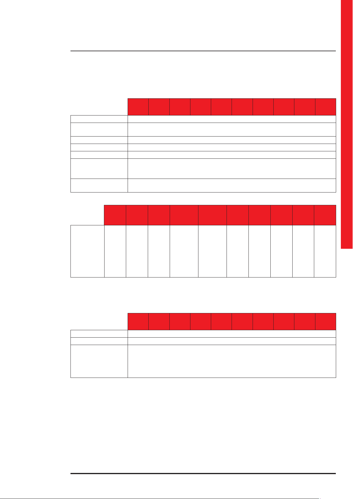
Batteries and Battery Charger Characteristics
Trimod MCS
User manual
Trimod
MCS 3
Battery type Long-life maintenance-free sealed lead-acid (VRLA); life expectancy 10 years
Unitary capacity
Rated battery voltage 240 Vdc (20 batteries 12V in series)
Type of battery charger High performance PWM, one for each power module
Recharge curve Smart Charge, advanced three-stage cycle
Battery charger
nominal recharge
current
Charging time
(EN50171)
Minimum
number of
batteries to
guarantee an
autonomy of
1 h
(EN50171) *
3 109 90
Trimod
MCS 3
battery
drawers
3 109 91
Trimod
MCS 5
8
battery
drawers
12
Trimod
MCS 5
3 109 92
Trimod
MCS 7
battery
drawers
Trimod
MCS 7
Non-modular external battery cabinets: 20 batteries 12Vdc - 94Ah
3 109 93
24 battery
(12 in the
16
EPS + 12 in
the external
cabinet 4KB)
Trimod
MCS 10
Battery drawers: 5 batteries 12Vdc - 9Ah
2.5 A max for every power module installed
Trimod
MCS 10
drawers
modular
battery
Trimod
MCS 15
3 109 94
Trimod
MCS 15
36 battery
drawers
(16 in the
EPS + 20 in
the external
modular
battery
cabinet 5KB)
Trimod
MCS 20
12 h max
3 109 95
Trimod
MCS 20
1
external
non-
modular
battery
cabinet
Trimod
MCS 30
3 109 96
Trimod
MCS 30
external
non-
modular
battery
cabinet
Trimod
MCS 40
3 109 97
Trimod
MCS 40
2
external
non-
modular
battery
cabinet
2
Trimod
MCS 60
3 109 98
Trimod
MCS 60
3
external
non-
modular
battery
cabinet
Trimod
MCS 80
3 109 99
Trimod
MCS 80
4
external
non-
modular
battery
cabinet
*1h autonomy only guaranteed for the item codes listed in the table
Features
Trimod
MCS 3
Signals and alarms Large four line alphanumeric screen, multicolour status indicator, acoustic notication
Communication ports 2 x RS 232 ports, 1 relay interface, 1 contact port, 1 SMNP module slot
Protections
Trimod
MCS 5
Electronics against overloads, short-circuit and excessive battery discharge
Trimod
MCS 7
Trimod
MCS 10
Block of functions due to the end of autonomy
Auxiliary contact for Backfeed protection
Trimod
MCS 15
In-rush limiter on start up
Trimod
MCS 20
EPO contact
Trimod
MCS 30
Trimod
MCS 40
Trimod
MCS 60
Trimod
MCS 80
55
Page 56

11. Technical data
Mechanical characteristics
Net weight
(without batteries and
power modules)
Dimensions in mm
(w x h x d)
3400 VA power
modules installed
5000 VA power
modules installed
6700 VA power
modules installed
Power module
net weight
Battery drawer
net weight
Net weight
(without batteries and
power modules)
Dimensions in mm
(w x h x d)
3400 VA power
modules installed
5000 VA power
modules installed
6700 VA power
modules installed
Power module
net weight
Battery drawer
net weight
3 110 00
Trimod
MCS 3
1 - 3 - - - -
- 1 - - 6 - -
- - - 3 - 6 9
3 110 00
Trimod
MCS 5
87 kg 90 kg 86 kg 83 kg 92 kg
13.3 kg - - - -
3 110 02
Trimod MCS 7
- - -
- 3 -
1 - 12
3 110 00
Trimod
MCS 10
105 kg 122 kg
13.3 kg -
3 110 01
Trimod
MCS 20
414 x 1370 x 628
8.5 kg
3 110 02
Trimod MCS 15
414 x 1650 x 628
8.5 kg
3 110 03
Trimod
MCS 30
3 110 04
Trimod
MCS 40
3 110 06
Trimod MCS 80
3 110 05
Trimod
MCS 60
56
3 108 08
3 110 07
Trimod MCS
Battery Cabinet
4KB
Net weight
(without batteries)
Dimensions in mm
(w x h x d)
Battery drawer weight 13.3 kg -
Weight of each 94Ah
battery
82 kg 96 kg 100 kg
414 x 1370 x 628 414 x 1650 x 628 600 x 1635 x 800
- 32.6 kg
3 106 16
Trimod MCS
Battery Cabinet
5KB
3 108 09
3 108 10
3 108 11
Trimod Battery Cabinet
94Ah
Page 57

Environmental conditions
Trimod MCS
User manual
Trimod
MCS 3
Operating temperature 0 ÷ 40 °C
Relative humidity
during operation
Storage temperature -20°C ÷ 50 °C (excluding batteries)
Noise level at 1 metre 58 ÷ 62 dB
Protection index IP 20
Operating height up to 1000 metres above sea level without derating
Trimod MCS 3 108 51 battery charger module (BCM) technical specications
Rated input voltage 230 Vac + 15% - 20%
Rated input current 19.3 A
Input Power Factor PF > 0.99
Total harmonic
distortion of the input
current
Rated output voltage 240/252 Vdc
Output voltage in
maintenance phase
Rated output current 15 Adc max
AC/DC performance >93% at max rated output current
Operating status
indications
(signalled by
multicoloured LED on
module and indications
on the display)
Trimod
MCS 5
Trimod
MCS 7
Green LED, slow ashing: recharge phase f2 and maintenance
Trimod
MCS 10
Yellow LED, fast ashing: recharge phase f1
Trimod
MCS 15
0% ÷ 95% non condensing
13.75 Vdc per battery
Green LED steady: standby
Red LED: fault status
Trimod
MCS 20
THDi < 3%
Trimod
MCS 30
Trimod
MCS 40
Trimod
MCS 60
Trimod
MCS 80
Reference directives and standards
CPSS EN 50171
Safety
EMC
Performance and test
requirements
2014/35/EU directive
EN 62040-1
2014/30/EU directive
EN 62040-2
EN 62040-3
57
Page 58

58
Page 59

Trimod MCS
User manual
59
Page 60

LEGRAND
Pro and Consumer Service
BP 30076 - 87002
LIMOGES CEDEX FRANCE
www.legrand.com
Installer stamp
Legrand reserves at any time the right to modify the contents of this booklet and to communicate,
in any form and modality, the changes brought to the same.
 Loading...