

Page 1
RFB Recessed Floor Box
Legrand/Wiremold electrical systems conform to and should be properly
grounded in compliance with requirements of the current National
Electrical Code or codes administered by local authorities.
All electrical products may present a possible shock or fire
hazard if improperly installed or used. Legrand/Wiremold electrical
products may bear the mark of a Nationally Recognized Testing
Laboratory (NRTL) and should be installed in conformance with current
local and/or the National Electrical Code.
I N S T A L L A T I O N I N S T R U C T I O N S
Installation Instruction No.: 1 002 639 R5 – Updated June 2012
Products Covered: RFB4, RFB4-CI-1, RFB4-CI-NA, RFB4-4DB, RFB4-SS
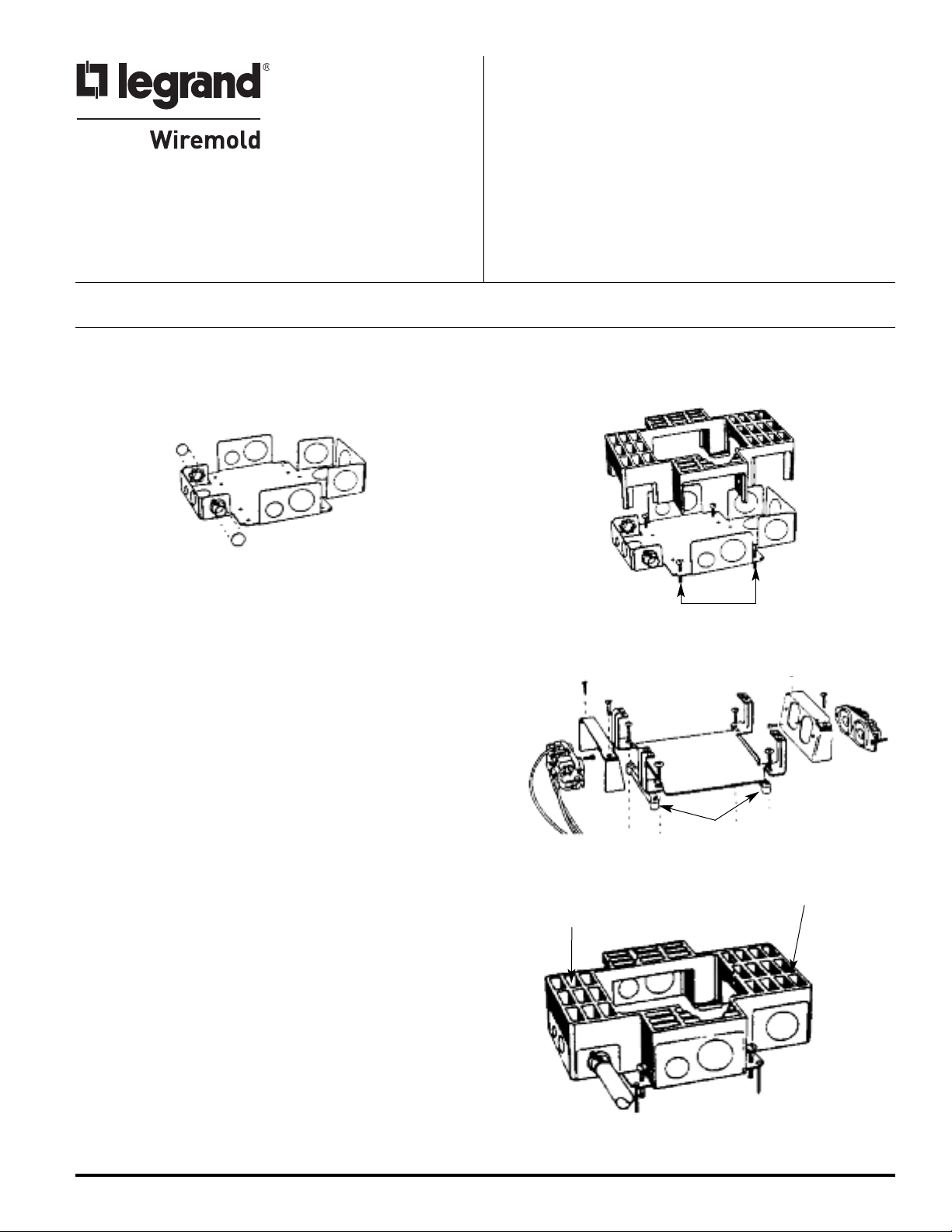
RFB4 Recessed Floor Box –
Step 1 Determine box location and conduit layout. Remove
knockouts and attach proper conduit adapters (sold
separately) to steel base.
Step 3 Insert combination bracket inside of housing. Mount to
base with four #10-24 x 5/8" [15.9mm] Phillips drive machine
screws. If compartments (A) and (B) are used for different services,
then one or both tunnel blocks must be pressed into the
combination bracket to block the passage of wires between the two
compartments. If pass-through is required between compartments
(A) and (B), tunnel blocks are not needed. Pass-through is available
only between compartments (A) and (B).
Step 4 Secure box to subfloor using wire or nails through the slot adjacent
to the adjusting screws. Once positioned, connect conduit to
adapters.
Step 5 Leave receptacle brackets in shrink wrapping and inside box until
concrete is set and receptacles are ready to be installed.
Step 6 Insert unused tunnel blocks into fingers of combination bracket.
Place brackets in box and insert mudcap on top of blocks.
Before Concrete Pour:
IMPORTANT: Please read all instructions
before beginning.
Step 2 Slip housing over base. Using the adjusting screws provided
and adjust box so that top is 1/16" [1.6mm] below screed line.
Adjusting Screws
Step 3
Tunnel Blocks
Step 4
Compartment A
Compartment B
WARNING: Pour concrete to 1/16" [1.6mm] above box
housing. Pours of 1/4" [6.4mm] or more over
box housing will make it difficult to breakout
the mudcap and cause excessive spalling.
Page 2
RFB4 Recessed Floor Box –
Step 7 Locate box and chip away concrete located in
After Concrete Pour:
mudcap. Remove mudcap
and device plates. Remove tunnelblocks from the combination bracket fingers.
Clean out any debris. If concrete does not break cleanly around preset, the
activation might not be properly supported. If edges of FloorPort
™
Series Activations
are not supported by concrete on all sides, repair of excessive concrete spalling is
required.
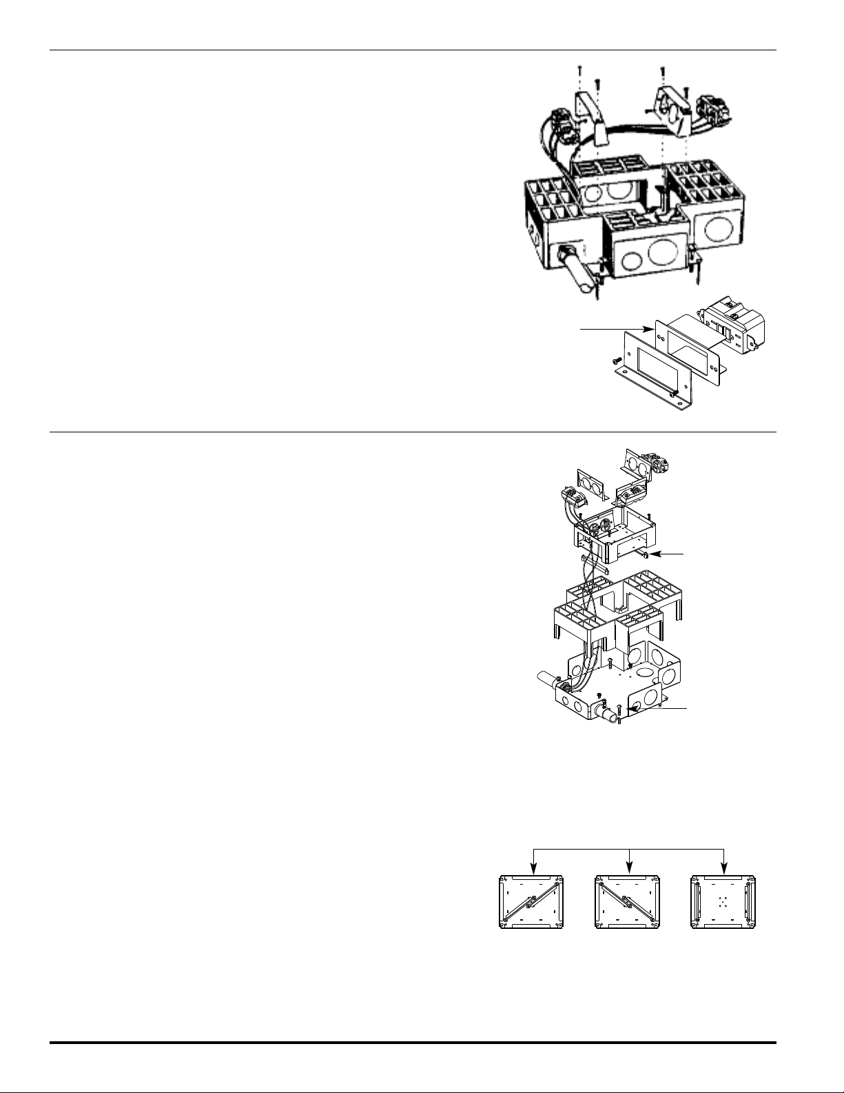
Step 8 Wire devices (not included) in accordance with the National Electrical Code or any
local code that applies. Make sure that any ground leads are connected to ground
crews. Attach the receptacle to the receptacle mounting bracket using #6-32 screw
s
provided. Attach the receptacles to the receptacle mounting brackets with two
additional screws and nuts (not provided). Attach the receptacle mounting bracket to
the combination bracket using two #10-24 mounting screws provided.
Step 9 Complete procedure by installing a FloorPort Series Activation (sold separately)
using the installation instructions provided with the unit. instructions provided with
the unit.
This box and activation are UL Listed for use with tile, terrazzo, and
carpet floors.
Use insulator provided with the following catalog numbers:
RFB-GFI, CIHT-GFI, RFB-GFI-SS, RFB-GFI-4DB.
A
Insulator
B
RFB4-4DB Recessed Floor Box –
Before Concrete Pour:
Step 1 Remove knockouts and attach conduit to base using proper conduit adapters
(not supplied).
Step 2 Slip housing over base. Using the adjusting screws provided adjust box so that
top is 1/16" [1.6mm] below screed line.
Step 3 Once positioned, connect conduit to adapters and anchor box to the subfloor by
wire or nails through the slot adjacent to the adjusting screws.
Step 4 If all four compartments are not being used for single service, tunnel blocks may
be installed to provide service isolation when feedback through wiring is not
required (see Tunnel Block Arrangements Illustration).
Step 5 Insert combination bracket inside of housing and mount to base with four #10-24
x 5/8" [15.9mm] machine screws.
Step 6 Leave receptacle brackets in shrink wrapping until concrete is set and receptacles
are ready to be installed.
Step 7 Insert unused tunnel blocks inside of box and insert mudcap.
WARNING: Pour concrete to 1/16" [1.6mm] above box housing. Pours of
WARNING: Compartments for power applications must be configured to
RFB4-4DB Recessed Floor Box –
1/4" [6.4mm] or more over box housing will make it difficult to
breakout the mudcap and cause excessive spalling.
allow either direct access or via tunneling to one of the two
grounding screws in either compartment.
After Concrete Pour:
Step 1 Locate box and chip away concrete located in mudcap. Remove
mudcap and unused tunnel blocks. Clean out any debris.
tep 2 Attach receptacles (not supplied) to the receptacle brackets, using
#6-32 screw provided. Attach the receptacles to the receptacle
mounting brackets with two additional screws and nuts (not
provided). Wire devices (not included) in accordance with the
National Electrical Code or any local code that applies. Make sure
that any ground leads are connected to ground screws before
securing receptacle brackets using #6-32 x 3/8" [9.5mm] R.H.M.S.
Step 3 Complete procedure by installing a FloorPort Series Activation
WARNING: If concrete does not break cleanly around preset,
using the instructions provided with the unit.
Tunnel Block
(See Step Four)
Adjusting Screw
Possible Tunnel Block Arrangements
the activation might not be properly supported. If
edges of FloorPort Activations are not supported
by concrete on all sides, repair of excessive
concrete spalling is required.
Page 3

RFB4-CI-1, RFB4-CI-NA Recessed Floor Box –
efore Concrete Pour:
B
Step 1 Remove conduit opening hole plugs and attach conduit to housing in accordance
with local codes.
Step 2 Align cover plate over top of housing and secure in place with four #8-32 x 3/8"
[9.5mm] machine screws.
Step 3 Using the adjusting screws supplied, adjust box so that the flat surface of the cover
plate is 3/4" [19.1mm] below the screed line.
over Plate
C
A
djusting Screws
RFB4-CI-1, RFB4-CI-NA Recessed Floor Box –
After Concrete Pour:
Step 4 Locate box and chip away concrete located in mudcap. Remove mudcap and device plates.
Clean out any debris.
Step 5 Remove wiring compartment cover by first removing the #8-32 x 3/8" [9.5mm] machine
screw and then lifting the cover out of box (a small tip screwdriver used as a lever will help
in removing cover).
Step 6 Wire devices (not included) in accordance to the National Electrical Code or any local code
that applies. Make sure that any required ground leads are connected to the ground screws
before securing receptacle brackets in place. Connect receptacles to the receptacle brackets
using the #6-32 screw provided. Attach the receptacle to the receptacle mounting bracket
with two additional screws and nuts (not included).
Step 7 Secure receptacle brackets to box by first loosening the mounting screws a few turns. Next,
position top of bracket in place and pivot the forked ends under mounting screws. Tighten
mounting screws.
Step 8 Make sure that wires in tunnel area are not kinked or pinched. Attach tunnel blocks to wiring
compartment cover to isolate one compartment from the other as required (see Tunnel
Block Arrangement Illustration). Secure wiring compartment cover to box with #8-32 x 3/8"
[9.5mm] screws.
Step 9 Complete installation by installing a FloorPort Series Activation using the instructions
provided with the unit.
This box and activation are UL Listed for use with tile, terrazzo, and carpet floors.
WARNING: If concrete does not break cleanly around preset,the activation might
not be properly supported. If edges of FloorPort Activations are not
supported by concrete on all sides, repair of excessive concrete
spalling is required.
Mounting Screws
Possible Tunnel Block Arrangements
Page 4

RFB4-SS Shallow Steel Recessed Floor Box –
tep 1 Determine box location and conduit layout. Remove knockouts and attach proper
S
efore Concrete Pour:
B
conduit adapters (not included) to steel base.
Step 2 Select internal compartments of box which are to be used for power. Service
isolation may be acquired by plastic housing. Power compartments must be
arranged adjacent to one another to utilize the “pass-around” tunneling system (see
Figure 1).
Step 3 Slip housing over base. Insert retaining bracket inside housing and secure to base
using four #10-24 x 3/16" [4.8mm] screws provided (see Figure 2).
Step 4 Adjust box so that top of housing is 1/16" [1.6mm] below screed line using the
leveling screws provided. Secure box to subfloor using wire or nails through the
slots adjacent to the adjusting screws. Once positioned, connect conduit to fittings.
tep 5 Leave receptacle brackets in plastic bags until concrete is set and receptacles are
S
ready to be installed. Place brackets in box and insert mudcap.
NOTE: Make sure proper compartments are isolated before concrete
placement as barriers must be broken out rendering the barrier
useless and possibly breaking the plastic housing
.
Figure 1
Step 7
Figure 2
RFB4-SS Shallow Steel Recessed Floor Box –
After Concrete Pour:
Step 6 Locate box and chip away concrete located in mudcap. Remove mudcap and
device plates from the box. Clean out any debris.
Step 7 Wire devices (not included) in accordance with the National Electrical Code or any
local code that applies. Make sure that any ground leads are connected to ground
screws. Connect receptacles to receptacle brackets using #6-32 x 3/8" [9.5mm]
screws (see Figure 2).Attach the receptacle to the receptacle mounting bracket with
two additional screws and nuts (not provided). Secure receptacle brackets to base
using remaining #10-24 x 3/16" [4.8mm] screws.
Step 8 Complete procedure by installing a FloorPort Series Activation (sold separately)
using the installation instructions provided with the unit.
This box and activation are UL Listed for use with tile, terrazzo, and carpet
floors.
WARNING: If concrete does not break clearly around preset, the
activation might not be properly supported. If edges of
FloorPort Activations are not supported by concrete on all
sides, repair of excessive concrete spalling is required.
Step 3
© Copyright 2012 Legrand/Wiremold All Rights Reserved
WIREMOLD
U.S. and International:
60 Woodlawn Street • West Hartford, CT 06110
1-800-621-0049 • FAX 860-232-2062 • Outside U.S.: 860-233-6251
Canada:
570 Applewood Crescent • Vaughan, Ontario L4K 4B4
1-800-723-5175 • FAX 905-738-9721
1 002 639 R5 0612
 Loading...