

Page 1
RFB2, RFB2-SS, RFB2-OG
Recessed Floor Box
INSTALLATION INSTRUCTIONS
Installation Instruction No.: 1 006 179 – September 2006
Wiremold / Legrand electrical systems conform to and should be
properly grounded in compliance with requirements of the current
National Electrical Code or codes administered by local authorities.
All electrical products may present a possible shock or fire
hazard if improperly installed or used. Wiremold / Legrand electrical
products may bear the mark as UL Listed and/or Classified and should
be installed in conformance with current local and/or the National
Electrical Code.
IMPORTANT: Please read all instructions
before beginning.
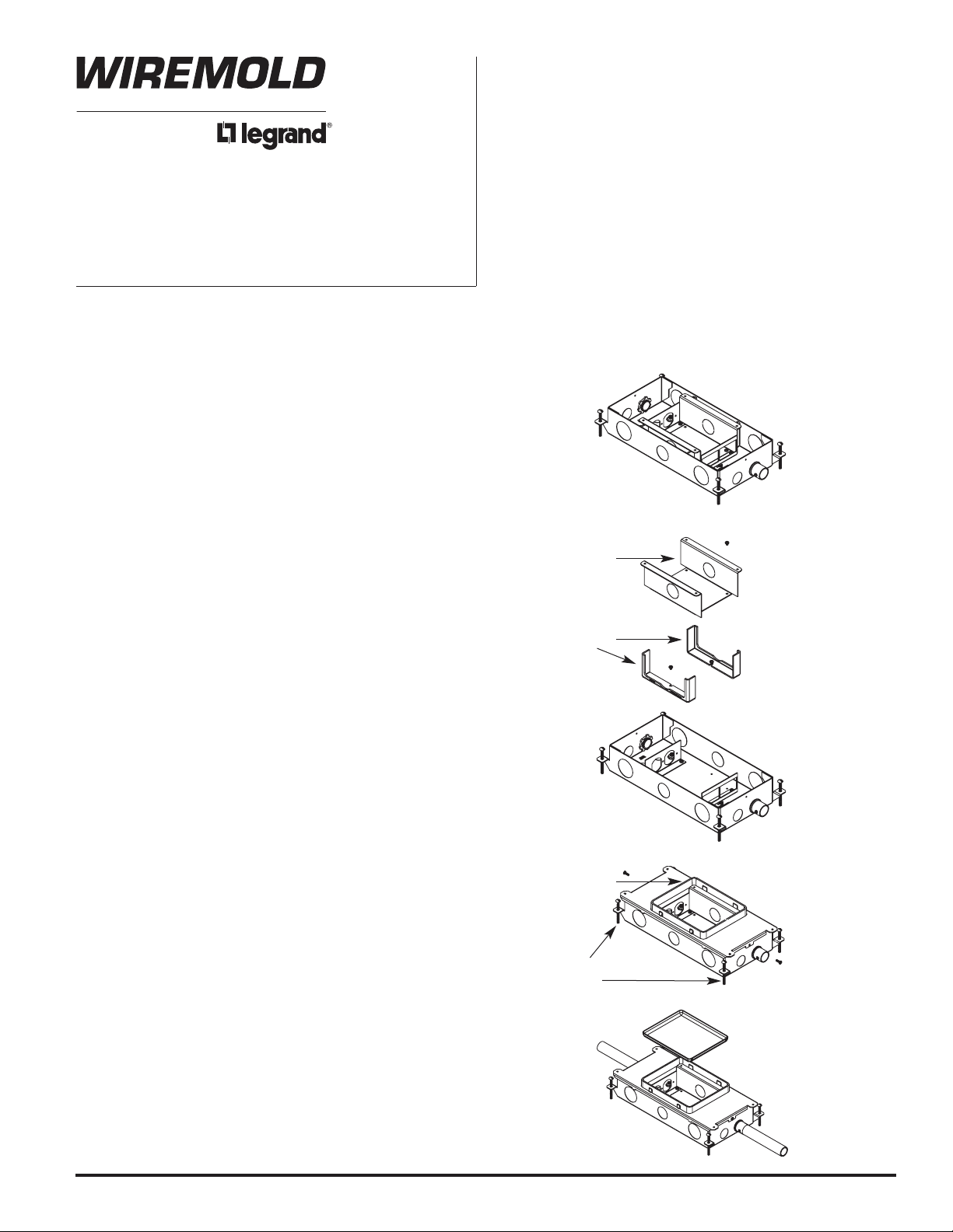
BEFORE CONCRETE POUR:
NOTE: Box is supplied with tunnel bracket, tunnel blocks
and device mounting brackets installed. If the
same service is to be used in both compartments,
it will be necessary to remove one or both of the
tunnel blocks to allow for pass-through of the
service wiring. The tunnel blocks are accessible
by removing the tunnel support. The installer may
do this either pre- or post-pour.
Step 1. Determine box location and conduit layout. Remove
box cover and desired knockouts and attach
appropriate conduit adapters, (not supplied by
Wiremold) to steel base.
Step 2. Re-attach box cover to base with (2) #8-32 x 1/2" long
screws provided.
Step 3. Adjust height of box so that the top of the black
trim ring is approximately 1/16" below the concrete
screed line.
Step 4. Secure the box to the floor using wire or other
fasteners through the holes provided in the top
cover. Once positioned, connect conduit to adapters
previously attached to box.
Step 5. Insert mud cap into top opening and press down
firmly to secure. Box is now ready for pour.
WARNING: Pour concrete to 1/16” (1.6 mm) above box
housing. Pours of 1/4” (6.4 mm) or more
over box housing will make it difficult to
break out the mud cap and cause excessive
concrete spalling.
Tunnel Blocks
Tunnel Support
Top of Plastic
Trim Ring
Adjusting
Screws
This box and activations are UL listed for use with tile, terazzo, carpet covered concrete
floors, and floors of wood construction.
Page 2
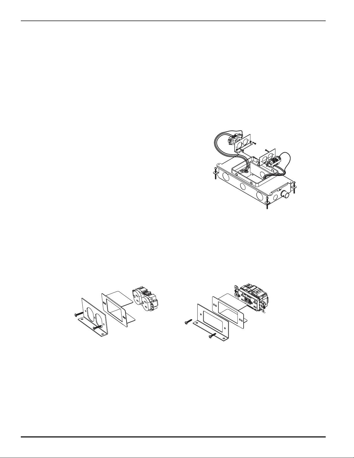
AFTER CONCRETE POUR:
NOTE: This box and activation are UL Listed for use with
tile, terrazzo, and carpet covered concrete floors,
and also wood floors.
NOTE: Use insulator provided with the following catalog
numbers, installed as shown: RFB2DP, RFB2GFI.
Step 6. Locate box and chip away concrete located in mud
cap. Remove mud cap, and clean out any debris from
inside of box. If concrete does not break cleanly around
preset, the activation might not be properly supported.
The concrete edges around the top opening of the
installed box must be smooth and level for the proper
fit of the FloorPort Activations. Remove device
brackets, and the tunnel block(s) if required to provide
for the same service in both compartments. To access
the tunnel blocks, remove the tunnel support and then
re-install after removing the required block(s).
Step 7. Wire devices (not supplied by Wiremold), making sure
that any ground leads are properly connected to
ground screws. Attach the receptacle to the receptacle
mounting bracket using the #6-32 screw provided.
Secure the receptacle to the receptacle mounting
bracket with (2) additional screws and nuts, (not
provided). Attach the receptacle mounting bracket(s) to
the base with the (2) #8-32 mounting screws provided.
Step 8. Complete procedure by installing a Wiremold FloorPort
Activation, (sold separately), using the installation
instructions provided with that unit.
Page 3
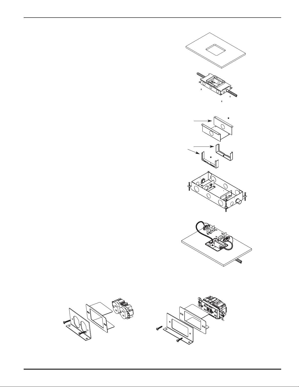
WOOD FLOOR INSTALLATION:
Step 1. Determine box location and orientation.
Step 2. Cut a 6" [152mm] x 7 1/4" [184mm] opening in
wood floor.
Step 3. Remove box cover and desired knockouts. Attach
appropriate connectors per wiring type (mc cable,
conduit, nonmetallic, sheathed, etc., not supplied
by Wiremold) to steel base. Remove tunnel block(s)
as required if power is to be used on both sides of
the box.
Step 4. Re-attach cover to box with two (2) #8-32 x 1/2" long
screws provided.
Step 5. Align plastic trim ring on top of box with opening in
floor, and secure box to underside of floor with four (4)
#8 or four (4) #10 pan head sheet metal screws, (not
supplied by Wiremold), through the four (4) holes
provided in cover.
Step 6. Wire devices, (not supplied by Wiremold), making sure
that any ground leads are properly connected to
ground screws. Attach the receptacle to the
receptacle mounting bracket using the #6-32 screw
provided. Secure the receptacle to the receptacle
mounting bracket with two (2) additional screws and
nuts, (not provided). Attach the receptacle mounting
bracket(s) to the base with the two (2) #8-32 mounting
screws provided.
Step 7. Complete procedure by installing a Wiremold
FloorPort Activation, (sold separately), using the
installation instructions provided with that unit.
NOTE: Box is supplied with tunnel bracket, tunnel blocks
and device mounting brackets installed. If the
same service is to be used in both compartments,
it will be necessary to remove one or both of the
tunnel blocks to allow for pass through of the
service wiring. The tunnel blocks are accessible by
removing the tunnel support. The installer may do
this either pre- or post-installation.
NOTE: Use insulator provided with the following catalog
numbers, installed as shown: RFB2DP, RFB2GFI.
Tunnel Blocks
Tunnel Support
Page 4

Wiremold / Legrand
U.S. and International:
60 Woodlawn Street • West Hartford, CT 06110
1-800-621-0049 • FAX 860-232-2062 • Outside U.S.: 860-233-6251
Canada:
570 Applewood Crescent • Vaughan, Ontario L4K 4B4
1-800-723-5175 • FAX 905-738-9721
1 006 179 0906
© Copyright 2006 Wiremold / Legrand All Rights Reserved
 Loading...