

Page 1
24" [610mm] Min
Center – Center
6 1/2"
[165mm] Diameter
CAUTION: Poke-Thru cannot be rotated in
hole after insertion into floor.
3" [76mm] Diameter Core Drill
3 1/16" [78mm] Actual Diameter
Push Down
#6-32 x 1/4" FHMS
(4) required
RC9 Poke-Thru Series
INSTALLATION INSTRUCTIONS
Installation Instruction No.: 1 002 947 R3 – Updated April 2005
Wiremold Electrical Systems conform to and should be installed
and properly grounded in compliance with requirements of the
current National Electrical Code, Canadian Electrical Code or
codes administered by local authorities.
All electrical products may represent possible shock or fire hazard
if improperly installed or used. Wiremold electrical products are
UL Listed to U.S. and Canadian safety standards, made for
interior use only, and should be installed in conformance with
current local and/or the National Electrical Code.
IMPORTANT: Please read all instructions
before beginning.
Products Covered: RC9STC, RC9A15TC, RC9CTC, RC9SHTC, RC9A15TC-LJB and RC9A15TCLJB25
CAUTION: Do Not operate tile stripper or resurfacing equipment over top of covers. This may result in damage to the
surface finish of the product.
Suitable for use in air handling spaces in accordance with Sec. 300-22 (C) of the National Electrical Code.
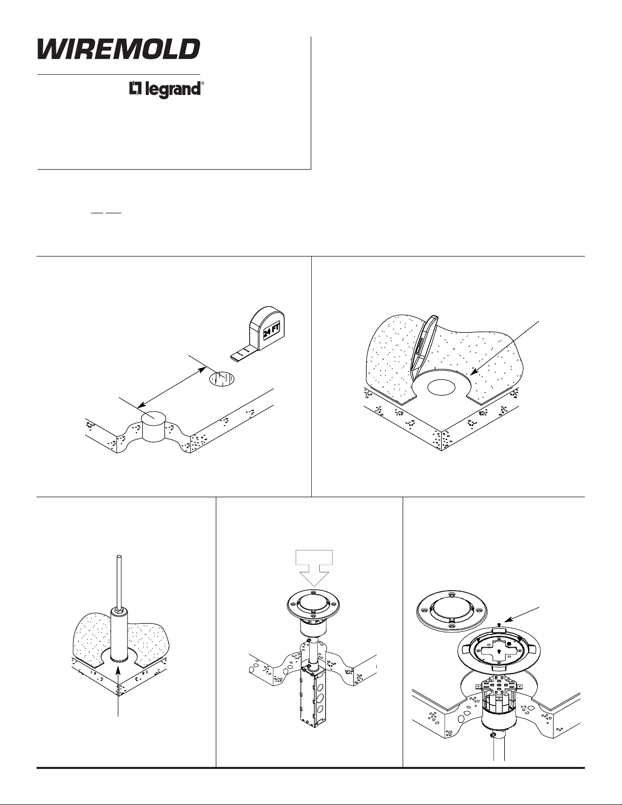
Step 1 Layout and locate position
of hole(s).
Step 3 Core drill hole.
Step 4 Stem Assembly
Catalog No. RC9STC
Insert stem into hole.
Step 5 Cover Assembly
Catalog No.: RC9CTC
Remove disposable plate
and replace with carpet/tile
flange. Install with (4) #6-32
x 1/4" [6.4mm] FHMS
Step 2 Remove 6 1/2" [165mm] section from carpet
or tile. Use template provided.
CAUTION: Holes shall be spaced a minimum of
2' [610mm] on center and not more
than one hole per each 65 sq. ft.
[6 sq. m] of floor area in each span.
NOTE: Be certain to drill hole at least 4" [102mm] from any wall or
pillar to leave enough room for poke-thru cover assembly.
NOTE: For tile installations up to a maximum of 3/4" [19.1 mm] thick.
For tile thickness greater than 3/4" [19.1mm] consult factory.
Page 2
2
Slide Cover Mounting
Screws Two #6-32
Outlet Box
Cover Plate Screw
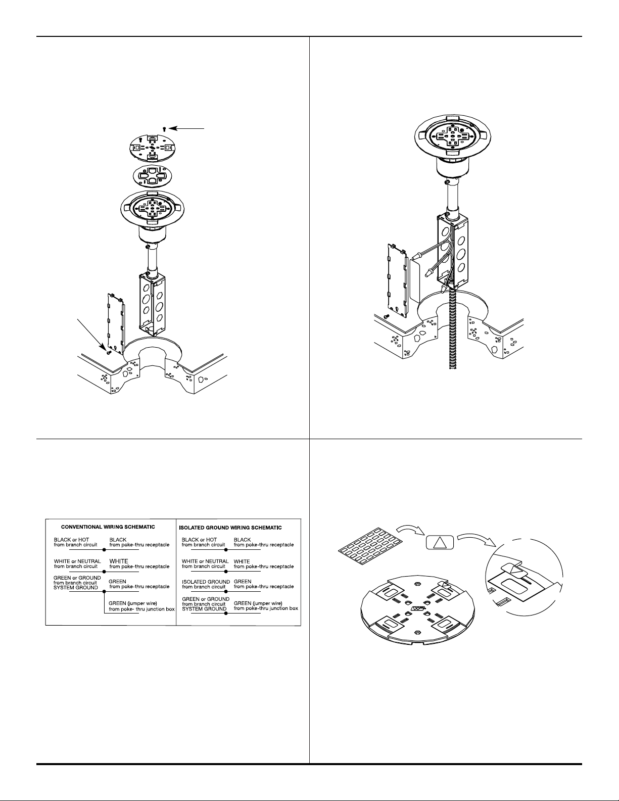
Step 6 Cat. No. RC9A15TC
Wire the Poke-Thru device (Can be completed
above floor). Refer to wiring schematic in Step 8.
Step 8 Connect Poke-Thru conductors according
to required device configuration. See
schematic below.
Step 7 Wire the POWER circuit.
WARNING: Ground wire from junction box must
be connected to SYSTEM GROUND.
CAUTION: Receptacle mounting means not grounded.
Grounding wire connection required. For isolated
ground wiring, connect ground leads to a separate
isolated grounding conductor. See NEC 250-146(d).
NOTE: The orange triangle shall only be placed on devices that
are wired for isolated ground. See NEC 250-146(d).
NOTE: When installing Cat No. RC9CTC to existing stems, apply
wiring label to the inside of the junction box cover.
COMPLETE ASSEMBLY
Step 9 If circuit is connected to an isolated ground,
apply IG icon on receptacle slide as shown.
SLIDE HOLDER ASSEMBLY
Page 3

3
CAUTION: To maintain UL Fire Classification, Slide Cover
must be replaced when communication cables
are removed. Order Cat.No. RC9SHTC.
CAUTION: Gasket must be set in place to provide scrub water
seal. Do not over-tighten Cover Mounting Screws.
Step 10 Communication Wiring
For cable pass-through, remove the egress
knockout located on the underside of the cover
Step 11 Attach Slide Cover with (2) #6 screws. Pass-
through cabling must pass through internal
gasket and data slide.
Step 12 Installation complete
Step 13 RC9 Less Junction Box
Cat No. RC9A15TC-LJB, and RC9A15TCLJB25
(Applies to installations in the City of Chicago
or other locations where local codes require
the use of a communication adapter, EMT
compression fittings, and a junction box
suitable for use in environmental air spaces.)
Follow Steps 1-11 for installation.
Pass-through
knockout
Slide Cover
Mounting Screws
(2) #6-32
Align Gasket over
Receptacle and press
bead into Flange.
Attach COM75 Adapter
(included with LJB Units)
per instructions supplied
with Unit.
Cut Slot in Gasket for
Cable pass-through
Once Poke-Thru is pushed into the cored hole,
from below, install an EMT compression fitting
(not supplied) and junction box to the conduit
system. Complete installation per NEC and
local codes.
Page 4

The RC9TC Series Poke-Thru Device is UL Listed and Classified to U.S. and Canadian safety standards to the
following conditions:
The RC9STC Poke-Thru Stem with the RC9CTC Service Head Fitting, the RC9A15TC factory assembled Poke-Thru
device, and the RC9APTC Abandonment Fitting are for use with 1-, 1 1/2-, or 2-hour rated unprotected reinforced concrete
floors and 1-, 1 1/2-, or 2-hour rated floors employing unprotected steel floor units and concrete topping (D900 Series Designs),
or concrete floors with suspended ceilings. (Fire resistive designs with suspended ceilings should have provisions for accessibility
in the ceiling area below the poke-thru fittings).
The assembled Poke-Thru stem and service fitting or the abandonment fittings will not reduce the ratings of the floor assembly
when the thickness and type of concrete (required for the specific rating) are within the specified limits and the fittings are
installed as specified:
1. Spacing – Minimum of 2' [610mm] OC and not more than one unit per 65 sq. ft. [6 sq. m] of floor area in each span.
2. Concrete – Minimum thickness of structural concrete topping of 2 1/4" [57mm] over metal deck or a minimum 3" [76mm]
thick reinforced concrete slab. Unit weight of concrete to be 110 to 155 pcf.
3. Installation – Mounted in a 3" diameter core-drilled hole in concrete per installation instructions accompanying
the fittings or abandonment fittings. For use with power circuits, data and/or telephone cables as tabulated below:
The “TC” suffix letters indicate that device may be installed on tile or carpet covered concrete floors. The “LJB” suffix
letters indicate units supplied without a junction box. The "25" suffix numbers indicate units supplied with 25 foot
receptacle leads.
(A) Maximum number of No. 12 AWG Type THHN conductors in power compartment of Poke-Thru fitting.
(B) Maximum number of 22 AWG conductors in low voltage compartment of poke-thru fitting (4-pair cables have (8)
conductors). When conductors larger than No. 22 AWG are used, the aggregate cross-sectional area of the copper
conductors shall not exceed the aggregate cross-sectional area of the 22 AWG conductors permitted in the low
voltage compartment.
For use on carpet covered and tile floors up to 3/4" [19.1mm] thick.
CAUTION: Receptacle supplied with this Poke-Thru is not suitable for direct field wiring. Contact manufacturer for
replacement. Field modifications will void UL Listing and Classification. Repalcement receptacle is limited
to this manufacturers’ Catalog No. RC9REC or RC9REC-25.
SIZE SOLID
#24 .00032 sq. in. [.20645mm2]
#22 .00050 sq. in. [.32258mm2]
#14 .00323 sq. in. [2.08386mm2]
#12 .00512 sq. in. [3.30321mm2]
#10 .00815 sq. in. [5.25805mm2]
# 8 .01296 sq. in. [8.36127mm
2
]
COPPER CROSS SECTIONAL AREA
OF COMMONLY USED CONDUCTORS
NOTE: Use above values for solid or stranded conductors.
4
RC9A15TC – 3 16
(.01536 sq. in.) [9.910mm2] (.00800 sq. in.) [5.162mm2]
RC9STC RC9CTC 3 16
(.01536 sq. in.) [9.910mm
2
] (.00800 sq. in.) [5.162mm2]
POKE-THRU SERVICE POWER COMMUNICATION
FITTING TYPE FITTING TYPE CONDUCTORS (A) CONDUCTORS (B)
Page 5

5
Page 6

Wiremold / Legrand
U.S. and International:
60 Woodlawn Street • West Hartford, CT 06110
1-800-621-0049 • FAX 860-232-2062 • Outside U.S. 860-233-6251
Canada:
570 Applewood Crescent • Vaughan, Ontario L4K 4B4
1-800-723-5175 • FAX 905-738-9721
© Copyright 2005 The Wiremold Company All Rights Reserved
Carpet Cutout
6 1/2" [165mm]
Core Hole
3 1/16" [78mm]
CAUTION: When printing copies of
this template please be
sure template is scaled
correctly and is the
correct size once it
is printed.
Carpet Cutout Template
1 002 947 R3 0405
 Loading...