

Page 1

RC3, RC7 & RC4
Receptacle Replacement
INSTALLATION INSTRUCTIONS
Installation Instruction No.: 1 003 786R1 – Updated October 2003
Products Covered: RC37REC, RC4REC2, RC37REC-25 and RC4REC2-25
IMPORTANT: Please read all instructions
before beginning.
Walker®electrical systems conform to and should be properly
grounded in compliance with requirements of the current National
Electrical Code or codes administered by local authorities.
All electrical products may present a possible shock or fire
hazard if improperly installed or used. Walker electrical products
may bear the mark as UL Listed and/or Classified and should
be installed in conformance with current local and/or the National
Electrical Code.
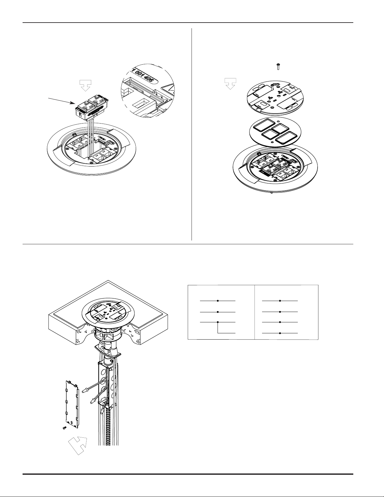
Step 1 Remove junction box cover and disconnect wires.
Step 2 Remove slide holder and scrub water gasket.
Step 3 Use screwdriver to disengage snap fingers. Move
screwdriver to the outside and pull up. Repeat on
the other side of the receptacle.
Step 4 Remove receptacle from assembly.
For RC3TC & RC7TC Series Devices
For use with: RC3TC, RC7TC, and RC4TC Series Poke-Thru Devices
CAUTION: De-energize circuit before removing
junction box cover.
Page 2
2
WHITE or NEUTRAL
from branch circuit
WHITE
from poke-thru receptacle
BLACK or HOT
from branch circuit
BLACK
from poke-thru receptacle
GREEN (jumper wire)
from poke- thru junction box
GREEN
from poke-thru receptacle
CONVENTIONAL WIRING SCHEMATIC
WHITE or NEUTRAL
from branch circuit
WHITE
from poke-thru receptacle
BLACK or HOT
from branch circuit
BLACK
from poke-thru receptacle
GREEN (jumper wire)
from poke-thru junction box
ISOLATED GROUND
from branch circuit
GREEN
from poke-thru receptacle
ISOLATED GROUND WIRING SCHEMATIC
GREEN or GROUND
from branch circuit
SYSTEM GROUND
GREEN or GROUND
from branch circuit
SYSTEM GROUND
WARNING: Ground wire from junction box must be connected to SYSTEM GROUND.
Step 5 Snap new receptacle into trim flange. Step 6 Replace gasket and slide holder with the two #6-32
screws provided.
CAUTION: Make sure bosses on receptacle match
up with cutout in the trim flange.
CAUTION: Gasket must be set in place to provide
a scrub water seal.
CAUTION: Receptacle mounting means not
grounded. Grounding wire connection
required. For isolated ground wiring,
connect ground leads to a separate
isolated grounding conductor.
See NEC250-146(d).
NOTE: Factory supplied junction box shown. Junction boxes
must be located in an accessible location. Poke-Thru
devices with an “LJB” or “LJB25” suffix are supplied
without a junction box (supplied by others).
CAUTION: Do not over tighten cover mounting screws.
Step 7 Wire up connections in the junction box. Connect
poke-thru conductors according to required device
configuration. See schematic below.
Cat. No. RC37REC
or RC37REC-25
Page 3
3
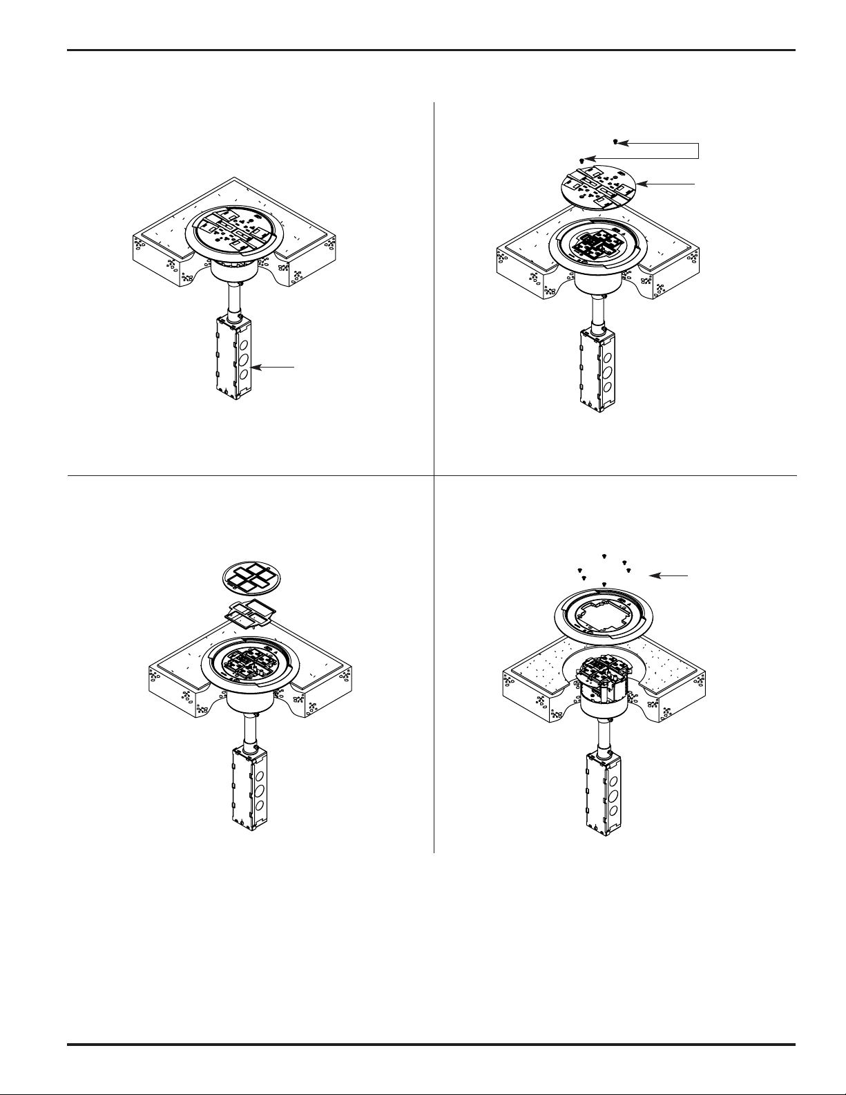
For RC4TC Series Devices
Screws
Slide Holder
Junction Box
Screws
Trim Ring
Step 1 Disconnect receptacle wiring in junction box.
Step 2 Remove two screws and slide holder.
Step 3 Remove internal gasket and gasket support.
Step 4 Remove six screws and trim ring.
CAUTION: De-energize circuit before removing
junction box cover.
Page 4

4
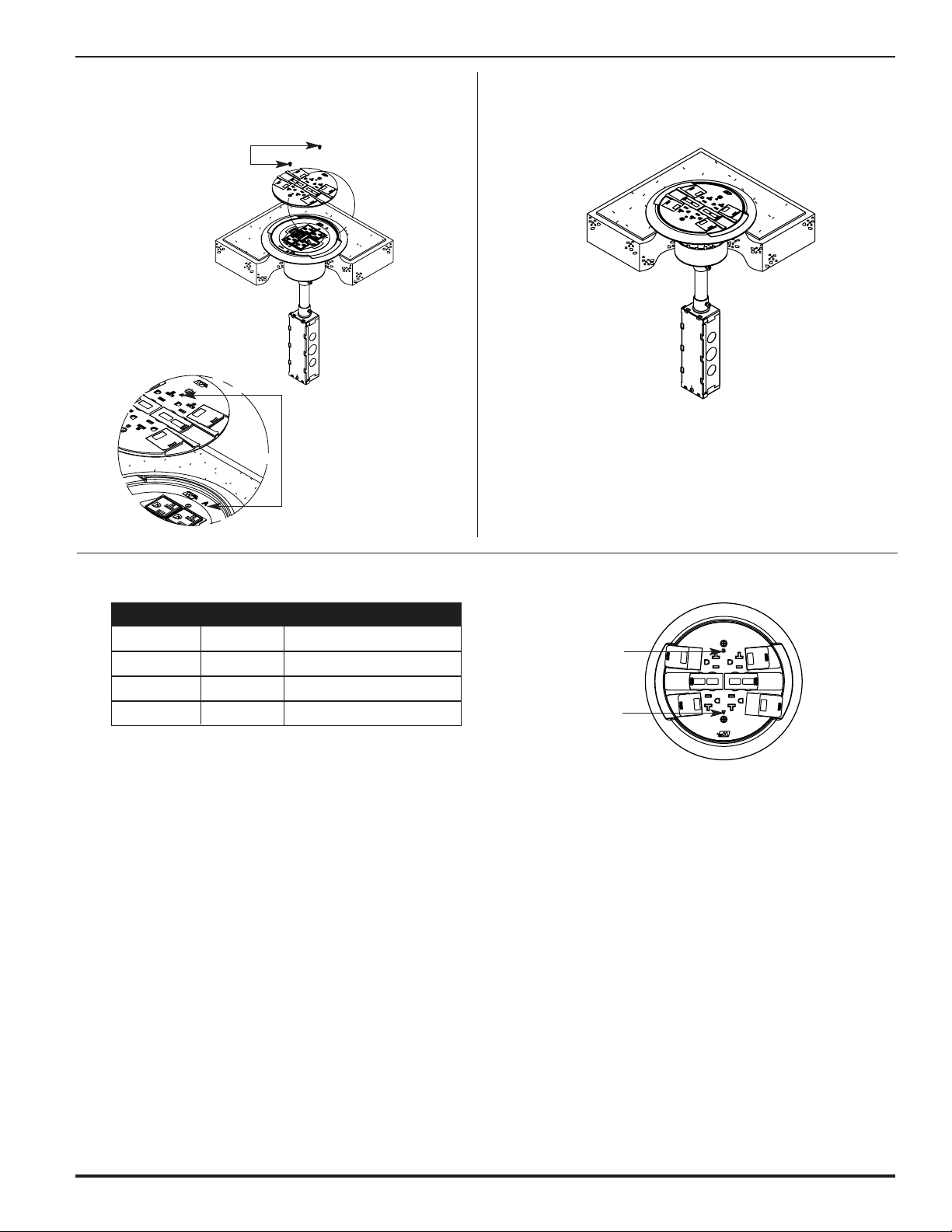
Step 5 Pull receptacles and receptacle brackets
out of poke-thru.
Step 6 Guide replacement receptacle brackets into place.
Direct wire leads through indicated opening to
junction box below.
Wire Path to
Junction Box
NOTE: Be certain to line up the trim ring with
the holes on the receptacle bracket.
The trim ring only attaches one way.
Screws Provided
IMPORTANT: Receptacle bracket slides into the
tabs shown here.
CAUTION: Gasket must be set in place to
provide scrub water seal.
Step 7 Attach trim ring to bracket with four screws provided.
Attach trim ring to receptacle bracket with two
screws provided.
Step 8 Place gasket support on receptacle bracket. Place
internal gasket on gasket support and press around
edge to seat the gasket into
the groove in the trim ring.
Cat. No. RC4REC2
or RC4REC2-25
Page 5
5
Circuit “A” Circuit “B”
Line Black Red
Neutral White White w/Blue Stripe
Ground Green Green w/Yellow Stripe
Electrical Wiring Chart
CAUTION: Letter indicators
need to be lined
up for correct
circuit identification.
CAUTION: Ground wire from junction box must be
connected to SYSTEM GROUND.
CAUTION: Receptacle mounting means not grounded.
Grounding wire connection required. For
isolated ground wiring, connect ground
leads to a separate isolated grounding
conductor. See NEC250-146(d).
Circuit “B”
Circuit “A”
Two Screws Provided
Step 9 Place slide holder on assembly lining up the “A”
and “B” indicators on the trim ring and the slide
holder. Fasten with two screws provided.
Step 10 Make electrical connections in junction box
according to wiring diagram.
NOTE: Factory supplied junction box shown. Junction
boxes must be located in an accessible location.
Poke-Thru devices with an “LJB” or “LJB25”
suffix are supplied without a junction box
(supplied by others).
Page 6

The Wiremold Company
U.S. and International:
60 Woodlawn Street • West Hartford, CT 06110
1-800-621-0049 • FAX 860-232-2062 • Outside U.S.: 860-233-6251
Canada:
850 Gartshore Street • Fergus, Ontario N1M 2W8
1-800-741-7957 • FAX 519-843-5980
1 003 786 R1 1003
© Copyright 2003 The Wiremold Company All Rights Reserved
 Loading...