

Page 1
MyHOME® Lighting Control
and Energy Monitoring Kit – MHKIT1
Technical Guide
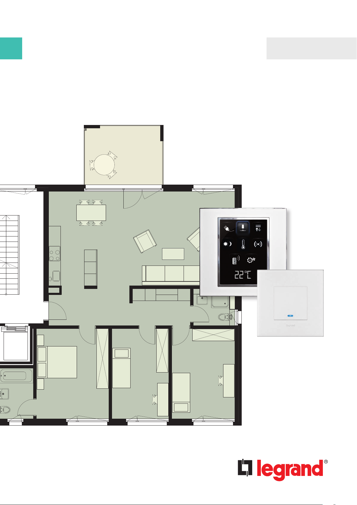
Home automation solutions
Alfresco
Dining
Room
for a residential home
Bedroom 1
Kitchen
Lounge
Corridor CupboardEntry
Bedroom 2 Bedroom 3
WC
Bathroom
0 1 3 6m
Page 2
Contents
Kit inclusions �����������������������������������������������������3
Installation configuration and placement ��������4
Kit wiring connection ����������������������������������������5
Datasheets ���������������������������������������������������������6
User Guide �����������������������������������������������������116
Warranty ����������������������������������������������������������17
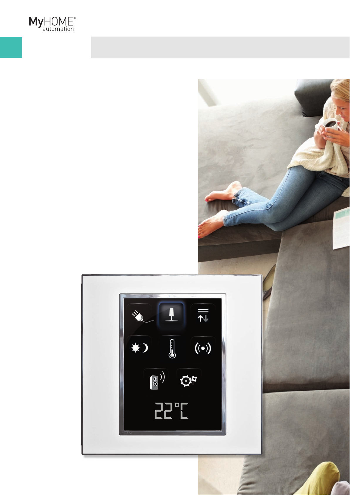
The MyHOME Lighting Control and Energy
Monitoring Kit provides a solution to control
lighting circuits, switching and dimming,
and the ability to monitor energy consumption�
It includes a 3�5" colour touchscreen for
centralised management of all functions and
easy monitoring of energy consumption�
This kit comes factory pre-programmed�
Page 3

Kit inclusions
Kit Catalogue Number: MHKIT1
MHKIT1 Contents:
■ 1 x power supply, 600mA output (Cat� No� E49)
2 3
■ 3 x trailing Edge single channel 400VA dimmer(Cat� No� F418)� To drive 3 separate
dimmer circuits (Zone 1-2-3)� Suitable for incandescent, CFL and LED fixtures
■ 1 x double channel 6A relay per channel (Cat� No� F411/2)� To drive 2 separate lights in
the ON/OFF function (Zone 4-5)
■ 5 x 1 gang switches (Cat� No� 67552)� Controls all 5 lighting channels
■ 1 x current meter (Cat� No� F520)� To monitor the main power consumption of the house
■ 1 x scenario unit (Cat� No� F420) controls 16 different scenarios from the 3�5”touchscreen
■ 1 x 3�5” touchscreen (Cat� No� 573958)� Controls and monitors every single load of
automation system, plus the scenario and energy consumption
■ 1 x 24 din module enclosure box (Cat� No� HL24S)� Allows installation of all DIN devices
in a single point for easy access
†
Functionality of the KIT:
■ Control the dimming of your lights with a dedicated dimmer switch or the 3�5”
touchscreen
■ Switch your lights on/off using a dedicated switch or the 3�5” touchscreen
■ Use the 3�5” touchscreen as a central controller to drive the Automation system
(light-dimmer-scene-energy monitoring)
■ Use a mobile device, such as a smart phone or tablet, to remotely monitor and control
the lighting, automation scenarios and your energy consumption*
*Mobile device, App and WiFi access point not included in this kit�
†
Recommend using HPM or Legrand dimmable LED fixtures�
Mobile device activation
For further details on mobile setup please contact the Legrand Customer Service team
on 1300 369 777�
Warranty
Legrand 4 year extended warranty� See page 15 for details�
Page 4
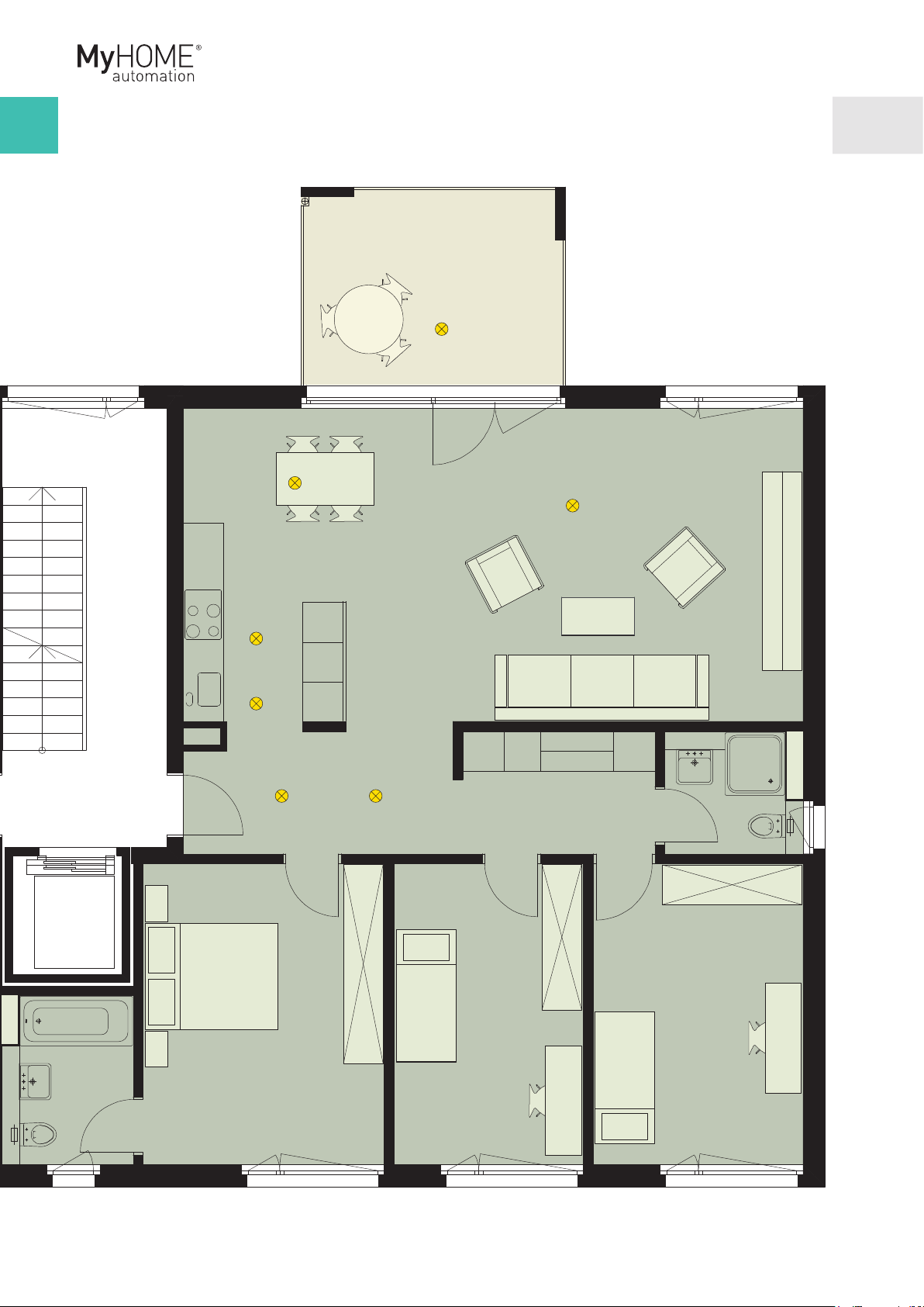
Installation configuration and placement plan
Example
Zone 1 -
dimmer
Zone 3 - dimmer
Zone 4 -
relay
Zone 2 -
dimmer
Zone 5 - relay
0 1 3 6m
Page 5
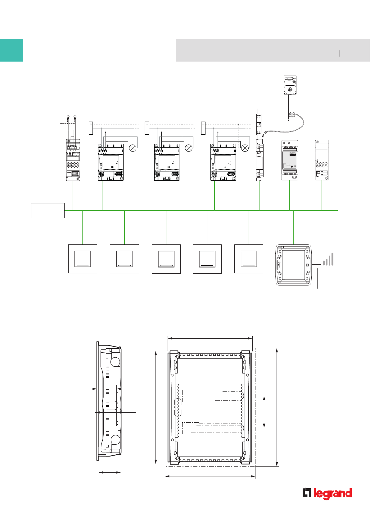
Kit wiring connection
PRI
54
SCS Cable
Cat. No. 336 904
N
L
Zone 4 & 5
Zone 1
L
N
220-240V ~ 50 - 60 Hz
110-127V ~ 50 - 60 Hz
Zone 1
250V
H
T1,6
Zone 2
Panel Board
L
N
250V
12W19
ID
200W
100W
H
T1,6
220-240V ~ 50 - 60 Hz
110-127V ~ 50 - 60 Hz
12W19
ID
200W
100W
Zone 2
F418F411/2
F418
Dimmer Dimmer SwitchDimmer
Zone 3
Zone 4
L
N
Zone 3
250V
H
T1,6
220-240V ~ 50 - 60 Hz
110-127V ~ 50 - 60 Hz
12W19
200W
100W
F418
ID
Zone 5
230 Vac
C16
Switch
N L
SCS
E49F520
Touchscreen
DEL
F420
LAN
Command Switch
The dimension of the enclosure box (CAT No. HL24S) are:
72
47.5
86.5
(1)
A
330
350
Connect CAT5/CAT6 to
your home network for
smart phone app�
(1)
(2)
B
125
(2)
Page 6
Datasheets
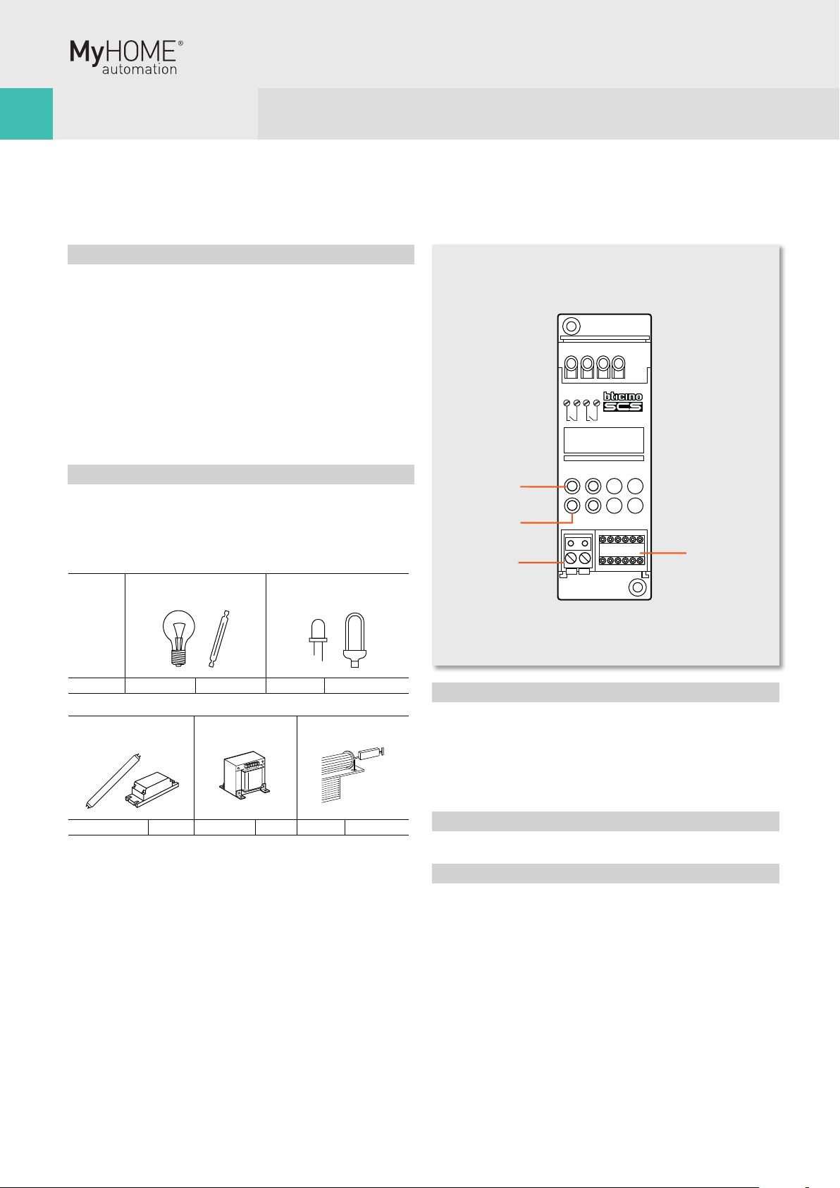
2 relay actuator in DIN module
Description
Actuator for installation in DIN rail distribution boards or
switchboards� This device incorporates two independent relays
for the activation of 2 loads, and includes local control pushbuttons for each individual load, which are only active if the
actuator has been configured� The device can be installed in a
MyHOME system and configured physically or virtually� In this
case when the PL1 and PL2 positions are configured using the
same configurator the device interlocks the relays, to which it
is possible to connect motors of rolling shutters, curtains, etc�
When installed as a component of the Lighting Management
system, specific configuration procedures are used (Plug&go,
Project&Download)�
F411/2
1 2 43
ART. F411/2
Technical features
Power supply from BUS: 27 Vdc
Operating power supply with SCS BUS: 18 - 27 Vdc
Absorption: 28 mA
Number of outputs: 2 x 6 A
Power/Absorption of driven loads:
Incandescent lamps
Halogen lamp
230 Vac 1380 W 6 A 250 W Max. 4 lamps
Linear fluorescent lamp
Electronic transformer
230 W 1 A 2 A cosφ 0.5 460 VA 460 W 2 A
Ferromagnetic
transformers
Dissipated power with max load: 1�7 W
LED lamp
Compact fluorescent lamp
Motor reducers for
rolling shutters
(1)
Operating temperature: (-5) – (+45) ºC
Number of outputs: 2 x 6 A
NOTE: (1) The dissipated power indicated is that corresponding to the
device with all the relays loaded at the maximum load�
With lower loads also the dissipated power is lower and may be calculated
by means of the following formula: P(mW)=140+400*N+10*(Ic1+Ic2)
P: dissipated power in mW, N: no� of loaded relays, IN: load current
corresponding to the N relay�
C1 C2
4
3
2
Legend
1� Configurator socket (attention, it must only be used in
MyHOME systems with physical configuration)
2� BUS
3� LED
4� Push-button
Dimensional data
Size: 2 DIN modules
MyHOME Configuration
When installed in a MyHOME system, the device may be
configured in two ways:
■
PHYSICAL CONFIGURATION, by connecting the physical
configurators to their sockets�
■ VIRTUAL CONFIGURATION, by connecting the system to the
PC using the Kit or the Web server� The Virtual configurator
software must be installed on the PC�
1
Page 7

Diagram for the control of a 230 Vac motor with 2 windings
Diagram for the connection of lighting devices
F411/2
6 7
Physical configuration
The actuator performs all the basic operating modes that can be
configured directly on the control� Moreover further operating
modes with the configurator in position M of the same actuator
are listed in the table below�
Possible function Configurator in M
Timed stop for motors� The device deactivates after the time set has elapsed
(1)
�
This mode is only operative if LP1=LP2
(same configurators), i�e� with the two relays
interlocked
Master actuator with OFF control delayed on
the corresponding Slave actuator� With the
OFF control the Master actuator deactivates;
the Slave actuator deactivates after the time
set with the configurators has elapsed
(2)
�
This model is only operative if PL1≠PL2�
Actuator as Slave� Receives a control sent by
a Master actuator with the same address�
Push-button (ON monostable) ignores Room
and General controls�
Configurator Time (minutes)
No configurator 1
1 2
2 5
3 10
4 infinite or until the next
5 20 sec
6 10 sec
7 5 sec
8 15 sec
9 30 sec
none - 9
none - 4
SLA
PUL
control
(1)
(2)
Virtual configuration
Using the Virtual configurator software it is possible to perform
all the functions listed below:
■ light actuator
■ rolling shutter actuator
Lighting Management configuration
When installed in a Lighting Management system, the device can
be configured in the following ways:
■ Plug&Go (see the dedicated technical guide)
■ Project&Download,
Using the Virtual configurator software it is possible to perform
all the functions listed below:
■ Light actuator
Wiring diagrams
A
PL
N
L
1 2 43
ART. F411/2
C1 C2
1
3
2
4
MIN 3m
N
L
F411/2 actuator
M
G1
G2
P
L
L N
M
L1 L2
M = motor in AC
with 2 windings
L1-N = clockwise rotation
L2-N = anticlockwise rotation
L N
N
L
L
P
2) The value of the configurator listed in the table defines the
final time, after which the actuator disables its own slave�
Configurator Time (minutes)
No configurator 0
1 1
2 2
3 3
4 4
Page 8

Datasheets
Bus meter with 3 inputs for toroids
Description
The SCS device measures currents and voltages of separate lines
(up to 3), connecting maximum three toroids to the appropriate
inputs (one toroid, item 3523 supplied as standard)�
The meter processes and saves the following variables:
■ instantaneous power in W;
■
total energy accumulated in Wh�
The device has an internal memory that allows saving the
following information:
■ cumulative energy on an hourly basis for the last 12 months;
■ cumulative energy on a daily basis for the last 2 years;
■
cumulative energy on a monthly basis for the last 12 years�
In order to allow the device to archive consumption information,
the system must be fitted with a device capable of supplying
current date and time information (e�g� Touchscreen)� If
this information is not available, the meter will be unable to
archive the data, and will continue calculating the values of the
instantaneous variables (power)� The space requirement for
the device is equal to 1 DIN module� The device is provided with
socket for 5 configurators: A1, A2, A3-Ta, A3-Tb, A3-Tc�
Front view
5
F520
1
2
3
Technical features
Operating power supply with SCS BUS: 18 - 27 Vdc
Absorption: 35 mA max
Rated current: 16 A
Maximum current: 90 A
Operating temperature: 5 – 40 ºC
Dimensional data
Size: 1 DIN module
4
Top view
6
1
Legend
1� 230 Vac connection
2� Push-button for the deletion of cumulative energy data
3� Configurator sockets closing door
4� SCS/BUS connection
5� User interface LED, SEE TABLE
6� Ta, Tb, Tc connectors for toroids, item 3523
Page 9

F520
8 9
Configuration
The device can be configured by connecting the physical
configurators to the correct sockets (Physical configuration)�
The device is provided with socket for five configurators:
■ A1 for the hundreds
■ A2 for the tens
■ A3 Ta for the units
■ A3 Tb for the units
■ A3 Tc for the units
The combination of the configurators defines:
■ A1/A2/A3-Ta address of meter A
■ A1/A2/A3-Tb address of meter B
■ A1/A2/A3-Tc address of meter C
The maximum number of addresses is 255�
WARNING: The A3-Ta configurator cannot be zero, differently
from configurators A3-Tb and A3-Tc, which can have a zero value
(if the corresponding input is not managed)� The meter must be
installed as close as possible to the power supply, to ensure a
high BUS voltage, and enable correct management of memory
savings in case of voltage cut� If the supply voltage is insufficient
(below 21 Vdc), the meter will cause the green LED to flash to
signal the installation error� The device will work regularly, but
will not guarantee correct saving and recovery of data in case of
BUS failure�
Procedure for the deletion of the cumulative energy data:
1 Press the key; after 20 seconds the orange LED flashes quickly;
release the key�
2 All the cumulative energy data are reset�
LED notifications based on the status of the power meter
Wiring diagrams
Connection of the meter to the bus, the line, and the toroid
230 Vac
C16
N L
BUS
Device status LED
Normal operation GREEN
BUS problems (BUS voltage insufficient, or
voltage drop detected)
Installation error (230 Vac not detected)
Configuration error
No configuration
GREEN flashing
500 ms/500 ms
RED flashing
100 ms/900 ms
ORANGE flashing
irregularly on GREEN
ORANGE flashing 128
ms/128 ms on GREEN
Page 10

Datasheets
Scenario module
Description
This device allows you to manage scenarios for Automation,
Sound system and Temperature Control systems which have
been created, modified and activated using different devices of
the Automation system� Up to 16 scenarios may be saved in the
scenario module, with up to 100 controls each� The scenarios
can also give door entry and Video door entry controls for onefamily systems to switch on the staircase lights and open the
door lock� If installed in large systems with interface item F422
in logical expansion, the module can save automation controls
for the system where it is installed� On the front cover of the
item there are two keys and two LED� The first push-button
(padlock) locks or unlocks the programming procedure avoiding
involuntary operations such as cancelling the scenarios and the
corresponding LED indicates the status: green programming
possible, red programming blocked, orange
The second push-button (DEL) cancels all the scenarios, the
LED underneath indicates that the cancellation has taken place
or that the device is performing the learning procedure�
temporary block�
F420
DEL
6
5
1
2
Technical features
Power supply from SCS BUS: 27 Vdc
Operating power supply with SCS BUS: 18 - 27 Vdc
Absorption: 20 mA
Operating temperature: 0 – 40 ºC
Size: 2 DIN modules
4 3
Front view
Legend
1� Scenario cancellation push-button
2� Scenarios/learning reset LED
3� Configurator socket
4� BUS
5� Programming status LED
6� Lock/unlock programming push-button
Page 11

F420
Configuration
The combination of the scenario module with a control device
is ensured by assigning to both items the same address� This is
identified by the configurators with a numeric value for position
A = 0-9 and position PL = 1-9� When using a Touchscreen,
the address of the scenario module must be specified during
programming, using the Tidisplay software� Several scenario
modules may be installed in one system, allocating a different
address to each module�
Scenario programmer
In order to program, change or cancel a scenario, it is necessary
to enable the programming mode of the Module item F420 so
that the status LED is green (press the lock/unlock key on the
Scenario Module for at least 0�5 seconds); continue with the
following operations:
1) press one of the four control keys the scenario should be
associated to
flashing;
2) set the scenario using the corresponding controls for the
various
Automation, Temperature control, Sound system, etc�
functions;
3) Confirm the scenario by quickly pressing the corresponding
key on the control to exit programming mode;
4) to change or create new scenarios to be linked to the other
keys, repeat the procedures starting from point 1�
To call a set scenario just press its push-button on the control
quickly� If the module does not receive any input for 30 minutes
from the start of the learning procedure, programming will
automatically be interrupted� To cancel a scenario completely,
keep the corresponding push-button pressed for about ten
seconds� To erase the entire memory keep the DEL push-button
on the Scenario module pressed for 10 seconds, the yellow "reset
scenarios" LED flashes quickly� Once the operations have been
performed lock the programming by pressing the lock/unlock
push-button for at least 0�5 seconds, so that the corresponding
LED becomes red�
for 3 seconds� The corresponding LED starts
10 11
key 1
LED key 1-3
key 3
NOTES:
Inside the system itself one Scenario module can be programmed
at a time as the other devices are temporarily locked; during this
phase the “programming status” LED becomes orange signalling
the temporary Lock� During the learning procedure and when
there are timed controls or group controls, the Scenario module
does not save events for 20 seconds� You must thus wait before
continuing with creating the scenario� During the scenario
learning procedure only the changes of status are saved� The
scenario module should be configured with a different A and PL
address from that of an actuator� Use A=0 and PL=1 to 9, which
cannot be used by actuators� If the configuration is wrong the
Programming status LED flashes ORANGE� In case of "virtual"
configuration the LED flashes RED�
key 2
LED key 2-4
key 4
Page 12

4
2
3
5
1
Datasheets
Basic control for 2 independent loads
067552
Description
Two-module, push mounted and lowered special control with
4 push-buttons and 4 LEDs� The device can control one single
actuator for single or double loads, or two actuators for single or
double loads, independent from each other�
The device may be installed in a MY HOME system and can be
configured both physically and virtually, or as a component of
the Lighting Management system, using specific configuration
procedures (Plug&go, Push&Learn, Project&Download)�
Technical features
Power supply from SCS BUS: 27 Vdc
Operating power supply with SCS BUS: 18 – 27 Vdc
Absorption with maximum LED intensity: 6 mA for H4652/2
and 067552
8�5 mA for L4652/2
and AM5832/2
Dimensional data
Size: 2 push mounted modules
Dimensional data
When installed in a MY HOME system, the device may be
configured in two ways:
- PHYSICAL CONFIGURATION, by connecting the physical
configurators to their sockets�
- VIRTUAL CONFIGURATION, by connecting the system to the PC
using the 3503N Kit or the web server� The Virtual configurator
software must be installed on the PC
Lighting Management configuration
When installed in a Lighting Management system, the device can
be configured in the following ways:
- Plug&Go (see the dedicated technical guide)
- Push&Learn
- Project&Download,
Using the Virtual Configurator software it is possible to perform
all the functions listed below:
- double light control
- double CEN control
- double CEN PLUS control
- double AUX control
For more information on the functions see the glossary before
the Technical sheets chapter�
1
5
4
A
PL/PF
M
LIV1/AUX
LIV2
SPE
I
7
Legend
1� LED
2� Upper push-button
3� Lower push-button
4� LED
5� Push-button for LED adjustment/exclusion
6� Configurator socket (attention, it must only be used in
MyHOME systems with physical configuration)
7� BUS
LED adjustment
2
3
6
PUSH t > 2 s
DEFAULT
60%
30%
0%
100%
Page 13

067552
Configuration
12 13
Possible function
Combination of key covers used/Configurator in M1 and M2
1 Function 2 Functions
ON control ON –
OFF control OFF –
Timed ON control
2
) 1 – 8 –
Dimmer - ON control (upper key)
OFF (lower key) + adjustment
Cyclical ON-OFF control + adjustment
1
) – 0/I
1
) no configurator –
UP/DOWN rolling shutter to end of stroke –
Monostable rolling shutter UP/DOWN – M
Bistable rolling shutter up-down movement�
– 6
Blades adjustment if the pressure time is less
than 1�5 s� Up-down to the end of travel if the
control is pressed for more than 1�5 s�
Push-button (ON monostable) PUL –
Activation of scenarios managed by the
programmer MH200N
3
)
– CEN
Time (minutes)
– 6
Push-button (ON monostable) PUL –
Activation of scenarios managed by the pro-
– CEN
grammer MH200N3)
Configurator Time (minutes)
Virtual configuration
Using the Virtual Configurator software it is possible to perform all the
functions listed below:
- double scenario control
- double CEN control
- double scenario PLUS control
- double CEN PLUS control
Page 14

Datasheets
SCS Dimmer
Technical features
F418
Halogen
lamps
LED dimmer
lamps
Compact CFL
dimmer lamps
220 – 240 Vac 200 W 0,9 A 200 W 0,9 A 200 W 0,9 A
110 – 127 Vac 100 W 0,9 A 100 W 0,9 A 100 W 0,9 A
■ Product tested using main brands of lamp
■ NO connection mixed loads
■ NO installation of several dimmers side by side
■ NO installation of a dimmer side by side with a power supply
Wiring diagrams
L
N
12W19
T1,6H 250V
ID
F418
220-240V ~ 50 - 60 Hz
200W
110-127V ~ 50 - 60 Hz
230V
C16
100W
H 250V
T1,6
F418
220-240V ~ 50 - 60 Hz
110-127V ~ 50 - 60 Hz
12W19
ID
200W
100W
BUS SCS
■ Green LED = load voltage OFF
■ Red LED = load ON
■ Flashing LED = load fault
T1,6H 250V
F418
12W19
220-240V ~ 50 - 60 Hz
110-127V ~ 50 - 60 Hz
ID
200W
100W
ATTENTION: when replacing faulty fuses always disconnect the
supply voltage (open the main switch)�
Page 15

PRI
E49
Power supply
Warning
During the operation of electric devices powered by the electric
power line, some parts may be subjected to dangerous voltage
levels� The installation and assembly of the device must be
performed in accordance with the following installation rules:
■ the power supply must only be installed and assembled by
qualified personnel;
■ the power supply must only be installed inside switchboards
suitable for DIN devices;
■ the device is only suitable for indoor installation;
■
the device must be kept away from water drips and sprays�
■ an omnipolar switch with minimum 3mm distance between
contacts must be installed near the power supply;
■ the above described switch is to be used as the device for
disconnecting the power supply from the power line;
■ ensure that during the assembly of the devices the power
supply is not connected to the power line;
■ before powering the system, check the cable connections,
and ensure that the line voltage is compatible with the power
supply;
■ the installation must be completed in accordance with current
installation rules� Improper use of any items may compromise
their safety�
14 15
PRI: 220 – 240 V~
200 – 190 mA
50/60 Hz
SCS
Technical features
PRI (AC power supply input)
■
Rated voltages: 220 – 240 V
■ Rated currents: 200 – 190 mA
■ Nominal working voltages: 187 – 265 V
■ Nominal working frequencies: 50 – 60 Hz
■ Power consumption at full load: 21�5 W max
■ Power consumption: 5�3 W max
■ Performance at full load: 80 % typ�
■ Stand-by consumption: less than 1 W
■ Operating temperature: 5 – 40 ºC
■ Integrated fuse (PRI side): F1 T2A 250 V
SCS
■
Rated voltage: 27 V +/– 100 mV
■ Rated current: 0 – 0,6 A
■ Rated power: 16,2 W
27 Vdc
600 mA
Legend
Green LED - power supply on
Red LED - output current overload
Page 16

User Guide
Scenarios
Lets you activate scenarios that have been previously stored in one or more “scenario units”
and “scenario modules” of your MyHOME system�
Touch the scenario icon �
The display will show the page where you can find the scenarios you can activate�
NIGHT
Scenario 1
Scenario 2
Touch the icon to activate the scenario�
Scenario 1
This command lets you activate a scenario of the Scenario Module�
Furthermore, when you touch the icon , new icons will appear which will allow you to cancel or
programme a new scenario according to the functioning mode of the Scenario Module�
If the icon is not displayed, the scenarios module is blocked.
Creating a new scenario
1 2 3
1� Touch the icon to start a new scenario programming procedure�
2� Prepare your scenario by adjusting the light level of the dimmer and the lights (on or off)�
3� Return to the touch screen and touch the scenarios
4� Touch the icon to end programming�
5� Touch the icon to return to the menu of the scenarios programmed by you�
Removing a scenario
1
1� Touch the icon to remove a scenario programmed by you�
Page 17

Warranty
16 17
4 year extended warranty
Legrand understands the importance of having dependable products that work efficiently and effectively thus they offer a 4 year
extended warranty on the MyHOME Lighting Control and Energy Monitoring kit. When you buy this kit you can be certain that
the product lives up to the high standards of Legrand and that if in the unlikely event there is a problem with your kit, it will be
repaired by a fully qualified and experienced Legrand technician.
HPM Legrand will honour all statutory guarantees that you as a consumer are entitled to rely upon under the Australian Consumer
Law against a manufacturer including a guarantee that any products HPM Legrand has manufactured or imported/ the products
which are described in this Instruction Manual (Products) are of acceptable quality�
To make a claim under any statutory guarantee or other warranty you should first contact the supplier, contractor or retailer from
whom you purchased the Products�
1. HPM Legrand (“we” or “us”) has given each Purchaser who is a Consumer (“you”) a warranty against defects in its Products�
2. As a Consumer you are entitled to the benefit of the Warranty and should read and understand its terms� In addition for the
purposes of the Australian and New Zealand Consumer Laws, we note the following:
(a) Our contact details for the purpose of any claims made under the Warranty are below:
AUSTRALIA ONLY NEW ZEALAND ONLY
Legrand Australia Pty Ltd HPM Legrand New Zealand Ltd
Nexus Industry Park 106-124 Target Rd
Bldg 4, 43-47 Lyn Pde GLENFIELD AUCKLAND 0627
PRESTONS NSW 2170 0800 476 009
1300 369 777 nz�sales@hpmlegrand�co�nz
sales�orders@hpmlegrand�com�au
(b) Any claim under the Warranty must sent in writing to the following address:
AUSTRALIA ONLY
Warranty Claims Officer – Consumer Products Warranty Claims Officer – Consumer Products
Legrand Australia Pty Ltd HPM Legrand New Zealand Ltd
Nexus Industry Park 106-124 Target Rd
Bldg 4, 43-47 Lyn Pde GLENFIELD AUCKLAND 0627
PRESTONS NSW 2170
(c) If we accept your claim under the Warranty we will reimburse all your reasonable expenses in making and pursuing the claim,
including the cost of reimbursement of any defective Products returned in the ordinary course to us at the address above by post
or other agreed means� Any such claim must be made within 14 days of your receiving notice of our acceptance of your claim
and include any necessary supporting documentation or invoices�
3. As a Consumer you have rights under the Australian and New Zealand Consumer Laws and may have rights under other
applicable laws which cannot be excluded, restricted or modified� Those rights are in addition to any rights you have under the
Warranty�
4. Our goods (which we refer to in the Warranty as the Products) come with guarantees that cannot be excluded under the
Australian and New Zealand Consumer Laws� You are entitled to a replacement or a refund for a major failure and for
compensation for any other reasonably foreseeable loss or damage� You are also entitled to have the goods repaired if the goods
fail to be acceptable quality and the failure does not amount to a major failure�
NEW ZEALAND ONLY
Page 18

Notes
Page 19

18 19
Page 20

0 1 3 6m
Corridor CupboardEntry
Bedroom 1
Bathroom
Bedroom 2 Bedroom 3
Kitchen
Alfresco
Dining
Room
HPM Legrand Australia
Building 4, Nexus Industry Park
Lyn Parade, Prestons NSW 2170
Tel: 1300 369 777
www�legrand�com�au
HPM Legrand New Zealand
106-124 Target Road, Glenfield
Auckland 0627 New Zealand
Tel: 0800 476 009
www�legrand�co�nz
04_2014 LE07374AAA
 Loading...