

Page 1
REV DESCRIPTION INT: REV. DATE APPROVED
Center Fold
1 ECO# C01429 MJS 9/7/05 CG
2 ECO# 02412 DR
TITLE BOX PAGE ONLY.
DO NOT MAKE FILM • DO NOT PRINT
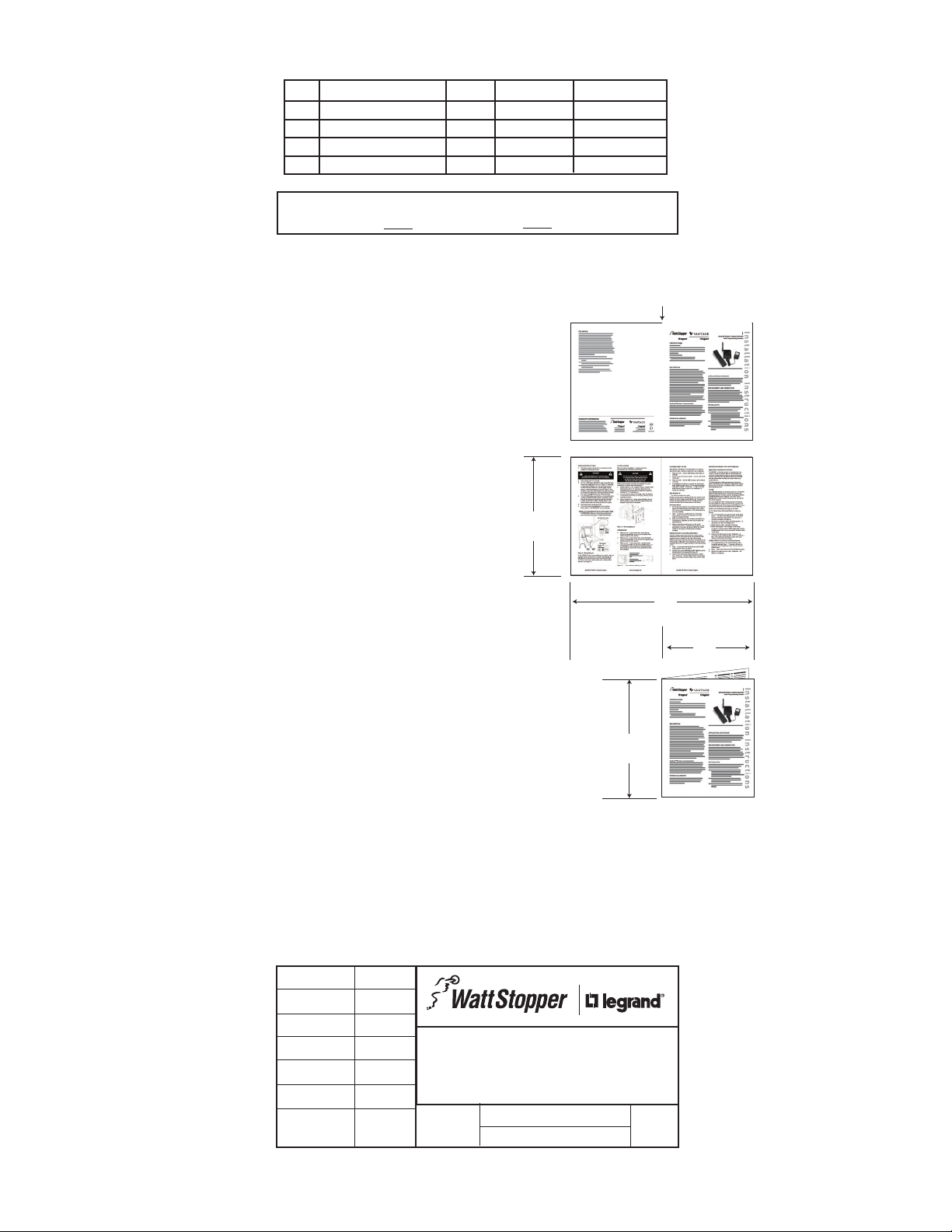
MATERIAL: White 16lb (60g/m sq), uncoated, prefer recycled stock
Ink: Black
Print Two Sides, 2 sheets 8.5” (Wide) x 11” (High),
stapled upper left corner
OR
Print Two Sides, 1 sheet 11” x 17”
folded to 8.5” x 11”
11”
431.8mm
279.4mm
11”
17”
Front PageBack Page
Inside Right PageInside Left Page
215.9mm
8.5”
MRx###
MRx###
MRx###
Front of Sheet
Back of Sheet
4-page
booklet
fold
IF YOU HAVE ANY QUESTIONS REGARDING SPECIFICATIONS OR REQUIRE
ADDITIONAL FILE FORMATTING, PLEASE CONTACT Mary Jo Sowinski.
Phone: 408-486-7511
Email: maryjo.sowinski@wattstopper.com
All information in this drawing is the property of Watt Stopper/Legrand
and cannot be copied or used without the written approval of
DRAWN BY
PLM
MARCOM
ENGINEERING
QA
TITLE BOX PG
REVEL
SCALE 1:1
Watt Stopper/Legrand.
SANTA CLARA, CALIFORNIA
Title: MRHC3/MRRC3 Installation Instructions
Drawing #:
05813
Orig. Drawing Date: 28 JUL 05
Revision Date: 28 SEP 07
REV. #:
2
Page 2

SPECIFICATIONS
UL and cUL Listed
Input Voltage ............................. 12-24VDC, 200mA minimum
Control Inputs ...............3-24VDC, 33ms hold time minimum
Output ............................................24VDC, 150mA maximum
AC-DC adaptor (provided)
Input ...............................................................120VAC, 60Hz
Output .......................................................... 24VDC, 200mA
DESCRIPTION
The MRHC3 and MRRC3 Scene Interfaces offer Top Dog™
wireless network interconnectivity to common electronic
control devices. With this interconnectivity, house and
room scenes are invoked based on inputs from the
external control device. Application examples include
alarm systems, astronomic time clocks, motion sensors
and garage doors integrated with the wireless network to
execute house and room scenes.
MRHC3 and MRRC3
House and Room Scene Inerfaces
House or Room
Removable
Terminal
Block
Scene Interface
Status LED
POWER FAIL MEMORY
After a power failure, all wireless devices automatically
return to the state that they were in immediately prior to loss
of power. All configuration and scene control information is
preserved.
Power Supply
I n stallation Inst r u c t i o n s
TOP DOG™ WIRELESS COMMUNICATION
Wireless devices use radio signals to communicate with
each other to control lighting and other types of electric
loads in selected areas. These wireless devices use the
900MHz band for high-speed control communication. Using
the “frequency-agile” Top Dog™ technology, these wireless
devices avoid interference with other 900MHz devices, such
as cordless phones and baby monitors.
OPERATION
The scene interfaces can be setup in one of two operating
modes to accept either maintained or momentary inputs.
They can initiate scenes based on active high, active low,
maintained or momentary control signals. For momentary
applications, a minimum hold time of 33ms is required so
the scene interface can process the change-of-state. The
scene assignments are fixed and cannot be changed.
Mode A, typically used with momentary control signals,
uses scenes 6 and 8 for inputs 1 and 2. Input 3 invokes the
house or room on/off scene of a controller paddle.
Mode B, typically used with maintained control signals,
uses scenes 6, 7, 8 and 9 for inputs 1 and 2. Input 3 on the
MRHC3 invokes the house “panic” scene, and on the MRRC3
it can be used to inhibit execution of scenes bound to the
other inputs.
The MRHC3 interface is a house level scene controller.
Please refer to Table 1 and Table 2 for more information
about its operating modes.
The MRRC3 interface is a room level scene controller.
Please refer to Table 3 and Table 4 for more information
about its operating modes.
APPLICATION ASSISTANCE
The Scene Interfaces function as part of a network that
may contain a variety of wireless devices. Instructions
for installation, binding operations, and use are included
with the relevant wireless devices. Application support
information and installation guides for Legrand wireless
network devices are available online.
INSTALLATION
The interface can be installed in an equipment room, garage
or user occupied space within radio range of the wireless
network devices and within convenient wiring distance to the
external output device.
A screw slot on the base of the unit is provided for wall
mounting. Radio communication cannot be guaranteed if the
unit is mounted in a metallic electrical enclosure.
1. Complete the physical installation and binding of
all other wireless devices in the network. Use an
appropriate scene controller or hand held scene remote
programmed for scene set 6-10 to set up the scenes
that will be executed based on the inputs from the
MRHC3 or MRRC3. See “More Scenes” in the installation
instructions provided with the controller or remote to
program the device for scenes 6-10.
2. Wire the external devices to the appropriate terminals on
the MRHC3 or MRRC3, according to the instructions in
the WIRING APPLICATIONS section of this manual.
3. Plug the power supply into a convenient 120VAC outlet,
and connect the power cord to the MRHC3 or MRRC3’s
power socket.
4. The status LED lights yellow, indicating that the unit
is ready for configuration. See SET HOUSE ID in this
manual.
Page 3

WIRING APPLICATIONS
24VDC Out.
24VDC Out.
All wiring to the MRHC3 and MRRC3 is Class 2 low voltage
and shall meet local code for Class 2 Equipment wiring.
Both interfaces use removable screw terminal blocks
for easy wiring access. Power to the scene interfaces is
provided by a plug-in power supply.
Output Power: Two terminals allow the interfaces to power
external sensors: 24VDC and Ground. The 24VDC output
is capable of supplying up to 150mA to power external
occupancy sensors or other devices.
Primary applications include motion sensors, alarm
systems, time clock and home/away functions when
interfaced to a garage door. The followng sections provide
wiring instructions specific to each type of application along
with operating mode suggestions.
Garage Door
Interface the MRHC3 or MRRC3 to a multi-channel garage
door controller with at least 3 channels. Use two channels to
execute the home and away features, while the third channel
toggles the garage door open or closed. On a 4-channel
interface, the 4th channel can operate a gate or second door.
Use Mode-A to set up the MRHC3 or MRRC3 for home and
away applications.
Optional
4-Channel
Garage
Door
Control
COM
NO
1
NC
COM
NO
2
NC
COM
NO
3
NC
COM
NO
4
NC
Power
Ground
Home
Away
DOOR(1)
DOOR(2)
Motion Sensor
A motion sensor application could use either Mode-A or
Mode-B. Most applications would use Mode-B. In this
configuration, a scene executes when the sensor initially
detects motion and a second scene executes when the
motion sensor determines that the space is unoccupied.
However, Mode-A allows Auto-ON, Manual-OFF and ManualON Auto-OFF functions. A manual-ON Auto-OFF application
requires the input to be wired to a NC contact and the scene
stored to turn the appropriate lighting off.
Power
Motion
Sensor
Ground
COM
NO
150ma max.
Ground
Input 1
Input 2
Input 3
Room or House
Scene Interface
24VDC Out.
150ma max.
Ground
Input 1
Input 2
Input 3
Astronomic Time Clock
A time clock application is nearly identical to that of a motion
sensor. Mode-B allows a transition between two scenes, or
Mode-A executes a single scene.
Time Clock
Power
Ground
COM
NO
150ma max.
Ground
Input 1
Input 2
Input 3
Room or House
Scene Interface
MRRC3 (Only) — Scene Inhibit
The purpose of the scene inhibit feature in Mode-B is to lock
out signals on input 1 and 2 when input 3 is high. When input
3 goes high, signals to inputs 1 & 2 are ignored. This function
is commonly used with a motion detector in conjunction with
a time clock or similar device.
When input 3 goes low, signals at input 1 and input 2 will
recall scenes as appropriate for MRRC3 Mode-B binding
(see Table 4).
24VDC Out.
150ma max.
Ground
Input 1
Input 2
Input 3
MRRC3 Room
Scene Interface
(Only)
Motion
Sensor
Time Clock
Power
Ground
COM
NO
Power
Ground
COM
NC
USER INTERFACE
The user interface consists of two pushbuttons and a multicolor LED for device status.
PUSHBUTTONS
The pushbuttons are the Top button ( ) and the Bottom
button ( ).
Binding Operations
Press both buttons simultaneously ( ) for about 2 seconds to
initiate binding operations.
Operating Mode Selection
See Switching Operating Modes, next page.
Room or House
Scene Interface
Reset to Factory Default/unconfigure
When both the buttons are simultaneously pressed for a
period of 10 seconds, the device performs a system reset
and clears all memory contents. This resets the device to
an unbound un-configured state (the LED changes to solid
yellow).
Page 4

Status LED Indicator
The LED can display one of three colors: green, yellow
(amber, a combination of red and green), or red. The color
can be constant, or can flash at one of three rates to further
distinguish reported conditions.
To determine the flash rate, count the
number of flashes in 5 seconds:
5 flashes ....................................................................... 1 Hz
10 flashes...................................................................... 2 Hz
15 flashes...................................................................... 3 Hz
MRHC3/MRRC3 LED Indications are as follows:
Color Behavior Meaning
none Off Device is not powered.
Green On, not flashing Device is powered, has a house ID, oper-
ating normally.
Green Flashing @ 2 Hz Device transmitted a message on the
wireless network.
Yellow On, not flashing Device does not have a house ID.
Yellow Flashing @ 2 Hz Device is part of a binding process. Bind-
ing was started by some other device.
Yellow Flashing @ 3 Hz Device is the master of a binding process.
Binding was started on this device and
must be stopped on this device.
Red Flashing @ 2 Hz Device has encountered an error. An in-
valid command was attempted. If MRRC3
and it flashes after button press or input
change of state, the unit needs to be
bound to a room.
SET HOUSE ID
All wireless devices installed in the same system must
acquire the same unique House ID before use. This process
is known as house binding. Each wireless device is bound
to all other wireless devices in the house. If you are not
familiar with the binding processes for the wireless devices
in your installation, please review the Installation Guide, or
individual installation instructions provided with the devices.
The House ID binding serves two functions. First, it gives
the Scene Interface the same House ID as the rest of
the wireless network, second, it defaults the interface to
operating Mode-A.
1. Make sure all devices are installed and energized and
all group, house, and room bindings are complete.
Make sure that every other wireless device LED is
green and the MRHC3/MRRC3 is yellow (amber).
2. Press on any previously bound device until its LED
flashes amber (about 2 seconds).
3. Verify that the LED on the MRHC3/MRRC3 starts
flashing green. This sets the House ID to match the
other devices in the house, and sets the interface for
operating Mode-A.
4. Return to the same previously bound device used
in step 2 and press until its LED changes to solid
green (about 2 seconds). All device LEDs including the
MRHC3/MRRC3 should now be solid green.
To change to Mode-B, see Switching Operating Modes.
Scene Binding
Bind other wireless devices in the system to appropriate
groups and rooms before you attempt to execute scenes
from the Scene Interface. The Scene Interface can not be
used to set up or record scenes. Use an appropriate scene
controller, scene remote or a MR232 and a PC running a
terminal emulator to set up and record scenes.
Switching Operating Modes
You can change the operating mode selection at any time.
1. Press both buttons on the MRHC3/MRRC3
simultaneously (
) until the LED starts flashing (about
2 seconds).
• ToconfigureforMode-Apressandholdthetopbutton
) until the LED flashes RED.
(
• ToconfigureforMode-Bpressandholdthebottom
button ( ) until the LED flashes GREEN.
2. Press both buttons on the MRHC3/MRRC3
simultaneously ( ) again until the LED stops flashing
and changes to solid green (about 2 seconds).
MRHC3 HOUSE OPERATING MODEA
For Mode-A, inputs 1 & 2 execute their scene on the rising
edge only. No scene executes on the falling edge. ModeA is primarily intended for momentary control signals,
however, some maintained applications can use this feature
to provide either an Auto-On, Manual-OFF or Manual-On,
Auto-OFF control configuration.
Input 3 is intended for maintained input signals to execute a
House-ON scene on the rising edge and a House-OFF scene
on the falling edge, as outlined in Table 1 below.
Table 1: Default House Mode-A
INPUT State Function
1 High House Scene 6
Low None
2 High House Scene 8
Low None
3 High House On Scene
Low House Off Scene
MRHC3 HOUSE OPERATING MODEB
In Mode-B, inputs 1, 2, and 3 are applicable to maintained
inputs only since a scene is executed on both the rising and
falling edges.
Inputs 1 and 2 use fixed house scenes as shown in Table 2
below. The scene shown is executed on the rising (high) and
falling (low) edges.
Input 3 provides an Over-Ride to PANIC scene on the rising
edge and a Revert Over-Ride to return the house (exit
PANIC) to the previous state on the falling edge.
Table 2: House Mode-B
INPUT State Function
1 High House Scene 6
Low House Scene 7
2 High House Scene 8
Low House Scene 9
3 High Over-Ride to Panic
Low Revert Over-Ride (Panic Off)
Page 5

MRRC3 ROOM OPERATING MODEA
In Mode-A, inputs 1 & 2 execute their scene on the rising
edge only. No scene executes on the falling edge. ModeA is primarily intended for momentary control signals,
however, some maintained applications can use this feature
to provide either an Auto-On, Manual-OFF or Manual-On,
Auto-OFF control configuration.
Input 3 is intended for maintained input signals to execute a
Room-ON scene on the rising edge and a Room-OFF scene
on the falling edge, as outlined in Table 4 below.
Table 3: Default Room Mode-A
INPUT State Function
1 High Room Scene 6
Low None
2 High Room Scene 8
Low None
3 High Room On Scene
Low Room Off Scene
MRRC3 ROOM OPERATING MODEB
In Mode-B, input 1 and 2 are applicable to maintained inputs
only since a scene is executed on both rising and falling
edges.
Input 3 provides a scene Active/Inhibit feature. It can be
used to stop scenes from executing when a change of state
occurs on inputs 1 and 2. Input 3 can connect to a time clock
or similar device. When input 3 goes low (Scenes Active)
the controller executes the scene that corresponds to the
state of each input as if the change-of-state condition had
just occurred. When input 3 goes high (inhibit), a Room-OFF
scene is executed with the change-of-state and inputs 1 and
2 will have no effect on scenes until input 3 goes low.
Table 4: Room Mode-B
INPUT State Function
1 High Room Scene 6
Low Room Scene 7
2 High Room Scene 8
Low Room Scene 9
3 High Scene Inhibit (Room-Off)
Low Scenes Active
TESTING
You can test scene recall for Inputs 1 & 2 by pressing the top
button ( ) or the bottom button ( ). The LED will blink twice
indicating the command was sent.
You can recall scene 6 ( ) and scene 8 ( ) to confirm scene
bindings prior to connecting signals to Input 1 or Input 2.
External input signals can be simulated using a wire jumper
between +24VDC and Inputs 1, 2 or 3. Scene recall behavior
will be as shown in the Mode-A or Mode-B tables and the
LED will blink green twice to indicate that the input was
seen and the message was sent over the radio network.
Once the connections have been made to Inputs 1, 2 or 3 the
LED blinks twice when the input goes High or Low indicating
the input signal was received and the scene execution
message was sent out over the radio network.
TROUBLESHOOTING
During Set House ID, the LED is not flashing on some
Wireless devices.
• IfLEDissolidgreenbeforeinitiatinghouseIDbinding:
The device already has another house ID. Reset it to the
factory default so that it can be bound to the desired
house ID. Resetting to factory defaults is described in
the “I need to start over” issue.
• IfLEDissolidyellowafterinitiatinghouseIDbinding:
The device may be out of range of the initiating
device. It may be necessary to add a MRR2 Repeater if
reception to a particular area of the house is blocked.
I need to start over.
You can reset any wireless device to factory default
settings by pressing and holding
changes to solid yellow (approximately 10 seconds).
During the process, the LED flashes yellow and when
complete, it changes to solid yellow. The device can
then be reconfigured, exactly like any new device.
until the LED
WARRANTY INFORMATION
Manufacturer warranties its products to be free of
defects in materials and workmanship for a period
of five (5) years. There are no obligations or liabilities
on the part of manufacturer for consequential
damages arising out of, or in connection with, the
use or performance of this product or other indirect
damages with respect to loss of property, revenue or
profit, or cost of removal, installation or reinstallation.
Legrand Customers contact: Vantage Customers contact:
301 Fulling Mill Road Suite G
Middletown, PA 17057
Phone: 800.321.2343
www.legrand.us/onq
1061 South 800 East
Orem, UT 84097
Phone: 800.555.9891
www.vantagecontrols.com
Please
Recycle
05813r2 9/2007
 Loading...