

Page 1
MRD6 v2
Wireless Room Scene Controller
Installation Instructions
Specifications
Operating Voltage .........................................120/277VAC, 60Hz
Operating Temperature .................32°F to 104°F (0°C to 40°C)
Patents pending
Page 2

UNIT DESCRIPTION
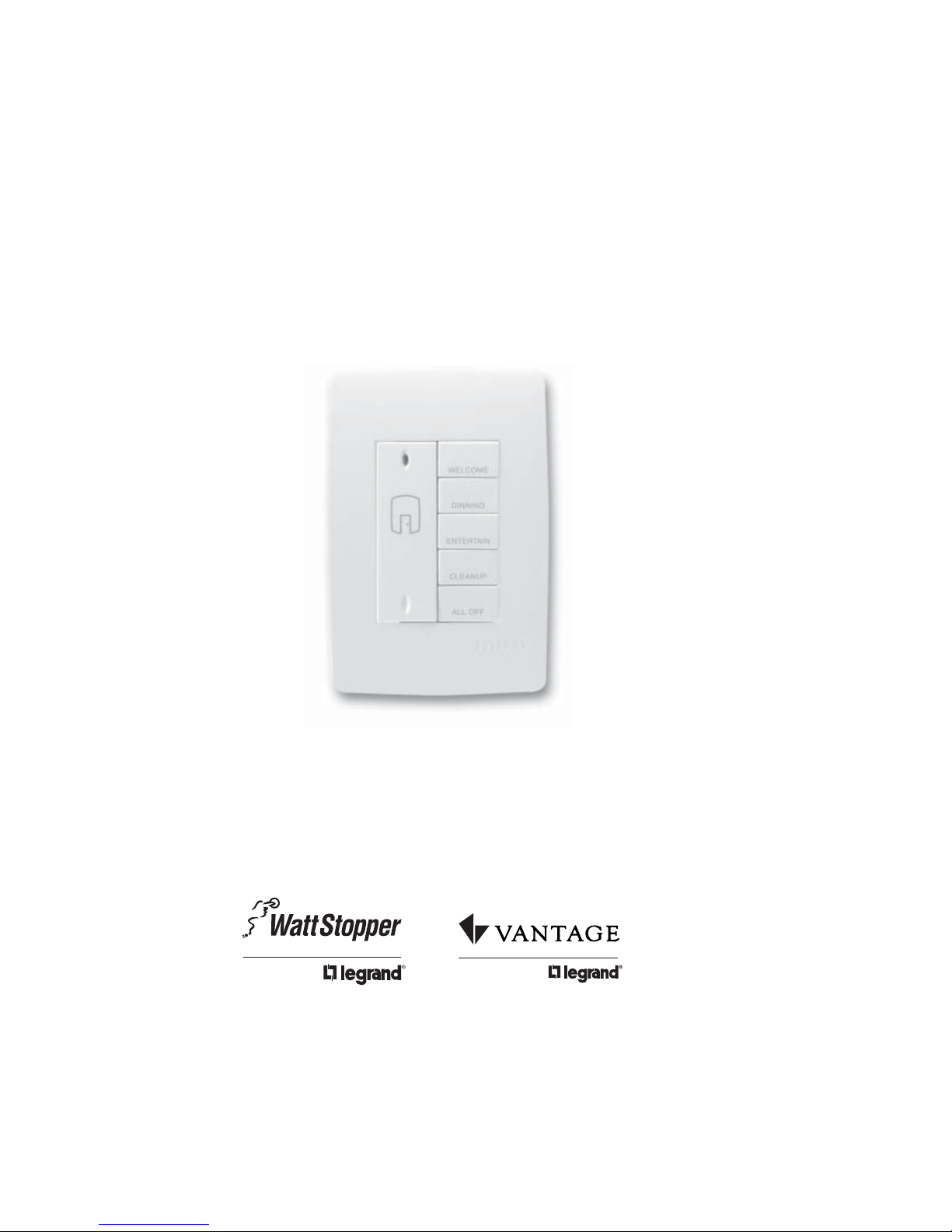
The Miro MRD6 Wireless Room Scene Controller is a room level scene controller.
It provides instant recall of fi ve user-recorded lighting scenes (or presets)
assigned to a room or designated area. It also provides off and on functions and
overall control of the room’s light level.
The MRD6 is mounted inside a wall box and framed by an
architectural screwless Miro wall plate (required and sold
separately). It can be identifi ed by the icon on its front, which
resembles the outline of a door leading to a room.
The Miro wireless room scene controller works as part of a Miro
wireless system. It can control a variety of Miro wireless devices including
dimmers, switches, plug-in appliance modules and plug-in lamp modules.
You can control up to fi fteen scenes in the room (see MORE SCENES section). You
can install additional room scene controllers or MRH6 room scene remotes to
control those scenes from multiple locations.
Note: To control the entire house, use a Miro wireless house scene controller (a
wall mounted MRD5 or a handheld MRH5 remote).
Miro Wireless
Miro wireless devices use radio signals to communicate with each other to
control lighting and other types of electric loads in selected areas. They use the
900MHz band for high-speed control communication. Using the Watt Stopper’s
own “frequency-agile” Top Dog™ technology, Miro wireless devices avoid
interference with other 900MHz devices, such as cordless phones and baby
monitors.
Application Assistance
The Miro Installation Guide provides more information about confi guring scenes.
Instructions for installation and use are included with the relevant Miro wireless
devices. Application support information and the Miro Installation Guide is
available online.
Page 3
INSTALLATION
1. Disconnect power to circuit by turning circuit breaker OFF.
CAUTION
TURN THE POWER OFF AT THE CIRCUIT BREAKER
BEFORE INSTALLING THE DEVICE.
Install only using a UL Listed Miro cover plate and subplate
assembly. If you do not have the proper Miro subplate for your
application, obtain one from any supplier of Miro devices.
2. Remove existing cover plate and switch.
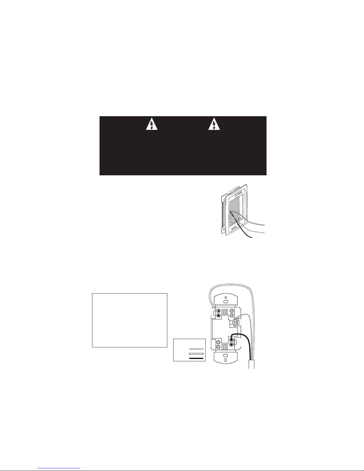
3. Temporarily attach the steel subplate for the Miro
cover plate to the wall box.
Wall box
Steel
subplate
4. Pull the wiring through the new Miro subplate.
5. Strip existing wires 1/2”. If two wires will be
connected to the same terminal on a Miro device, both
wires must be the same gauge (12AWG or 14AWG).
6. Wire the LINE (black), NEUTRAL (white) and GND (green or bare) supply
wires to the correspondingly marked screw terminals, according to the wiring
diagram below.
7. Using the instructions provided with the Miro cover plate, attach the MRD6 to
the metal subplate and to the wall box, then attach the Miro cover.
8. Switch the circuit breaker back ON.
INSTALL IN COMPLIANCE WITH
ALL APPLICABLE CODES &
NEUT
STANDARDS.
Failure to follow these
GND
instructions may cause personal
injury or equipment damage.
Wire Legend
Ground
Neutral
Line
LINE
Supply
Wires
Page 4

SET HOUSE ID
All Miro wireless devices installed in the same home must acquire the same
unique House ID before use. This process is known as house binding. Each Miro
wireless device is bound to all other Miro wireless devices in the house.
New Installation
1. With all devices installed and energized, make sure that every Miro wireless
device LED is yellow. If any LED is off, be sure the circuit breaker is on and the
device is correctly installed.
2. Press
on any device paddle until
the LED fl ashes yellow (about 2
seconds). This indicates that it has
acquired a unique House ID.
3. Make sure that all other Miro
wireless device LEDs are fl ashing
green, indicating that they have
acquired the same House ID.
4. Return to the device used in step 2, which is still fl ashing yellow. Press
until the LED changes to solid green (about 2 seconds). All device LEDs in the
House change to solid green, indicating house binding is complete.
Adding an MRD6 to an Existing Installation
If you’re adding or replacing a MRD6 in a Miro wireless installation that is
already operating, the new MRD6 must acquire the same House ID as the other
Miro wireless devices in the house. After the new MRD6 is powered up, the LED
should be solid yellow. This indicates that it has not yet acquired a House ID. To
acquire the House ID for the existing system:
1. Press
seconds).
2. Verify that the newly added MRD6 LED is fl ashing green, indicating that it has
acquired the House ID.
3. Return to the same previously bound device used in step 1 and press until
the LED changes to solid green (about 2 seconds). All device LEDs should now
be solid green.
on any previously bound device until the LED fl ashes yellow (about 2
When you see
in the instructions,
firmly press and
hold both the top
and bottom of
the paddle until
the LED changes
(about 2 seconds).
A
B
C
D
E
When you see in the
instructions, touch
the top of the paddle
as directed.
When you see in the
A
instructions, touch the
B
C
bottom of the paddle
D
E
as directed.
Page 5

ROOM BINDING
After the House ID is set in the MRD6, you create a room by binding devices to
the MRD6. You can also add the MRD6 to an existing room. When a new MRD6 is
added to a room, its scene buttons execute the same scenes as other room scene
controllers with the same scene set assignment (see MORE SCENES). Paddle
functions are the same at every room scene controller that is bound to the same
room, regardless of scene set assignment.
IMPORTANT: If you are planning to use Groups in the room, you should bind
those devices together before beginning the room binding process. Group
binding instructions are provided with individual devices.
Binding a New Room
1. With all devices installed and energized, make sure that every Miro wireless
device LED in the room is green.
2. Press on the MRD6 until its LED fl ashes yellow (about 2 seconds). You now
have 5 minutes to complete this process.
3. To include or exclude a device press on the device until the LED changes
color.
Yellow fl ashing LED = Included in room
Green fl ashing LED = NOT included in room
If a device is NOT fl ashing, see TROUBLESHOOTING.
4. Return to the MRD6 used in step 2. Press
LED stops fl ashing, then all the status LEDs in the house turn green.
Adding an MRD6 to an Existing Room
If you’re adding an MRD6 in a room where room level scene control is already
operating, the new MRD6 must fi rst acquire the House ID (see Adding an MRD6
to an Existing Installation). Then it must be bound to the existing room as follows:
1. Press
remote in the room until the LED fl ashes yellow (about 2 seconds).
2. Verify that the new MRD6 LED is fl ashing green. All other devices included in
the room are fl ashing yellow. Press
color.
Yellow fl ashing LED = Included in room
Green fl ashing LED = NOT included in room
3. Return to the same previously bound MRD6 used in step 1 and press
the LED changes to solid green (about 2 seconds). All device LEDs should be
solid green.
on any previously bound MRD6 room controller or MRH6 room
for about 2 seconds — the status
on the new MRD6 until its LED changes
until
Page 6

STANDARD OPERATION
e
The MRD6 is shipped with most functions preprogrammed for ease of installation
and initial use. This section summarizes the default operation of the MRD6.
To make changes from this standard operation, such as changing light levels
and including or excluding devices from specifi c scenes, see CUSTOMIZING
OPERATION.
Paddle Functions
Use the rocker paddle to begin and end binding functions. It also functions as
an On/Off switch and a master light level Raise/Lower control for the room.
All devices bound to the same room as the MRD6 are included in the paddle
operation (except fan controls).
Scene Button Functions
The smaller buttons, labeled A—E in the illustrations, are used to record and
recall scenes. Labels are provided so that you can name these buttons to suit
your application. All devices bound to the same room as the MRD6 are included in
each scene button (except fan controls).
The following illustration shows the default operation for scene set 1-5.
Paddle Scene Buttons3
Tap once: Raise all room
devices to 100% (ON)
Press and hold: Raise the
current scene’s level
Press and hold: Lower the
current scene’s level
1, 2
1
Tap once: Lower all room
devices to 0% (OFF)
Tap once: All room
Dimmers / Switches
to to
100% ON
A
75% ON
B
50% ON
C
D
25% ON
E
0% OFF
Press and hold:
Saves the current
device settings as
the scene that is
recalled the next tim
you tap this button.
See CUSTOMIZING
OPERATION.
NOTES:
1 Pressing and holding the paddle does not affect the operation of switched
devices. They will maintain their present state.
2 If the lights were turned off using the default E scene button or any
customized scene button programmed for 0%/ALL OFF, pressing and holding
will not raise the light level. It will raise the light level if the lights were
turned off by tapping
3 Scene buttons on MRD6 controllers with scene set 6-10 or 11-15 are
preprogrammed to turn off all room devices.
.
Page 7

CUSTOMIZING OPERATION
Modify and Save the Light Levels of a Scene
1. Change lighting levels as desired by pressing or on individual devices.
2. Press and hold the scene button until the LED fl ashes (about 2 seconds) to
save the new settings.
Removing or Adding Devices to a Scene
1. Press on the MRD6 until the LED begins fl ashing (about 2 seconds).
2. Press the scene button that you wish to program. LEDs on all wireless Miro
devices begin to fl ash. You now have 5 minutes to complete this process.
3. To include or exclude a device in the scene press
changes color. Yellow fl ashing LED = Included in the active scene
Green fl ashing LED = NOT included in the active scene
If a device is NOT fl ashing, see TROUBLESHOOTING.
NOTE: You must include devices that are off in the room scene if you want
them to turn off when that scene is recalled.
4. Return to the MRD6 used in step 1. Press
stops fl ashing, then all the status LEDs in the house turn green.
Removing or Adding Devices to the Paddle “On” Function
1. Press on the MRD6 until the LED begins fl ashing (about 2 seconds).
2. Tap the
begin to fl ash. You now have 5 minutes to complete this process.
3. To include or exclude a device press
color. Yellow fl ashing LED = Included in paddle operation
Green fl ashing LED = NOT included in paddle operation
If a device is NOT fl ashing, see TROUBLESHOOTING.
4. Return to the MRD6 used in step 1. Press
LED stops fl ashing, then all the status LEDs in the house turn green.
5. To test, tap
switch included devices to on (dimmers go to full bright).
paddle on the MRD6. The LEDs on all the Miro wireless devices
on the device until the LED changes
on any room scene controller that is bound to the same room to
on the device until the LED
for 2 seconds — the status LED
for about 2 seconds — the status
Removing or Adding Devices to the Paddle “Off” Function
1. Press on the MRD6 until the LED begins fl ashing (about 2 seconds).
2. Tap the
begin to fl ash. You now have 5 minutes to complete this process.
3. See step 3 above.
4. See step 4 above.
5. To test, tap
switch or fade included devices to off (dimmers go to 0%)
paddle on the MRD6. The LEDs on all the Miro wireless devices
on any room scene controller that is bound to the same room to
Page 8

MORE SCENES
Up to 15 scenes are available per room. Each room level controller can access
a set of 5 scenes. The MRD6 is assigned to scenes 1-5 when shipped. Changing
to scene set 6-10 lets you record 5 more scenes; changing to scene set 11-15
lets you record another 5 scenes. Binding three room level controllers (MRH6 or
MRD6) to the room and assigning each to a different scene set, lets you dedicate
a controller to each scene set. You can bind more room scene controllers to the
room to control the same scenes from multiple locations.
All room scene controllers that have the same scene set assignment operate
the 5 scenes in the same way as all other room scene controllers programmed
for the same set. Scene buttons on controllers with scene sets 6-10 and 11-15
default to 0%/All room devices OFF. Use ROOM BINDING and CUSTOMIZING
OPERATION procedures to set up the additional scene controllers.
To assign scenes 6-10, simultaneously press
and B until the LED blinks twice (about 2 seconds).
To assign scenes 11-15, simultaneously press
and C until the LED blinks twice (about 2 seconds).
To change the assignment back to scenes 1-5,
simultaneously press
and button A until the LED
A
B
C
D
E
blinks twice (about 2 seconds).
A = 1-5 (default) B = 6-10 C = 11-15
Assigning the MRD6
for scene set 6-10
LOCK ROOM CONFIGURATION
The Lock Confi guration function operates from a wireless Miro room level
controller, and prevents the Miro wireless devices in the room from being
reprogrammed. Other operations such as dimming, switching and scene recall
are not affected.
When the confi guration is locked, if
device, the device’s LED fl ashes red and the command is ignored.
To lock the confi guration:
Go to any room scene controller. Simultaneously press
and buttons B and E until the LED fl ashes (about 2
seconds) to toggle in and out of Lock Confi guration.
• If the mode changes from unlocked to locked,
the LED fl ashes red for 2 seconds, indicating that
confi guration is now locked.
• If the mode changes from locked to unlocked, the
LED fl ashes green for 2 seconds, indicating that
confi guration is now unlocked.
is pressed and held on any Miro wireless
A
B
C
D
E
Page 9

TROUBLESHOOTING
During house ID binding, the LED is not fl ashing on some devices.
• If LED is solid green before initiating house ID binding:
The device already has another house ID. Reset it to the factory default so
that it can be bound to the desired house ID. Resetting to factory defaults is
described in “I made a confi guration mistake. I need to start over.”
• If LED is solid yellow after initiating house ID binding:
The device may be out of range of the initiating device. Add a MRR2
Wireless Repeater to boost signal range.
During binding or customizing, all LEDs stop fl ashing before I press
The 5 minute binding process timer may have expired. Restart the timer by
repeating steps 1 and 2 of the procedure you were using. Notice that the devices
you previously excluded are fl ashing green; those included are fl ashing yellow;
simply fi nish the process from where you left off.
The device LED fl ashes red when I press
The house or room confi guration may be locked.
Go to any house level scene controller and simultaneously press and buttons
B and E until the scene controller LED fl ashes GREEN.
Go back to the previously locked device and press
• If it fl ashes green or yellow, you have unlocked the house confi guration.
• If the device still fl ashes red, the confi guration may be locked
by a room level scene controller such as the MRD6 or MRH6.
Go to the room scene controller and simultaneously press
B and E until the scene controller LED fl ashes GREEN. (See LOCK ROOM
CONFIGURATION.)
Go back to the previously locked device and press
• If it fl ashes green or yellow, you have unlocked the room confi guration.
• If the device still fl ashes red, the confi guration may be locked
by another room level scene controller in the house. Repeat the procedure
from different controllers until the device is no longer fl ashing red.
.
.
.
.
and buttons
I made a configuration mistake. I need to start over.
To reset any Miro wireless device to factory default settings, press and hold
-
- until the LED changes to solid yellow (approximately 10 seconds).
During the process, the LED fl ashes yellow. When complete, it becomes solid
yellow. The device can then be reconfi gured, exactly like any new device.
CLEANING
Clean only using a cloth dampened with water and a little mild detergent. Use of
solvents or hydrocarbon-based cleaners may cause permanent damage.
Page 10

POWER FAIL MEMORY
After a power failure, all Miro devices automatically return to the state that they
were in immediately prior to loss of power. All house binding and scene control
information is preserved.
FCC NOTICE
This equipment has been tested and found to comply with the limits for a Class
B digital device, pursuant to part 15 of the FCC Rules. These limits are designed
to provide reasonable protection against harmful interference in a residential
installation. This equipment generates, uses and can radiate radio frequency
energy and, if not installed and used in accordance with the instructions, may
cause harmful interference to radio communications. However, there is no
guarantee that interference will not occur in a particular installation. If this
equipment does cause harmful interference to radio or television reception,
which can be determined by turning the equipment off and on, the user is
encouraged to try to correct the interference by one or more of the following
measures:
• Reorient or relocate the receiving antenna.
• Increase the separation between the equipment and receiver.
• Connect the equipment into an outlet on a circuit different from that to which
the receiver is connected.
• Consult the dealer or an experienced radio/TV technician for help.
Caution: Any changes or modifi cations to this device not explicitly approved by
manufacturer could void your authority to operate this equipment.
WARRANTY INFORMATION
Manufacturer warranties its products to be free of defects in materials and
workmanship for a period of fi ve (5) years. There are no obligations or liabilities
on the part of manufacturer for consequential damages arising out of, or
in connection with, the use or performance of this product or other indirect
damages with respect to loss of property, revenue or profi t, or cost of removal,
installation or reinstallation.
Watt Stopper Customers contact: Vantage Customers contact:
2800 De La Cruz Blvd.
Santa Clara, CA 95050
Phone: 800.879.8585
www.wattstopper.com
Please
Recycle
08532r2 9/2007
1061 South 800 East
Orem, UT 84057
Phone: 800.555.9891
www.vantagecontrols.com
 Loading...