

Page 1
REV DESCRIPTION INT: REV. DATE APPROVED
Center Fold
1 ECO# C01556 MJS 10/9/06 CG
2 ECO# C01973 MJS 10/11/2006 CG
3 ECO# C02415 DR
TITLE BOX PAGE ONLY.
DO NOT MAKE FILM • DO NOT PRINT
MATERIAL: White 16lb (60g/m sq), uncoated, prefer recycled stock
Ink: Black
Print Two Sides, 2 sheets 8.5” (Wide) x 11” (High),
stapled upper left corner
OR
Print Two Sides, 1 sheet 11” x 17”
folded to 8.5” x 11”
11”
431.8mm
279.4mm
11”
17”
Front PageBack Page
Inside Right PageInside Left Page
215.9mm
8.5”
MRx###
MRx###
MRx###
Front of Sheet
Back of Sheet
4-page
booklet
fold
IF YOU HAVE ANY QUESTIONS REGARDING SPECIFICATIONS OR REQUIRE
ADDITIONAL FILE FORMATTING, PLEASE CONTACT Mary Jo Sowinski.
Phone: 408-486-7511
Email: maryjo.sowinski@wattstopper.com
All information in this drawing is the property of Watt Stopper/Legrand
and cannot be copied or used without the written approval of
DRAWN BY
PLM
MARCOM
ENGINEERING
QA
TITLE BOX PG
REVEL
SCALE 1:1
Watt Stopper/Legrand.
SANTA CLARA, CALIFORNIA
Title: MR2000 Installation Instructions
Drawing #:
06145
Orig. Drawing Date: 06 OCT 06
Revision Date: 01 OCT 07
REV. #:
3
Page 2
SPECIFICATIONS
Miro 2000 W Dimmer
Voltages ............................................... 120VAC/277VAC, 60Hz
Output (Load) .................Powered via Input (Line) to Neutral
Maximum Load Rating .......2000W@120VAC, 4432W@277VAC
Minimum Load Required ...... 100W@120VAC, 200W@277VAC
Load Type Compatibility ..........................................................
Note: Burn-in lamps according to manufacturer’s
instructions before dimming with the MR2000.
The following are limited to 2000W@120VAC max:
Incandescent & quartz halogen
Electronic low voltage dimming rated transformers
Neon/cold cathode dimming rated ballasts
The following are limited to 2000W@120VAC or
4432W@277VAC max:
Magnetic low voltage transformer
Dimming rated 2-wire fluorescent (Advance
MarkX or equivalent)
Compact fluorescent dimming rated ballasts
Required Branch Circuit Overcurrent Protection
Ratings: ................................. 120VAC/277VAC, 20A, 60 Hz
Environment
Operating Temperature ...................... 32°-104°F (0°-40°C)
Operating Humidity .... Less than 95%RH, non-condensing
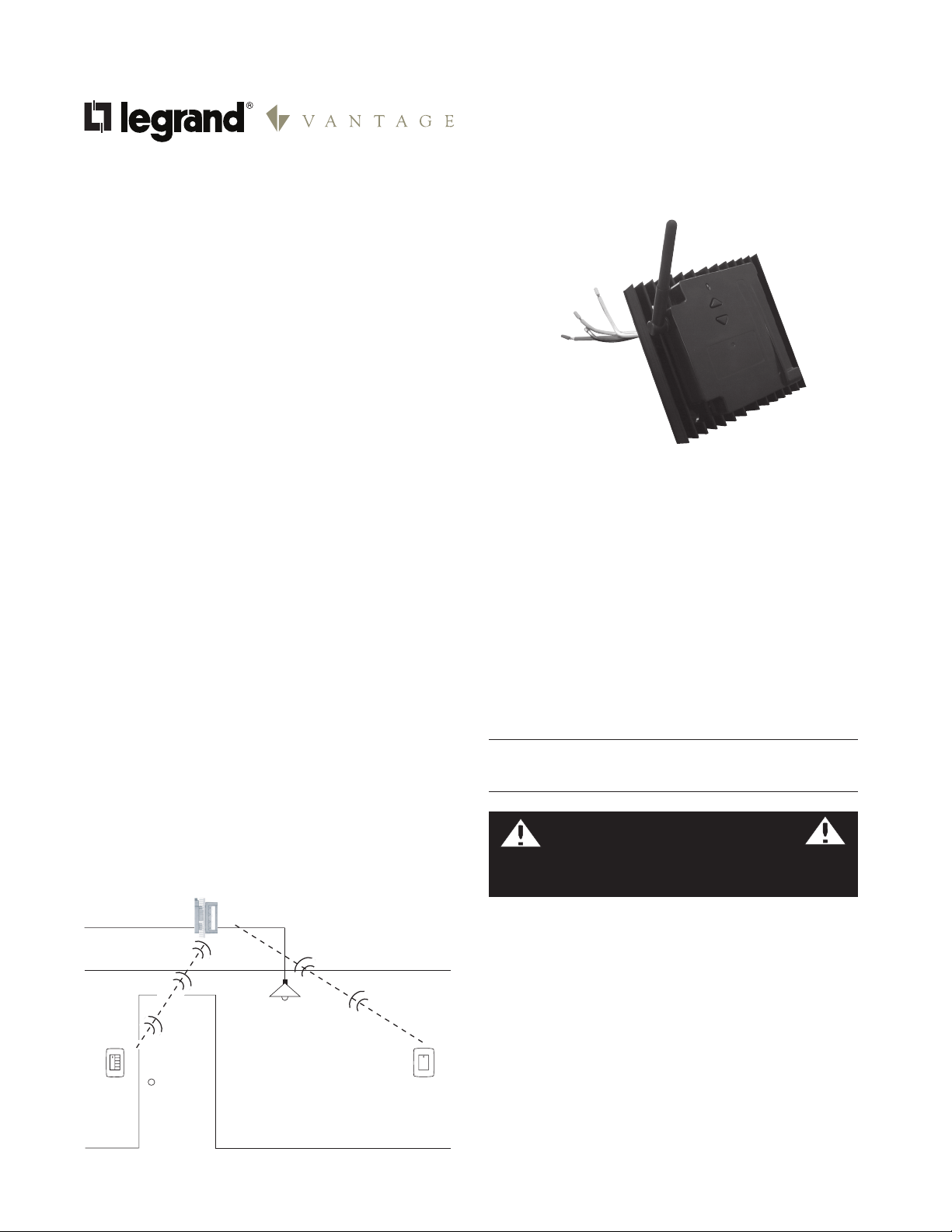
DESCRIPTION
The Miro MR2000 is a high capacity universal dimmer
designed for remote mounting in a 4” square box with a 1½”
extender. The dimmer is suitable for surface, semi-recess
or plenum mounting. Remote user control is available by
either binding the MR2000 to a wireless Miro control device
such as a wireless multilocation controller (see Figure 1)
or by wiring the MR2000 to a Miro multilocation controller
through a traveler wire (see Figure 2).
The MR2000 is wired directly to the load. It is a forward
phase control dimmer with a normally open air-gap relay
at the load output. It provides 120/277VAC, phase to neutral
input to the load.
I n stallation Inst r u c t i o n s
MR2000
Universal Dimmer
Top Dog™ Wireless Communication
Wireless devices use radio signals to communicate with
each other to control lighting and other types of electric
loads in selected areas. These wireless devices use the
900MHz band for high-speed control communication. Using
“frequency-agile” Top Dog™ technology, these wireless
devices avoid interference with other 900MHz devices, such
as cordless phones and baby monitors.
Load Types
Use the Miro Universal Dimmer for these load types:
• Incandescent&quartzhalogenlamps.
• Dimmable,2-wirefluorescentandcompact
fluorescent, electronic low voltage, magnetic low
voltage, neon or cold cathode.
Do not mix different load types on the same dimmer.
Do not use with fluorescent lamps other than
those listed. See SPECIFICATIONS.
CAUTION
Do not install to control a receptacle,
or a motor-operated appliance.
Power
Scene
Controller
Multilocation
Controller
ENVIRONMENT AND ORIENTATION
This product is designed for indoor use only where the
ambient temperature in the unit’s vicinity does not exceed
104°F (40°C). Allow space for ventilating 100 BTU/Hr.
Unit must be mounted in a 2¹⁄8” deep 4” square steel
electrical box plus 1½” extension such that the heatsink is
spaced 1½” away from the wall in which the 4” square box
is mounted. Unit must be oriented such that the heatsink
fins run lengthwise vertically to permit natural upward
convection whether wall or plenum mounted. Allow a
minimum of 6” space above and below the unit and do not
block vertical airflow though the heatsink.
Page 3

WIRING INSTRUCTIONS
1. Disconnect power to the circuit by turning the circuit
breaker OFF before installation.
WARNING
TURN THE POWER OFF AT THE CIRCUIT
BREAKER BEFORE INSTALLING THE DIMMER.
2. Strip existing wire ½” (12.7mm).
3. Wire the LINE (black), NEUTRAL (white) and LOAD lead
wires to the supply/load wires per Figure 2. If installing
in a grounded metal box, the unit will be grounded to
the electrical box. Otherwise, use the green ground
screw to connect to ground as shown in Figure 2. Use
#12AWG copper wire. Depending on the application and
the number of connections, more space may be needed.
If so, use an appropriate size box or box extension.
4. If the MR2000 will be controlled by a wired multilocation
controller (MCD68/DCD68) connect the yellow traveler
wire per the instructions provided with the controller.
If using the MR2000 in a Miro wireless network, the
yellow traveler wire is not used and must be capped.
5. Switch the circuit breaker back ON.
6. If the unit is to be controlled from a Miro wireless
device, refer to “SET HOUSE ID” on the next page.
INSTALLATION
The unit must be installed in compliance with the
Environment and Orientation instructions.
Disconnect power when servicing fixture
or changing lamps. Both lighting fixture
and dimmer must be grounded. Use
this device only with copper wire.
Radio communication cannot be guaranteed if the unit is
mounted in a metallic electrical enclosure.
1. Install dimmer in a 2¹⁄8” minimum deep 4” square (1900)
electrical box with a 1½” extension. Extension must
extend beyond wall such that the heatsink is spaced a
minimum of 1½” from the wall.
2. For both wall and plenum mounting, orient the dimmer
so that the heat sink fins run vertically, allowing natural
upward convection.
3. Allow a minimum of 6” space above and below the unit
and do not block vertical airflow through the heat sink.
Requires 100 BTU/hour ventilation.
CAUTION
INSTALL IN COMPLIANCE WITH ALL APPLICABLE CODES
& STANDARDS. Failure to follow these instructions may
cause personal injury or equipment damage.
Max. traveler wire 200' (60m)
GND
(Connect
to
building
ground)
GND
Load
Wires
Supply
Wires
Multilocation
Controller
Wire Legend
Traveler (YEL)
Ground
Neutral (WHT)
Line (BLK)
Load (RED)
Figure 2 - Wiring Diagram
A Miro 2000W Dimmer is compatible with wired Miro
devices, as shown above connected by a traveler wire
between the MR2000 and the Multilocation Controller (either
MCD68 or DCD68). It will also communicate with a wireless
Miro network (see Figure 1).
Figure 3 - Mounting Diagram
OPERATION
• Whenyousee in the instructions, press the top
button on the MR2000, or the top of the paddle when
referencing other Miro devices.
• Whenyousee in the instructions, press the bottom
button on the MR2000, or the bottom of the paddle when
referencing other Miro devices.
• Whenyousee in the instructions, simultaneously
press and hold BOTH the UP and the DOWN buttons on
the MR2000 (or, when referencing other Miro devices,
firmly press and hold BOTH the top and bottom of the
device paddle).
1 tap = last used level
2 taps = full output
Press and hold = raise light
level
1 tap = fade to OFF
Press and hold = reduces
light level
Figure 4: User Interface, dimming controls
Page 4

FLUORESCENT SETUP
If the dimmer will operate 2-wire fluorescent or compact
fluorescent loads, a special configuration step is required.
1. Press and hold until the LED flashes yellow (about 2
seconds).
2. Press the top of the device paddle until the LED
briefly flashes red.
3. Press and hold until the LED changes to green (about
2 seconds.
4. To reconfigure the dimmer to control non-fluorescent
loads, repeat the above steps 1-3, but press the bottom
of the device paddle rather than in step 2; the LED
briefly flashes green to confirm the cancellation of
fluorescent operation.
SET HOUSE ID
(for wireless applications only)
All Miro wireless devices installed in the same system must
acquire the same unique House ID before use. This process
is known as house binding. Each Miro wireless device is
bound to all other Miro wireless devices in the house.
New Installation
1. With all devices installed and energized, make sure that
every Miro wireless device LED is yellow. If any LED is
OFF, be sure the circuit breaker in ON and the device is
correctly installed.
2. Press on any device paddle until the LED flashes
yellow (about 2 seconds). This indicates that it has
acquired a unique House ID.
3. Make sure that all other Miro wireless device LEDs are
flashing green, indicating that they have acquired the
same House ID.
4. Return to the device used in step 2, which is still
flashing yellow. Press until the LED changes to solid
green (about 2 seconds). All device LEDs in the House
change to solid green, indicating house binding is
complete.
Adding a Device to an Existing Installation
If you are adding or replacing a device in a Miro wireless
installation that is already operating, the new device must
acquire the same House ID as the other Miro wireless
devices in the house. After the new device is powered up,
the LED should be solid yellow. This indicates that it has
not yet acquired a House ID. To acquire the House ID for the
existing system:
1. Press on any previously bound device until the LED
flashes yellow (about 2 seconds).
2. Verify that the newly added device LED is flashing
green, indicating that it has acquired the House ID.
3. Return to the same previously bound device used in
step 1 and press until the LED changes to solid green
(about 2 seconds). All device LEDs should now be solid
green.
ADVANCED OPERATION FOR WIRELESS
Application Assistance for wireless
The MR2000 can function as part of a network that may
contain a variety of wireless devices. The MR2000 may
be easily incorporated into room and whole house preset
scenes. Instructions for installation and use are included
with the relevant Miro wireless room and whole house
control devices.
The Miro Installation Guide provides more information
about configuring scenes and presets. Application support
information and the Miro Installation Guide is available at:
www.wattstopper.com.
Groups
Use a MR2000 dimmer in conjunction with one or more Miro
MRD8 Wireless Multilocation Controllers to control one
lighting circuit from multiple locations. Binding the MR2000
and MRD8/DRD8 devices together in the same Group
enables them to work in exactly the same way, from any of
the control locations.
You can include other Miro wireless devices in the Group.
Just remember that all devices in the Group operate when
one member operates. If you increase the brightness on one
circuit in the Group, all circuits will increase brightness.
A device can only belong to one group at any time.
Set the House ID (see Set House ID) before setting up
Groups.
1. Go to any device that you want to include in the Group.
Press . The device LED flashes yellow, and all other
devices in the House flash green*. You now have 5
minutes to complete this process.
2. To include or exclude a device in the Group press
the device until the LED changes color.
•Yellow flashing LED = Included in the Group
•Green flashing LED = NOT included in the Group
If you get to a device and it is NOT flashing, the 5-
minute binding process timer may have expired. Go
back to step 1 and repeat.
3. Return to the device used in step 1 and press
terminate Group binding. All LEDs revert to solid green.
Now, all the devices in the Group control their load
circuit in exactly the same manner.
*Adding a Dimmer to a Group in an Existing System
1. Go to a device that is in the Group where you want
to add the dimmer. Press . The device LED and all
members of the Group flash yellow. The new dimmer
flashes green.
2. Press on the new dimmer until it’s LED flashes
yellow.
3. Return to the device used in step 1 and press . All
LEDs are solid green.
on
to
Page 5

CLEANING & MAINTENANCE OPERATIONS
Clean only using a cloth dampened with water and a little
mild detergent. Use of solvents or hydrocarbon-based
cleaners may cause permanent damage.
Replacing Lamps
When a lamp must be replaced, disconnect power.
Power Fail Memory
After a power failure, all wireless devices automatically
return to the state that they were in immediately prior
to loss of power. All configuration and scene control
information is preserved.
TROUBLESHOOTING FOR WIRELESS
During Set House ID, the LED is not flashing on some
wireless Miro devices.
• IfLEDissolidgreenbeforeinitiatinghouseIDbinding:
The device already has another house ID. Reset it to the
factory default so that it can be bound to the desired
house ID. Resetting to factory defaults is described in
the “I need to start over” issue.
• IfLEDissolidyellowafterinitiatinghouseIDbinding:
The device may be out of range of the initiating device.
Add a MRR2 Miro Wireless Repeater to boost signal
range.
FCC NOTICE
FCC ID: Q4BMR2K
This device complies with part 15 of the FCC Rules.
Operation is subject to the following two conditions: (1) This
device may not cause harmful interference, and (2) this
device must accept any interference received, including
interference that may cause undesired operation.
Caution: Any changes or modifications to this device
not explicitly approved by manufacturer could void your
authority to operate this equipment.
I made a configuration mistake. I need to start over.
You can reset any Miro wireless device to factory default
setting by pressing and holding until the LED changes
to solid yellow (approximately 10 seconds). During the
process, the LED flashes yellow and when complete,
it changes to solid yellow. The device can then be
reconfigured, exactly like any new device (see the Set
House ID section).
The Dimmer does not work and the status LED is
flashing red.
• at1Hz(5timesin5seconds):
The dimmer has detected an unsuitable load or load
below the minimum rated load for the applied voltage.
To clear the fault condition, tap and wait for the
LED to turn green. Disconnect power, check the load,
restore power and try again.
WARRANTY INFORMATION
Manufacturer warranties its products to be free of
defects in materials and workmanship for a period
of five (5) years. There are no obligations or liabilities
on the part of manufacturer for consequential
damages arising out of, or in connection with, the
use or performance of this product or other indirect
damages with respect to loss of property, revenue or
profit, or cost of removal, installation or reinstallation.
Legrand Customers contact: Vantage Customers contact:
301 Fulling Mill Road Suite G
Middletown, PA 17057
Phone: 800.321.2343
www.legrand.us/onq
1061 South 800 East
Orem, UT 84097
Phone: 800.555.9891
www.vantagecontrols.com
Please
Recycle
06145r3 9/2007
 Loading...