

Page 1
MOSAIC
NURSE CALL UNIT
INSTALLATION AND USER GUIDE
THE GLOBAL SPECIALIST IN ELECTRICAL AND DIGITAL
BUILDING INFRASTRUCTURES
Page 2

Contents
DESCRIPTION OF THE SYSTEM ARCHITECTURE >> 3
Fundamental rules to follow when installing the Mosaic
nurse call system
Wiring diagram >>>>>>>>>>>>>>>>>>>>>>>3
Selection guide: how to draw up your list of equipment >>>4
DEVICE PRESENTATION AND INSTALLATION >>>>>5
0 766 60: 6-direction call display unit>>>>>>>>>>>>>5
0 782 14: table control unit >>>>>>>>>>>>>>>>>>7
0 782 12: 3-direction management module >>>>>>>>>7
0 782 89: 24 V 2 A 48 W POWER SUPPLY >>>>>>>>>>8
0 035 67: auxiliary power supply >>>>>>>>>>>>>>>8
0 782 04: door unit >>>>>>>>>>>>>>>>>>>>>>9
0 766 85: bathroom call units or call button >>>>>>>> 10
0 766 63: socket for push-button cord >>>>>>>>>>> 11
0 783 62: push-button cord >>>>>>>>>>>>>>>> 11
077150+078207:biomedicalcallplugandsocket>>>> 12
0 782 43: clamp for push-button cord >>>>>>>>>>> 13
0 766 64: bathroom call pull-cord >>>>>>>>>>>>> 13
0 766 72: double display corridor overdoor light >>>>>> 14
0 766 71: call transfer light for corridors >>>>>>>>>> 15
0 766 42: electronic buzzer>>>>>>>>>>>>>>>>> 15
MOSAIC NURSE CALL UNIT
Call + nurse present >>>>>>>>>>>>>>>>>>>> 16
Bathroom call + nurse present >>>>>>>>>>>>>>> 17
Emergency call >>>>>>>>>>>>>>>>>>>>>> 18
Nurse present + call from another room >>>>>>>>>> 19
Nurse present + call from another bathroom >>>>>>> 20
Call priorities >>>>>>>>>>>>>>>>>>>>>>> 21
Wiring: call + presence installation for nursing homes
and residential homes for the elderly
Wiring: call + presence installation with call via call button
and information transfer
Wiring: call + biomedical + presence installation with
DECT interface (integrated traceability)
COMMISSIONING
Check before switch-on >>>>>>>>>>>>>>>>>> 28
Resetting the module >>>>>>>>>>>>>>>>>>> 29
TROUBLESHOOTING >>>>>>>>>>>>>>>>>> 30
>>>>>>>>>>>>>>>>>>>>>>3
>>>>>>>>>>>>>> 16
>>>>>>>>>>> 22
>>>>>>>>>>>>>>>>>> 24
>>>>>>>>>> 26
>>>>>>>>>>>>>>>>>>>> 28
2
Page 3
DESCRIPTION
OF THE SYSTEM
ARCHITECTURE
DESCRIPTION OF THE SYSTEM ARCHITECTURE
Fundamental rules to follow when installing the Mosaic nurse call system
Patient call system products are associated with personal safety. They should therefore be installed by a qualified electrician, in strict
accordance with the conditions of installation and the operating instructions.
A single protection device should be installed for the entire nurse call system.
To ensure continuous operation during a mains failure, connect to an uninterruptible supply (generator and/or inverter). If there is a
mains failure longer than 1 s, all calls prior to the outage may be lost.
Note: The Mosaic nurse call system is recommended for installations with 1 to 72 directions*.
* Direction: room from which the calls originate
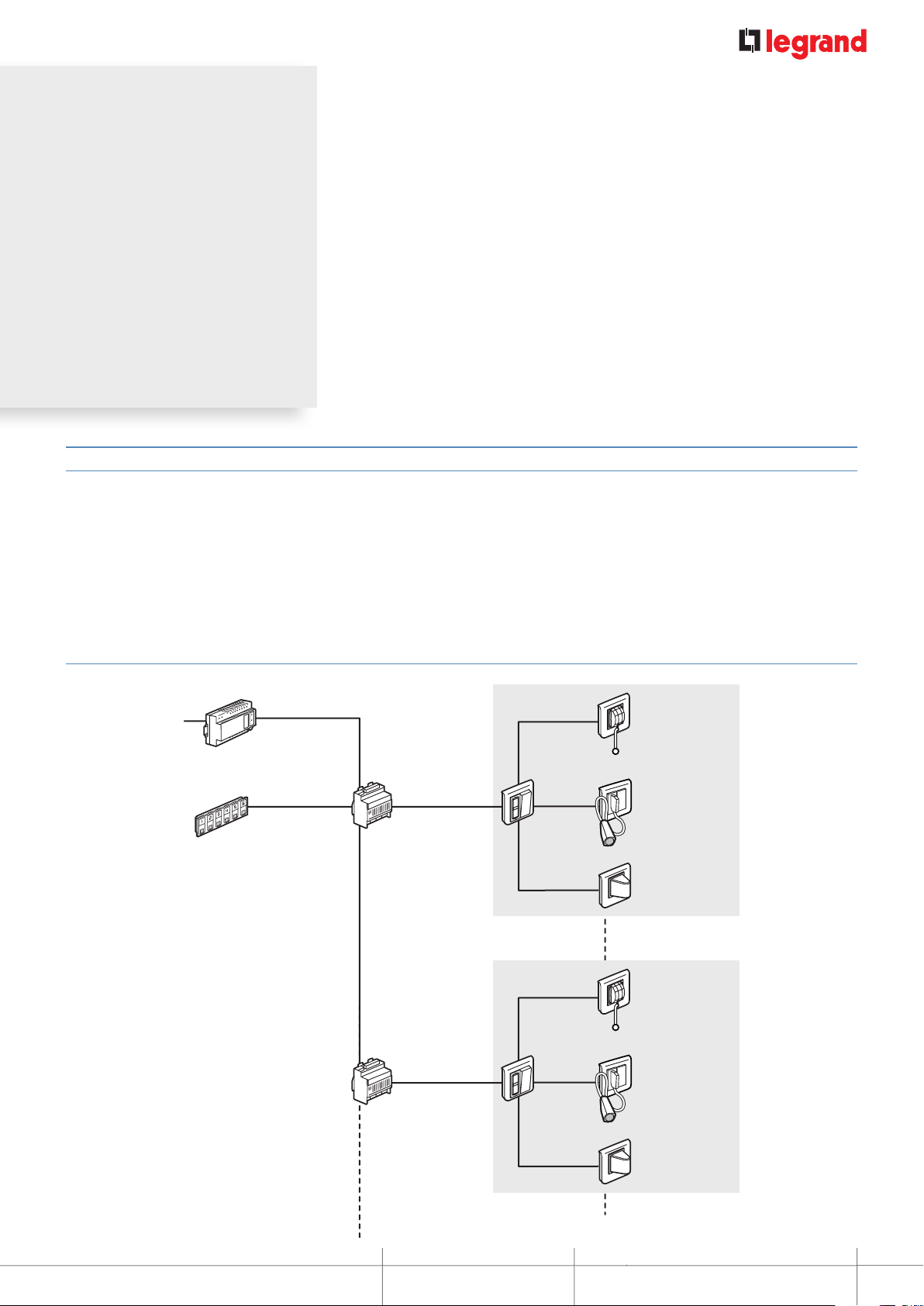
Wiring diagram
230 V±
6-direction display unit
Cat. No. 0 766 60
2x1.5mm
Power supply
Cat. No. 0 782 89
2
6 x 0.6 mm pairs
for 3 directions
2 x 0.6 mm pairs
per direction
Management module
Cat. No. 0 782 12
2 x 0.6 mm pairs
per direction
Management module
Cat. No. 0 782 12
Room 1
Room 4
2 x 0.6 mm pairs
1x0.6mmpair
Door unit
Cat. No. 0 782 04
2 x 0.6 mm pairs
2 x 0.6 mm pairs
1x0.6mmpair
Door unit
Cat. No. 0 782 04
2 x 0.6 mm pairs
Bathroom call unit
Cat. No. 0 766 64
Socket for
push-button cord
Cat. No. 0 766 63
Corridor overdoor
light unit
Cat. No. 0 766 72
Bathroom call unit
Cat. No. 0 766 64
Socket for
push-button cord
Cat. No. 0 766 63
Corridor overdoor
light unit
Cat. No. 0 766 72
MOSAIC NURSE CALL UNIT
Room 7
INSTALLATION AND USER GUIDE
3
Page 4
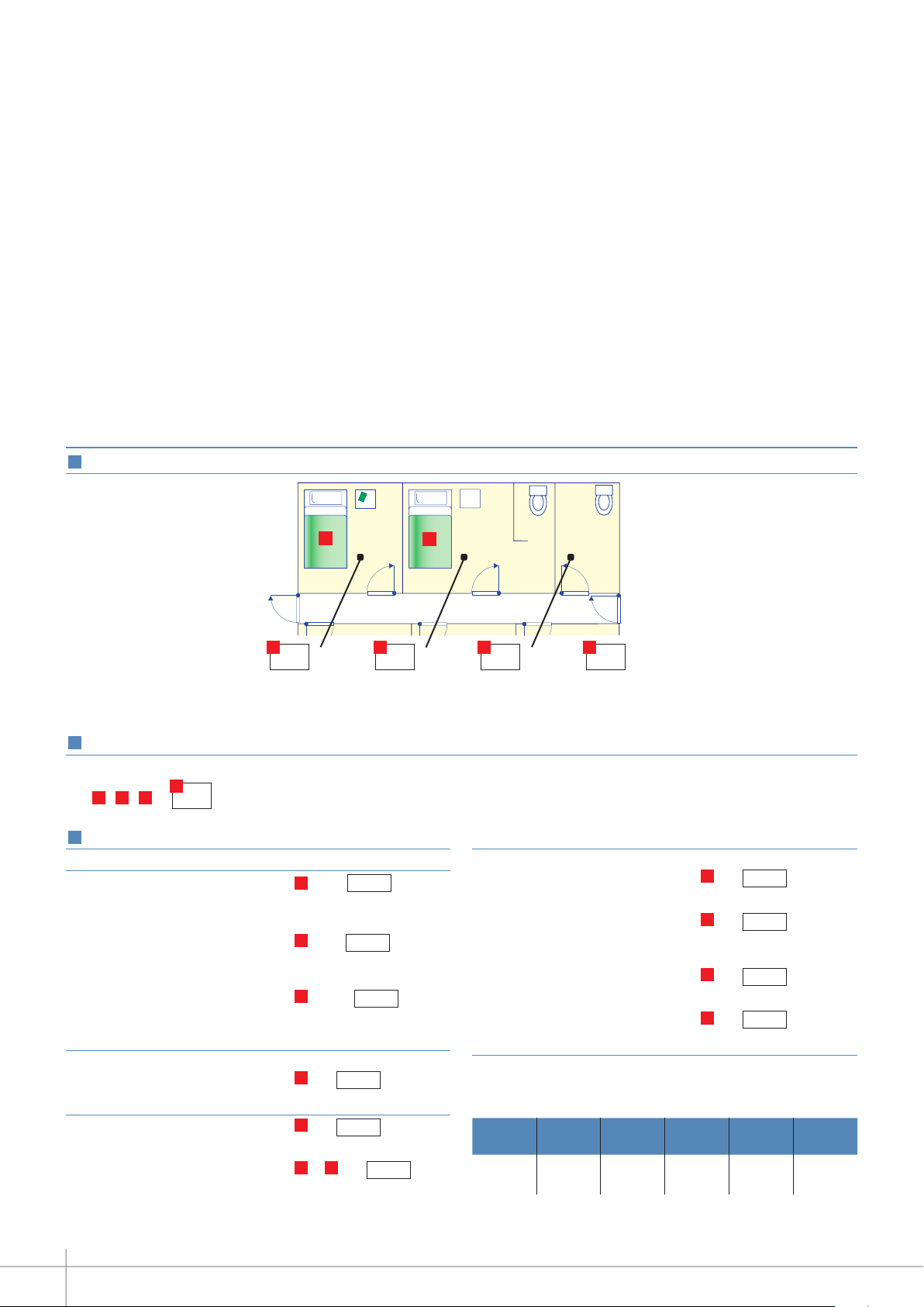
DESCRIPTION OF THE SYSTEM ARCHITECTURE
SELECTION GUIDE: HOW TO DRAW UP YOUR LIST OF EQUIPMENT
1
Gather the following information
D
D
A B C D
Number of
separate rooms
2
Calculate the number of directions
To determine the number of directions, simply add:
BCA
++=
3
Draw up your list of equipment
E
Nurses' station and management equipment
Display unit Cat.No 0 766 60 =
E
/6 i.e.
displays
Management module
Cat.No 0 782 12 =
E
/3 i.e. modules
Option:
Table control unit
Cat.No 0 782 14 =
E
/36 i.e. control
units
Corridor equipment
Corridor overdoor light units
Cat.No 0 766 72
E
=
i.e. light units
Room/bathroom equipment
Door unit Cat.No 0 782 04 =
E
i.e. door units
Bathroom call unit
Cat.No 0 766 64 =
B +C
i.e.
call units
D
D
Number of
rooms with WC
Number
ofseparate WCs
Number
of beds
Bed equipment
Socket for push-button cord
Cat.No 0 766 63 =
D
i.e. sockets
Push-button cord
Cat.No 0 783 62 =
D
i.e. cords
Option:
Shunt plug for biomedical
alarm Cat.No 0 782 07 =
D
i.e. plugs
Socket for biomedical alarm
Cat.No 0 771 50 =
D
i.e. sockets
Power supply:
Power supply Cat.No 0 782 89
Number of power supplies to be calculated using the table
below
0 782 04 0 766 72 0 766 64
0 782 88
0.7 W 0.9 W 0.7 W 0.8 W 1 W 0.4 W per
078281/
82/84
0 782 12 0 766 60
direction
Recommendation: 1 power supply for 36 directions (corresponds to 30%
of simultaneous calls max.)
4
Page 5

DEVICE PRESENTATION
AND INSTALLATION
0 766 60: 6DIRECTION CALL DISPLAY UNIT*
Direction
identification*
Mute button
Identification labels
supplied
Main display unit: used to monitor rooms in the department from
the nurses' station.
Secondary display unit: used to transfer information from the
main display unit. 4 secondary display units max.
Indicates calls by lighting up numbered indicator lights and
generating an audible signal.
Can indicate several calls simultaneously.
Displays the call and nurse presence and mute setting.
Calls can be transferred to 4 other display units (treatment room,
rest area, etc.).
Supplied without plate.
Supplied with sheets of numbered stickers from 1 to 99.
Technical characteristics
n Power supply: 24 V=
n Consumption: min. 0.4 W - max. 2.8 W
n Operating temperature: 5 to 40°C
n Protection class: IP 40
n Dimensions: 135 x 22.5 mm
n Installation:
- On table control unit Cat.No 0 782 14
- Flush-mounted in 50 mm deep box Cat.No 0 800 53
- Surface-mounted with 40 mm deep box Cat.No 0 802 86
n Sound level: - 65 dB (A) at 1 m placed on table
- 75 dB (A) fixed to wall 1.60 m off the floor
- 62 dB (A) at 1 m placed on table
- 72 dB (A) fixed to wall 1.60 m off the floor
ConnectionPerforms the main and secondary display functions.
1 2
3
4 5 6 7
1- Management module terminals
2- Room 6 terminals
3- Room 1 terminals
4- Room 2 terminals
5- Room 3 terminals
6- Room 4 terminals
7- Room 5 terminals
0 766 60
* Direction: room from which the calls originate
DESCRIPTION OF THE SYSTEM ARCHITECTURE
INSTALLATION AND USER GUIDE
5
Page 6

DEVICE PRESENTATION AND INSTALLATION
0 766 60: 6DIRECTION CALL DISPLAY UNIT* (CONTINUED) 078214:TABLE
Flush-mounted wall installation Flush-mounted 2-gang wall installation
Cat.No 800 53
Cat.No 766 60
Surface-mounted wall installation
Cat.No 802 86
Cat.No 766 60
Cat.No 802 53
Cat.No 802 53
Cat.No 788 16
Cat.No 788 16
Cat.No 801 26
Cat.No 802 66
Cat.No 766 60
Cat.No 788 36
Surface-mounted 2-gang wall installation
Cat.No 802 76
Cat.No 802 66
Cat.No 766 60
* Direction: room from which the calls originate
6
Cat.No 788 36
Page 7
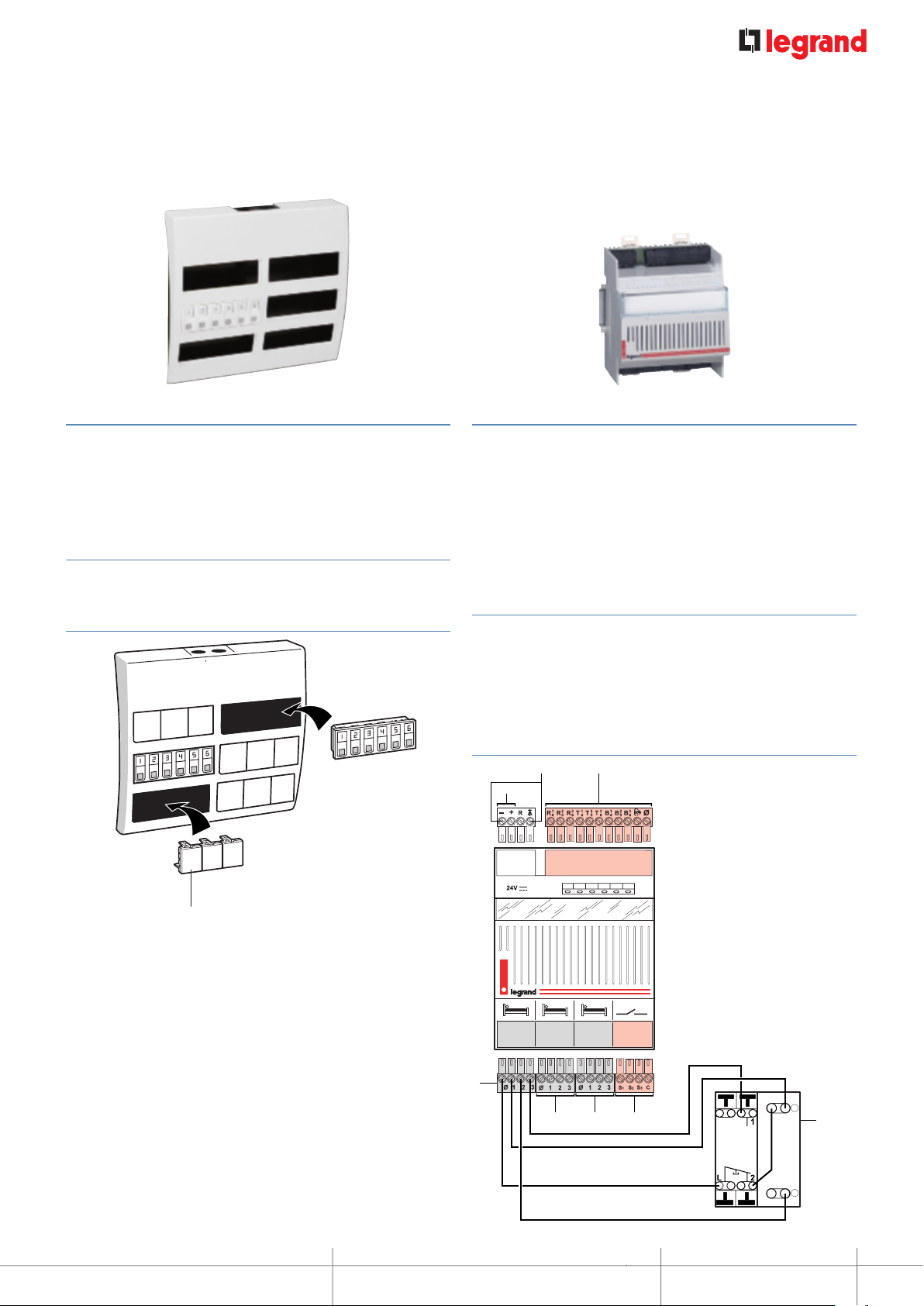
0 782 14: TABLE CONTROL UNIT
0 782 12: 3DIRECTION MANAGEMENT MODULE*
Support frame which can take up to 6 display units
Cat.No 0 766 60.
Makes it easier to run cables when installing several
displayunits.
Fit blanking plates over unused positions.
Technical characteristics
n Protection class: IP 40 with blanking plates
n Dimensions: 310 x 295 x 75 mm (36 modules)
Installation
Cat.No 770 71
Manages 3 directions.
Possibility of forwarding:
- for indicator
- for audible signal via a solid state relay
- on DECT, via a telephone coupling product
- on master indicator (lights up if the indicator on at least one of
the 3 directions is lit up).
Technical characteristics
n Power supply: 24 V=
n Consumption: min. 39 mA
max. 300 mA
n Operating temperature: 5 to 40°C
n Dimensions: 4 DIN modules
Connection
2
1
3
1- 24 V= power supply terminals
2- Master indicator or
solid state relay terminals
3- Call display unit terminals
4- Door unit direction 1
5- Door unit direction 2
6- Door unit direction 3
7- Volt-free contact for DECT,
indicator, audible signal
8- Terminal block for door unit:
0 782 04 (15W22)
4
567
* Direction: room from which the calls originate
DEVICE PRESENTATION AND INSTALLATION
R
8
W
MOSAIC NURSE CALL UNIT
7
Page 8
DEVICE PRESENTATION AND INSTALLATION
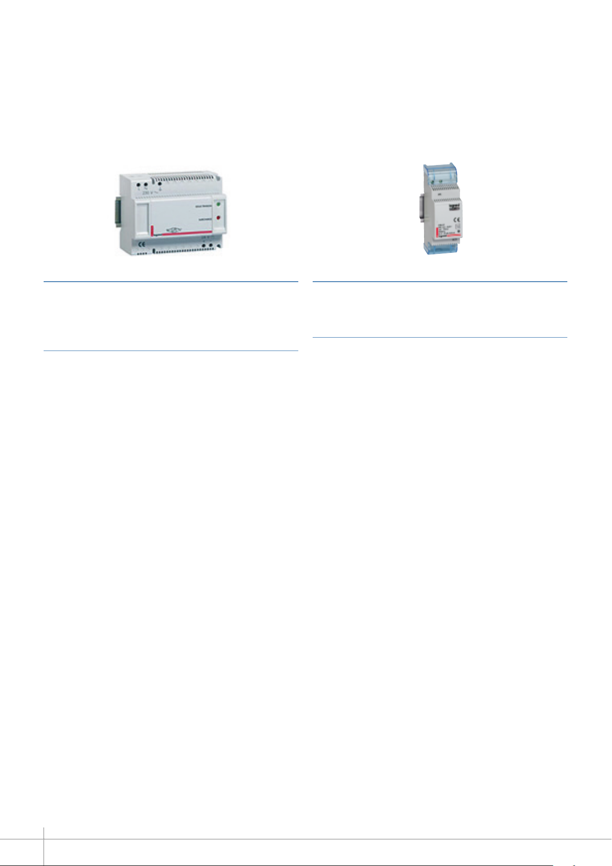
0 782 89: 24 V 2 A 48 W POWER SUPPLY
Powers the system with SELV.
Recommendation: 1 power supply for 36 directions (corresponds
to 30% of simultaneous calls max.).
Technical characteristics
n Power supply voltage: 230 VA+10% - 50/60 Hz
n Output voltage: 24 V=
n Max. rating: 2 A
n Max. power: 48 W
n Operating temperature: 5 to 40°C
n Protection class: IP 30
n Dimensions: 6 DIN modules
0 035 67: AUXILIARY POWER SUPPLY
Powers the solid state relay for information transfer (indicator or
audible signal).
Technical characteristics
n Power supply voltage: 230 VA
n BUS output voltage: 27 V=
n BUS maximum rating: 600 mA
n Max. power: 21.5 W
n Max. consumption: 26.8 W
n Operating temperature: 5 to 40°C
n Protection class: IP 20
n Dimensions: 2 DIN modules
8
Page 9

0 782 04: DOOR UNIT
1
2
Consisting of 2 white indicators to be covered with stickers (red,
green, orange or blue) and a push-button for acknowledging the
call and nurse presence.
Recommendation: Place the red sticker over the call indicator
(top indicator).
Technical characteristics
n Power supply: via management module Cat.No 0 782 12
n Operating temperature: 5 to 40°C
n Antimicrobial
n Protection class: IP 20
n Dimensions (H x W x D): 82 x 82 x 43 mm
n Installation:
- in 1-gang (2 modules) flush-mounting box Cat.No 0 800 41 or
Cat.No 0 801 41 (concrete)
- in surface mounting box Cat.No 0 802 81 (IP 20)
Connection (from 15W22)
R
Flush-mounted wall installation
Cat.No
0 800 41
Cat.No
0 801 41
Surface-mounted wall installation
l
a
i
ob
r
c
i
im
t
n
A
l
a
obi
r
c
i
im
t
n
A
W
1- Terminal block for management module: 0 782 12
2- Terminal block for door unit: 0 782 04
DEVICE PRESENTATION AND INSTALLATION
MOSAIC NURSE CALL UNIT
9
Page 10

DEVICE PRESENTATION AND INSTALLATION
0 766 85: BATHROOM CALL UNITS OR CALL BUTTON
Technical characteristics
n Power supply: via management module Cat.No 0 782 12
n Operating temperature: 5 to 40°C
n Antimicrobial
n Protection class: IP 20
n Dimensions (H x W x D): 82 x 82 x 43 mm
n Installation:
in 1-gang (2 modules) flush-mounting box Cat.No 0 800 41 or
Cat.No 0 801 41 (concrete)
- in surface mounting box Cat.No 0 802 81 (IP 20)
Flush-mounted wall installation
Cat.No
0 800 41
l
a
i
b
o
r
c
mi
i
t
n
Cat.No
A
0 801 41
Bathroom pull connection (from 15W22)
R
1
W
2
1- Terminal block for door unit: 0 782 04
2- Terminal block for bathroom call unit: 0 766 85
Call button connection (from 15W22)
Surface-mounted wall installation
10
R
1
ial
ob
r
c
mi
i
t
n
A
W
2
1- Terminal block for door unit: 0 782 04
2- Terminal block for call button: 0 766 85
Page 11

0 766 63: SOCKET FOR PUSHBUTTON CORD
1
0 783 62: PUSHBUTTON CORD
Socket for push-button cord or biomedical alarm.
Supplied on 2-module plate with blanking plate.
Technical characteristics
n Power supply: via management module Cat.No 0 782 12
n Operating temperature: 5 to 40°C
n Protection class: IP 20
n Dimensions: 82 x 82 x 36 mm
n Installation:
- in 1-gang (2 modules) flush-mounting box Cat.No 0 800 41
or Cat.No 0 801 41 (concrete)
- on the wall with surface mounting box Cat.No 0 802 81
n 12 mm fixing centres
Connection
Allows patients to call a nurse via the door unit.
For use in conjunction with socket Cat.No 0 766 63.
With 12 mm fixing centre plug for 2P socket Cat.No 0 771 50.
Technical characteristics
n Power supply: via socket for push-button cord
n Operating temperature: 5 to 40°C
n Protection class: IP 20
n Cord length: 2 m
n Ejectable from 45° angle
n NC contact
• Conductor marking
Factory wiring
connect
blue and
brown
R
2
W
1- Terminal block for socket for push-button cord Cat.No 0 766 63
2- Terminal block for door unit Cat.No 0 782 04
DEVICE PRESENTATION AND INSTALLATION
closed in rest mode
MOSAIC NURSE CALL UNIT
11
Page 12

DEVICE PRESENTATION AND INSTALLATION
17,936
+
0 771 50 + 0 782 07: BIOMEDICAL CALL PLUG AND SOCKET
Signals the end of a cycle via an alarm on the nurse call system.
For connection to portable electrical medical devices such as
syringe pumps, respirators, etc.
Comprises:
- Socket Cat.No 0 771 50
- Shunt plug Cat.No 0 782 07:
For setting biomedical alarm to standby.
Used with socket Cat.No 0 771 50.
Technical characteristics
n Power supply: via the door unit Cat.No 0 782 04
n Operating temperature: 5 to 40°C
n Protection class: IP 20
n Overall dimensions (H x W): 45 x 22.5 mm
n Installation:
- in 1-gang flush-mounting box with universal Batibox grid
Cat.No. 0 802 51
- surface-mounted with box Cat.No 0 802 81 and universal
Batibox grid Cat.No 0 802 51
- can be installed in ducting, strips or bedhead trunking units
Connection
Flush-mounted wall installation in 1-gang flush-mounting box
with grid Cat.No 0 802 51
Flush-mounted wall installation in 1-gang flush-mounting box
with grid Cat.No 0 802 51
1
R
2
1- Terminal block for socket for push-button cord Cat.No 0 766 63
2- Terminal block for door unit Cat.No 0 782 04
W
12
Page 13

0 782 43: CLAMP FOR PUSHBUTTON CORD
0 766 64: BATHROOM CALL PULLCORD
For holding the push-button cord within reach: on bedding,
clothes or the arm of a chair.
Dimensions
79,7
17,936
Bathroom call unit with vertical pull-cord button and
integrated LED indicator.
Technical characteristics
n Power supply: via the door unit Cat.No 0 782 04
n Consumption: 0.8 W
n Operating temperature: 5 to 40°C
n Protection class: IP 20
n Dimensions: 82 x 82 x 43 mm
n Installation:
- surface-mounted with box Cat.No 0 802 81
- flush-mounted in 40 mm deep 1-gang (2 modules)
flush-mounting box Cat.No 0 800 41 or 0 801 41
Connection
1
R
W
1- Terminal block for door unit Cat.No 0 782 04
2- Terminal block for bathroom call unit Cat.No 0 766 64
DEVICE PRESENTATION AND INSTALLATION
2
MOSAIC NURSE CALL UNIT
13
Page 14

DEVICE PRESENTATION AND INSTALLATION
0 766 72: DOUBLE DISPLAY CORRIDOR OVERDOOR LIGHT
Double indicator (red/white).
Displays calls and nurse presence in the corridor.
With long life LEDs.
Caution: only this catalogue number is compatible with the
Mosaic system.
Technical characteristics
n Power supply: via door unit Cat.No 0 782 04
n Consumption: 1.2 W
n Operating temperature: 5 to 40°C
n Protection class: IP 20
n Dimensions: 82 x 82 x 43 mm
n Installation:
- surface-mounted with box Cat.No 0 802 81
- flush-mounted in 40 mm deep 1-gang (2 modules)
flush-mounting box Cat.No 0 800 41 or 0 801 41
Connection
1
W
1- Terminal block for corridor overdoor light unit Cat.No 0 766 72
2- Terminal block for door unit Cat.No 0 782 04
R
R
2
W
14
Page 15

0 766 71: CALL TRANSFER LIGHT FOR CORRIDORS
0 766 42: ELECTRONIC BUZZER
Transfers calls from a department into the corridor.
Technical characteristics
n Power supply: 27 V= (via indicator power supply)
n Operating temperature: 5 to 40°C
n Protection class: IP 20
n Dimensions (H x W): 82 x 82 mm
n Installation:
- in 1-gang flush-mounting box
- surface-mounted with box Cat.No 0 802 81
Audible call transfer from a department.
Technical characteristics
n Power supply: 27 V= (via power supply Cat.No 0 035 67)
n Consumption: 9 mA
n Operating temperature: -10°C to +55°C
n Protection class: IP 41-IK 05
n Sound level: 80 dB(A) at 1 m
n Overall dimensions (H x W): 45 x 45 mm
Flush-mounted wall installation in 1-gang screw
flush-mounting box
Cat.No 0 802 51
Cat.No 0 787 22
Surface-mounted wall installation with box Cat.No 0 802 81
DEVICE PRESENTATION AND INSTALLATION
Cat.No 0 802 51
MOSAIC NURSE CALL UNIT
Cat.No 0 787 22
15
Page 16

MOSAIC NURSE CALL UNIT
CALL + NURSE PRESENT
1 - Patient calls from room
BEEEP
The patient calls from their room by
pressing the bedhead corded pushbutton.
From the nurses' station, the nurse
3
acknowledges the call by pressing
the mute button. The red indicator
changes from flashing to steady and
the audible signal stops.
2 - Nurse present in the room
1
On entering the room, the nurse
signals her presence by pressing the
door unit push-button.
21
The door unit indicator and the corridor
overdoor light flash red slowly.
The door unit indicator and the corridor
4
overdoor light change from flashing
red to steady red.
2
The red door unit indicator goes out and
the white indicator lights up. The corridor
overdoor light changes from red to white.
In the nurses' station, the room number
lights up red and flashes slowly, and the
audible signal beeps slowly.
In the nurses' station, the red indicator
goes out and the white indicator returns
to steady state.
3 - Acknowledgement of the call
1
16
On leaving the room, the nurse
presses the door unit push-button and
clears the call. All the indicators and
the overdoor light go out.
Page 17

BATHROOM CALL + NURSE PRESENT
1 - Patient calls from bathroom
BEEEP
BEEEP
1
The patient calls from the bathroom
bypulling the cord.
2
The door unit indicator, the indicator in
the bathroom and the corridor overdoor
light flash red quickly.
3
Muting is not possible from the
nurses' station. The nurse must go to
the patient's bathroom.
2 - Nurse present in the room
1
On entering the room, the nurse
signals her presence by pressing the
door unit push-button.
2
The door unit red indicator and the
corridor overdoor light go out. The door
unit indicator and the corridor overdoor
light come on with a steady white light.
Since bathroom calls are priority calls, the nurse must go to the room. Muting is not possible.
In the nurses' station, the room number
is displayed, the indicator flashes red
quickly and the audible signal beeps
quickly.
In the nurses' station, the red indicator
goes out and the white indicator returns
to steady state.
3 - Acknowledgement of the call
1
On leaving the room, the nurse
presses the door unit push-button and
clears the call. All the indicators and
the overdoor light go out.
DEVICE PRESENTATION AND INSTALLATION
MOSAIC NURSE CALL UNIT
17
Page 18

MOSAIC NURSE CALL UNIT
EMERGENCY CALL
1 - Patient calls from room
AND/OR
2 - Nurse present in the room
3 - Emergency call
1
In the room, the nurse activates
the emergency call by pressing the
bedhead corded push-button.
4 5 6
Muting is not possible
from the nurses' station.
The nurse must go to the
patient's bedroom.
7
On leaving the room, the
nurse presses the door unit
push-button and clears the
call. All the indicators and
the overdoor light go out.
2 3
The door unit indicators and the
corridor over
alternating red and white.
On entering the room, the
2nd nurse presses the door
unit push-button.
door light flash quickly,
BEEEP
BEEEP
In the nurses' station, the indicator
flashes quickly, alternating red and white;
the audible signal beeps quickly.
The door unit red indicator
and the corridor overdoor
light go out. The door unit
indicator and the corridor
overdoor light come on with a
steady white light.
In the nurses' station, the
red indicator goes out and
the white indicator returns to
steady state.
18
Page 19

NURSE PRESENT + CALL FROM ANOTHER ROOM
1 - Patient calls from room 1
2 - Nurse present in room 1
3 - Another patient calls from room 2
BEEEP
BEEEP
1 2
The patient calls from
room 2 by pressing the
bedhead corded pushbutton.
On entering room 2, the
3 4
2nd nurse presses the
doorunit push-button.
The door unit indicator and
the corridor overdoor light for
room 2 flash red slowly
In room 1 (and in the other
rooms in the department
where a nurse is present):
the door unit indicators and
corridor overdoor lights stop
flashing.
In the nurses' station, the
room number lights up red
and flashes slowly, and the
audible signal beeps slowly.
In the nurses' station, room
number 2 stops flashing and
returns to a steady white light.
In room 1 (and in the other
rooms in the department
where a nurse is present):
the door unit indicators and
corridor overdoor lights flash
white slowly.
DEVICE PRESENTATION AND INSTALLATION
MOSAIC NURSE CALL UNIT
19
Page 20

MOSAIC NURSE CALL UNIT
NURSE PRESENT + CALL FROM ANOTHER BATHROOM
1 - Patient calls from room 1
2 - Nurse present in room 1
3 - Another patient calls from bathroom 2
1
The patient calls
from bathroom 2 by
pulling the cord.
On entering room2,
the 2nd nurse
3 4
presses the door
unit push-button.
2
The door unit indicator, the indicator in
the bathroom and the corridor overdoor
light flash red quickly.
In room 1 (and in the other rooms in the
department where a nurse is present):
the door unit indicators and corridor
overdoor lights stop flashing.
BEEEP
BEEEP
In the nurses' station, the
room number is displayed,
the indicator flashes red
quickly and the audible
signal beeps quickly.
In the nurses' station, room
number 2 stops flashing and
returns to a steady white
light.
In room 1 (and in the other
rooms in the department
where a nurse is present):
the door unit indicators
and corridor overdoor
lights flash white quickly.
20
Page 21

CALL PRIORITIES
PRIORITY
+
CALL
TYPE
Emergency
call (help)
from
bathroom
Emergency
call (help)
from
bedroom
Biomedical
alarm
Call from
bathroom
CONTROL
DISPLAY ON DOOR UNIT AND
CORRIDOR OVERDOOR LIGHT
DISPLAY ON
CONTROL UNIT
BEEEP
BEEEP
BEEEP
BEEEP
BEEEP
BEEEP
BEEEP
BEEEP
MUTING
FROM THENURSE'S
CONTROL UNITS
NO
NO
NO
NO
-
Call from
bedroom
DEVICE PRESENTATION AND INSTALLATION
BEEEP
MOSAIC NURSE CALL UNIT
YES
21
Page 22

MOSAIC NURSE CALL UNIT
WIRING: CALL + NURSE PRESENCE INSTALLATION + FOR NURSING HOMES
AND RESIDENTIAL HOMES FOR THE ELDERLY
Single room
+ shower room with WC
1
2
R
W
3
2 1
4
W
R R
R
B
Rm 2
4-wire
4
W
R
3
R
W
3
WC 3
5
076660
Secondary
control unit
8
4-wire
B
Socket for push-button cord Cat. No. 0 766 63 + push-button cord
1
Separate WC no. 3
Cat. No. 0 783 62
2
Bathroom call pull cord Cat. No. 0 766 64
Use wires with identical diameter. Recommendation: Use 0.6 mm2SYT cable.
If there is no bathroom
pull-cord, make a shunt:
R
078204
W
If there is no push-button cord
(same as WC no. 3), make a shunt:
078204
22
Door unit Cat. No. 0 782 04
3
Double display corridor overdoor light unit Cat. No. 0 766 72
4
R
W
Page 23

Twin room
+ shower room with WC
1 1
2
Connection terminal
Main
control unit
R
W
3
1
W
R
4
Rm 1
4-wire
2-wire
3-wire/3-direction
LN
076660
5
N
IO
S
N
E
T
S
U
O
S
E
G
AR
H
C
R
U
S
6
7
Rm 1
Rm 2
WC 3
6-direction call display unit Cat. No. 0 766 60
5
24 V power supply Cat. No. 0 782 89
6
3-direction management module Cat. No. 0 782 12
7
Bathroom call unit Cat. No. 0 766 85
8
DEVICE PRESENTATION AND INSTALLATION
MOSAIC NURSE CALL UNIT
23
Page 24

MOSAIC NURSE CALL UNIT
WIRING: CALL + PRESENCE INSTALLATION WITH CALL VIA CALL BUTTON AND INFORMATION TRANSFER
Single room
+ shower room with WC
W
10
OR
1
2
R
R
W
LN
W
R
6
Rm 2
4-wire
2
1
5
W
R
2
R
W
3
Separate
WC no. 3
6
7
076660
Secondary
control unit
4-wire
Electronic buzzer Cat. No. 0 766 42 or Call-only corridor
1
light unit Cat. No. 0 766 71
2
Auxiliary power supply Cat. No. 0 035 67
24 V= solid state relay (1 module)
3
24
Use wires with identical diameter. Recommendation: Use 0.6 mm2SYT cable.
10
W
Socket for push-button cord Cat. No. 0 766 63 + push-button cord
4
Cat. No. 0 783 62
5
Bathroom call unit Cat. No. 0 766 64
Door unit Cat. No. 0 782 04
6
Page 25

Twin room
+ shower room with WC
W
W
W
10 10 10
Connection
terminal
R
W
1
W
R
Rm 1
5
6
5
4-wire
2-wire
LN
076660
3-wire/3-direction
Main
control unit
6-direction call display unit Cat. No. 0 766 60
7
24 V power supply Cat. No. 0 782 89
8
7
N
IO
S
N
E
T
S
U
O
S
E
G
R
A
H
C
R
U
S
8
9
3-direction management module Cat. No. 0 782 12
10
Bathroom call unit Cat. No. 0 766 85
9
DEVICE PRESENTATION AND INSTALLATION
Rm 1
Rm 2
WC 3
MOSAIC NURSE CALL UNIT
25
Page 26

MOSAIC NURSE CALL UNIT
WIRING: CALL + BIOMEDICAL + PRESENCE INSTALLATION WITH DECT INTERFACE (INTEGRATED TRACEABILITY)
Single room
+ shower room with WC
1
10
2
Connection terminal
R
3
2 1
4
W
R R
W
Rm 2
4-wire
4
W
R
3
4-wire
R
W
3
WC 3
8
W
Socket for push-button cord Cat. No. 0 766 63 + push-button cord
1
Separate WC no. 3
Cat. No. 0 783 62
2
Bathroom call unit Cat. No. 0 766 64
Door unit Cat. No. 0 782 04
3
26
Use wires with identical diameter. Recommendation: Use 0.6 mm2SYT cable.
5
076660
Secondary
control unit
Double display corridor overdoor light unit Cat. No. 0 766 72
4
6-direction call display unit Cat. No. 0 766 60
5
24 V power supply Cat. No. 0 782 89
6
Page 27

Common
WC 3
Rm 1
Rm 2
Twin room
+ shower room
with WC
1 1
2
Connection terminal
4-wire
Main
control unit
R
1
W
3
3-wire/3-direction
LN
W
R
4
Rm 1
7
N
IO
S
N
E
T
S
U
O
S
E
G
AR
H
C
R
U
S
2-wire
6
Rm 1
WC 3
Rm 2
ELV equipment room
076660
5
RS232
PABX
9
Board with 16 or
32 volt-free contacts
3-direction management module Cat. No. 0 782 12
7
Bathroom call unit Cat. No. 0 766 85
8
9
Telephone coupling product (telephone system)
10
Biomedical alarm Cat. Nos. 0 771 50 + 0 782 07
DEVICE PRESENTATION AND INSTALLATION
DECT
TERMINAL
MOSAIC NURSE CALL UNIT
27
Page 28

COMMISSIONING
+
24V
0 782 12
This MUST be done with the POWER OFF before commissioning and each time the installation is modified
(addition/deletion of a product). The management module risks being damaged if wired incorrectly.
CHECK BEFORE SWITCHON
Repeat the steps for each direction.
Step 1: Unplug the connector
Ø
3
2
1
Ø
3
2
1
Ø
Step 2: Test circuit 1
Ω
Ω
OFF
Ω
2k
V/Ω
CM
2
1
S3 C
2
S
S1
3
25 < Ω < 2500
Step 3: Test circuit 2
3
2
1
Ø
Step 4: Test circuit 3
3
2
1
Ø
Ω
Ω
OFF
Ω
2k
V/Ω
CM
25 < Ω < 2500
Ω =
∞
ON
Ω
Ω
OFF
Ω
2k
V/Ω
CM
0< Ω <500
Ω =
∞
28
Ω =
3
2
1
Ø
∞
ON
OR
ON
3
2
1
Ø
Ω
Ω
OFF
Ω
2k
V/Ω
CM
0< Ω <500
Ω =
∞
Page 29

RESETTING THE MODULE
+
R
–
1
2
3
1
2
3
1
2
3
T
B
B
B
6
Ø
4
5
6
24V
R
R
R
T
T
4
5
6
4
5
12
11
1
60
5
55
10
50
45
9
40
8
7
2
10
3
15
20
4
35
25
30
5
6
5s
0 782 12 0 782 12
1
2
3
1
2
3
1
2
+
R
–
R
R
R
T
T
4
5
6
4
3
T
B
B
B
5
6
Ø
4
5
6
24V
COMMISSIONING
MOSAIC NURSE CALL UNIT
29
Page 30

TROUBLESHOOTING
FAULT TYPE DIAGNOSTICS
The corridor overdoor light is flashing white quickly Door unit Cat.No 0 782 04 faulty
The corridor overdoor light is flashing red slowly Push-button cord faulty
The corridor overdoor light is flashing red quickly Biomedical system or bathroom pull-cord faulty
One of the room LED indicators is faintly
lit and never goes out
Management module is damaged and needs to be replaced
30
Page 31

TROUBLESHOOTING
MOSAIC NURSE CALL UNIT
Page 32

FOLLOW
US ON
www.legrand.com
www.youtube.com/legrand
www.twitter.com/legrand
Head office
and International Management
87045 Limoges Cedex - France
Tel: +33(0)5 55 06 87 87
Fax: +33(0)5 55 06 74 55
LE08358AB_EN - April 2016
 Loading...