

Page 1

SPECIFICATIONS
Power Supply........................Lithium 3V coin cell CR2450
Operating Temperature ............ 32° to 104°F (0° to 40° C)
Output ........................................... TopDog RF commands
DESCRIPTION
The Miro Key Fob (MKFOB) is a battery powered, Top Dog™
enabled remote device, which allows the user to recall and
record scenes in a Miro wireless network. The key fob can
be placed on a key-chain or in the included visor clip and
attached to a car visor or similar surface.
The unit has three operating modes. The operating mode
determines which scenes the MKFOB will execute. It is
equipped with three buttons so it can execute up to three
scenes that are recorded using the key fob itself or a Miro
wireless room or house scene controller.
The open field operating range between the key fob and
other Miro wireless devices is 100 feet. The actual range
will vary according to the type of construction being used
and whether there are objects between the user and the
devices on which the scenes will execute. Since the key fob
uses radio transmission (as opposed to infrared), line-ofsight is not required.
A typical key fob application is to control house level scenes
using operating Mode-1. For example:
• Button 1 turns on a pathway of light in the house
• Button 2 turns off all except for selected night-lights
• Button 3 turns off all lights
Another common application is to control house level
scenes including a “panic” scene using Mode-2. For
example:
• Button 1 turns on a pathway of lights in the house
• Button 2 turns off all lights in the house
• Button 3 evokes the panic feature (lights on dimmers
flash and those on switches come on to full bright)
A less common, but possible application is to control room
level and house level scenes using Mode-3. For example:
• Button 1 recalls the lights in a particular room, such as
the great room
• Button 2 turns off all, or selected lights in the room
• Button 3 turns off all, or selected house lights
These three applications are typical, however the user can
record scenes in any number of ways. For example, Mode-1
could be used to have three different arrival scenes (lights
on) or leaving/night scenes (lights off). Just remember that
each button can only recall one specific scene as described
in the Operating Mode sections on the next page. For
example, house scenes 1, 5, and 11 are the only scenes that
can be recalled in Mode-1.
MKFOB v2
Key Fob Remote Control
Installation Instructions
MKFOB Visor Clip
Top Dog™ Wireless Communication
Wireless devices use radio signals to communicate with
each other to control lighting and other types of electric
loads in selected areas. These wireless devices use the
900MHz band for high-speed control communication. Using
Watt Stopper “frequency-agile” Top Dog™ technology,
these wireless devices avoid interference with other
900MHz devices, such as cordless phones and baby
monitors.
APPLICATION ASSISTANCE
The MKFOB functions as part of a network that contains
Top Dog enabled wireless devices that may include Miro
architectural or decorator-style in-wall devices as well as
portable remote controls and other accessories. Prior to
using the key fob the other devices should be installed and
programmed.
A MKFOB may be added to a Miro or Miro decorator
wireless installation at any time and there is not any limit
to the number that can be used.
Normally, at least one room or house scene controller
is installed in a Miro system. To operate the key fob in a
Miro system without a scene controller, contact technical
support or look for the Application Note on our website.
Instructions for other Miro devices, including
binding operations and use are included with
the devices. Application support information and
installation guides are available on our website.
* Throughout this instruction, we use “yellow” to
represent the yellow/amber color of the LED, which is a
combination of green and red.
Page 2
KEY FOB SETUP INSTRUCTIONS:
Prior to setting up the key fob:
• Install your Top Dog enabled wireless devices (dimmers,
switches, plug-in modules, scene controllers, etc.).
• Configure your Top Dog enabled wireless system (including
scene setting if you have scene controllers in the system)
following the directions provided with each device.
• We recommended that you also read the Miro Installation
Manual, which is available online.
Now you can set up the key fob to work within the wireless
system by simply setting the House ID and Setting the Operating
Mode. If your system does NOT include a scene controller, see
the Application Note titled “Easy Setup Without a House Scene
Controller,” which is available online.
Set House ID
All Top Dog enabled wireless devices installed in the same home
must acquire the same unique House ID before use. This process
is called house binding. Each device is bound to all other Top Dog
enabled wireless devices in the house. The following sequence
assumes that the other devices in the house have already
received the House ID.
1. Momentarily press any button on the MKFOB. The LED
should be solid yellow/amber (a combination of green
and red) and should remain lit for about one minute. This
indicates that it has not yet acquired a House ID; proceed
to step 2. If the LED is a color other than yellow* see
Troubleshooting.
2. Go to any device already bound to the house (identified
by a solid green LED) and initiate binding by pressing the
binding activation keys until its LED flashes yellow (about
2 seconds). Binding is typically initiated by simultaneously
pressing and holding the top and bottom of a paddleoperated device.
3. If the LED on the MKFOB is still lit when you complete the
previous step, it turns green when it receives the House ID,
then it begins flashing green.
If the LED on the MKFOB is not lit, press and hold any button
until the LED turns green indicating that it received the
House ID.
4. Return to the same device used to initiate the binding and
end the binding by pressing the binding activation keys until
the device LED changes to solid green (about 2 seconds). All
device LEDs should now be solid green.
Set the MKFOB Operating Mode
Review the following sections that describe Operating Mode-1,
Operating Mode-2 and Operating Mode-3. Choose the operating
mode that you wish to use. Note that each operating mode
recalls specific scenes. For example, Operating Mode-1 (default)
recalls house scenes 1, 5, and 11 from buttons 1, 2, and 3.
LED
Buttons
1
2
3
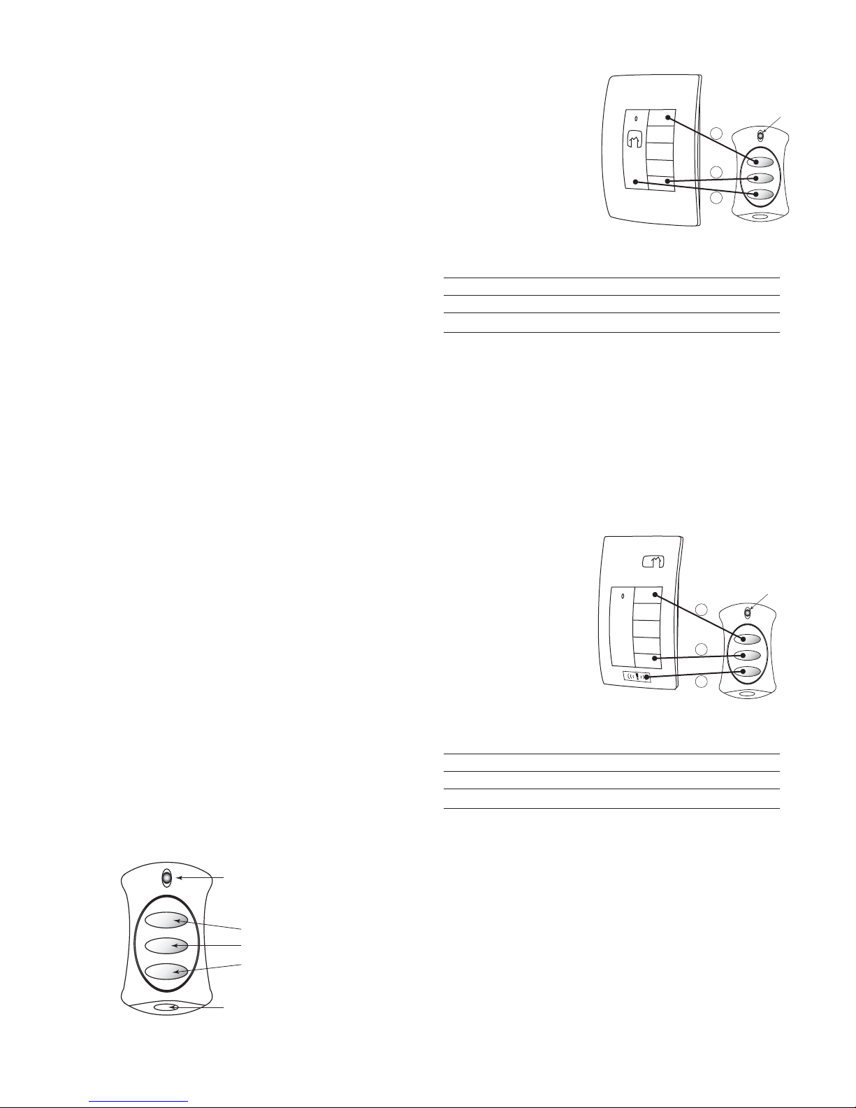
Operating Mode-1 (Default)
In Mode-1, the MKFOB is
bound to the house. Mode-1
is used to recall and record
House scenes 1, 5, and 11.
Scene 11 is the scene that
executes when you press
the bottom of the ON/OFF
paddle on a house level
controller, which has a
default operation of turning
off all devices bound to the
house.
MODE-1
Button Recall
1 House Scene 1
2 House Scene 5
3 House Scene 11 (bottom of house controller paddle)
Use the procedure below to set the MKFOB to Mode-1.
1. Start binding from the MKFOB: Simultaneously press
and hold button 1 and 2 until the LED starts flashing
yellow (approximately 2 seconds).
2. Press and hold MKFOB button 1 until the LED
changes to green then starts flashing yellow again
(approximately 2 seconds).
3. End the binding from the MKFOB: Simultaneously press
and hold button 1 and 2 until the LED stops flashing
yellow and turns green (approximately 2 seconds).
MKFOB
Mode-1
Scene
1
5
11
Operating Mode-2
In Mode-2 the MKFOB
is bound to the house.
Buttons 1 and 2 are the
same as Mode-1 but button
3 is used to toggle PANIC
mode (scene 14). In other
words, a press of button
3 toggles the command
that is issued by the device
from Over-Ride to Scene
14 (Panic) to Revert OverRide in order to restore the
home to the previous state.
MODE-2
Button Recall
1 House Scene 1
2 House Scene 5
3 Panic/Cancel Panic (Toggle house scene 14)
Use the procedure below to set the MKFOB to Mode-2.
1. Start binding from the MKFOB: Simultaneously press
and hold button 1 and 2 until the LED starts flashing
yellow (approximately 2 seconds).
2. Press and hold MKFOB button 2 until the LED
changes to green then starts flashing yellow again
(approximately 2 seconds).
3. End the binding from the MKFOB: Simultaneously press
and hold button 1 and 2 until the LED stops flashing
yellow and turns green (approximately 2 seconds).
MKFOB
Mode-2
Scene
1
5
14
LED
LED
Key-chain loop
Page 3

Operating Mode-3
In Mode-3, the MKFOB is bound to an individual room to allow the
device to record and recall both Room and House scenes. This is
done so that multiple key fobs can be used in the wireless system
to control different areas within the home to perform localized
tasks.
MKFOB
Mode-3
Room
Scene
1
5
MODE-3
Button Recall
1 Room Scene 1
2 Room Scene 5
3 House Scene 5
First, set the MKFOB to Mode-3.
1. Start binding from the MKFOB: Simultaneously press and
hold button 1 and 2 until the LED starts flashing yellow
(approximately 2 seconds).
2. Press and hold MKFOB button 3 until the LED changes to
green then starts flashing yellow again (approximately 2
seconds).
3. End the binding from the MKFOB: Simultaneously press and
hold button 1 and 2 until the LED stops flashing yellow and
turns green (approximately 2 seconds).
Next, bind the MKFOB to the desired Room.
1. Go to the room controller device and initiate binding by
pressing the binding activation keys until its LED flashes
yellow (about 2 seconds). Binding is typically initiated by
simultaneously pressing and holding the top and bottom of a
paddle-operated device.
2. Press and release any button on the MKFOB to wake it up
and lock onto the binding operation.
If its LED flashes yellow, it is already bound to the room. You
can skip to step 3.
If it flashes green, it is not yet bound to the room.
Simultaneously press MKFOB buttons 1 and 2
turns yellow (about 2 seconds) indicating that the MKFOB is
bound to the room.
3. Return to the same device used to initiate the binding and
end the binding by pressing the binding activation keys until
the device LED changes to solid green (about 2 seconds).
When the MKFOB receives a close binding message (or no
binding message is heard for 4.5 seconds) the MKFOB goes
to sleep mode and the LED turns off.
House
Scene
5
until the LED
OPERATION
When a MKFOB is added to a system its scene buttons execute
the same scenes as other house or room level scene controllers
to which it is bound. (Refer to the Operating Mode charts for
specific scenes recalled depending upon mode selected). To
revise a scene, record the scene from the room or house level
device to which the MKFOB is bound.
Lock Key Fob
Locking the MKFOB prevents it from being inadvertently reset to
factory defaults. Lock the key fob after scene configuration.
To Lock: Start a binding from the MKFOB (simultaneously press
and hold button 1 and 2 until the LED starts flashing yellow).
Press and hold buttons 1 and 3 until the LED blinks red.
Press and hold button 1 and 2 to terminate the process.
To Unlock: Start a binding from the MKFOB (simultaneously press
and hold button 1 and 2 until the LED starts flashing yellow).
Press and hold buttons 2 and 3 until the LED blinks green.
Press and hold button 1 and 2 to terminate the process.
To prevent inadvertent scene reprogramming due to
accidental pressing of a MKFOB button, lock the house
confi guration from a house level scene controller.
Battery Usage
To ensure that the battery is not unnecessarily discharged, the
MKFOB goes to sleep when it is not
sending messages. When it wakes to send
a message, it immediately goes back
into the sleep mode once the message
transmission has been confirmed and no
other button activity is present.
Installing a New Battery
To install the battery, you must open
the MKFOB housing. While the unit is
designed to withstand handling, there is
a circuit board inside, so you should avoid
opening the housing in areas prone to excessive static electricity.
Touch a grounded surface to discharge excessive static electricity
from your body before touching the printed circuit board.
1. Open the MKFOB
housing by inserting
the edge of a coin into
the notch on the corner
Back Housing
inside chamber
LED
of the unit, near the
key-chain loop. Twist
the coin to pop open the
housing.
2. Remove the back
housing; on it is the
product identification
label with battery
instructions. The circuit
board and battery
Printed Circuit
Board (front)
remains in the front
housing.
3. Remove the old battery by pushing it out of
the metal clip that holds it in place.
4. Install the new CR2450 3Volt battery with the
positive (+) plane against the metal clip.
5. Reassemble the unit then snap the housing
together. Test the buttons. Make sure you
get the appropriate soft click when you press
each button.
LED
Key-chain
Loop
3V
Page 4

TESTING
After completing the MKFOB setup, you can test scene recall
by pressing a button. You should hear a soft click when
you press each button. Scene recall works best with an
immediate release of the button. The LED should come on
and be green then turn off a second or two after you release
the button.
TROUBLESHOOTING
During Set House ID, the LED is not flashing on some
Wireless devices.
• If an LED is solid green before initiating house ID binding:
The device already has another house ID. Reset
it to the factory default so that it can be bound to
the desired house ID. Resetting to factory defaults
is described in the “I need to start over” issue.
• If LED is solid yellow after initiating house ID binding:
The device may be out of range of the initiating device.
Move the MKFOB closer to the initiating device. It may
be necessary to add a MRR2 Repeater if reception
to a particular area of the house is blocked.
The LED does not light when I press a button.
The battery may be out of position or
may need replacement. See Battery
Usage/Installing a New Battery.
The MKFOB won’t accept the House ID binding and it will
not initiate a binding.
See “There is no click ...” below.
There is no click when I press a button.
The key membrane inside the MKFOB housing may be
out of position. Contact technical support for assistance.
A device that is included in a scene does not respond
appropriately when I invoke the scene from the MKFOB.
The non-responsive device may be out of range of
the MKFOB. Move the MKFOB closer to the device
and invoke the scene from the MKFOB. If the
device responds appropriately from this distance,
it may be necessary to install an MRR2 Repeater
at a location that is within range of the location
from which the MKFOB is typically operated.
I need to start over.
You can reset any wireless device to factory default settings
by pressing and holding its binding activation buttons until
its LED changes to solid yellow (approximately 10 seconds).
For the MKFOB, the binding activation buttons are 1
and 2. During the process, the LED fl ashes yellow and
when the reset is complete, it changes to solid yellow.
The yellow LED stays lit for approximately one minute
as it waits to hear a binding message. The device can
then be reconfi gured, exactly like any new device.
To set the House ID in the MKFOB, initiate a binding
from any previously bound device in the house.
FCC Notice
This equipment has been tested and found to comply with
the limits for a Class B digital device, pursuant to part 15
of the FCC Rules. These limits are designed to provide
reasonable protection against harmful interference in a
residential installation. This equipment generates, uses and
can radiate radio frequency energy and, if not installed and
used in accordance with the instructions, may cause harmful
interference to radio communications. However, there is no
guarantee that interference will not occur in a particular
installation. If this equipment does cause harmful interference
to radio or television reception, which can be determined by
turning the equipment off and on, the user is encouraged to
try to correct the interference by one or more of the following
measures:
• Reorient or relocate the receiving antenna.
• Increase the separation between the equipment and
receiver.
• Connect the equipment into an outlet on a circuit different
from that to which the receiver is connected.
• Consult the dealer or an experienced radio/TV technician
for help.
Caution: Any changes or modifications to this device not
explicitly approved by the manufacturer could void your
authority to operate this equipment.
WARRANTY INFORMATION
Manufacturer warranties its products to be free of
defects in materials and workmanship for a period
of five (5) years. There are no obligations or liabilities
on the part of manufacturer for consequential
damages arising out of, or in connection with, the
use or performance of this product or other indirect
damages with respect to loss of property, revenue or
profit, or cost of removal, installation or reinstallation.
Watt Stopper Customers contact: Vantage Customers contact:
2800 De La Cruz Blvd.
Santa Clara, CA 95050
Phone: 800.879.8585
www.wattstopper.com
1061 South 800 East
Orem, UT 84057
Phone: 800.555.9891
www.vantagecontrols.com
Please
Recycle
07071r2 1/2008
 Loading...